EP1784242B1 - Golf club head having a bridge member and a damping element, and method of reducing vibrations of a golf club head upon impact with a golf ball - Google Patents
Golf club head having a bridge member and a damping element, and method of reducing vibrations of a golf club head upon impact with a golf ball Download PDFInfo
- Publication number
- EP1784242B1 EP1784242B1 EP05782555.6A EP05782555A EP1784242B1 EP 1784242 B1 EP1784242 B1 EP 1784242B1 EP 05782555 A EP05782555 A EP 05782555A EP 1784242 B1 EP1784242 B1 EP 1784242B1
- Authority
- EP
- European Patent Office
- Prior art keywords
- club head
- golf club
- bridge member
- golf
- iron
- Prior art date
- Legal status (The legal status is an assumption and is not a legal conclusion. Google has not performed a legal analysis and makes no representation as to the accuracy of the status listed.)
- Not-in-force
Links
Images


Classifications
-
- A—HUMAN NECESSITIES
- A63—SPORTS; GAMES; AMUSEMENTS
- A63B—APPARATUS FOR PHYSICAL TRAINING, GYMNASTICS, SWIMMING, CLIMBING, OR FENCING; BALL GAMES; TRAINING EQUIPMENT
- A63B53/00—Golf clubs
- A63B53/04—Heads
-
- A—HUMAN NECESSITIES
- A63—SPORTS; GAMES; AMUSEMENTS
- A63B—APPARATUS FOR PHYSICAL TRAINING, GYMNASTICS, SWIMMING, CLIMBING, OR FENCING; BALL GAMES; TRAINING EQUIPMENT
- A63B53/00—Golf clubs
- A63B53/04—Heads
- A63B53/0433—Heads with special sole configurations
-
- A—HUMAN NECESSITIES
- A63—SPORTS; GAMES; AMUSEMENTS
- A63B—APPARATUS FOR PHYSICAL TRAINING, GYMNASTICS, SWIMMING, CLIMBING, OR FENCING; BALL GAMES; TRAINING EQUIPMENT
- A63B53/00—Golf clubs
- A63B53/04—Heads
- A63B53/047—Heads iron-type
-
- A—HUMAN NECESSITIES
- A63—SPORTS; GAMES; AMUSEMENTS
- A63B—APPARATUS FOR PHYSICAL TRAINING, GYMNASTICS, SWIMMING, CLIMBING, OR FENCING; BALL GAMES; TRAINING EQUIPMENT
- A63B60/00—Details or accessories of golf clubs, bats, rackets or the like
-
- A—HUMAN NECESSITIES
- A63—SPORTS; GAMES; AMUSEMENTS
- A63B—APPARATUS FOR PHYSICAL TRAINING, GYMNASTICS, SWIMMING, CLIMBING, OR FENCING; BALL GAMES; TRAINING EQUIPMENT
- A63B60/00—Details or accessories of golf clubs, bats, rackets or the like
- A63B60/02—Ballast means for adjusting the centre of mass
-
- A—HUMAN NECESSITIES
- A63—SPORTS; GAMES; AMUSEMENTS
- A63B—APPARATUS FOR PHYSICAL TRAINING, GYMNASTICS, SWIMMING, CLIMBING, OR FENCING; BALL GAMES; TRAINING EQUIPMENT
- A63B60/00—Details or accessories of golf clubs, bats, rackets or the like
- A63B60/54—Details or accessories of golf clubs, bats, rackets or the like with means for damping vibrations
-
- A—HUMAN NECESSITIES
- A63—SPORTS; GAMES; AMUSEMENTS
- A63B—APPARATUS FOR PHYSICAL TRAINING, GYMNASTICS, SWIMMING, CLIMBING, OR FENCING; BALL GAMES; TRAINING EQUIPMENT
- A63B53/00—Golf clubs
- A63B53/04—Heads
- A63B2053/0491—Heads with added weights, e.g. changeable, replaceable
-
- A—HUMAN NECESSITIES
- A63—SPORTS; GAMES; AMUSEMENTS
- A63B—APPARATUS FOR PHYSICAL TRAINING, GYMNASTICS, SWIMMING, CLIMBING, OR FENCING; BALL GAMES; TRAINING EQUIPMENT
- A63B2209/00—Characteristics of used materials
Definitions
- the present invention relates to golf clubs. More particularly, the invention concerns a cavity back golf club head having a bridge member extending across a rear cavity.
- the invention provides a damping element in the rear cavity of a cavity back golf club head to improve the accuracy, feel, and sound of a golf shot upon impact with a golf ball.
- Various golf club heads have been designed to improve a golfer's accuracy by assisting a golfer to square the club head face at impact with a golf ball.
- a number of these golf club heads reposition the weight of the golf club head in order to alter the location of the center of gravity.
- the location of the center of gravity of the golf club head is one factor that determines whether a golf ball is propelled in the intended direction.
- the center of gravity When the center of gravity is positioned behind the point of engagement on the contact surface, the golf ball follows a generally straight route.
- the center of gravity is spaced to a side of the point of engagement, however, the golf ball may follow a route that curves left or right, which is often referred to as a hook or a slice.
- the route of the golf ball may exhibit a boring or climbing trajectory.
- a golf club head may have a tendency to vibrate creating a hard hitting feel and sound when the club head contacts the golf ball.
- the hard hitting feel and sound at impact may be perceived by the golfer as the product of a good distance shot.
- excessive vibration may affect the accuracy of the golf shot and may place unnecessary stresses on the hands or joints of the golf player. More experienced players prefer a softer hitting feel and sound when the club head contacts the golf ball. Therefore, there is a need in the art for a golf club head that provides a softer feel and sound upon impact with a golf ball indicative of a more accurate and controlled golf shot.
- the golf club head should reduce excessive vibrations in order to prevent unnecessary stresses on a golfer's hands or joints while still providing for good distance and accuracy.
- WO 2004/012492 discloses a golf club head having a bridge member.
- a wall may extend from the sole portion or the top portion of the golf club head and be secured to the bridge member.
- the wall may provide a vibration damping effect upon impact of the striking face with a golf ball.
- US 2003/0228928 discloses a golf club head comprising: a club head main body to which a face plate is attached, the club head main body comprising a sole portion and a backside wall portion, the backside wall portion extending upward from the sole portion, leaving a space from said back face; and an insert made of an elastic material and interposed between the back face of the face plate and the backside wall portion.
- JP 09239077 discloses a golf club head having a bridge member, wherein a vibration absorber is clamped between the bridge member and the rear face of the golf club head.
- a wall extending from the sole portion, or the top portion of the golf club head to the bridge member.
- the present invention also relates to a method of reducing vibrations of a golf club head as specified in independent claim 22. Preferred embodiments are specified in the dependent claims.
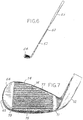
- FIGS. 1-5 are representative of the long iron clubs
- FIGS. 6-10 are representative of the short iron clubs.
- golf club 10 includes a shaft 12 and a golf club head 14.
- the golf club head 14 of FIG. 1 may be representative of a two iron golf club head of the present invention.
- the shaft 12 of golf club 10 may be made of various materials such as steel, titanium, graphite, or a composite material.
- a grip 16 is positioned on the shaft 12 to provide a golfer with a slip resistant surface in which to grasp golf club 10.
- the golf club head 14 comprises a body 15 that includes a heel 21 and toe 23.
- the heel 21 is attached to a hosel 22 for connecting the shaft 12 of FIG. 1 to the golf club head 14.
- the body 15 also includes a top portion 24 and a sole portion 25.
- a striking face 26 is connected between the top portion 24 and the sole portion 25, and between the toe 23 and the heel 21.
- the striking face 26 provides a contact area for engaging and propelling a golf ball in an intended direction.
- the striking face 26 comprises horizontal grooves 27 for the removal of water and grass from the striking face 26.
- the body 15 of golf club head 14 may be constructed of various materials such as steel, titanium, aluminum, tungsten, graphite, polymers, or composites.
- FIG. 3 illustrates a rear view of a golf club head 14.
- Golf club head 14 includes a rear face 30 positioned opposite the striking face 26.
- the rear face 30 forms a first rear cavity 32 having a large opening extending towards the rear face 30.
- a bridge member 34 extends across the first rear cavity 32, connecting the heel 21 to the toe 23.
- bridge member 34 may also be extended across the first rear cavity 32 and connected to various other locations on the golf club head 14 as shown, for example, in U.S. Pat. No. 6,450,897 issued on Sep. 17, 2002 .
- Bridge member 34 may be made of various shapes such as rectangle, oval, triangle, trapezoid, square or other symmetrical or asymmetrical shapes.
- Bridge member 34 may also have a non-uniform width or thickness throughout its length.
- Bridge member 34 may be connected to the toe 23 and heel 21 using screws 35. Those skilled in the art will realize that bridge member 34 may be connected to the toe 23 and the heel 21 using fewer or additional connection points and through numerous other connection means which fall within the scope of the present invention.
- bridge member 34 may also be formed with the golf club head 14 in a single casting making the bridge member 34 integral with the golf club head 14.
- a second rear cavity 38 is shown in FIG. 3 below the bridge member 34.
- FIG. 4 a cross-sectional view of golf club head 14, not in accordance with the invention, is illustrated.
- a wall 40 extends from the sole portion 25 to the bridge member 34.
- the wall 40 creates the second rear cavity 38 having an opening positioned below bridge member 34.
- the wall 40 may comprise a front surface 43, a back surface 44, a top surface 45, and a bottom surface 46.
- a space 47 may exist between back surface 44 of wall 40 and the rear face 30 of the golf club head 14.
- wall 40 may be integrally formed with the club head 14 and bridge member 34 to provide additional support and stiffness to bridge member 34.
- Wall 40 may be linear or curved depending upon the shape of bridge member 34.
- the integrally formed club head 14, wall 40, and bridge member 34 may be made of various materials such as stainless steel, titanium, graphite, plastic, polymer or a composite material.
- the additional support and stiffness to bridge member 34 may prevent any deformation of bridge member 34 upon contact with a golf ball.
- the wall 40 may provide a vibration damping effect upon impact of striking face 26 with a golf ball.
- front surface 43 and the bottom surface 46 of wall 40 may be secured to the bridge member 34 and sole portion 25 using an adhesive.
- an individual holds grip 16 and swings golf club 10 such that golf club head 14 traverses a generally arcuate path and impacts a golf ball.
- a portion of the inertia of golf club 10, and particularly the inertia of golf club head 14, is then transferred to the golf ball and propels the golf ball toward an intended target.
- the position of a center of gravity of head 14 has an influence upon whether the golf ball curves right, curves left, or follows a generally straight route. More specifically, the golf ball follows a generally straight route when the center of gravity is positioned behind the point of engagement on striking face 26. When the center of gravity is spaced to one side of the point of engagement, however, the golf ball may follow a route that curves left or right.
- the position of the center of gravity of golf club head 14 also has an influence upon whether the golf ball exhibits a boring or climbing trajectory, depending upon whether the center of gravity is spaced above or below the point of engagement on striking face 26.
- the golf ball may, for example, consistently curve right when, in fact, the individual intends to propel the golf ball along a straight route.
- Many conventional golf club heads have a center of gravity located at the striking face 26.
- changing the position of the center of gravity of the golf club head 14 for different golf clubs may assist many golfers in squaring the club head face 14 upon impact with a golf ball.
- the positioning of the center of gravity off of the striking face 26 and towards the rear of the golf club head 14 may conform to the style and preferences of many golfers. Accordingly, these golfers may be able to correct or modify the route of the golf ball by using the golf club head 14 of the present invention, as the center of gravity of golf club head 14 is repositioned with respect to striking face 26 as compared to other golf club heads.
- the center of gravity of golf club head 14 is defined as an equilibrium point. More specifically, the center of gravity of golf club head 14 is a point at which the entire weight of golf club head 14 may be considered as concentrated so that, if supported at that point, head 14 would remain in static equilibrium in any position.
- the center of gravity of golf club head 14 may be changed by altering the weight distribution of the golf club head 14 away from the striking face 26. Altering the weight distribution of golf club head 14 may be accomplished with the use of bridge member 34 and wall 40.
- Bridge member 34 increases the weight of the back of the golf club head 14 relative to the striking face 26 of the golf club head 14. This increase in weight towards the rear of golf club head 14 alters the center of gravity of golf club head 14. By moving the center of gravity lower and towards the rear of the golf club head, the golf club 10 will tend to have an increased loft upon impact.
- the shape and location of bridge member 34 may also influence the location of the center of gravity of golf club head 14. For example, on the longer iron clubs, two iron through five iron, it is desirable to have the center of gravity lower than on the shorter iron clubs. On the longer iron clubs, a lower center of gravity will assist a golfer with obtaining additional loft on their golf shot.
- the bridge member 34 for longer iron clubs is positioned lower on the rear of the golf club head body 14 as compared to a bridge member on a shorter iron club.
- the lowering of the center of gravity of the golf club head 14 may also be accomplished through the use of wall 40.
- Wall 40 increases the weight of the back of the golf club head 14 relative to the striking face 26. This increase in weight to the back of golf club head 14 relative to the striking face 26 lowers the center of gravity of golf club head 14, thus allowing the golf club head to propel a golf ball with a higher trajectory.
- wall 40 increases the support of bridge member 34 and may prevent any deformation of bridge member 34 upon contact with a golf ball. The added support may tend to increase the distance that the golf ball travels upon impact.
- the wall 40 may provide a vibration damping effect upon the impact of striking face 26 with a golf ball.
- the position of the center of gravity may also be modified by placing a material in the second rear cavity 38 to at least partially fill the rear cavity 38.
- the material used to at least partially fill the second rear cavity 38 may include an epoxy or a high density material such as tungsten 53.
- the material used to at least partially fill the second rear cavity 38 may comprise a damping material to reduce vibration upon impact of the striking face of the golf club head 14 with a golf ball.
- the damping material may also comprise sound dampening properties.
- a damping material 57 is placed between rear face 30 and bridge member 34.
- a wall 40 is included to provide other advantages, such as increased vibration damping.
- the damping material 57 may be used to reduce vibration upon impact of the striking face of the golf club head 14 with a golf ball.
- the damping material 57 may also reduce the sound of the golf shot upon impact of the striking face of the golf club head 14 with the golf ball.
- the damping material 57 may also create a softer feeling and sound to the golf shot indicating a more controlled golf shot.
- the damping material 57 may be a polymer such as a thermoplastic elastomer or a high density polymer resin. The use of a high density polymer resin may also vary the center of gravity of the golf club head with respect to the striking face.
- the damping material 57 may be poured directly between rear face 30 and bridge member 34, into the first rear cavity 32, and/or into the second rear cavity 38 and cured.
- the polymer may be placed into a mold having the desired overall shape and configuration of damping element 57 to form a damping element insert.
- various manufacturing processes such as blowmolding may be used to form a damping element insert to be placed in the first rear cavity 32 of a golf club head 14.
- the damping element insert may be formed and placed in second rear cavity 38 of golf club head 14.
- preformed damping elements may be used to improve the performance of existing golf clubs.
- the damping elements may be inserted between a rear face and a bridge member to improve performance.
- FIG. 6 illustrates a golf club 60 that includes a shaft 62 and a golf club head 64 similar to FIG. 1 .
- the golf club head 64 of FIG. 6 may be representative of a pitching wedge of the present invention.
- the shaft 62 of golf club 60 may be made of various materials such as steel, titanium, graphite, or a composite material.
- a grip 66 is positioned on the shaft 62 to provide a golfer with a slip resistant surface with which to grasp the golf club 60.
- the golf club head 64 comprises a body 65 that includes a heel 71 and toe 73.
- the heel 71 is attached to a hosel 72 for connecting the shaft 62 of FIG. 6 to the golf club head 64.
- the body 65 also includes a top portion 74 and a sole portion 75.
- a striking face 76 is connected between the top portion 74 and the sole portion 75, and between the toe 73 and the heel 71.
- the striking face 76 provides a contact area for engaging and propelling a golf ball in an intended direction.
- the striking face 76 comprises horizontal grooves 77 for the removal of water and grass from the striking face 76.
- the body 75 of golf club head 64 may be constructed of various materials such as steel, titanium, aluminum, tungsten, graphite, polymers, or composites.
- FIG. 8 illustrates a rear view of a golf club head 64.
- Golf club head 64 includes a rear face 80 positioned opposite the striking face 76.
- the rear face 80 forms a first rear cavity 82 having a large opening extending towards rear face 80.
- a bridge member 84 extends across the first rear cavity 82 connecting the heel 71 to the toe 73.
- bridge member 84 may also be extended across the first rear cavity 82 and connected to various other locations on the golf club head 64 as shown, for example, in U.S. Pat. 6,450,897 issued on Sep. 17, 2002 .
- Bridge member 84 may be made of various shapes such as rectangle, oval, triangle, trapezoid, square or other symmetrical or asymmetrical shapes.
- Bridge member 84 may also have a non-uniform width or thickness throughout its length.
- Bridge member 84 may be connected to the toe 73 and heel 71 using screws 85. Those skilled in the art will realize that bridge member 84 may be connected to the toe 73 and the heel 71 using fewer or additional connection points and through numerous other connection means which fall within the scope of the present invention. For example, bridge member 84 may also be formed with the golf club head 64 in a single casting making the bridge member 84 integral with the golf club head 64.
- a second rear cavity 88 is illustrated in FIG. 8 above the bridge member 84.
- FIG. 9 a cross-sectional view of golf club head 64, not in accordance with the invention, is illustrated.
- a wall 90 may extend from the top portion 74 to the bridge member 84.
- the wall 90 creates the second rear cavity 88 having an opening positioned above bridge member 84.
- the wall 90 may comprise a front surface 93, a back surface 94, a top surface 95, and a bottom surface 96.
- a space 97 may exist between back surface 94 of wall 90 and the rear face 80 of the golf club head 64.
- wall 90 may be integrally formed with the club head 64 and bridge member 84 to provide additional support and stiffness to bridge member 84.
- Wall 90 may be linear or curved depending upon the shape of bridge member 84.
- the integrally formed club head 64, wall 90, and bridge member 84 may be made of various materials such as stainless steel, titanium, graphite, plastic, or a composite material.
- the additional support and stiffness to bridge member 84 may prevent any deformation of bridge member 84 upon contact with a golf ball.
- the wall 90 may provide a vibration damping effect upon impact of striking face 76 with a golf ball.
- front surface 93 and the top surface 95 of wall 90 may be secured to the bridge member 84 and top portion 74 using an adhesive.
- adhesive Those skilled in the art will realize that numerous other ways exist to attach front surface 93 and top surface 95 to the bridge member 84 and top portion 74, respectively. These numerous other ways of attachment are contemplated and fall within the scope of the present invention.
- Bridge member 84 increases the weight of the back of the golf club head 64 relative to the striking face 76 of the golf club head 64. This increase in weight towards the rear of golf club head 64 alters the center of gravity of golf club head 64. By moving the center of gravity higher and towards the rear of the golf club head, a golf ball may be propelled with a lower and more controlled trajectory.
- the shape and location of bridge member 84 may also influence the location of the center of gravity of golf club head 64. For example, on the shorter iron clubs, six iron through pitching wedge, it is desirable to have the center of gravity higher than on the longer iron clubs. On the shorter iron clubs, a higher center of gravity will enable a golfer to have greater control over the flight of the golf ball.
- the bridge member 84 for shorter iron clubs is positioned higher on the rear of the golf club head body 64 as compared to a bridge member on longer iron clubs.
- the raising of the center of gravity of golf club head 64 may also be accomplished though the use of wall 90.
- Wall 90 increases the weight on the back of the golf club head 64 relative to the striking face 76. This increase in weight to the back of golf club head 64 relative to the striking face 76 raises the center of gravity of golf club head 64 allowing the golf club head to propel a golf ball with a lower and more controlled trajectory.
- the position of the center of gravity may also be modified by placing a material in the second rear cavity 88 to at least partially fill the second rear cavity 88.
- the material used to at least partially fill the second rear cavity 88 may include an epoxy or a high density material such as tungsten 103.
- the material used to at least partially fill the second rear cavity 88 may comprise a damping material to reduce vibration upon impact of the striking face of the golf club head 64 with a golf ball.
- the damping material may also comprise sound dampening properties.
- a damping material 107 is also placed in the first rear cavity 82 in order to partially fill the first rear cavity 82.
- the damping material 107 may be used to reduce vibration upon impact of the striking face of the golf club head 64 with a golf ball.
- the damping material 107 may also reduce the sound of the golf shot upon impact of the striking face of the golf club head 64 with the golf ball.
- the damping material 107 may also create a softer feeling and sound to the golf shot indicating a more controlled golf shot.
- the damping material 107 may be a polymer such as a thermoplastic elastomer or a high density polymer resin. The use of a high density polymer resin may also vary the center of gravity of the golf club head with respect to the striking face.
- the damping material 107 may be poured directly into the first rear cavity 82 and cured.
- the polymer may be placed into a mold having the desired overall shape and configuration of damping element 107 to form a damping element insert.
- various manufacturing processes such as blowmolding may be used to form a damping element insert to be placed in the first rear cavity 82 of a golf club head 64.
- the damping element insert may be formed and placed in second rear cavity 88 of golf club head 64.
- a damping material is inserted between the rear face and bridge member of the club.
- the damping material is used to define first and second cavity sections.
- a wall is also used in addition to the damping material inserted between the rear face and bridge member of the club to provide further advantages, such as reducing vibration.
Landscapes
- Health & Medical Sciences (AREA)
- General Health & Medical Sciences (AREA)
- Physical Education & Sports Medicine (AREA)
- Golf Clubs (AREA)
Description
- The present invention relates to golf clubs. More particularly, the invention concerns a cavity back golf club head having a bridge member extending across a rear cavity. The invention provides a damping element in the rear cavity of a cavity back golf club head to improve the accuracy, feel, and sound of a golf shot upon impact with a golf ball.
- Various golf club heads have been designed to improve a golfer's accuracy by assisting a golfer to square the club head face at impact with a golf ball. A number of these golf club heads reposition the weight of the golf club head in order to alter the location of the center of gravity. The location of the center of gravity of the golf club head is one factor that determines whether a golf ball is propelled in the intended direction. When the center of gravity is positioned behind the point of engagement on the contact surface, the golf ball follows a generally straight route. When the center of gravity is spaced to a side of the point of engagement, however, the golf ball may follow a route that curves left or right, which is often referred to as a hook or a slice. Similarly, when the center of gravity is spaced above or below the point of engagement, the route of the golf ball may exhibit a boring or climbing trajectory.
- Upon impact with a golf ball, a golf club head may have a tendency to vibrate creating a hard hitting feel and sound when the club head contacts the golf ball. The hard hitting feel and sound at impact may be perceived by the golfer as the product of a good distance shot. However, excessive vibration may affect the accuracy of the golf shot and may place unnecessary stresses on the hands or joints of the golf player. More experienced players prefer a softer hitting feel and sound when the club head contacts the golf ball. Therefore, there is a need in the art for a golf club head that provides a softer feel and sound upon impact with a golf ball indicative of a more accurate and controlled golf shot. The golf club head should reduce excessive vibrations in order to prevent unnecessary stresses on a golfer's hands or joints while still providing for good distance and accuracy.
-
WO 2004/012492 discloses a golf club head having a bridge member. A wall may extend from the sole portion or the top portion of the golf club head and be secured to the bridge member. The wall may provide a vibration damping effect upon impact of the striking face with a golf ball. -
US 2003/0228928 discloses a golf club head comprising: a club head main body to which a face plate is attached, the club head main body comprising a sole portion and a backside wall portion, the backside wall portion extending upward from the sole portion, leaving a space from said back face; and an insert made of an elastic material and interposed between the back face of the face plate and the backside wall portion. -
JP 09239077 - One or more of the above-mentioned needs in the art are satisfied by the disclosed golf club head of the present invention, as defined in independent claim 1. The present invention also relates to a method of reducing vibrations of a golf club head as specified in
independent claim 22. Preferred embodiments are specified in the dependent claims. - The present invention is illustrated by way of example and not limited in the accompanying figures in which like reference numerals indicate similar elements and in which:
-
FIG. 1 illustrates an elevational view of a golf club having a golf club head; -
FIG. 2 illustrates a front view of a golf club head; -
FIG. 3 illustrates a rear view of a golf club head; -
FIG. 4 illustrates a cross-sectional view of a golf club head not in accordance with the present invention; -
FIG. 5 illustrates a cross-sectional view of a golf club head in accordance with the present invention; -
FIG. 6 illustrates an elevational view of another embodiment of a golf club having a head; -
FIG. 7 illustrates a front view of another embodiment of a golf club head; -
FIG. 8 illustrates a rear view of another embodiment of a golf club head; -
FIG. 9 illustrates a cross-sectional view of another embodiment of a golf club head not in accordance with the present invention; and -
FIG. 10 illustrates a cross-sectional view of an embodiment of a golf club head in accordance with the present invention. - The following discussion and accompanying figures disclose various golf club heads. For example, the golf club heads of the present invention can be utilized for the long iron clubs, two iron through five iron, and for the short iron clubs, six iron through pitching wedge. In the current description of the invention,
FIGS. 1-5 are representative of the long iron clubs, whereas,FIGS. 6-10 are representative of the short iron clubs. - Referring to
FIG. 1 ,golf club 10 includes ashaft 12 and agolf club head 14. Thegolf club head 14 ofFIG. 1 may be representative of a two iron golf club head of the present invention. Theshaft 12 ofgolf club 10 may be made of various materials such as steel, titanium, graphite, or a composite material. A grip 16 is positioned on theshaft 12 to provide a golfer with a slip resistant surface in which to graspgolf club 10. - As shown in
FIG. 2 , thegolf club head 14 comprises abody 15 that includes aheel 21 andtoe 23. Theheel 21 is attached to ahosel 22 for connecting theshaft 12 ofFIG. 1 to thegolf club head 14. Thebody 15 also includes atop portion 24 and asole portion 25. Astriking face 26 is connected between thetop portion 24 and thesole portion 25, and between thetoe 23 and theheel 21. Thestriking face 26 provides a contact area for engaging and propelling a golf ball in an intended direction. Thestriking face 26 compriseshorizontal grooves 27 for the removal of water and grass from thestriking face 26. Thebody 15 ofgolf club head 14 may be constructed of various materials such as steel, titanium, aluminum, tungsten, graphite, polymers, or composites. -
FIG. 3 illustrates a rear view of agolf club head 14.Golf club head 14 includes arear face 30 positioned opposite thestriking face 26. Therear face 30 forms a firstrear cavity 32 having a large opening extending towards therear face 30. Abridge member 34 extends across the firstrear cavity 32, connecting theheel 21 to thetoe 23. In embodiments not in accordance with the invention,bridge member 34 may also be extended across the firstrear cavity 32 and connected to various other locations on thegolf club head 14 as shown, for example, inU.S. Pat. No. 6,450,897 issued on Sep. 17, 2002 .Bridge member 34 may be made of various shapes such as rectangle, oval, triangle, trapezoid, square or other symmetrical or asymmetrical shapes.Bridge member 34 may also have a non-uniform width or thickness throughout its length. -
Bridge member 34 may be connected to thetoe 23 andheel 21 usingscrews 35. Those skilled in the art will realize thatbridge member 34 may be connected to thetoe 23 and theheel 21 using fewer or additional connection points and through numerous other connection means which fall within the scope of the present invention. For example,bridge member 34 may also be formed with thegolf club head 14 in a single casting making thebridge member 34 integral with thegolf club head 14. - A second
rear cavity 38 is shown inFIG. 3 below thebridge member 34. With reference toFIG. 4 , a cross-sectional view ofgolf club head 14, not in accordance with the invention, is illustrated. Awall 40 extends from thesole portion 25 to thebridge member 34. Thewall 40 creates the secondrear cavity 38 having an opening positioned belowbridge member 34. Thewall 40 may comprise afront surface 43, a back surface 44, atop surface 45, and abottom surface 46. Aspace 47 may exist between back surface 44 ofwall 40 and therear face 30 of thegolf club head 14. - In an embodiment not in accordance with the invention,
wall 40 may be integrally formed with theclub head 14 andbridge member 34 to provide additional support and stiffness to bridgemember 34.Wall 40 may be linear or curved depending upon the shape ofbridge member 34. The integrally formedclub head 14,wall 40, andbridge member 34 may be made of various materials such as stainless steel, titanium, graphite, plastic, polymer or a composite material. The additional support and stiffness to bridgemember 34 may prevent any deformation ofbridge member 34 upon contact with a golf ball. In addition, thewall 40 may provide a vibration damping effect upon impact of strikingface 26 with a golf ball. - In another embodiment, the
front surface 43 and thebottom surface 46 ofwall 40 may be secured to thebridge member 34 andsole portion 25 using an adhesive. Those skilled in the art will realize that numerous other ways exist to attachfront surface 43 andbottom surface 46 to thebridge member 34 andsole portion 25, respectively. These numerous other ways of attachment are contemplated and fall within the scope of the present invention. - During the game of golf, an individual holds grip 16 and swings
golf club 10 such thatgolf club head 14 traverses a generally arcuate path and impacts a golf ball. A portion of the inertia ofgolf club 10, and particularly the inertia ofgolf club head 14, is then transferred to the golf ball and propels the golf ball toward an intended target. The position of a center of gravity ofhead 14 has an influence upon whether the golf ball curves right, curves left, or follows a generally straight route. More specifically, the golf ball follows a generally straight route when the center of gravity is positioned behind the point of engagement on strikingface 26. When the center of gravity is spaced to one side of the point of engagement, however, the golf ball may follow a route that curves left or right. The position of the center of gravity ofgolf club head 14 also has an influence upon whether the golf ball exhibits a boring or climbing trajectory, depending upon whether the center of gravity is spaced above or below the point of engagement on strikingface 26. - Although the concepts behind utilizing a golf club to propel a golf ball toward an intended target appear simplistic, the actual practice of propelling the golf ball in an intended manner is exceedingly complex. The golf ball may, for example, consistently curve right when, in fact, the individual intends to propel the golf ball along a straight route. Many conventional golf club heads have a center of gravity located at the
striking face 26. However, changing the position of the center of gravity of thegolf club head 14 for different golf clubs may assist many golfers in squaring the club head face 14 upon impact with a golf ball. The positioning of the center of gravity off of thestriking face 26 and towards the rear of thegolf club head 14 may conform to the style and preferences of many golfers. Accordingly, these golfers may be able to correct or modify the route of the golf ball by using thegolf club head 14 of the present invention, as the center of gravity ofgolf club head 14 is repositioned with respect to strikingface 26 as compared to other golf club heads. - The center of gravity of
golf club head 14, otherwise referred to as the center of mass, is defined as an equilibrium point. More specifically, the center of gravity ofgolf club head 14 is a point at which the entire weight ofgolf club head 14 may be considered as concentrated so that, if supported at that point,head 14 would remain in static equilibrium in any position. The center of gravity ofgolf club head 14 may be changed by altering the weight distribution of thegolf club head 14 away from thestriking face 26. Altering the weight distribution ofgolf club head 14 may be accomplished with the use ofbridge member 34 andwall 40. -
Bridge member 34 increases the weight of the back of thegolf club head 14 relative to thestriking face 26 of thegolf club head 14. This increase in weight towards the rear ofgolf club head 14 alters the center of gravity ofgolf club head 14. By moving the center of gravity lower and towards the rear of the golf club head, thegolf club 10 will tend to have an increased loft upon impact. In addition, the shape and location ofbridge member 34 may also influence the location of the center of gravity ofgolf club head 14. For example, on the longer iron clubs, two iron through five iron, it is desirable to have the center of gravity lower than on the shorter iron clubs. On the longer iron clubs, a lower center of gravity will assist a golfer with obtaining additional loft on their golf shot. Thebridge member 34 for longer iron clubs is positioned lower on the rear of the golfclub head body 14 as compared to a bridge member on a shorter iron club. - The lowering of the center of gravity of the
golf club head 14 may also be accomplished through the use ofwall 40.Wall 40 increases the weight of the back of thegolf club head 14 relative to thestriking face 26. This increase in weight to the back ofgolf club head 14 relative to thestriking face 26 lowers the center of gravity ofgolf club head 14, thus allowing the golf club head to propel a golf ball with a higher trajectory. In addition,wall 40 increases the support ofbridge member 34 and may prevent any deformation ofbridge member 34 upon contact with a golf ball. The added support may tend to increase the distance that the golf ball travels upon impact. In addition, thewall 40 may provide a vibration damping effect upon the impact of strikingface 26 with a golf ball. - With reference to
FIG. 5 , the position of the center of gravity may also be modified by placing a material in the secondrear cavity 38 to at least partially fill therear cavity 38. The material used to at least partially fill the secondrear cavity 38 may include an epoxy or a high density material such astungsten 53. The material used to at least partially fill the secondrear cavity 38 may comprise a damping material to reduce vibration upon impact of the striking face of thegolf club head 14 with a golf ball. The damping material may also comprise sound dampening properties. By filling the secondrear cavity 38, the position of a center of gravity of thegolf club head 14 with respect to the striking face is varied. In particular, the center of gravity ofgolf club head 14 relative to thestriking face 26 is lowered assisting the golfer to obtain additional loft of the golf shot. - A damping
material 57 is placed betweenrear face 30 andbridge member 34. Awall 40 is included to provide other advantages, such as increased vibration damping. The dampingmaterial 57 may be used to reduce vibration upon impact of the striking face of thegolf club head 14 with a golf ball. In addition, the dampingmaterial 57 may also reduce the sound of the golf shot upon impact of the striking face of thegolf club head 14 with the golf ball. The dampingmaterial 57 may also create a softer feeling and sound to the golf shot indicating a more controlled golf shot. The dampingmaterial 57 may be a polymer such as a thermoplastic elastomer or a high density polymer resin. The use of a high density polymer resin may also vary the center of gravity of the golf club head with respect to the striking face. The dampingmaterial 57 may be poured directly betweenrear face 30 andbridge member 34, into the firstrear cavity 32, and/or into the secondrear cavity 38 and cured. As an alternative, the polymer may be placed into a mold having the desired overall shape and configuration of dampingelement 57 to form a damping element insert. Those skilled in the art will realize that various manufacturing processes such as blowmolding may be used to form a damping element insert to be placed in the firstrear cavity 32 of agolf club head 14. Similarly, the damping element insert may be formed and placed in secondrear cavity 38 ofgolf club head 14. - In some embodiments of the invention, preformed damping elements may be used to improve the performance of existing golf clubs. The damping elements may be inserted between a rear face and a bridge member to improve performance.
- In another embodiment,
FIG. 6 illustrates agolf club 60 that includes a shaft 62 and agolf club head 64 similar toFIG. 1 . Thegolf club head 64 ofFIG. 6 may be representative of a pitching wedge of the present invention. The shaft 62 ofgolf club 60 may be made of various materials such as steel, titanium, graphite, or a composite material. A grip 66 is positioned on the shaft 62 to provide a golfer with a slip resistant surface with which to grasp thegolf club 60. - As shown in
FIG. 7 , thegolf club head 64 comprises abody 65 that includes aheel 71 andtoe 73. Theheel 71 is attached to ahosel 72 for connecting the shaft 62 ofFIG. 6 to thegolf club head 64. Thebody 65 also includes atop portion 74 and asole portion 75. Astriking face 76 is connected between thetop portion 74 and thesole portion 75, and between thetoe 73 and theheel 71. Thestriking face 76 provides a contact area for engaging and propelling a golf ball in an intended direction. Thestriking face 76 comprises horizontal grooves 77 for the removal of water and grass from thestriking face 76. Thebody 75 ofgolf club head 64 may be constructed of various materials such as steel, titanium, aluminum, tungsten, graphite, polymers, or composites. -
FIG. 8 illustrates a rear view of agolf club head 64.Golf club head 64 includes arear face 80 positioned opposite thestriking face 76. Therear face 80 forms a firstrear cavity 82 having a large opening extending towardsrear face 80. Abridge member 84 extends across the firstrear cavity 82 connecting theheel 71 to thetoe 73. In embodiments not in accordance with the invention,bridge member 84 may also be extended across the firstrear cavity 82 and connected to various other locations on thegolf club head 64 as shown, for example, inU.S. Pat. 6,450,897 issued on Sep. 17, 2002 .Bridge member 84 may be made of various shapes such as rectangle, oval, triangle, trapezoid, square or other symmetrical or asymmetrical shapes.Bridge member 84 may also have a non-uniform width or thickness throughout its length. -
Bridge member 84 may be connected to thetoe 73 andheel 71 usingscrews 85. Those skilled in the art will realize thatbridge member 84 may be connected to thetoe 73 and theheel 71 using fewer or additional connection points and through numerous other connection means which fall within the scope of the present invention. For example,bridge member 84 may also be formed with thegolf club head 64 in a single casting making thebridge member 84 integral with thegolf club head 64. - A second
rear cavity 88 is illustrated inFIG. 8 above thebridge member 84. With reference toFIG. 9 , a cross-sectional view ofgolf club head 64, not in accordance with the invention, is illustrated. Awall 90 may extend from thetop portion 74 to thebridge member 84. Thewall 90 creates the secondrear cavity 88 having an opening positioned abovebridge member 84. Thewall 90 may comprise afront surface 93, a back surface 94, atop surface 95, and abottom surface 96. Aspace 97 may exist between back surface 94 ofwall 90 and therear face 80 of thegolf club head 64. - In an embodiment not in accordance with the invention,
wall 90 may be integrally formed with theclub head 64 andbridge member 84 to provide additional support and stiffness to bridgemember 84.Wall 90 may be linear or curved depending upon the shape ofbridge member 84. The integrally formedclub head 64,wall 90, andbridge member 84 may be made of various materials such as stainless steel, titanium, graphite, plastic, or a composite material. The additional support and stiffness to bridgemember 84 may prevent any deformation ofbridge member 84 upon contact with a golf ball. In addition, thewall 90 may provide a vibration damping effect upon impact of strikingface 76 with a golf ball. - In another embodiment,
front surface 93 and thetop surface 95 ofwall 90 may be secured to thebridge member 84 andtop portion 74 using an adhesive. Those skilled in the art will realize that numerous other ways exist to attachfront surface 93 andtop surface 95 to thebridge member 84 andtop portion 74, respectively. These numerous other ways of attachment are contemplated and fall within the scope of the present invention. -
Bridge member 84 increases the weight of the back of thegolf club head 64 relative to thestriking face 76 of thegolf club head 64. This increase in weight towards the rear ofgolf club head 64 alters the center of gravity ofgolf club head 64. By moving the center of gravity higher and towards the rear of the golf club head, a golf ball may be propelled with a lower and more controlled trajectory. - The shape and location of
bridge member 84 may also influence the location of the center of gravity ofgolf club head 64. For example, on the shorter iron clubs, six iron through pitching wedge, it is desirable to have the center of gravity higher than on the longer iron clubs. On the shorter iron clubs, a higher center of gravity will enable a golfer to have greater control over the flight of the golf ball. Thebridge member 84 for shorter iron clubs is positioned higher on the rear of the golfclub head body 64 as compared to a bridge member on longer iron clubs. - The raising of the center of gravity of
golf club head 64 may also be accomplished though the use ofwall 90.Wall 90 increases the weight on the back of thegolf club head 64 relative to thestriking face 76. This increase in weight to the back ofgolf club head 64 relative to thestriking face 76 raises the center of gravity ofgolf club head 64 allowing the golf club head to propel a golf ball with a lower and more controlled trajectory. - With reference to
FIG. 10 , the position of the center of gravity may also be modified by placing a material in the secondrear cavity 88 to at least partially fill the secondrear cavity 88. The material used to at least partially fill the secondrear cavity 88 may include an epoxy or a high density material such as tungsten 103. In addition, the material used to at least partially fill the secondrear cavity 88 may comprise a damping material to reduce vibration upon impact of the striking face of thegolf club head 64 with a golf ball. The damping material may also comprise sound dampening properties. By filling the secondrear cavity 88, the position of a center of gravity of thegolf club head 64 with respect to the striking face is varied. In particular, the center of gravity ofgolf club head 64 relative to thestriking face 76 is lowered assisting the golfer to obtain additional loft of the golf shot. - A damping
material 107 is also placed in the firstrear cavity 82 in order to partially fill the firstrear cavity 82. The dampingmaterial 107 may be used to reduce vibration upon impact of the striking face of thegolf club head 64 with a golf ball. In addition, the dampingmaterial 107 may also reduce the sound of the golf shot upon impact of the striking face of thegolf club head 64 with the golf ball. The dampingmaterial 107 may also create a softer feeling and sound to the golf shot indicating a more controlled golf shot. The dampingmaterial 107 may be a polymer such as a thermoplastic elastomer or a high density polymer resin. The use of a high density polymer resin may also vary the center of gravity of the golf club head with respect to the striking face. The dampingmaterial 107 may be poured directly into the firstrear cavity 82 and cured. As an alternative, the polymer may be placed into a mold having the desired overall shape and configuration of dampingelement 107 to form a damping element insert. Those skilled in the art will realize that various manufacturing processes such as blowmolding may be used to form a damping element insert to be placed in the firstrear cavity 82 of agolf club head 64. Similarly, the damping element insert may be formed and placed in secondrear cavity 88 ofgolf club head 64. - In accordance with the present invention, a damping material is inserted between the rear face and bridge member of the club. The damping material is used to define first and second cavity sections. A wall is also used in addition to the damping material inserted between the rear face and bridge member of the club to provide further advantages, such as reducing vibration.
- The present invention is disclosed above and in the accompanying drawings with reference to a variety of embodiments. The purpose served by the disclosure, however, is to provide an example of the various features and concepts related to the invention, not to limit the scope of the invention. One skilled in the relevant art will recognize that numerous variations and modifications may be made to the embodiments described above without departing from the scope of the present invention, as defined by the appended claims.
Claims (25)
- A golf club head (14, 64) comprising:a top portion (24, 74);a sole portion (25, 75);a striking face (26, 76) extending from the top portion to the sole portion, the striking face providing a contact area for engaging a golf ball;a rear face (30, 80) opposite the striking face forming a rear cavity (32, 82) having a large opening extending towards the rear face;a bridge member (34, 84) connecting the heel and toe and extending across the rear face to vary a center of gravity of the golf club head, the bridge member having an upper edge, a lower edge, an outer surface on a rear of the golf club head, and an inner surface opposite the outer surface and facing the rear face;a damping element (57) which extends from the rear face to the inner surface of the bridge member, the damping element forming first and second cavities within the rear cavity, wherein at least a portion of each of the first and second cavities is positioned between the inner surface of the bridge member and the rear face; anda wall (40, 90) secured to and extending from either the sole portion or the top portion to the bridge member, and wherein the front surface (43, 93) of the wall is secured to the inner surface of the bridge member.
- The golf club head (14, 64) of Claim 1, wherein the second cavity is located between the damping element (57) and the sole portion (25, 75).
- The golf club head (14, 64) of Claim 2, wherein the damping element (57) reduces vibration upon impact of the striking face (26, 76) with the golf ball.
- The golf club head (14, 64) of Claim 2, wherein the damping element (57) reduces sound upon impact of the striking face (26, 76) with the golf ball.
- The golf club head (14, 64) of Claim 2, wherein the damping element (57) comprises a polymer.
- The golf club head (14, 64) of Claim 5, wherein the polymer comprises a thermoplastic elastomer.
- The golf club head (14, 64) of Claim 5, wherein the polymer comprises a high density polymer resin for varying the center of gravity of the golf club head with respect to the striking face (26, 76).
- The golf club head (14, 64) of Claim 1 wherein the golf club head comprises a long iron cavity back golf club head.
- The golf club head (14, 64) of Claim 8, wherein the long iron cavity back golf club head comprises a two iron.
- The golf club head (14, 64) of Claim 8, wherein the long iron cavity back golf club head comprises a three iron.
- The golf club head (14, 64) of Claim 8, wherein the long iron cavity back golf club head comprises a four iron.
- The golf club head (14, 64) of Claim 8, wherein the long iron cavity back golf club head comprises a five iron.
- The golf club head (14, 64) of Claim 1, wherein the golf club head comprises a short iron cavity back golf club head.
- The golf club head (14, 64) of Claim 13, wherein the short iron cavity back golf club head comprises a six iron.
- The golf club head (14, 64) of Claim 13, wherein the short iron cavity back golf club head comprises a seven iron.
- The golf club head (14, 64) of Claim 13, wherein the short iron cavity back golf club head comprises an eight iron.
- The golf club head (14, 64) of Claim 13, wherein the short iron cavity back golf club head comprises a nine iron.
- The golf club head (14, 64) of Claim 13, wherein the short iron cavity back golf club head comprises a pitching wedge.
- The golf club head (14, 64) of Claim 1, wherein the upper edge and the lower edge of the bridge member (34, 84) are curved such that height dimensions of end portions of the bridge member are greater than a height dimension of a central portion of the bridge member.
- The golf club head (14, 64) of Claim 1, wherein the bridge member (34, 84) has a first height dimension between the upper and lower edges in an area adjacent the heel, a second height dimension between the upper and lower edges adjacent the toe, and a third height dimension between the upper and lower edges between the heel and the toe, the third height dimension being less than the first height dimension and the second height dimension.
- The golf club head (14, 64) of Claim 1, wherein the upper edge and the lower edge of the bridge member (34, 84) are curved such that height dimensions of end portions of the bridge member are greater than a height dimension of a central portion of the bridge member, and the bridge member curving outward from the rear cavity (32, 82).
- A method of reducing vibrations of a golf club head (14, 64) upon impact with a golf ball, the golf club head comprising a top portion (24, 74), a sole portion (25, 75), a ball striking face (26, 76) extending from the top portion to the sole portion, the ball striking face providing a contact area for engaging a golf ball, a rear face (30, 80) opposite the ball striking face forming a rear cavity (32, 82) having a large opening extending towards the rear face, a bridge member (34, 84) connecting the heel and toe and extending across the rear face to vary a center of gravity of the golf club head, the bridge member having an upper edge, a lower edge, an outer surface on a rear of the golf club head, and an inner surface opposite the outer surface and facing the rear face, and a wall (40, 90) secured to and extending from either the sole portion or the top portion to the bridge member, and wherein the front surface (43, 93) of the wall is secured to the inner surface of the bridge member, the method comprising:inserting a damping element (57) that extends from the rear face of the golf club head to the inner surface of the bridge member , wherein the damping element forms first and second cavities, and at least a portion of each of the first and second cavities is positioned between the inner surface of the bridge member and the rear face.
- The method of Claim 24, wherein the damping element (57) comprises a polymer.
- The method of Claim 25, wherein the polymer comprises a thermoplastic elastomer.
- The method of Claim 25, wherein the polymer comprises a high density polymer resin for varying the center of gravity of the golf club head (14, 64) with respect to a striking face (26, 76).
Applications Claiming Priority (2)
| Application Number | Priority Date | Filing Date | Title |
|---|---|---|---|
| US10/910,916 US7476162B2 (en) | 2003-09-19 | 2004-08-04 | Golf club head having a bridge member and a damping element |
| PCT/US2005/027630 WO2006017605A2 (en) | 2004-08-04 | 2005-08-03 | Golf club head having a bridge member and a damping element |
Publications (2)
| Publication Number | Publication Date |
|---|---|
| EP1784242A2 EP1784242A2 (en) | 2007-05-16 |
| EP1784242B1 true EP1784242B1 (en) | 2017-01-11 |
Family
ID=35613656
Family Applications (1)
| Application Number | Title | Priority Date | Filing Date |
|---|---|---|---|
| EP05782555.6A Not-in-force EP1784242B1 (en) | 2004-08-04 | 2005-08-03 | Golf club head having a bridge member and a damping element, and method of reducing vibrations of a golf club head upon impact with a golf ball |
Country Status (6)
| Country | Link |
|---|---|
| US (1) | US7476162B2 (en) |
| EP (1) | EP1784242B1 (en) |
| JP (3) | JP2008508945A (en) |
| KR (1) | KR100893315B1 (en) |
| CN (1) | CN101027103B (en) |
| WO (1) | WO2006017605A2 (en) |
Cited By (2)
| Publication number | Priority date | Publication date | Assignee | Title |
|---|---|---|---|---|
| US11033782B1 (en) | 2020-03-04 | 2021-06-15 | Cobra Golf Incorporated | Systems and methods for a weighted golf club head |
| US11207577B1 (en) | 2020-03-04 | 2021-12-28 | Cobra Golf Incorporated | Systems and methods for a weighted golf club head |
Families Citing this family (202)
| Publication number | Priority date | Publication date | Assignee | Title |
|---|---|---|---|---|
| US7278343B2 (en) * | 2002-05-24 | 2007-10-09 | Vanden Heuvel Rick J | Apparatus for lap seaming floor coverings |
| US7267620B2 (en) * | 2003-05-21 | 2007-09-11 | Taylor Made Golf Company, Inc. | Golf club head |
| US8777776B2 (en) * | 2003-05-21 | 2014-07-15 | Taylor Made Golf Company, Inc. | Golf club head having a composite face insert |
| US6923732B2 (en) | 2003-09-19 | 2005-08-02 | Nike, Inc. | Golf club head having a bridge member |
| US8715105B2 (en) * | 2003-09-19 | 2014-05-06 | Nike, Inc. | Golf club head having an interchangeable bridge member |
| US7201669B2 (en) | 2003-12-23 | 2007-04-10 | Nike, Inc. | Golf club head having a bridge member and a weight positioning system |
| US9943734B2 (en) | 2004-11-08 | 2018-04-17 | Taylor Made Golf Company, Inc. | Golf club |
| US7371190B2 (en) * | 2005-04-14 | 2008-05-13 | Acushnet Company | Iron-type golf clubs |
| KR101831822B1 (en) * | 2005-10-28 | 2018-02-23 | 폴브룩 인텔렉츄얼 프로퍼티 컴퍼니 엘엘씨 | Electromotive drives |
| US7744487B2 (en) * | 2006-03-06 | 2010-06-29 | Nike, Inc. | Golf clubs and golf club heads having feel altering systems |
| US20070281796A1 (en) * | 2006-05-31 | 2007-12-06 | Gilbert Peter J | Muscle-back iron golf clubs with higher moment of intertia and lower center of gravity |
| US7749100B2 (en) * | 2006-07-11 | 2010-07-06 | Nike, Inc. | Golf clubs and golf club heads having fluid-filled bladders and/or interior chambers |
| US9352198B2 (en) | 2006-07-21 | 2016-05-31 | Cobra Golf Incorporated | Multi-material golf club head |
| US8870682B2 (en) * | 2006-07-21 | 2014-10-28 | Cobra Golf Incorporated | Multi-material golf club head |
| US9586104B2 (en) | 2006-07-21 | 2017-03-07 | Cobra Golf Incorporated | Multi-material golf club head |
| US7922604B2 (en) * | 2006-07-21 | 2011-04-12 | Cobra Golf Incorporated | Multi-material golf club head |
| JP4291836B2 (en) * | 2006-08-03 | 2009-07-08 | Sriスポーツ株式会社 | Golf club head |
| US8157673B2 (en) | 2007-09-13 | 2012-04-17 | Acushnet Company | Iron-type golf club |
| US8753219B2 (en) | 2007-09-13 | 2014-06-17 | Acushnet Company | Set of golf clubs |
| US7789771B2 (en) | 2008-02-15 | 2010-09-07 | Sri Sports Limited | Golf club head |
| US9079081B2 (en) | 2009-07-22 | 2015-07-14 | Bridgestone Sports Co., Ltd. | Iron head |
| US8277337B2 (en) * | 2009-07-22 | 2012-10-02 | Bridgestone Sports Co., Ltd. | Iron head |
| JP5351646B2 (en) * | 2009-07-29 | 2013-11-27 | ダンロップスポーツ株式会社 | Golf club head |
| US8088025B2 (en) | 2009-07-29 | 2012-01-03 | Taylor Made Golf Company, Inc. | Golf club head |
| US8366566B1 (en) | 2009-12-07 | 2013-02-05 | Callaway Golf Company | Iron-type golf club with vibration damping |
| WO2012133310A1 (en) * | 2011-03-31 | 2012-10-04 | 美津濃株式会社 | Iron golf club head and iron golf club |
| US9211451B1 (en) * | 2012-04-19 | 2015-12-15 | Callaway Golf Company | Weighted golf club head |
| CN105980018B (en) | 2014-02-20 | 2018-02-06 | 帕森斯极致高尔夫有限责任公司 | The method of glof club head and manufacture glof club head |
| US9199143B1 (en) | 2014-08-25 | 2015-12-01 | Parsons Xtreme Golf, LLC | Golf club heads and methods to manufacture golf club heads |
| US10632349B2 (en) | 2017-11-03 | 2020-04-28 | Parsons Xtreme Golf, LLC | Golf club heads and methods to manufacture golf club heads |
| US10729949B2 (en) | 2014-02-20 | 2020-08-04 | Parsons Xtreme Golf, LLC | Golf club heads and methods to manufacture golf club heads |
| USD863478S1 (en) | 2017-07-20 | 2019-10-15 | Parsons Xtreme Golf, LLC | Golf club head |
| US11541288B2 (en) | 2014-02-20 | 2023-01-03 | Parsons Xtreme Golf, LLC | Golf club heads and methods to manufacture golf club heads |
| US11058932B2 (en) | 2014-02-20 | 2021-07-13 | Parsons Xtreme Golf, LLC | Golf club heads and methods to manufacture golf club heads |
| USD835737S1 (en) | 2017-02-27 | 2018-12-11 | Parsons Xtreme Golf, LLC | Golf club head |
| US10232235B2 (en) | 2014-02-20 | 2019-03-19 | Parsons Xtreme Golf, LLC | Golf club heads and methods to manufacture golf club heads |
| US10596425B2 (en) | 2014-02-20 | 2020-03-24 | Parsons Xtreme Golf, LLC | Golf club heads and methods to manufacture golf club heads |
| USD746926S1 (en) | 2015-08-25 | 2016-01-05 | Parsons Xtreme Golf, LLC | Golf club head |
| US11691056B2 (en) | 2014-02-20 | 2023-07-04 | Parsons Xtreme Golf, LLC | Golf club heads and methods to manufacture golf club heads |
| USD764610S1 (en) | 2015-08-25 | 2016-08-23 | Parsons Xtreme Golf, LLC | Golf club head |
| US9468821B2 (en) | 2014-08-25 | 2016-10-18 | Parsons Xtreme Golf, LLC | Golf club heads and methods to manufacture golf club heads |
| US10729948B2 (en) | 2014-02-20 | 2020-08-04 | Parsond Xtreme Golf, Llc | Golf club heads and methods to manufacture golf club heads |
| US9649542B2 (en) | 2014-05-13 | 2017-05-16 | Parsons Xtreme Golf, LLC | Golf club heads and methods to manufacture golf club heads |
| US11291890B2 (en) | 2017-11-03 | 2022-04-05 | Parsons Xtreme Golf, LLC | Golf club heads and methods to manufacture golf club heads |
| US20170368429A1 (en) | 2014-02-20 | 2017-12-28 | Parsons Xtreme Golf, LLC | Golf club heads and methods to manufacture golf club heads |
| US11235211B2 (en) | 2014-02-20 | 2022-02-01 | Parsons Xtreme Golf, LLC | Golf club heads and methods to manufacture golf club heads |
| US9814952B2 (en) | 2014-05-13 | 2017-11-14 | Parsons Xtreme Golf, LLC | Golf club heads and methods to manufacture golf club heads |
| US11117030B2 (en) | 2014-02-20 | 2021-09-14 | Parsons Xtreme Golf, LLC | Golf club heads and methods to manufacture golf club heads |
| US11731013B2 (en) | 2014-02-20 | 2023-08-22 | Parsons Xtreme Golf, LLC | Golf club heads and methods to manufacture golf club heads |
| US9610481B2 (en) | 2014-02-20 | 2017-04-04 | Parsons Xtreme Golf, LLC | Golf club heads and methods to manufacture golf club heads |
| US10512829B2 (en) | 2014-02-20 | 2019-12-24 | Parsons Xtreme Golf, LLC | Golf club heads and methods to manufacture golf club heads |
| US10874921B2 (en) | 2014-02-20 | 2020-12-29 | Parsons Xtreme Golf, LLC | Golf club heads and methods to manufacture golf club heads |
| US10874919B2 (en) | 2017-11-03 | 2020-12-29 | Parsons Xtreme Golf, LLC | Golf club heads and methods to manufacture golf club heads |
| USD802068S1 (en) | 2016-12-08 | 2017-11-07 | Parsons Xtreme Golf, LLC | Golf club head |
| US11358039B2 (en) | 2014-02-20 | 2022-06-14 | Parsons Xtreme Golf, LLC | Golf club heads and methods to manufacture golf club heads |
| US9533201B2 (en) | 2014-08-25 | 2017-01-03 | Parsons Xtreme Golf, LLC | Golf club heads and methods to manufacture golf club heads |
| US11141633B2 (en) | 2014-02-20 | 2021-10-12 | Parsons Xtreme Golf, LLC | Golf club heads and methods to manufacture golf club heads |
| US9192830B2 (en) * | 2014-02-20 | 2015-11-24 | Parsons Xtreme Golf, LLC | Golf club heads and methods to manufacture golf club heads |
| US11458372B2 (en) | 2014-02-20 | 2022-10-04 | Parsons Xtreme Golf, LLC | Golf club heads and methods to manufacture golf club heads |
| US10814193B2 (en) | 2014-02-20 | 2020-10-27 | Parsons Xtreme Golf, LLC | Golf club heads and methods to manufacture golf club heads |
| US10933286B2 (en) | 2014-02-20 | 2021-03-02 | Parsons Xtreme Golf, LLC | Golf club heads and methods to manufacture golf club heads |
| US9675853B2 (en) | 2014-05-13 | 2017-06-13 | Parsons Xtreme Golf, LLC | Golf club heads and methods to manufacture golf club heads |
| US11167187B2 (en) | 2014-02-20 | 2021-11-09 | Parsons Xtreme Golf, LLC | Golf club heads and methods to manufacture golf club heads |
| US10596424B2 (en) | 2014-02-20 | 2020-03-24 | Parsons Extreme Golf, Llc | Golf club heads and methods to manufacture golf club heads |
| US10940375B2 (en) | 2014-07-07 | 2021-03-09 | Parsons Xtreme Golf, LLC | Golf club heads and methods to manufacture golf club heads |
| US10864414B2 (en) | 2014-02-20 | 2020-12-15 | Parsons Xtreme Golf, LLC | Golf club heads and methods to manufacture golf club heads |
| US10029159B2 (en) | 2014-02-20 | 2018-07-24 | Parsons Xtreme Golf, LLC | Golf club heads and methods to manufacture golf club heads |
| US11344775B2 (en) | 2014-02-20 | 2022-05-31 | Parsons Xtreme Golf, LLC | Golf club heads and methods to manufacture golf club heads |
| US10821339B2 (en) | 2014-02-20 | 2020-11-03 | Parsons Xtreme Golf, LLC | Golf club heads and methods to manufacture golf club heads |
| US11794081B2 (en) | 2014-02-20 | 2023-10-24 | Parsons Xtreme Golf, LLC | Golf club heads and methods to manufacture golf club heads |
| US10478684B2 (en) | 2014-02-20 | 2019-11-19 | Parsons Xtreme Golf, LLC | Golf club heads and methods to manufacture golf club heads |
| US11097168B2 (en) | 2014-02-20 | 2021-08-24 | Parsons Xtreme Golf, LLC | Golf club heads and methods to manufacture golf club heads |
| US9764208B1 (en) | 2016-05-31 | 2017-09-19 | Parsons Xtreme Golf, LLC | Golf club heads and methods to manufacture golf club heads |
| US11154755B2 (en) | 2014-02-20 | 2021-10-26 | Parsons Xtreme Golf, LLC | Golf club heads and methods to manufacture golf club heads |
| US9796131B2 (en) | 2014-08-25 | 2017-10-24 | Parsons Xtreme Golf, LLC | Golf club heads and methods to manufacture golf club heads |
| USD786377S1 (en) | 2015-10-21 | 2017-05-09 | Parsons Xtreme Golf, LLC | Golf club head |
| USD807976S1 (en) | 2016-01-21 | 2018-01-16 | Parsons Xtreme Golf, LLC | Golf club head |
| USD767696S1 (en) | 2016-01-21 | 2016-09-27 | Parsons Xtreme Golf, LLC | Golf club head |
| USD746927S1 (en) | 2015-07-17 | 2016-01-05 | Parsons Xtreme Golf, LLC | Golf club head |
| USD773575S1 (en) | 2014-10-21 | 2016-12-06 | Parsons Xtreme Golf, LLC | Golf club head |
| US10004957B2 (en) | 2015-02-19 | 2018-06-26 | Acushnet Company | Weighted iron set |
| US10357697B2 (en) | 2015-02-19 | 2019-07-23 | Acushnet Company | Weighted iron set |
| US10463933B2 (en) | 2015-02-19 | 2019-11-05 | Acushnet Company | Weighted iron set |
| USD802070S1 (en) | 2016-01-21 | 2017-11-07 | Parsons Xtreme Golf, LLC | Golf club head |
| USD777858S1 (en) | 2016-06-30 | 2017-01-31 | Parsons Xtreme Golf, LLC | Golf club head |
| USD776216S1 (en) | 2016-06-30 | 2017-01-10 | Parsons Xtreme Golf, LLC | Golf club head |
| US11202946B2 (en) | 2016-07-26 | 2021-12-21 | Acushnet Company | Golf club having a damping element for ball speed control |
| US11826620B2 (en) | 2016-07-26 | 2023-11-28 | Acushnet Company | Golf club having a damping element for ball speed control |
| US11433284B2 (en) | 2016-07-26 | 2022-09-06 | Acushnet Company | Golf club having a damping element for ball speed control |
| US11794080B2 (en) | 2016-07-26 | 2023-10-24 | Acushnet Company | Golf club having a damping element for ball speed control |
| US10625127B2 (en) * | 2016-07-26 | 2020-04-21 | Acushnet Company | Golf club having an elastomer element for ball speed control |
| US11786789B2 (en) | 2016-07-26 | 2023-10-17 | Acushnet Company | Golf club having a damping element for ball speed control |
| US11938387B2 (en) | 2016-07-26 | 2024-03-26 | Acushnet Company | Golf club having a damping element for ball speed control |
| US20180339207A1 (en) * | 2016-07-26 | 2018-11-29 | Acushnet Company | Golf club set having an elastomer element for ball speed control |
| US20220118328A1 (en) * | 2016-07-26 | 2022-04-21 | Acushnet Company | Golf club having a damping element for ball speed control |
| USD816787S1 (en) | 2016-10-31 | 2018-05-01 | Parsons Xtreme Golf, LLC | Golf club head |
| USD827065S1 (en) | 2016-12-08 | 2018-08-28 | Parsons Xtreme Golf, LLC | Golf club head |
| US10543409B2 (en) * | 2016-12-29 | 2020-01-28 | Taylor Made Golf Company, Inc. | Golf club head |
| USD802069S1 (en) | 2017-01-10 | 2017-11-07 | Parsons Xtreme Golf, LLC | Golf club head |
| USD822134S1 (en) | 2017-02-14 | 2018-07-03 | Parsons Xtreme Golf, LLC | Golf club head |
| US11400352B1 (en) | 2018-02-12 | 2022-08-02 | Parsons Xtreme Golf, LLC | Golf club heads and methods to manufacture golf club heads |
| US11426640B2 (en) | 2017-11-03 | 2022-08-30 | Parsons Xtreme Golf, LLC | Golf club heads and methods to manufacture golf club heads |
| US11745067B2 (en) | 2017-03-29 | 2023-09-05 | Parsons Xtreme Golf, LLC | Golf club heads and methods to manufacture golf club heads |
| US11369847B2 (en) | 2019-03-07 | 2022-06-28 | Parsons Xtreme Golf, LLC | Golf club heads and methods to manufacture golf club heads |
| US11192003B2 (en) | 2017-11-03 | 2021-12-07 | Parsons Xtreme Golf, LLC | Golf club heads and methods to manufacture golf club heads |
| USD825891S1 (en) | 2017-04-25 | 2018-08-21 | Parsons Xtreme Golf, LLC | Golf club head |
| USD852303S1 (en) | 2017-07-10 | 2019-06-25 | Parsons Xtreme Golf, LLC | Golf club head |
| USD850551S1 (en) | 2017-07-10 | 2019-06-04 | Parsons Xtreme Golf, LLC | Golf club head |
| USD839372S1 (en) | 2017-09-07 | 2019-01-29 | Parsons Xtreme Golf, LLC | Golf club head |
| USD827745S1 (en) | 2017-07-10 | 2018-09-04 | Parsons Xtreme Golf, LLC | Golf club head |
| USD865886S1 (en) | 2017-07-10 | 2019-11-05 | Parsons Xtreme Golf, LLC | Golf club head |
| USD930100S1 (en) | 2017-07-10 | 2021-09-07 | Parsons Xtreme Golf, LLC | Golf club head |
| USD856451S1 (en) | 2017-09-25 | 2019-08-13 | Parsons Xtreme Golf, LLC | Golf club head |
| US11707653B2 (en) | 2017-11-03 | 2023-07-25 | Parsons Xtreme Golf, LLC | Golf club heads and methods to manufacture golf club heads |
| US10905920B2 (en) | 2018-12-04 | 2021-02-02 | Parsons Xtreme Golf, LLC | Golf club heads and methods to manufacture golf club heads |
| US11642577B2 (en) | 2017-11-03 | 2023-05-09 | Parsons Xtreme Golf, LLC | Golf club heads and methods to manufacture golf club heads |
| US10039965B1 (en) * | 2017-11-22 | 2018-08-07 | Callaway Golf Company | Iron-type golf club head with damping features |
| WO2019157431A1 (en) | 2018-02-12 | 2019-08-15 | Parsons Xtreme Golf, LLC | Golf club heads and methods to manufacture golf club heads |
| US11944880B2 (en) | 2018-02-12 | 2024-04-02 | Parsons Xtreme Golf, LLC | Golf club heads and methods to manufacture golf club heads |
| US11565158B1 (en) | 2018-02-12 | 2023-01-31 | Parsons Xtreme Golf, LLC | Golf club heads and methods to manufacture golf club heads |
| US11707655B2 (en) | 2018-02-12 | 2023-07-25 | Parsons Xtreme Golf, LLC | Golf club heads and methods to manufacture golf club heads |
| US11938385B1 (en) | 2018-02-12 | 2024-03-26 | Parsons Xtreme Golf, LLC | Golf club heads and methods to manufacture golf club heads |
| US11839800B2 (en) | 2018-02-12 | 2023-12-12 | Parsons Xtreme Golf, LLC | Golf club heads and methods to manufacture golf club heads |
| KR102657844B1 (en) | 2018-02-26 | 2024-04-15 | 카스턴 매뉴팩츄어링 코오포레이숀 | Multi-material iron golf club heads |
| US11235212B2 (en) | 2018-02-26 | 2022-02-01 | Karsten Manufacturing Corporation | Multi-material iron golf club head |
| USD852304S1 (en) | 2018-04-23 | 2019-06-25 | Parsons Xtreme Golf, LLC | Golf club head |
| USD852305S1 (en) | 2018-04-23 | 2019-06-25 | Parsons Xtreme Golf, LLC | Golf club head |
| US10828538B2 (en) | 2018-05-04 | 2020-11-10 | Parsons Xtreme Golf, LLC | Golf club heads and methods to manufacture golf club heads |
| USD896903S1 (en) | 2018-06-26 | 2020-09-22 | Parsons Xtreme Golf, LLC | Golf club head |
| USD894302S1 (en) | 2018-07-25 | 2020-08-25 | Parsons Xtreme Golf, LLC | Golf club head |
| USD893648S1 (en) | 2018-07-25 | 2020-08-18 | Parsons Xtreme Golf, LLC | Golf club head |
| USD893647S1 (en) | 2018-07-25 | 2020-08-18 | Parsons Xtreme Golf, LLC | Golf club head |
| USD915535S1 (en) | 2018-07-25 | 2021-04-06 | Parsons Xtreme Golf, LLC | Golf club head |
| USD852302S1 (en) | 2018-07-25 | 2019-06-25 | Parsons Xtreme Golf, LLC | Golf club head |
| USD897462S1 (en) | 2018-10-05 | 2020-09-29 | Parsons Xtreme Golf, LLC | Golf club head |
| US11298596B2 (en) * | 2018-10-12 | 2022-04-12 | Karsten Manufacturing Corporation | Iron-type golf club head with flex structure |
| USD894301S1 (en) | 2018-11-30 | 2020-08-25 | Parsons Xtreme Golf, LLC | Golf club head |
| USD921786S1 (en) | 2019-03-13 | 2021-06-08 | Parsons Xtreme Golf, LLC | Golf club head |
| USD921787S1 (en) | 2019-03-13 | 2021-06-08 | Parsons Xtreme Golf, LLC | Golf club head |
| US11406882B2 (en) * | 2019-05-10 | 2022-08-09 | Taylor Made Golf Company, Inc. | Iron-type golf club head |
| US11413510B2 (en) * | 2019-05-10 | 2022-08-16 | Taylor Made Golf Company, Inc. | Golf club |
| US11351429B2 (en) * | 2019-05-10 | 2022-06-07 | Taylor Made Golf Company, Inc. | Golf club |
| US11400351B2 (en) * | 2019-05-10 | 2022-08-02 | Taylor Made Golf Company, Inc. | Golf club |
| US11458374B2 (en) * | 2019-05-10 | 2022-10-04 | Taylor Made Golf Company, Inc. | Golf club |
| USD926900S1 (en) | 2019-05-17 | 2021-08-03 | Parsons Xtreme Golf, LLC | Golf club head |
| USD927620S1 (en) | 2019-06-14 | 2021-08-10 | Parsons Xtreme Golf, LLC | Golf club head |
| USD930774S1 (en) | 2019-07-15 | 2021-09-14 | Parsons Xtreme Golf, LLC | Golf club head |
| USD930775S1 (en) | 2019-07-15 | 2021-09-14 | Parsons Xtreme Golf, LLC | Golf club head |
| USD933148S1 (en) | 2019-07-15 | 2021-10-12 | Parsons Xtreme Golf, LLC | Golf club head |
| USD930773S1 (en) | 2019-07-15 | 2021-09-14 | Parsons Xtreme Golf, LLC | Golf club head |
| USD956902S1 (en) | 2019-12-03 | 2022-07-05 | Parsons Xtreme Golf, LLC | Golf club head |
| USD938533S1 (en) | 2019-12-03 | 2021-12-14 | Parsons Xtreme Golf, LLC | Golf club head |
| USD962373S1 (en) | 2020-10-30 | 2022-08-30 | Parsons Xtreme Golf, LLC | Golf club head |
| USD933149S1 (en) | 2019-12-13 | 2021-10-12 | Parsons Xtreme Golf, LLC | Golf club head |
| USD926901S1 (en) | 2019-12-13 | 2021-08-03 | Parsons Xtreme Golf, LLC | Golf club head |
| USD933151S1 (en) | 2019-12-13 | 2021-10-12 | Parsons Xtreme Golf, LLC | Golf club head |
| USD933150S1 (en) | 2019-12-13 | 2021-10-12 | Parsons Xtreme Golf, LLC | Golf club head |
| USD930772S1 (en) | 2019-12-16 | 2021-09-14 | Parsons Xtreme Golf, LLC | Golf club head |
| USD928895S1 (en) | 2019-12-18 | 2021-08-24 | Karsten Manufacturing Corporation | Golf club head |
| USD916220S1 (en) | 2020-08-04 | 2021-04-13 | Parsons Xtreme Golf, LLC | Golf club head |
| USD921796S1 (en) | 2020-08-04 | 2021-06-08 | Parsons Xtreme Golf, LLC | Golf club head |
| USD962371S1 (en) | 2020-08-04 | 2022-08-30 | Parsons Xtreme Golf, LLC | Golf club head |
| USD922506S1 (en) | 2020-08-04 | 2021-06-15 | Parsons Xtreme Golf, LLC | Golf club head |
| USD935542S1 (en) | 2020-08-04 | 2021-11-09 | Parsons Xtreme Golf, LLC | Golf club head |
| USD914820S1 (en) | 2020-08-11 | 2021-03-30 | Parsons Xtreme Golf, LLC | Golf club head |
| USD923732S1 (en) | 2020-08-11 | 2021-06-29 | Parsons Xtreme Golf, LLC | Golf club head |
| USD954877S1 (en) | 2020-08-11 | 2022-06-14 | Parsons Xtreme Golf, LLC | Golf club head |
| USD941946S1 (en) | 2020-08-11 | 2022-01-25 | Parsons Xtreme Golf, LLC | Golf club head |
| USD956898S1 (en) | 2020-09-28 | 2022-07-05 | Parsons Xtreme Golf, LLC | Golf club head |
| USD956899S1 (en) | 2020-09-28 | 2022-07-05 | Parsons Xtreme Golf, LLC | Golf club head |
| USD956900S1 (en) | 2020-09-28 | 2022-07-05 | Parsons Xtreme Golf, LLC | Golf club head |
| USD954879S1 (en) | 2020-10-16 | 2022-06-14 | Parsons Xtreme Golf, LLC | Golf club head |
| USD954878S1 (en) | 2020-10-16 | 2022-06-14 | Parsons Xtreme Golf, LLC | Golf club head |
| WO2022173683A1 (en) * | 2021-02-09 | 2022-08-18 | James Patrick Harrington | System and method for manufacture of golf club with polymer injection |
| USD981516S1 (en) | 2021-02-24 | 2023-03-21 | Parsons Xtreme Golf, LLC | Strike face for a golf club head |
| USD995675S1 (en) | 2021-03-03 | 2023-08-15 | Parsons Xtreme Golf, LLC | Golf club head |
| USD994809S1 (en) | 2021-03-03 | 2023-08-08 | Parsons Xtreme Golf, LLC | Golf club head |
| USD998072S1 (en) | 2021-03-03 | 2023-09-05 | Parsons Xtreme Golf, LLC | Golf club head |
| USD985083S1 (en) | 2021-03-03 | 2023-05-02 | Parsons Xtreme Golf, LLC | Golf club head |
| USD940261S1 (en) | 2021-03-24 | 2022-01-04 | Parsons Xtreme Golf, LLC | Golf club head |
| USD940262S1 (en) | 2021-03-24 | 2022-01-04 | Parsons Xtreme Golf, LLC | Golf club head |
| USD940801S1 (en) | 2021-03-29 | 2022-01-11 | Parsons Xtreme Golf, LLC | Golf club head |
| USD941412S1 (en) | 2021-03-29 | 2022-01-18 | Parsons Xtreme Golf, LLC | Golf club head |
| USD940802S1 (en) | 2021-06-16 | 2022-01-11 | Parsons Xtreme Golf, LLC | Golf club head |
| KR20220168551A (en) * | 2021-06-16 | 2022-12-23 | 아쿠쉬네트 컴퍼니 | Golf club having a damping element for ball speed control |
| USD938534S1 (en) | 2021-06-24 | 2021-12-14 | Parsons Xtreme Golf, LLC | Golf club head |
| USD985085S1 (en) | 2021-06-30 | 2023-05-02 | Parsons Xtreme Golf, LLC | Golf club head |
| US11813506B2 (en) | 2021-08-27 | 2023-11-14 | Acushnet Company | Golf club damping |
| USD962370S1 (en) | 2021-09-03 | 2022-08-30 | Parsons Xtreme Golf, LLC | Golf club head |
| USD973814S1 (en) | 2022-03-03 | 2022-12-27 | Parsons Xtreme Golf, LLC | Golf club head |
| USD962372S1 (en) | 2022-03-03 | 2022-08-30 | Parsons Xtreme Golf, LLC | Golf club head |
| USD982110S1 (en) | 2022-06-08 | 2023-03-28 | Parsons Xtreme Golf, LLC | Golf club head |
| USD980360S1 (en) | 2022-06-08 | 2023-03-07 | Parsons Xtreme Golf, LLC | Golf club head |
| USD988449S1 (en) | 2022-06-08 | 2023-06-06 | Parsons Xtreme Golf, LLC | Golf club head |
| US20240017143A1 (en) * | 2022-07-14 | 2024-01-18 | Acushnet Company | Internally damped golf club head |
| USD985087S1 (en) | 2022-07-15 | 2023-05-02 | Parsons Xtreme Golf, LLC | Golf club head |
| USD985084S1 (en) | 2022-11-14 | 2023-05-02 | Parsons Xtreme Golf, LLC | Golf club head |
| USD1005425S1 (en) | 2023-06-02 | 2023-11-21 | Parsons Xtreme Golf, LLC | Golf club head |
| USD1013811S1 (en) | 2023-06-19 | 2024-02-06 | Parsons Xtreme Golf, LLC | Golf club head |
| USD1020947S1 (en) | 2023-08-17 | 2024-04-02 | Parsons Xtreme Golf, LLC | Golf club head |
| USD1020948S1 (en) | 2023-09-01 | 2024-04-02 | Parsons Xtreme Golf, LLC | Golf club head |
| USD1023205S1 (en) | 2023-10-20 | 2024-04-16 | Parsons Extreme Golf, Llc | Golf club head |
Family Cites Families (81)
| Publication number | Priority date | Publication date | Assignee | Title |
|---|---|---|---|---|
| GB232563A (en) | ||||
| US3655188A (en) * | 1969-07-09 | 1972-04-11 | Karsten Solheim | Correlated golf club set |
| US3989248A (en) * | 1974-12-26 | 1976-11-02 | Pepsico, Inc. | Golf club having insert capable of elastic flexing |
| US4398965A (en) * | 1976-10-26 | 1983-08-16 | Pepsico, Inc. | Method of making iron golf clubs with flexible impact surface |
| USD268856S (en) | 1981-04-09 | 1983-05-03 | Foxbat Precision Golf Equipment | Golf club head |
| US4826172A (en) * | 1987-03-12 | 1989-05-02 | Antonious A J | Golf club head |
| US5264533A (en) * | 1988-06-16 | 1993-11-23 | Basf Aktiengesellschaft | Benzophenone derivatives and their preparation |
| US5328184B1 (en) * | 1988-12-28 | 1995-08-22 | Antonious A J | Iron type golf club head with improved weight configuration |
| US5082278A (en) * | 1990-04-12 | 1992-01-21 | Hsien James C | Golf club head with variable center of gravity |
| US5209473A (en) | 1990-04-23 | 1993-05-11 | Foxbat, Inc. | Set of golf clubs having oval shape cavity back |
| US5109053A (en) | 1990-06-21 | 1992-04-28 | Union Camp Corporation | Curable aqueous dispersions of acrylate-modified polyamide resin |
| US5193805A (en) * | 1991-08-23 | 1993-03-16 | Karsten Manufacturing Corporation | Weighted cavity back golf club set |
| US5282625A (en) * | 1992-08-05 | 1994-02-01 | Callaway Golf Company | Iron golf club head with dual intersecting recesses |
| US5330187A (en) * | 1992-08-05 | 1994-07-19 | Callaway Golf Company | Iron golf club head with dual intersecting recesses |
| US5409229A (en) * | 1992-08-05 | 1995-04-25 | Callaway Golf Company | Golf club head with audible vibration attenuation |
| US5472203A (en) * | 1992-08-05 | 1995-12-05 | Callaway Golf Company | Iron golf club head with dual intersecting recesses |
| US5333872A (en) * | 1993-01-21 | 1994-08-02 | Hillerich & Bradsby Co., Inc. | Golf club irons having improved weighting |
| US5401021A (en) * | 1993-10-22 | 1995-03-28 | Vardon Golf Company, Inc. | Set of golf club irons with enlarged faces |
| US5385348A (en) * | 1993-11-15 | 1995-01-31 | Wargo; Elmer | Method and system for providing custom designed golf clubs having replaceable swing weight inserts |
| US5395113A (en) * | 1994-02-24 | 1995-03-07 | Antonious; Anthony J. | Iron type golf club with improved weight configuration |
| JPH09666A (en) * | 1994-03-22 | 1997-01-07 | Skis Rossignol Sa | Head of golf club |
| USD371182S (en) | 1994-11-02 | 1996-06-25 | Stites John T | Golf club head |
| US5658208A (en) * | 1994-12-02 | 1997-08-19 | Bridgestone Sports Co., Ltd. | Golf club head |
| US5584770A (en) * | 1995-02-06 | 1996-12-17 | Jensen; Morten A. | Perimeter weighted golf club head |
| US5484146A (en) * | 1995-02-21 | 1996-01-16 | Loschiavo; Mark A. | Hockey blade weight member |
| US5549297A (en) * | 1995-07-18 | 1996-08-27 | Mahaffey; Steven J. | Golf club iron with vibration dampening ramp bar |
| US5916042A (en) * | 1995-10-11 | 1999-06-29 | Reimers; Eric W. | Adjustable balance weighting system for golf clubs |
| JP2670435B2 (en) | 1995-11-14 | 1997-10-29 | 久雄 沈 | Golf club head |
| US5738596A (en) * | 1996-02-12 | 1998-04-14 | Prince Sports Group, Inc. | Iron-type golf clubhead |
| JPH09239077A (en) | 1996-03-08 | 1997-09-16 | Daiwa Seiko Inc | Golf club head of iron |
| JPH09285576A (en) | 1996-04-24 | 1997-11-04 | Yonetsukusu Kk | Iron club set for golf |
| JP3764211B2 (en) * | 1996-06-05 | 2006-04-05 | Sriスポーツ株式会社 | Golf club head |
| JPH105377A (en) | 1996-06-18 | 1998-01-13 | Bridgestone Sports Co Ltd | Iron golf club |
| GB2316011B (en) | 1996-08-09 | 2000-06-21 | Taylor Made Golf Co | Iron golf club head |
| US5873795A (en) * | 1997-01-21 | 1999-02-23 | Wilson Sporting Goods Co. | Iron-type golf clubhead with optimized point of least rigidity |
| WO1998032500A1 (en) * | 1997-01-23 | 1998-07-30 | Cobra Golf, Inc. | Golf club with improved weighting and vibration dampening |
| JPH1147322A (en) | 1997-08-05 | 1999-02-23 | Jiyairo Sports:Kk | Iron head for golf club and iron set |
| US5899821A (en) * | 1997-09-15 | 1999-05-04 | Chien Ting Precision Casting Co. Ltd | Golf club head |
| JP3177952B2 (en) * | 1997-11-20 | 2001-06-18 | 株式会社遠藤製作所 | Golf club |
| US6280348B1 (en) * | 1997-12-12 | 2001-08-28 | Nike Usa, Inc. | Iron-type golf club head |
| US6077173A (en) * | 1997-12-12 | 2000-06-20 | Tom Stites & Associates, Inc. | Iron-type golf club head |
| US6080069A (en) * | 1998-01-16 | 2000-06-27 | The Arnold Palmer Golf Company | Golf club head with improved weight distributions |
| US6315678B1 (en) * | 1998-01-20 | 2001-11-13 | Aneeging Sports Co., Ltd | Golf clubs and golf club sets |
| US6015354A (en) * | 1998-03-05 | 2000-01-18 | Ahn; Stephen C. | Golf club with adjustable total weight, center of gravity and balance |
| JP2000005356A (en) | 1998-06-17 | 2000-01-11 | Mizuno Corp | Iron club head |
| JP2000005357A (en) | 1998-06-17 | 2000-01-11 | Mizuno Corp | Iron club head and its manufacture |
| JP2000093566A (en) | 1998-09-22 | 2000-04-04 | Mizuno Corp | Iron club head |
| JP4221102B2 (en) | 1999-01-21 | 2009-02-12 | ブリヂストンスポーツ株式会社 | Golf club head |
| US6290607B1 (en) * | 1999-04-05 | 2001-09-18 | Acushnet Company | Set of golf clubs |
| JP2000334073A (en) | 1999-05-25 | 2000-12-05 | Yamaha Corp | Golf club head and its manufacture |
| JP2000345204A (en) | 1999-06-08 | 2000-12-12 | Yamaha Corp | Injection molded article of metal powder or ceramic powder, its production, golf club head and its production |
| US6210290B1 (en) * | 1999-06-11 | 2001-04-03 | Callaway Golf Company | Golf club and weighting system |
| JP3568421B2 (en) | 1999-06-29 | 2004-09-22 | マルマン株式会社 | Cavity type iron golf club head |
| US6277032B1 (en) * | 1999-07-29 | 2001-08-21 | Vigor C. Smith | Movable weight golf clubs |
| JP3453755B2 (en) | 1999-08-11 | 2003-10-06 | 株式会社遠藤製作所 | Iron golf club |
| JP2001079124A (en) | 1999-09-16 | 2001-03-27 | Daido Steel Co Ltd | Iron club head |
| JP2001087430A (en) | 1999-09-21 | 2001-04-03 | Honma Golf Co Ltd | Head for golf club |
| JP2001161870A (en) | 1999-12-10 | 2001-06-19 | Mizuno Corp | Golf club head |
| JP4400900B2 (en) | 2000-01-12 | 2010-01-20 | ブリヂストンスポーツ株式会社 | Iron golf club head and manufacturing method thereof |
| JP3399896B2 (en) | 2000-01-28 | 2003-04-21 | 美津濃株式会社 | Iron golf club head |
| JP4405040B2 (en) | 2000-05-08 | 2010-01-27 | 美津濃株式会社 | Hollow iron head |
| JP2001321473A (en) * | 2000-05-17 | 2001-11-20 | Mizuno Corp | Iron golf club |
| US6475427B1 (en) * | 2000-05-31 | 2002-11-05 | Callaway Golf Company | Golf club with multiple material weighting member |
| US6695937B1 (en) * | 2000-07-14 | 2004-02-24 | Nicklaus Golf Equipment Co., L.C. | Steel golf club head having reduced face thickness and optimum distributed mass |
| CA2350175A1 (en) | 2000-07-27 | 2002-01-27 | Karsten Manufacturing Corporation | Golf club head and method of securing a weight adjustment member to a golf club head |
| JP2002143355A (en) | 2000-11-07 | 2002-05-21 | Mizuno Corp | Iron golf club |
| JP2002186696A (en) | 2000-12-22 | 2002-07-02 | Maruman Golf Corp | Golf club head |
| JP2002191729A (en) | 2000-12-27 | 2002-07-10 | Maruman Golf Corp | Golf club head |
| US6592469B2 (en) * | 2001-01-25 | 2003-07-15 | Acushnet Company | Golf club heads with back cavity inserts and weighting |
| JP2002253710A (en) | 2001-02-16 | 2002-09-10 | 井鉉 ▲チョー▼ | Golf club head |
| US6902495B2 (en) * | 2001-07-27 | 2005-06-07 | Wilson Sporting Goods Co. | Golf club vibration dampening and sound attenuation system |
| JP4159765B2 (en) | 2001-08-24 | 2008-10-01 | 美津濃株式会社 | Iron golf club and iron golf club set |
| CN2539549Y (en) * | 2002-04-23 | 2003-03-12 | 依兴股份有限公司 | Improved golf club head structure |
| US6688989B2 (en) * | 2002-04-25 | 2004-02-10 | Acushnet Company | Iron club with captive third piece |
| US6719641B2 (en) * | 2002-04-26 | 2004-04-13 | Nicklaus Golf Equipment Company | Golf iron having a customizable weighting feature |
| JP4116336B2 (en) * | 2002-06-07 | 2008-07-09 | Sriスポーツ株式会社 | Golf club head |
| CN2562806Y (en) * | 2002-07-17 | 2003-07-30 | 宝野工业有限公司 | Golf club head with shock absorption structure |
| JP3925360B2 (en) * | 2002-08-30 | 2007-06-06 | ブリヂストンスポーツ株式会社 | Golf club head |
| USD504924S1 (en) * | 2003-06-16 | 2005-05-10 | Nike, Inc. | Golf club head |
| US6923732B2 (en) | 2003-09-19 | 2005-08-02 | Nike, Inc. | Golf club head having a bridge member |
| US7238119B2 (en) * | 2004-04-21 | 2007-07-03 | Acushnet Company | Golf club head with undercut |
-
2004
- 2004-08-04 US US10/910,916 patent/US7476162B2/en not_active Expired - Fee Related
-
2005
- 2005-08-03 EP EP05782555.6A patent/EP1784242B1/en not_active Not-in-force
- 2005-08-03 JP JP2007524962A patent/JP2008508945A/en not_active Withdrawn
- 2005-08-03 CN CN2005800308524A patent/CN101027103B/en not_active Expired - Fee Related
- 2005-08-03 WO PCT/US2005/027630 patent/WO2006017605A2/en active Application Filing
- 2005-08-03 KR KR1020077005236A patent/KR100893315B1/en not_active IP Right Cessation
-
2010
- 2010-02-04 JP JP2010023336A patent/JP2010131418A/en active Pending
-
2012
- 2012-04-04 JP JP2012085302A patent/JP2012125649A/en active Pending
Non-Patent Citations (1)
| Title |
|---|
| None * |
Cited By (4)
| Publication number | Priority date | Publication date | Assignee | Title |
|---|---|---|---|---|
| US11033782B1 (en) | 2020-03-04 | 2021-06-15 | Cobra Golf Incorporated | Systems and methods for a weighted golf club head |
| US11207577B1 (en) | 2020-03-04 | 2021-12-28 | Cobra Golf Incorporated | Systems and methods for a weighted golf club head |
| US11541283B1 (en) | 2020-03-04 | 2023-01-03 | Cobra Golf Incorporated | Systems and methods for a weighted golf club head |
| US11679310B1 (en) | 2020-03-04 | 2023-06-20 | Cobra Golf Incorporated | Systems and methods for a weighted golf club head |
Also Published As
| Publication number | Publication date |
|---|---|
| KR20070042194A (en) | 2007-04-20 |
| KR100893315B1 (en) | 2009-04-15 |
| WO2006017605A2 (en) | 2006-02-16 |
| CN101027103B (en) | 2012-01-04 |
| CN101027103A (en) | 2007-08-29 |
| JP2012125649A (en) | 2012-07-05 |
| US7476162B2 (en) | 2009-01-13 |
| US20050119066A1 (en) | 2005-06-02 |
| EP1784242A2 (en) | 2007-05-16 |
| JP2008508945A (en) | 2008-03-27 |
| WO2006017605A3 (en) | 2006-04-13 |
| JP2010131418A (en) | 2010-06-17 |
Similar Documents
| Publication | Publication Date | Title |
|---|---|---|
| EP1784242B1 (en) | Golf club head having a bridge member and a damping element, and method of reducing vibrations of a golf club head upon impact with a golf ball | |
| US7914395B2 (en) | Golf club head having a bridge member and a damping element | |
| US8790194B2 (en) | Golf club with a support bracket | |
| EP2316545B1 (en) | Golf clubs and golf club heads having feel altering systems | |
| US10004953B2 (en) | Golf club head or other ball striking device having impact-influencing body features | |
| US10384107B2 (en) | Golf club head or other ball striking device having reinforced sole | |
| JP2005324030A (en) | Golf club head with top line insert |
Legal Events
| Date | Code | Title | Description |
|---|---|---|---|
| PUAI | Public reference made under article 153(3) epc to a published international application that has entered the european phase |
Free format text: ORIGINAL CODE: 0009012 |
|
| 17P | Request for examination filed |
Effective date: 20070215 |
|
| AK | Designated contracting states |
Kind code of ref document: A2 Designated state(s): AT BE BG CH CY CZ DE DK EE ES FI FR GB GR HU IE IS IT LI LT LU LV MC NL PL PT RO SE SI SK TR |
|
| RIC1 | Information provided on ipc code assigned before grant |
Ipc: A63B 53/04 20060101AFI20070523BHEP |
|
| DAX | Request for extension of the european patent (deleted) | ||
| 17Q | First examination report despatched |
Effective date: 20090701 |
|
| RAP1 | Party data changed (applicant data changed or rights of an application transferred) |
Owner name: NIKE INTERNATIONAL, LTD. |
|
| RAP1 | Party data changed (applicant data changed or rights of an application transferred) |
Owner name: NIKE INNOVATE C.V. |
|
| GRAP | Despatch of communication of intention to grant a patent |
Free format text: ORIGINAL CODE: EPIDOSNIGR1 |
|
| INTG | Intention to grant announced |
Effective date: 20160729 |
|
| RIN1 | Information on inventor provided before grant (corrected) |
Inventor name: TAYLOR, MICHAEL, G. Inventor name: SLAUGHTER, BYRON, C. Inventor name: FRANKLIN, DAVID, N. Inventor name: KAWAGUCHI, HIROSHI Inventor name: STITES, JOHN, T. |
|
| GRAS | Grant fee paid |
Free format text: ORIGINAL CODE: EPIDOSNIGR3 |
|
| STAA | Information on the status of an ep patent application or granted ep patent |
Free format text: STATUS: GRANT OF PATENT IS INTENDED |
|
| GRAA | (expected) grant |
Free format text: ORIGINAL CODE: 0009210 |
|
| STAA | Information on the status of an ep patent application or granted ep patent |
Free format text: STATUS: THE PATENT HAS BEEN GRANTED |
|
| AK | Designated contracting states |
Kind code of ref document: B1 Designated state(s): AT BE BG CH CY CZ DE DK EE ES FI FR GB GR HU IE IS IT LI LT LU LV MC NL PL PT RO SE SI SK TR |
|
| RAP1 | Party data changed (applicant data changed or rights of an application transferred) |
Owner name: NIKE INNOVATE C.V. |
|
| REG | Reference to a national code |
Ref country code: GB Ref legal event code: FG4D |
|
| REG | Reference to a national code |
Ref country code: CH Ref legal event code: EP |
|
| REG | Reference to a national code |
Ref country code: AT Ref legal event code: REF Ref document number: 860725 Country of ref document: AT Kind code of ref document: T Effective date: 20170115 |
|
| REG | Reference to a national code |
Ref country code: IE Ref legal event code: FG4D |
|
| REG | Reference to a national code |
Ref country code: DE Ref legal event code: R096 Ref document number: 602005051138 Country of ref document: DE |
|
| REG | Reference to a national code |
Ref country code: LT Ref legal event code: MG4D |
|
| REG | Reference to a national code |
Ref country code: NL Ref legal event code: MP Effective date: 20170111 |
|
| REG | Reference to a national code |
Ref country code: AT Ref legal event code: MK05 Ref document number: 860725 Country of ref document: AT Kind code of ref document: T Effective date: 20170111 |
|
| REG | Reference to a national code |
Ref country code: FR Ref legal event code: PLFP Year of fee payment: 13 |
|
| PG25 | Lapsed in a contracting state [announced via postgrant information from national office to epo] |
Ref country code: NL Free format text: LAPSE BECAUSE OF FAILURE TO SUBMIT A TRANSLATION OF THE DESCRIPTION OR TO PAY THE FEE WITHIN THE PRESCRIBED TIME-LIMIT Effective date: 20170111 |
|
| PG25 | Lapsed in a contracting state [announced via postgrant information from national office to epo] |
Ref country code: LT Free format text: LAPSE BECAUSE OF FAILURE TO SUBMIT A TRANSLATION OF THE DESCRIPTION OR TO PAY THE FEE WITHIN THE PRESCRIBED TIME-LIMIT Effective date: 20170111 Ref country code: FI Free format text: LAPSE BECAUSE OF FAILURE TO SUBMIT A TRANSLATION OF THE DESCRIPTION OR TO PAY THE FEE WITHIN THE PRESCRIBED TIME-LIMIT Effective date: 20170111 Ref country code: IS Free format text: LAPSE BECAUSE OF FAILURE TO SUBMIT A TRANSLATION OF THE DESCRIPTION OR TO PAY THE FEE WITHIN THE PRESCRIBED TIME-LIMIT Effective date: 20170511 Ref country code: GR Free format text: LAPSE BECAUSE OF FAILURE TO SUBMIT A TRANSLATION OF THE DESCRIPTION OR TO PAY THE FEE WITHIN THE PRESCRIBED TIME-LIMIT Effective date: 20170412 |
|
| PGFP | Annual fee paid to national office [announced via postgrant information from national office to epo] |
Ref country code: FR Payment date: 20170628 Year of fee payment: 13 |
|
| PG25 | Lapsed in a contracting state [announced via postgrant information from national office to epo] |
Ref country code: SE Free format text: LAPSE BECAUSE OF FAILURE TO SUBMIT A TRANSLATION OF THE DESCRIPTION OR TO PAY THE FEE WITHIN THE PRESCRIBED TIME-LIMIT Effective date: 20170111 Ref country code: ES Free format text: LAPSE BECAUSE OF FAILURE TO SUBMIT A TRANSLATION OF THE DESCRIPTION OR TO PAY THE FEE WITHIN THE PRESCRIBED TIME-LIMIT Effective date: 20170111 Ref country code: PL Free format text: LAPSE BECAUSE OF FAILURE TO SUBMIT A TRANSLATION OF THE DESCRIPTION OR TO PAY THE FEE WITHIN THE PRESCRIBED TIME-LIMIT Effective date: 20170111 Ref country code: AT Free format text: LAPSE BECAUSE OF FAILURE TO SUBMIT A TRANSLATION OF THE DESCRIPTION OR TO PAY THE FEE WITHIN THE PRESCRIBED TIME-LIMIT Effective date: 20170111 Ref country code: BG Free format text: LAPSE BECAUSE OF FAILURE TO SUBMIT A TRANSLATION OF THE DESCRIPTION OR TO PAY THE FEE WITHIN THE PRESCRIBED TIME-LIMIT Effective date: 20170411 Ref country code: LV Free format text: LAPSE BECAUSE OF FAILURE TO SUBMIT A TRANSLATION OF THE DESCRIPTION OR TO PAY THE FEE WITHIN THE PRESCRIBED TIME-LIMIT Effective date: 20170111 Ref country code: PT Free format text: LAPSE BECAUSE OF FAILURE TO SUBMIT A TRANSLATION OF THE DESCRIPTION OR TO PAY THE FEE WITHIN THE PRESCRIBED TIME-LIMIT Effective date: 20170511 |
|
| REG | Reference to a national code |
Ref country code: DE Ref legal event code: R097 Ref document number: 602005051138 Country of ref document: DE |
|
| PG25 | Lapsed in a contracting state [announced via postgrant information from national office to epo] |
Ref country code: RO Free format text: LAPSE BECAUSE OF FAILURE TO SUBMIT A TRANSLATION OF THE DESCRIPTION OR TO PAY THE FEE WITHIN THE PRESCRIBED TIME-LIMIT Effective date: 20170111 Ref country code: EE Free format text: LAPSE BECAUSE OF FAILURE TO SUBMIT A TRANSLATION OF THE DESCRIPTION OR TO PAY THE FEE WITHIN THE PRESCRIBED TIME-LIMIT Effective date: 20170111 Ref country code: IT Free format text: LAPSE BECAUSE OF FAILURE TO SUBMIT A TRANSLATION OF THE DESCRIPTION OR TO PAY THE FEE WITHIN THE PRESCRIBED TIME-LIMIT Effective date: 20170111 Ref country code: CZ Free format text: LAPSE BECAUSE OF FAILURE TO SUBMIT A TRANSLATION OF THE DESCRIPTION OR TO PAY THE FEE WITHIN THE PRESCRIBED TIME-LIMIT Effective date: 20170111 Ref country code: SK Free format text: LAPSE BECAUSE OF FAILURE TO SUBMIT A TRANSLATION OF THE DESCRIPTION OR TO PAY THE FEE WITHIN THE PRESCRIBED TIME-LIMIT Effective date: 20170111 |
|
| PGFP | Annual fee paid to national office [announced via postgrant information from national office to epo] |
Ref country code: DE Payment date: 20170725 Year of fee payment: 13 |
|
| PLBE | No opposition filed within time limit |
Free format text: ORIGINAL CODE: 0009261 |
|
| STAA | Information on the status of an ep patent application or granted ep patent |
Free format text: STATUS: NO OPPOSITION FILED WITHIN TIME LIMIT |
|
| PG25 | Lapsed in a contracting state [announced via postgrant information from national office to epo] |
Ref country code: DK Free format text: LAPSE BECAUSE OF FAILURE TO SUBMIT A TRANSLATION OF THE DESCRIPTION OR TO PAY THE FEE WITHIN THE PRESCRIBED TIME-LIMIT Effective date: 20170111 |
|
| 26N | No opposition filed |
Effective date: 20171012 |
|
| PG25 | Lapsed in a contracting state [announced via postgrant information from national office to epo] |
Ref country code: SI Free format text: LAPSE BECAUSE OF FAILURE TO SUBMIT A TRANSLATION OF THE DESCRIPTION OR TO PAY THE FEE WITHIN THE PRESCRIBED TIME-LIMIT Effective date: 20170111 |
|
| REG | Reference to a national code |
Ref country code: CH Ref legal event code: PL |
|
| PG25 | Lapsed in a contracting state [announced via postgrant information from national office to epo] |
Ref country code: MC Free format text: LAPSE BECAUSE OF FAILURE TO SUBMIT A TRANSLATION OF THE DESCRIPTION OR TO PAY THE FEE WITHIN THE PRESCRIBED TIME-LIMIT Effective date: 20170111 |
|
| PG25 | Lapsed in a contracting state [announced via postgrant information from national office to epo] |
Ref country code: LI Free format text: LAPSE BECAUSE OF NON-PAYMENT OF DUE FEES Effective date: 20170831 Ref country code: CH Free format text: LAPSE BECAUSE OF NON-PAYMENT OF DUE FEES Effective date: 20170831 |
|
| REG | Reference to a national code |
Ref country code: IE Ref legal event code: MM4A |
|
| REG | Reference to a national code |
Ref country code: BE Ref legal event code: MM Effective date: 20170831 |
|
| PG25 | Lapsed in a contracting state [announced via postgrant information from national office to epo] |
Ref country code: LU Free format text: LAPSE BECAUSE OF NON-PAYMENT OF DUE FEES Effective date: 20170803 |
|
| PG25 | Lapsed in a contracting state [announced via postgrant information from national office to epo] |
Ref country code: IE Free format text: LAPSE BECAUSE OF NON-PAYMENT OF DUE FEES Effective date: 20170803 |
|
| PG25 | Lapsed in a contracting state [announced via postgrant information from national office to epo] |
Ref country code: BE Free format text: LAPSE BECAUSE OF NON-PAYMENT OF DUE FEES Effective date: 20170831 |
|
| REG | Reference to a national code |
Ref country code: GB Ref legal event code: 732E Free format text: REGISTERED BETWEEN 20180830 AND 20180905 |
|
| REG | Reference to a national code |
Ref country code: DE Ref legal event code: R119 Ref document number: 602005051138 Country of ref document: DE |
|
| PG25 | Lapsed in a contracting state [announced via postgrant information from national office to epo] |
Ref country code: HU Free format text: LAPSE BECAUSE OF FAILURE TO SUBMIT A TRANSLATION OF THE DESCRIPTION OR TO PAY THE FEE WITHIN THE PRESCRIBED TIME-LIMIT; INVALID AB INITIO Effective date: 20050803 |
|
| PG25 | Lapsed in a contracting state [announced via postgrant information from national office to epo] |
Ref country code: DE Free format text: LAPSE BECAUSE OF NON-PAYMENT OF DUE FEES Effective date: 20190301 |
|
| PG25 | Lapsed in a contracting state [announced via postgrant information from national office to epo] |
Ref country code: FR Free format text: LAPSE BECAUSE OF NON-PAYMENT OF DUE FEES Effective date: 20180831 |
|
| PG25 | Lapsed in a contracting state [announced via postgrant information from national office to epo] |
Ref country code: CY Free format text: LAPSE BECAUSE OF NON-PAYMENT OF DUE FEES Effective date: 20170111 |
|
| PGFP | Annual fee paid to national office [announced via postgrant information from national office to epo] |
Ref country code: GB Payment date: 20190827 Year of fee payment: 15 |
|
| PG25 | Lapsed in a contracting state [announced via postgrant information from national office to epo] |
Ref country code: TR Free format text: LAPSE BECAUSE OF FAILURE TO SUBMIT A TRANSLATION OF THE DESCRIPTION OR TO PAY THE FEE WITHIN THE PRESCRIBED TIME-LIMIT Effective date: 20170111 |
|
| GBPC | Gb: european patent ceased through non-payment of renewal fee |
Effective date: 20200803 |
|
| PG25 | Lapsed in a contracting state [announced via postgrant information from national office to epo] |
Ref country code: GB Free format text: LAPSE BECAUSE OF NON-PAYMENT OF DUE FEES Effective date: 20200803 |