TECHNICAL FIELD
-
The present invention relates to a centrifugal blower and an air conditioner having a centrifugal blower.
BACKGROUND ART
-
A typical well known centrifugal blower includes an impeller having a hub connected to a rotation shaft of a motor, a shroud arranged to face the peripheral portion thereof in a state spaced from the peripheral portion by a predetermined distance, and a plurality of vanes arranged at predetermined intervals in the circumferential direction between the shroud and the peripheral portion of the hub (see Patent Publication 1).
-
A centrifugal blower having no shroud includes an impeller having a hub with a central portion to which a rotation shaft of a motor is connected, a plurality of vanes arranged on the peripheral portion of the hub at predetermined intervals in the circumferential direction, and a bellmouth having an air intake port located at an air intake side of the impeller (see Patent Publication 2).
Patent Publication 1:
Japanese Laid-Open Patent Publication No. 11-101194
Patent Publication 2:
Japanese Laid-Open Patent Publication No. 10-185238 -
The centrifugal blower described in Patent Publication 1 is often used as a sweep back vane type centrifugal blower (i.e., a turbo fan) that has a complicated structure in which the outer diameter end of a vane end is located rearward from the inner diameter end of the vane with respect to the rotational direction of the impeller. Further, a large number of vanes are arranged between the shroud and the peripheral portion of the hub. Thus, in order to produce such an impeller, the hub and vanes must be integrally molded and a shroud, which is produced separately, must be joined with the molded body. This is problematic from the aspects of mass production and cost.
-
The centrifugal blower described in Patent Publication 2 is often used as a sweep forward vane type centrifugal blower (i.e., a sirocco fan) that has a simple structure in which the outer diameter end of a vane is located frontward from the inner diameter end of the vane with respect to the rotational direction of the impeller. However, the aerodynamic performance and operational noise characteristics will deteriorate unless a spiral casing is used. This is problematic from the aspects of mass production and cost.
DISCLOSURE OF THE INVENTION
-
Accordingly, it is an object of the present invention to provide a quiet and highly efficient centrifugal blower having superior mass productivity and enabling cost reduction and an air conditioner having such a centrifugal blower.
-
A first aspect of the present invention for solving the above problems is a centrifugal blower including an impeller 1 having a hub 2 with a central portion connected to a rotation shaft 4a of a motor 4 and a plurality of vanes 3 arranged on a peripheral portion of the hub 2 at predetermined intervals in a circumferential direction. The vanes are provided with front rims 3a inclined toward the front in a rotational direction. A bellmouth 5 is provided with an air intake port 6 arranged at an air intake side of the impeller. The centrifugal blower is formed so that a circulating flow f2 is generated to flow out from an outlet side of the impeller 1, flow back into the impeller 1, and pass through the rear side of the air intake port 6 of the bellmouth 5.
-
This structure makes it possible for an impeller 1 having sweep back type vanes represented, for example, by a turbo fan to form a circulating flow f2 which flows out from the outlet side of the impeller 1 and is drawn back into the impeller 1, passing through the rear side of the air intake port 6 of the bellmouth 5.
-
As a result, main air flow f1 passing across the vanes 3 is drawn to the distal end side of the vanes 3 by the circulating flow f2, which improves the air speed distribution in the exit portions of the vanes 3, enabling improvement of aerodynamic performance and reduction of operational noise.
-
Moreover, since no shroud is required, the impeller 1 can be molded integrally, which makes it possible to simplify the structure and reduce the cost, resulting in improvement in mass productivity.
-
A second aspect of the present invention for solving the above problems is a centrifugal blower including an impeller 1 having a hub 2 with a central portion connected to a rotation shaft 4a of a motor 4 and a plurality of vanes 3 arranged on a peripheral portion of the hub 2 at predetermined intervals in a circumferential direction. The vanes provided with front rims 3a are neither inclined toward the front nor the rear in a rotational direction. A bellmouth 5 is provided with an air intake port 6 arranged at an air intake side of the impeller. The centrifugal blower is formed so that a circulating flow f2 is generated to flow out from an outlet side of the impeller 1, flow back into the impeller 1, and pass through the rear side of the air intake port 6 of the bellmouth 5.
-
This structure makes it possible for an impeller 1 having sweep back type vanes represented, for example, by a radial plate fan to form a circulating flow f2 which flows out from the outlet side of the impeller 1 and is drawn back into the impeller 1, passing through the rear side of the air intake port 6 of the bellmouth 5.
-
As a result, main air flow f1 passing across the vanes 3 is drawn to the distal end side of the vanes 3 by the circulating flow f2, which improves the air speed distribution in the exit portions of the vanes 3, enabling improvement of aerodynamic performance and reduction of operational noise.
-
Moreover, since no shroud is required, the impeller 1 can be molded integrally, which makes it possible to simplify the structure and reduce the cost, resulting in improvement in mass productivity.
-
It is preferred that the vanes 3 in the impeller 1 are entirely inclined in the rotational direction.
-
In this structure, the vanes 3 function to draw in the circulating flow f2 generated by the ring body 20. This generates a strong circulating flow f2.
-
Even if the inner diameter D0 of the air intake port 6 of the bellmouth 5 is enlarged, the strong circulating flow f2 will smoothly circulate near the ring body 20 without deeply entering the inner side of the vanes 3. This obtains satisfactory fan performance.
-
Further, the vanes 3 in the impeller 1 may entirely be inclined opposite the rotational direction.
-
In this structure, the vanes 3 function in the direction that makes it difficult to draw in the circulating flow f2 generated by the ring body 20.
-
Even if the inner diameter D0 of the air intake port 6 of the bellmouth 5 is reduced, the circulating flow f2 will smoothly circulate near the ring body 20 without deeply entering the inner side of the vanes 3. This obtains satisfactory fan performance.
-
Further, the vanes 3 in the impeller 1 may include vane tips inclined in the rotational direction.
-
In this structure, the vanes 3 function to draw in the circulating flow f2 generated by the ring body 20. This generates a strong circulating flow f2.
-
Even if the inner diameter D0 of the air intake port 6 of the bellmouth 5 is enlarged, the strong circulating flow f2 will smoothly circulate near the ring body 20 without deeply entering the inner side of the vanes 3. This obtains satisfactory fan performance.
-
Further, the vanes 3 in the impeller 1 may include vane tips inclined opposite the rotational direction.
-
In this structure, the vanes 3 function in the direction making it difficult to draw in the circulating flow f2 generated by the ring body 20.
-
Even if the inner diameter D0 of the air intake port 6 of the bellmouth 5 is reduced, the circulating flow f2 will smoothly circulate near the ring body 20 without deeply entering the inner side of the vanes 3. This obtains satisfactory fan performance.
-
Further, when an inner diameter of the air intake port 6 of the bellmouth 5 is represented by D0, an inner diameter of the vanes 3 in the impellers 1 is represented by D1, and an outer diameter of the vanes 3 is represented by D2, 0<(D0-D1)/(D2-D1)<0.6 may be satisfied.
-
In this structure, the minimum specific noise Ks may be lowered, as shown in Fig. 4, when the number of the vanes 3 is small (for example, 5 to 15). This further improves aerodynamic performance and reduces operational noise.
-
If (D0-D1)/(D2-D1)≥0.6 is satisfied when the number of vanes 3 is small, reversed flow f' generated at the front rims of the vanes 3 will become strong, as shown in Fig. 5(B), and the circulating flow f2 at the rear rims of the vanes 3 will become weak. This inhibits the improvement of aerodynamic performance.
-
If 0≥(D0-D1)/(D2-D1) is satisfied when the number of the vanes 3 is small, the front rims of the vanes 3 will not function effectively, as shown in Fig. 5(A). This inhibits the improvement of aerodynamic performance.
-
When an inner diameter of the air intake port 6 of the bellmouth 5 is represented by D0, the inner diameter of the vanes 3 in the impeller 1 is represented by D1, and the outer diameter of the vanes 3 is represented by D2, -0.3<(D0-D1)/(D2-D1)<0.3 may be satisfied.
-
In this structure, the minimum specific noise Ks may be lowered, as shown in Fig. 14, when the number of the vanes 3 is large (for example, 30 to 50). This further improves the aerodynamic performance and reduces operational noise.
-
If (D0-D1)/(D2-D1)≥0.3 is satisfied when the number of vanes 3 is large, a reversed flow f' generated at the front rims of the vanes 3 will become strong, as shown in Fig. 5(B), and the circulating flow f2 at the rear rims of the vanes 3 will become weak. This inhibits the improvement of the aerodynamic performance.
-
If -3≥(D0-D1)/(D2-D1) is satisfied when the number of the vanes 3 is large, the front rims of the vanes 3 will not function effectively. This inhibits the improvement of the aerodynamic performance.
-
A ring body 9, 20 having a predetermined width in a centrifugal direction may be attached to axial distal ends of the vanes 3 in the impeller 1. In this structure, the ring body 9, 20 rotating together with the impeller 1 functions as a rotary disk, and the viscosity action of the rotary disk induces a rotational direction flow in the outlet flow from the vanes 3. This rectifies the discharge flow and circulating flow and improves the fan performance and reduces noise.
-
When a width in the centrifugal direction of the ring body 20 is represented by H, and the outer diameter of the vanes 3 of the impeller 1 is represented by D2, 0.05<ki=H/D2<0.225 may be satisfied. In this structure, as shown in Fig. 9, the minimum specific noise Ks is lowered. This further improves the aerodynamic performance and reduces operational noise.
-
It is further desirable that 0.1≤ki=H/D2≤0.15 be satisfied to reduce noise.
-
If ki=H/D2≤0.05 is satisfied, the effect will be reduced. If ki=H/D2≥0.225 is satisfied, the formation of circulating flow will be affected adversely to weaken the circulating flow at the rear distal portions of the vanes 3. This inhibits improvement of the aerodynamic performance.
-
A diagonal diffuser 23 may be arranged at the outlet side of the impeller 1 to guide air that is blown out of the impeller 1 diagonally rearward. In this structure, the dynamic pressure in the air flow blown out from the impeller 1 efficiently returns to the static pressure. This greatly contributes to improvement of the performance (that is, high efficiency and low noise).
-
Further, a diagonal centrifugal diffuser 23 may be arranged at the outlet side of the impeller 1 to guide air blown out of the impeller 1 in a centrifugal direction from a diagonal rear side. In this structure, the air flow blown out from the impeller 1 efficiently returns to static pressure from dynamic pressure. This equalizes the air speed distribution and greatly contributes to improvement of the performance (that is, high efficiency and low noise).
-
A circulation space S may be formed at a peripheral side of the air intake port 6 of the bellmouth 5 to allow passage of the circulating flow f2. In this structure, the generation of the circulating flow f2 is facilitated and ensured.
-
When an exit side height of the vanes 3 in the impeller 1 is represented by B and an outer diameter of the vanes 3 is represented by D2, B/D2≥0.113 is satisfied. This structure eliminates the problem of fluctuation in the air flow line f1 at the exit side of the impeller 1 and obtains stable performance.
-
If B/D2<0.113 is satisfied, the air flow line f1 at the exit side of the impeller 1 will fluctuate more as the air flow increases and the circulating flow f2 will eventually obstruct the flow passages between the vane 3. This would result in a sharp drop of the performance.
-
The hub 2 of the impeller 1 has an outer diameter D3 that is smaller than the outer diameter D2 of the vanes 3. In this structure, an opening 22 is formed in a peripheral portion at the hub side of the vanes 3. When the diagonal diffuser 23 or the diagonal centrifugal diffuser 23 is provided, the discharge resistance of the air flow blown out from the vanes 3 is reduced.
-
When the exit side height of the vanes 3 of the impeller 1 is represented by B and the outer diameter of the vanes 3 is represented by D2, B/D2≥0.08 is satisfied. This structure eliminates the problem of fluctuation in the air flow line f1 at the exit side of the impeller 1 even if the exit side height B of the vane 3 of the impeller 1 is decreased. Thus, stable performance is obtained.
-
If B/D2<0.08 is satisfied, the air flow line f1 at the exit side of the impeller 1 will fluctuate greatly and the circulating flow f2 will eventually obstruct the flow passages between the vanes 3. Thus causes a sharp drop in the performance.
-
It is preferred that the number of the vanes 3 in the impeller 1 be 5 to 15. In this case, in the present invention, as shown in Fig. 4, the minimum specific noise Ks may be lowered even when the number of vanes 3 is small. This effectively improves the aerodynamic performance and reduces operational noise.
-
It is preferred that the number of the vanes 3 in the impeller 1 be 20 to 50. As shown in Figs. 14 and 43, for example, when the number of the vanes 3 is large, the maximum static pressure efficiency ratio may especially be increased, and the minimum specific noise may be lowered. This further effectively improves the aerodynamic performance and reduces operational noise.
-
It is preferred that the number of the vanes 3 in the impeller 1 be 30 to 72.
-
As shown in Figs. 14 and 50, when the number of the vanes 3 is large and about 30 to 72, the maximum static pressure efficiency ratio may especially be effectively increased, and the minimum specific noise may be minimized. This further improves the aerodynamic performance and reduces operational noise.
-
In an air conditioner including a heat exchanger 15 and a blower X arranged in an air duct 14 formed in a casing 13, the above centrifugal blower may be employed as the blower X. In this structure, the centrifugal blower effectively exhibits its operations and advantages. This greatly contributes to improvement of performance and cost reduction of the air conditioner.
BRIEF DESCRIPTION OF THE DRAWINGS
-
- Fig. 1 is a vertical cross-sectional view showing a centrifugal blower X1 according to a first embodiment of the present invention;
- Fig. 2 is a front view showing an impeller of the centrifugal blower X1 of the first embodiment;
- Figs. 3(A), 3(B) and 3(C) are cross-sectional views respectively showing main parts of three different modifications of the centrifugal blower X1 of the first embodiment;
- Fig. 4 is a characteristic diagram showing changes in the minimum specific noise Ks relative to a variable k=(Do-D1)/(D2-D1) in the centrifugal blower X1 of the first embodiment;
- Fig. 5(A) is a cross-sectional view of a main part when k≤0 is satisfied, and Fig. 5(B) is a cross-sectional view of the main part when k≥0.6 is satisfied;
- Fig. 6 is a vertical cross-sectional view showing an air conditioner Z1 incorporating the centrifugal blower X1 of the first embodiment;
- Fig. 7 is a vertical cross-sectional view showing a centrifugal blower X2 according to a second embodiment;
- Figs. 8 (A) to 8(L) are cross-sectional views respectively showing main parts of modifications of the centrifugal blower X2 of the second embodiment of the present invention;
- Fig. 9 is a characteristic diagram showing changes in the minimum specific noise ks relative to a variable ki=H/D2 in the centrifugal blower X2 of the second embodiment;
- Fig. 10 is a characteristic diagram showing changes in the minimum specific noise ks relative to a variable L/D2 in the centrifugal blower X2 of the second embodiment;
- Fig. 11 is a vertical cross-sectional view showing an air conditioner Z2 incorporating the centrifugal blower X2 of the second embodiment;
- Fig. 12 is a vertical cross-sectional view showing a centrifugal blower X3 according to a third embodiment;
- Fig. 13 is a front view of an impeller of the centrifugal blower X3 of the third embodiment;
- Fig. 14 is a characteristic diagram showing changes in the minimum specific noise Ks relative to a variable k=(D0-D1)/(D2-D1) in the centrifugal blower X3 of the third embodiment;
- Fig. 15 is a characteristic diagram showing changes in the maximum specific noise Ks relative to L/D2 in the centrifugal blower X3 of the third embodiment;
- Fig. 16 is a characteristic diagram showing changes in the static pressure relative to the air flow in the centrifugal blower X3 of the third embodiment;
- Fig. 17 is a characteristic diagram showing changes in the maximum flow rate coefficient ϕmax (the maximum flow rate coefficient when there is no deterioration being reference value=1) relative to B/D2 in the centrifugal blower X3 of the third embodiment;
- Fig. 18 is a vertical cross-sectional view showing an air conditioner Z3 incorporating the centrifugal blower X3 of the third embodiment;
- Fig. 19 is a vertical half-sectional view showing modification I of the centrifugal blower X3 of the third embodiment;
- Fig. 20 is a vertical half-sectional view showing modification II of the centrifugal blower X3 of the third embodiment;
- Fig. 21 is a vertical half-sectional view showing modification III of the centrifugal blower X3 of the third embodiment;
- Fig. 22 is a vertical half-sectional view showing a centrifugal blower X4 according to a fourth embodiment;
- Fig. 23 is a characteristic diagram showing changes in the maximum flow rate coefficient ϕmax (the maximum flow rate coefficient when there is no deterioration is defined as reference value=1) relative to B/D2 in the centrifugal blower X4 of the fourth embodiment;
- Fig. 24 is a vertical half-sectional view showing modification I of the centrifugal blower X4 of the fourth embodiment;
- Fig. 25 is a vertical half-sectional view showing modification II of the centrifugal blower X4 of the fourth embodiment;
- Fig. 26 is a vertical half-sectional view showing modification III of the centrifugal blower X4 of the fourth embodiment;
- Fig. 27 is a vertical half-sectional view showing modification IV of the centrifugal blower X4 of the fourth embodiment;
- Fig. 28 is a vertical half-sectional view showing modification V of the centrifugal blower X4 of the fourth embodiment;
- Fig. 29 is a vertical half-sectional view showing a centrifugal blower X5 according to a fifth embodiment;
- Fig. 30 is a vertical half-sectional view showing modification I of the centrifugal blower X5 of the fifth embodiment;
- Fig. 31 is a vertical half-sectional view showing modification II of the centrifugal blower X5 of the fifth embodiment;
- Fig. 32 is a vertical half-sectional view showing modification III of the centrifugal blower X5 of the fifth embodiment;
- Fig. 33 is a vertical half-sectional view showing the structure and operation of a comparison example (corresponding to the blower shown in Fig. 19) in comparison with modification III of the centrifugal blower X5 of the fifth embodiment;
- Fig. 34 is a vertical half-sectional view showing the structure of a conventional centrifugal blower having a shroud as another comparison example for modification III of the centrifugal blower X5 of the fifth embodiment;
- Fig. 35 is a graph showing the noise reduction effect of modification III of the centrifugal blower X5 of the fifth embodiment in comparison with the comparison example;
- Fig. 36 is a horizontal cross-sectional view showing the structure of a centrifugal blower according to a sixth embodiment;
- Fig. 37 is a vertical cross-sectional view showing the structure of the centrifugal blower of the sixth embodiment;
- Fig. 38 is a horizontal cross-sectional view showing the structure of a centrifugal blower according to a seventh embodiment;
- Fig. 39 is a vertical cross-sectional view showing the structure of the centrifugal blower of the seventh embodiment;
- Fig. 40 is a horizontal cross-sectional view showing a centrifugal blower according to an eighth embodiment;
- Fig. 41 is a vertical cross-sectional view showing the structure of the centrifugal blower of the eighth embodiment;
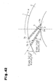
- Fig. 42 is a horizontal cross-sectional view showing the structure of a main part of a testing example of the centrifugal blower of the eighth embodiment;
- Fig. 43 is a graph showing the relationship between the performance and the number of vanes in the testing example of the centrifugal blower of the eighth embodiment;
- Fig. 44 is a vertical half-sectional view of a testing example showing the structure of the centrifugal blower of the eighth embodiment;
- Fig. 45 is a horizontal cross-sectional view showing the structure of a centrifugal blower according to a ninth embodiment;
- Fig. 46 is a vertical cross-sectional view showing the structure of the centrifugal blower of the ninth embodiment;
- Fig. 47 is a horizontal cross-sectional view showing the structure of a centrifugal blower according to a tenth embodiment;
- Fig. 48 is a vertical cross-sectional view showing the structure of the centrifugal blower of the tenth embodiment;
- Fig. 49 is a horizontal cross-sectional view showing the structure of a main part in a testing example of the centrifugal blower of the tenth embodiment;
- Fig. 50 is a graph showing the relationship between the performance and the number of vanes in the testing example of the centrifugal blower of the tenth embodiment;
- Fig. 51 is a horizontal cross-sectional view showing the structure of a centrifugal blower according to an eleventh embodiment;
- Fig. 52 is a vertical cross-sectional view showing the structure of the centrifugal blower of the eleventh embodiment;
- Fig. 53 is a horizontal cross-sectional view showing the structure of a centrifugal blower according to a twelfth embodiment;
- Fig. 54 is a vertical cross-sectional view showing the structure of the centrifugal blower of the twelfth embodiment;
- Fig. 55 is a vertical half-sectional view showing the structure of a centrifugal blower according to a thirteenth embodiment;
- Fig. 56 is a vertical half-sectional view showing the structure of a main part in the centrifugal blower of the thirteenth embodiment;
- Fig. 57 is a horizontal cross-sectional view showing the structure and operation of the main part in the centrifugal blower of the thirteenth embodiment;
- Fig. 58 is horizontal cross-sectional view showing the structure and operation of the main part in the centrifugal blower of the thirteenth embodiment;
- Fig. 59 is a vertical half-sectional view showing the structure of a centrifugal blower according to a fourteenth embodiment; and
- Fig. 60 is a horizontal cross-sectional view showing the structure and operation of a main part in the centrifugal blower of the fourteenth embodiment.
BEST MODE FOR CARRYING OUT THE INVENTION
-
Several preferred embodiments of the present invention will be described in detail with reference to the accompanying drawings.
(First Embodiment)
-
Figs. 1 to 6 illustrate a centrifugal blower X1 and an air conditioner Z1 according to a first embodiment of the present invention.
-
As shown in Figs. 1 and 2, the centrifugal blower X1 is provided with an impeller 1 including a disk-shaped hub 2 with a central portion to which a rotation shaft 4a of a motor 4 is connected and a plurality of vanes 3 arranged on the peripheral portion of the hub 2 at predetermined intervals in the circumferential direction. A bellmouth 5 having an air intake port 6 is located at the air intake side of the impeller 1.
-
As shown in Fig. 2, the impeller 1 is of a sweep back vane type (i.e., a turbo fan type) in which the front rim of each vane is inclined toward the front in the rotational direction, that is, an outer diameter end 3b of each vane 3 is located rearward from an inner diameter end 3a of the vane 3 relative to the rotational direction M of the impeller 1. With this structure, the ratio of static pressure increase occupies a large proportion in the total pressure increase of the impeller. This eliminates the need for a spiral scroll.
-
A recess 2a is formed in the central portion of the hub 2 to house the motor 4. A motor fixing portion 7 is used to fix the motor 4. A bearing boss 8 rotatably supports the rotation shaft 4a of the motor 4. A reinforcing ring 9 connects axial distal ends of the vanes 3.
-
The air intake port 6 of the bellmouth 5 has an inner diameter D0 that is set to be greater than an inner diameter D1 of the vanes 3 of the impeller 1. A circulation space S is formed at the rear side (i.e., the peripheral side) of the bellmouth 5 to ensure that a circulating flow f2 is easily generated in a manner that it flows out of the outlet side of the impeller 1 and is then drawn back into the impeller 1 through the rear side of the air intake port 6 in the bellmouth 5.
-
The air intake port 6 of the bellmouth 5 may have a straight shape as shown in Fig. 3(A), a wedge shape as shown in Fig. 3(B), or a flared shape as shown in Fig. 3(C).
-
In the present embodiment, when the inner diameter of the air intake port 6 of the bellmouth 5 is represented by D0, the inner diameter of the vanes 3 of the impeller 1 is represented by D1, and the outer diameter of the vanes 3 is represented by D2, these dimensions are set to satisfy O<(D0-D1)/(D2-D1)<0.6. There are ten vanes 3.
-
The operation and advantages of the above centrifugal blower will now be described. In the above structure, circulating flow f2 is generated around the reinforcing rib 9 so as to flow out of the outlet side of the impeller 1 and then be drawn back into the impeller 1 through the rear side of the air intake port 6 in the bellmouth 5. Accordingly, a main air flow f1 passing across the vanes 3 after being drawn into from the air intake port 6 is drawn towards the distal ends of the vanes 3 by the circulating flow f2. This improves the air speed distribution in the exit portions of the vanes 3, enhances the aerodynamic performance, and lowers the operational noise. Moreover, since no shroud is required, the integral molding of the impeller 1 is enabled. This lowers costs and provides high mass productivity.
-
Further, in the present embodiment, when the inner diameter of the air intake port 6 of the bellmouth 5 is represented by D0, the inner diameter of the vanes 3 of the impeller 1 is represented by D1, and the outer diameter of the vanes 3 is represented by D2, the dimensions are set to satisfy 0<k=(D0-D1)/(D2-D1)<0.6. This lowers the minimum specific noise Ks low as shown in Fig. 4, enhances the aerodynamic performance, and lowers the operational noise.
-
When 0≥k=(D0-D1)/(D2-D1) is satisfied, as shown in Fig. 5(A), the front distal portions of the vanes 3 do not function effectively and inhibits the enhancement of the aerodynamic performance. When k=(D0-D1)/(D2-D1)≥0.6 is satisfied, as shown in Fig. 5(B), a reversed flow f' generated at the front distal portions of the vanes 3 will becomes strong, while the circulating flow f2 at the rear distal portions of the vanes 3 will become weak. This also inhibits the enhancement of the aerodynamic performance.
-
With D1 representing the inner diameter of the vanes 3, D2 representing the outer diameter of the vanes 3, and D0 representing the inner diameter of the air intake port 6A in the centrifugal blower X1 of this embodiment, a microphone 12 located 45 degrees to the front and one meter away from the intake center Q of the air intake port 6 was used to check changes in the minimum specific noise Ks with respect to a variable k=(D0-D1)/(D2-D1). Fig. 4 shows the results obtained. It can be seen from the results that satisfactory operational noise characteristics were obtained in the range 0<k<0.6.
-
Fig. 6 shows a ceiling-embedded air conditioner Z1 incorporating the centrifugal blower X1 of this embodiment.
-
In this case, a heat exchanger 15 and the centrifugal blower X1 are arranged in an air duct 14 for air flow W that is formed in a casing 13. The motor fixing portion 7 for fixing the motor 4 is formed integrally with a top plate 13a of the casing 13. This air conditioner Z1 includes an intake grille 16, an air filter 17, a drain pan 18, and an air outlet port 19.
-
This structure allows the centrifugal blower X1 to effectively exhibit its advantageous effects. This greatly contributes to enhancement in the performance of the air conditioner Z1 and reduction in costs. Additionally, the optimum diameter for the air intake port 6 may be set to be greater than that of a conventional one. This suppresses pressure loss in the air filter 17 or the like.
(Second Embodiment)
-
Figs. 7 and 11 respectively show a centrifugal blower X2 and an air conditioner Z2 according to a second embodiment of the present invention.
-
In this case, the impeller 1 in the centrifugal blower X2 includes a ring body 20, which has a predetermined width H in the centrifugal direction, in lieu of the reinforcing ring 9 of the first embodiment. In other respects, the structure and effects of the second embodiment are the same as those of the first embodiment. Thus, such parts will not be described.
-
The ring body 20 may take various shapes as shown in Figs. 8(A) to 8(L). The following descriptions are only examples, and it is obvious that the ring body 20 may take other shapes that are not shown in the drawings.
-
As shown in Fig. 8(A), the ring body 20 may be joined to the axial end surfaces of the vanes 3. As shown in Fig. 8(B), the ring body 20 may be attached to be inclined away from the hub. As shown in Fig. 8 (C), the ring body 20 may be attached to be inclined toward the hub. As shown in Fig. 8(D), the centrifugal end of the ring body 20 may be an arcuate surface 20a. As shown in Fig. 8(E), the ring body 20 may have a centrifugal end formed by an arcuate surface 20a and the entire ring body 20 may be curved away from the hub. In this case, the Coanda effect enhances the generation of the circulating flow f2.
-
As shown in Fig. 8(F), the surface of the ring body 20 opposite the hub has a recess 20b. In this case, negative pressure is generated within the recess 20b to enhance generation of the circulating flow f2. As shown in Fig. 8(G), the surface of the ring body 20 opposite the hub may have a recess 20b, and the ring body 20 may be inclined toward the hub. In this case as well as in the case shown in Fig. 8(F), the generation of the circulating flow f2 is enhanced. As shown in Fig. 8(H), the surface of the ring body 20 on the side facing toward the hub may have a recess 20c. In this case, negative pressure is generated within the recess 20c to enhance generation of the circulating flow f2.
-
As shown in Fig. 8(I), the surface of the ring body 20 on the side facing toward the hub may have a recess 20c, and the ring body 20 may be inclined toward the hub. In this case as well as in the case shown in Fig. 8(H), the generation of the circulating flow f2 is enhanced. As shown in Fig. 8(J), the ring body 20 may be formed of a relatively thick member having arcuate surfaces 20d and 20e formed on its attachment end and centrifugal end, respectively. This generates a smooth circulating flow f2.
-
As shown in Fig. 8(K), the ring body 20 may be formed of a relatively thick member having arcuate surfaces 20d and 20e formed on its attachment end and on its centrifugal end, respectively, and the ring body 20 may be inclined toward the hub. In this case as well as in the case shown in Fig. 8(J), a smooth circulating flow f2 is generated.
-
As shown in Fig. 8(L), the hub 2 may include an inclined surface 2b at the region where the vanes 3 are arranged such that the inclined surface 2b is inclined toward the side opposite the vanes, while the ring body 20 may be formed of a relatively thick member having arcuate surfaces 20d and 20e formed on its attachment end and centrifugal end, respectively, and the ring body 20 may be attached to an inclined surface 3c (inclined at a same angle as the inclined surface 2b of the hub 2) formed at the distal end of each vane 3. In this case, during molding, the ring body 20 may be removed from the peripheral side.
-
With D2 representing the outer diameter of the vanes 3 and H representing the width of the ring body 20 in the centrifugal direction in the centrifugal blower X2 of this embodiment, a microphone 12 located 45 degrees to the front and one meter away from the intake center Q of the air intake port 6 was used to check changes in the minimum specific noise Ks with respect to a variable ki=H/D2. Fig. 9 shows the results obtained.
-
It can be seen from the above results that satisfactory operational noise characteristics were obtained in the range 0.05<ki<0.225. The range 0.1<ki<0.15 is more preferable. When ki=H/D≤0.05 is satisfied, the effect will be reduced. When ki=H/D≥0.225 is satisfied, the formation of circulating flow will be adversely affected and weaken the circulating flow at the rear distal portions of the vanes 3. This inhibits enhancement of the aerodynamic performance.
-
With L representing the distance between the ring body 20 and the bellmouth 5, changes in the minimum specific noise Ks with respect to a variable L/D2 were checked. Fig. 10 shows the results obtained. As seen from the above results, satisfactory operational noise characteristics were obtained in the range L/D2≥0.169.
-
Fig. 11 shows a ceiling-embedded air conditioner Z2 incorporating the centrifugal blower X2 of the second embodiment. In this case, a heat exchanger 15 and the centrifugal blower X2 are arranged in an air duct 14 for air flow W that is formed within a casing 13. A motor fixing portion 7 for fixing a motor 4 is formed integrally with a top plate 13a of the casing 13. The air conditioner Z2 has an intake grille 16, an air filter 17, a drain pan 18, and an air outlet port 19. This structure enables the centrifugal blower X2 to effectively exhibit its advantageous effects. This greatly contributes to enhancement in performance of the air conditioner Z2 and reduction in costs. Additionally, the optimum diameter of the air intake port 6 may be greater than that of a conventional one. This lowers pressure loss in the air filter 17.
-
The centrifugal blower of the above embodiments is applied when the number of the vanes 3 is small (i.e., 5 to 15 vanes).
(Third Embodiment)
-
Figs. 12 to 16 show a centrifugal blower X3 and an air conditioner Z3 according to a third embodiment of the present invention.
-
As shown in Figs. 12 and 13, the centrifugal blower X3 is provided with an impeller 1 including a disk-shaped hub 2 having a central portion to which a rotation shaft 4a of a motor 4 is connected and a plurality of vanes 3 arranged on the peripheral portion of the hub 2 at predetermined intervals in the circumferential direction. A bellmouth 5 having an air intake port 6 is arranged on the air intake side of the impeller 1.
-
As shown in Fig. 13, the impeller 1 is of a sweep back vane type (i.e., a turbo fan type) in which the front rim of each vane is inclined toward the front in the rotational direction, that is, an outer diameter end 3b of each vane 3 is located rearward from an inner diameter end 3a of the vane 3 relative to the rotational direction M of the impeller 1. With this structure, the ratio of static pressure increase occupies a large proportion in the total pressure increase of the impeller. This eliminates the need of a spiral scroll. In the centrifugal blower X3 of this embodiment, the number of vanes 3 is greater (for example, 30 to 50 vanes) than the numbers of vanes in the centrifugal blowers X1 and X2 of the first and second embodiments.
-
A recess 2a is formed in the central portion of the hub 2 for housing the motor 4. A motor fixing portion 7 is used to fix the motor 4. A bearing boss 8 rotatably supports the rotation shaft 4a of the motor 4.
-
Like the second embodiment, the impeller 1 of the third embodiment is provided with a ring body 20 having a predetermined width H in the centrifugal direction. In the third embodiment, the ring body 20 is inclined toward the hub 2 in the centrifugal direction.
-
A circulation space S is formed at the rear side (i.e., the peripheral side) of the bellmouth 5 to ensure that a circulating flow f2 is easily generated in a manner that it flows out of the outlet side of the impeller 1 and is then drawn back into the impeller 1 through the rear side of the air intake port 6 in the bellmouth 5. Like the first embodiment, the air intake port 6 of the bellmouth 5 may take any of a straight shape, a wedge shape, and a flared shape.
-
In this embodiment, when the inner diameter of the air intake port 6 of the bellmouth 5 is represented by D0, the inner diameter of the vanes 3 of the impeller 1 is represented by D1, and the outer diameter of the vanes 3 is represented by D2, the dimensions are set to satisfy -0.3<(D0-D1)/(D2-D1)<0.3. The number of the vanes 3 is 40.
-
The operation and advantages of the above centrifugal blower will now be described.
-
Circulating flow f2 is generated to flow out of the outlet side of the impeller 1 and then be drawn back into the impeller 1 through the rear side of the air intake port 6 in the bellmouth 5. Accordingly, a main air flow f1 passing across the vanes 3 after being drawn into from the air intake port 6 is drawn towards the distal ends of the vanes 3 by the circulating flow f2. This improves the air speed distribution in the exit portions of the vanes 3, enhances the aerodynamic performance, and lowers the operational noise. Moreover, since no shroud is required, the integral molding of the impeller 1 is enabled. This lowers costs and provides high mass productivity.
-
In this third embodiment, when the inner diameter of the air intake port 6 of the bellmouth 5 is represented by D0, the inner diameter of the vanes 3 of the impeller 1 is represented by D1, and the outer diameter of the vanes 3 is represented by D2, the dimensions are set such that -0.3<k=(D0-D1)/(D2-D1)<0.3 is satisfied. As shown in Fig. 14, this lowers the minimum specific noise Ks low, which further enhances the aerodynamic performance, and reduces the operational noise. When -0.3≥k=(D0-D1)/(D2-D1) is satisfied, the front distal portions of the vanes 3 will not function effectively and inhibit the enhancement of the aerodynamic performance. When k=(D0-D1)/(D2-D1)≥0.3 is satisfied, the reversed flow f' generated at the front distal portions of the vanes 3 becomes strong, and the circulating flow f2 at the rear distal portions of the vanes 3 become weak. This inhibits enhancement in the aerodynamic performance.
-
With D1 representing the inner diameter of the vanes 3, D2 representing the outer diameter of the vanes 3, and D0 representing the inner diameter of the air intake port 6 in the centrifugal blower X2 of this embodiment, a microphone 12 located 45 degrees to the front and one meter away from the intake center Q of the air intake port 6 was used to check changes in the minimum specific noise Ks with respect to a variable k=(D0-D1)/(D2-D1). Fig. 14 shows the results obtained. It can be seen from the results that satisfactory operational noise characteristics were obtained in the range -0.3<k<0.3.
-
The relationship between the outer diameter D2 of the vanes 3 and the width H in the centrifugal direction of the ring body 20 in the centrifugal blower X3 is the same as that in the second embodiment. The relationship between the outer diameter D2 of the vanes 3 and the distance L between the ring body 20 and the bellmouth 5 in the centrifugal blower X3 is shown in Fig. 15. The minimum specific noise Ks is lowered and suppressed in the range L/D2≥0.07. When L/D2<0.07 is satisfied, the minimum specific noise Ks increases drastically.
-
When the exit side height B of the vanes 3 in the impeller 1 decreases, fluctuation in the air flow line f1 increases at the exit side of the impeller 1. This eventually causes the circulating flow f2 to obstruct the flow passage between the vanes 3. In such a case, the aerodynamic performance falls sharply as shown by the solid line in Fig. 16, and a hysteresis will occur as shown by the broken line in Fig. 16. This is not irrelevant to the number of the vanes.
-
Therefore, this embodiment is set to satisfy B/D2≥0.113. This setting solves the problem of fluctuation in the air flow line f1 at the exit side of the impeller 1, and provides stable performance as shown by the double-dotted line in Fig. 16. If B/D2<0.113 is satisfied, the air flow line at the exit side of the impeller 1 will greatly fluctuate, and the circulating flow f2 will eventually obstruct the flow passage between the vanes 3 and cause the performance to fall sharply.
-
In the centrifugal blower X3 of the third embodiment, changes in the maximum flow rate coefficient ϕmax (the coefficient when there is no deterioration is defined as reference value=1) with respect to B/D2 was checked. Fig. 17 shows the results obtained. Here, ϕmax=Qmax/60(ΠD2B)u2 is satisfied, where u2=ΠD2N, Qmax represents the fully open air flow (m3/min), and N represents the rotation speed (rpm). It can be seen from the results shown in Fig. 17 that the maximum flow rate coefficient ϕmax is equal to the reference value of one when B/D2≥0.113 is satisfied.
-
Fig. 18 shows a ceiling-embedded air conditioner Z3 incorporating the centrifugal blower X3 of this embodiment. In this case, a heat exchanger 15 and the centrifugal blower X3 are arranged in an air duct 14 for air flow W that is formed within a casing 13. A motor fixing portion 7 is used for fixing a motor 4 is integral with a top plate 13a of the casing 13. The air conditioner Z3 has an intake grille 16, an air filter 17, a drain pan 18, and an air outlet port 19. This structure enables the centrifugal blower X3 to effectively exhibit its advantageous effects. This greatly contributes to enhancement in performance of the air conditioner Z2 and reduction in costs. Additionally, the optimum diameter of the air intake port 6 may be greater than that of a conventional one. This lowers pressure loss in the air filter 17.
-
Modifications of the centrifugal blower X3 of the third embodiment will be described.
(Modification I)
-
As shown in Fig. 19, the tip side end of each vane 3 in the impeller 1 may be inclined at substantially the same inclination angle as that of the ring body 20. In this case as well, the relationship among D0, D1, D2, H, L, and B is the same as described above.
(Modification II)
-
As shown in Fig. 20, the tip side end of each vane 3 in the impeller 1 may be inclined at substantially the same inclination angle as that of the ring body 20, with the inlet side end of each vane 3 inclined in the centripetal direction of the impeller 1 toward the hub. In this case as well, the relationship among D0, D1, D2, H, L, and B is the same as described before.
(Modification III)
-
As shown in Fig. 21, the tip side end of each vane 3 in the impeller 1 may be inclined at substantially same inclination angle as an inclination angle of the ring body 20, with the inlet side end of each vane 3 inclined in the centripetal direction of the impeller 1 toward the hub with serrations 21 formed in the inlet side end. This structure prevents the formation of a boundary layer on the vane surfaces. Thus, the air flow noise is reduced. In this case as well, the relationship among D0, D1, D2, H, L, and B is the same as described before.
(Fourth Embodiment)
-
Fig. 22 shows a centrifugal blower X4 according to a fourth embodiment of the present invention. In this embodiment, the outer diameter D3 of a hub 2 forming an impeller 1 is set to be smaller than the outer diameter D2 of vanes 3. Accordingly, an opening 22 is formed in the hub side of the peripheral portion on the vanes 3. This reduces the flow resistance of the air blown out of the vanes 3 when using a diagonal diffuser 23, which will be described later (see Fig. 29). In other respects, the structure and effects of the fourth embodiment are the same as those of the third embodiment and therefore will not be described.
-
In the fourth embodiment as well as in the third embodiment, when the exit side height B of the vanes 3 in the impeller 1 decreases, fluctuation in the air flow line f1 increases at the exit side of the impeller 1. This eventually causes the circulating flow f2 to obstruct the flow passage between the vanes 3. In such a case, the aerodynamic performance falls sharply as shown by the solid line in Fig. 16, and a hysteresis will occur as shown by the broken line in Fig. 16. This is not irrelevant to the number of the vanes.
-
Therefore, this embodiment is set to satisfy B/D2≥0.08. The reason the upper limit of B/D2 is less than that in the third embodiment is in that the opening 22 is formed in the peripheral portion of the hub-side of the vanes 3. This setting solves the problem of fluctuation in the air flow line f1 at the exit side of the impeller 1, and provides stable performance as shown by the double-dotted line in Fig. 15. If B/D2<0.08 is satisfied, the air flow line at the exit side of the impeller 1 will greatly fluctuate, and the circulating flow f2 will eventually obstruct the flow passage between the vanes 3 and cause the performance to fall sharply.
-
In the centrifugal blower X3 of this embodiment, changes in the maximum flow rate coefficient ϕmax (the coefficient when there is no deterioration is defined as reference value=1) with respect to B/D2 was checked. Fig. 23 shows the results obtained. Here, ϕmax=Qmax/60(ΠD2B)u2 is satisfied, where u2=ΠD2N, Qmax represents the fully open air flow (m3/min), and N represents the rotation speed (rpm). It can be seen from the results shown in Fig. 23 that the maximum flow rate coefficient ϕmax is equal to the reference value of one when B/D2≥0.08 is satisfied.
-
Modifications of the centrifugal blower X4 of the fourth embodiment will now be described.
(Modification I)
-
As shown in Fig. 24, the tip side end of each vane 3 of the impeller 1 may be inclined at substantially the same inclination angle as that of the ring body 20. In this case as well, the relationship among D0, D1, D2, H, L, and B is the same as described before.
(Modification II)
-
As shown in Fig. 25, the tip side end of each vane 3 in the impeller 1 may be inclined at substantially the same inclination angle as that of the ring body 20, with the inlet side end of each vane 3 inclined in the centripetal direction of the impeller 1 toward the hub. In this case as well, the relationship among D0, D1, D2, H, L, and B is the same as described before.
(Modification III)
-
As shown in Fig. 26, the tip side end of each vane 3 in the impeller 1 may be inclined at a substantially same inclination angle as an inclination angle of the ring body 20, and the inlet side end of each vane 3 is inclined in the centripetal direction of the impeller 1 toward the hub with serrations 21 is formed in the inlet side end. This structure prevents the formation of a boundary layer on the vane surfaces. Thus, the air flow noise is reduced. In this case as well, the relationship among D0, D1, D2, H, L, and B is the same as described before.
(Modification IV)
-
As shown in Fig. 27, the impeller 1 may be of a diagonal flow fan type in which the peripheral portion of the hub 2 (that is, the region where the vanes 3 are arranged) is inclined. In this case as well, the relationship among D0, D1, D2, H, L, and B is the same as described before.
(Modification V)
-
As shown in Fig. 28, the impeller 1 may be of a diagonal flow fan type in which the peripheral portion of the hub 2 (that is, the region where the vanes 3 are arranged) is inclined, and the inlet side end of each vane 3 is inclined in the centripetal direction of the impeller 1 towards the hub. In this case as well, the relationship among D0, D1, D2, H, L, and B is the same as described before.
-
It is obvious that the centrifugal blower X4 of the fourth embodiment may be incorporated in an air conditioner.
(Fifth Embodiment)
-
Fig. 29 shows a centrifugal blower X5 according to a fifth embodiment of the present invention. In this embodiment, the outer diameter D3 of a hub 2 forming an impeller 1 is set to be smaller than the outer diameter D2 of vanes 3, and a diagonal centrifugal diffuser 23 is arranged on the outlet side of the impeller 1 so that an air flow from the impeller 1 is guided from the obliquely rear side in the centrifugal direction. In this structure, an opening 22 is formed in the hub side of the peripheral portion of the vanes 3. This reduces the air flow resistance of the air blown out from the vanes 3, enables the dynamic pressure of the air blown out from the impeller 1 to efficiently return to the static pressure, and greatly contributes to the enhancement of the performance (i.e., high efficiency and low noise). In other respects, the structure and effects of the fifth embodiment are the same as those of the third embodiment and therefore will not be described.
-
Modifications of the centrifugal blower X5 of the fifth embodiment will now be described.
(Modification I)
-
As shown in Fig. 30, the tip side end of each vane 3 in the impeller 1 may be inclined at substantially the same inclination angle as that of the ring body 20. In this case as well, the relationship among D0, D1, D2, H, L, and B is the same as described before.
(Modification II)
-
As shown in Fig. 31, the tip side end of each vane 3 in the impeller 1 may be inclined at substantially the same inclination angle as that of the ring body 20, with the inlet side end of each vane 3 inclined in the centripetal direction of the impeller 1 towards the hub. In this case as well, the relationship among D0, D1, D2, H, L, and B is the same as described before.
-
The centrifugal blowers of the third to the fifth embodiments employ a large number of the vanes 3 (i.e., 30 to 50 vanes).
-
It is obvious that the centrifugal blower X4 of to this embodiment may be incorporated in an air conditioner. It is also obvious that similar effects may be obtained by using a spiral casing.
(Modification III)
-
The centrifugal blower X5 shown in Fig. 32 is characterized in that a diagonal centrifugal diffuser 23 similar to those shown in Figs. 29 to 31 is provided in the structure of the impeller and the bellmouth of the centrifugal blower X3 of the third embodiment described above.
-
In this case, as shown in Fig. 32, the air speed distribution at the exit portion of the vanes 3 of the impeller 1 becomes greater at the intake side due to the guiding function of the ring body 20, and relatively small at the side of the hub 2. However, afterwards, the speed of the air blown out from the side of the hub 2 is increased in the diagonal direction by the air flow passing through the diagonal diffuser passage that is deflected toward the side of the hub 2 and ultimately blown out from the outlet port in the centrifugal direction. Thus, the speed of the air blown out from the outlet port in the centrifugal direction becomes uniform throughout. This improves the fan efficiency and effectively improves the noise reduction performance.
-
In order to check this effect, for example, the centrifugal blower X3 of modification I of the third embodiment shown in Fig. 19 (Fig. 33) is compared with a conventional shrouded centrifugal blower provided with the diagonal centrifugal diffuser 23 (Fig. 34) with regard to the air speed distribution. The comparison result is as described below.
-
In the conventional shrouded centrifugal blower shown in Fig. 34, the air flow drawn into the air intake port 6 of the bellmouth 5 is deflected toward the hub 2. This results in the air speed distribution at the exit portion of the vanes 3 being decreased at the air intake port 6 and increased at the side of the hub 2. Thus, the air flow is greatly deflected toward the hub 2.
-
Moreover, the air flow deflected toward the hub 2 is further deflected rearward by passing through the diagonal passage in the diagonal centrifugal diffuser 23 and being directly blown out in the centrifugal direction. Thus, the air speed distribution of the ultimately blown out air flow is greatly deflected toward the rear side.
-
In contrast, the centrifugal blower X3 of the modification I of the third embodiment shown in Fig. 33 is shroudless and has the ring body 20 provided on the peripheral portion of the axial distal ends of the vanes 3. The main air flow f1 is drawn toward the distal end side of the vanes 3 by the circulating flow f2 formed by the ring body 20. This significantly improves the air speed distribution in the exit portion of the vanes 3. However, the air speed distribution of the blown out air in the ring body 20 is great, and the air speed distribution is not necessarily uniform when the outlet port is viewed as a whole.
-
In contrast, in the case of the centrifugal blower X5 of the modification III of the fifth embodiment, which has the diagonal centrifugal diffuser 23 of which passage shape changes in the radial direction, the air speed distribution of the air ultimately blown out from the outlet port in the centrifugal direction becomes uniform over the entirety as shown in Fig. 32. Accordingly, as shown in Fig. 35, the noise reduction effect is much greater than that of the conventional shrouded centrifugal blower shown in Fig. 34.
(Sixth Embodiment)
-
Figs. 36 and 37 show an impeller of a centrifugal blower according to a sixth embodiment of the present invention.
-
As shown in Figs. 36 and 37, this centrifugal blower impeller 1 includes, for example, a disk-shaped hub 2 having a central portion to which a rotation shaft 4a of a motor 4 is connected and a plurality of vanes 3 arranged on the peripheral portion of the hub 2 at predetermined intervals in the circumferential direction.
-
Each vane 3 of the impeller 1 has an inner diameter end 3a, or front rim, inclined forward in the rotational direction, and a outer diameter end 3b, or rear rim, located rearward from the inner diameter end 3a in the rotational direction M of the impeller 1. Thus, the impeller 1 is of a sweep back vane type (so called turbo fan type) in which a camber line protrudes in the rotational direction.
-
The number of vanes 3 of the impeller 1 is set to, for example, 20 to 50. A ring body 20 having a predetermined width H in the centrifugal direction is attached to the peripheral portion of the vane ends on the side of a bellmouth. In this embodiment, the end of the ring body 20 and the end of each vane 3 on the side of the bellmouth are inclined toward the hub 2 in the centrifugal direction like in Fig. 24. In other respects, the structure of the sixth embodiment is basically the same as the above embodiments.
-
The centrifugal blower of this embodiment, which has the impeller 1 as described above formed in combination with a bellmouth 5 like those of the above embodiments without a shroud, also has the advantages described below that are similar to those of the above embodiments.
-
Specifically, the presence of the ring body 20 causes the generation of the circulating flow f2 that flows out from the outlet side of the impeller 1, flows back into the impeller 1, and passes the rear side of the air intake port 6 of the bellmouth 5. Therefore, main air flow f1 passing across the vanes 3 is effectively drawn toward the distal ends of the vanes 3 by the circulating flow f2. As a result, the air speed distribution in the exit portion of the vanes 3 is improved uniformly. This enhances the aerodynamic performance and reduces operational noise.
-
Moreover, since no shroud is required, the impeller 1 can be molded integrally. This simplifies the structure, reduces costs, and improves mass productivity.
(Seventh Embodiment)
-
Figs. 38 and 39 show an impeller of a centrifugal blower according TO a seventh embodiment of the present invention. As shown in Figs. 38 and 39, this centrifugal blower impeller 1 includes, for example, a disk-shaped hub 2 having central portion to which a rotation shaft 4a of a motor 4 is connected and a plurality of vanes 3 arranged on the peripheral portion of the hub 2 at predetermined intervals in the circumferential direction.
-
Each vane 3 of the impeller 1 has an inner diameter end 3a, or a front rim, inclined forward in the rotational direction and an outer diameter end 3b, or rear rim located rearward from the inner diameter end 3a in the rotational direction M of the impeller 1. Thus, the impeller 1 is of a sweep back vane type (so called turbo fan type) in which a camber line protrudes in the rotational direction.
-
The number of vanes 3 of the impeller 1 is set, for example, to 20 to 50. A ring body 20 having a predetermined width H in the centrifugal direction is attached to the peripheral portion of the vane ends on the side of a bellmouth. In this embodiment, the end of the ring body 20 and the end of each vane 3 on the side of the bellmouth are inclined toward the hub 2 along the centrifugal direction, like in Fig. 24. In other respects, the structure of the seventh embodiment is basically the same as the above embodiments.
-
The centrifugal blower of this embodiment, which has the impeller 1 as described above formed in combination with a bellmouth 5 like those of the above embodiments without a shroud, also has the advantages described below that are similar to those of the above embodiments.
-
Specifically, the presence of the ring body 20 causes the generation of the circulating flow f2 that flows out from the outlet side of the impeller 1, flows back into the impeller 1, and passes the rear side of the air intake port 6 of the bellmouth 5. Therefore, main air flow f1 passing across the vanes 3 is effectively drawn toward the distal ends of the vanes 3 by the circulating flow f2. As a result, the air speed distribution in the exit portion of the vanes 3 is improved uniformly. This enhances the aerodynamic performance and reduces operational noise.
-
Moreover, since no shroud is required, the impeller 1 can be molded integrally. This simplifies the structure, reduces costs, and improves mass productivity.
(Eighth Embodiment)
-
Figs. 40 and 41 show an impeller of a centrifugal blower according to a seventh embodiment of the present invention. As shown in Figs. 40 and 41, this centrifugal blower impeller 1 includes, for example, a disk-shaped hub 2 having a central portion to which a rotation shaft 4a of a motor 4 is connected and a plurality of vanes 3 arranged on the peripheral portion of the hub 2 at predetermined intervals in the circumferential direction.
-
Each vane 3 of the impeller 1 has an inner diameter end 3a, or a front rim, inclined forward in the rotational direction, and an outer diameter end 3b, or a rear rim, located rearward from the inner diameter end 3a in the rotational direction M of the impeller 1. Thus, the impeller 1 is of a sweep back vane type (so called turbo fan type) in which a camber line protrudes in the rotational direction.
-
The number of vanes 3 of the impeller 1 is set to, for example, a large value from 20 to 50. A ring body 20 having a predetermined width H in the centrifugal direction is attached to the peripheral portion of the vane ends at the side of a bellmouth. In this embodiment, the end of the ring body 20 and the ends of the vanes 3 at the side of the bellmouth are inclined toward the hub 2 along the centrifugal direction like those in Fig. 24. In other respects, the structure of the eighth embodiment is basically the same as the above embodiments.
-
The centrifugal blower of this embodiment, which has the impeller 1 as described above formed in combination with a bellmouth 5 like those of the above embodiments without a shroud, also has the advantages described below that are similar to those of the above embodiments.
-
Specifically, the presence of the ring body 20 causes the generation of the circulating flow f2 that flows out from the outlet side of the impeller 1, flows back into the impeller 1, and passes the rear side of the air intake port 6 of the bellmouth 5. Therefore, the main air flow f1 passing across the vanes 3 is effectively drawn toward the distal ends of the vanes 3 by the circulating flow f2. As a result, the air speed distribution in the exit portion of the vanes 3 is improved uniformly. This enhances the aerodynamic performance and reduces operational noise. Moreover, since no shroud is required, the impeller 1 can be molded integrally. This simplifies the structure, reduces costs, and improves mass productivity.
-
In a centrifugal blower having an impeller as described above employing sweep back vanes having a straight camber line and including outer diameter ends 3b located rearward from inner diameter ends 3a in the rotational direction M of the impeller 1, the maximum static pressure efficiency ratio (reference value of 1.0) and minimum specific noise level ratio (reference value level of ±0) were measured using the number of vanes as parameters. The measurement results obtained are shown in the graph of Fig. 43.
-
The centrifugal blower used for the measurement has an impeller formed as shown Figs. 40 and 41. Each vane 3 has an inlet angle θ1 of 25 degrees and an outlet angle θ2 of 50 degrees as shown in Fig. 42. An inlet height B1 and an outlet height B2 of each vane 3 are 35 mm and 30 mm, respectively. An inner diameter D0 of the air intake port 6 of the bellmouth 25 is 130 mm, and an inner diameter D1 and an outer diameter D2 of the vane 3 are 110 mm and 160 mm, respectively.
-
From the measurement results shown in Fig. 43, it can be determined that the performance deteriorates when the number of the vanes 3 is less than 20 because the circulating flow f2 enters deeply into the vanes 3 as shown by f2' in Fig. 44. On the other hand, when the number of vanes is greater than 50, the performance also deteriorates because the intervals P between the front distal portions of the vanes 3 become too narrow.
-
In contrast, the problems as described above seldom occur when the number of vanes 3 is 20 to 50. Further, the static pressure efficiency ratio is high, and the specific noise level ratio is minimized. Thus, it is apparent that the noise reduction performance is effectively improved while the fan efficiency is increased.
-
Similar improvements in performance related to the number of vanes can be expected for the above sixth and seventh embodiments and for a twelfth embodiment described later.
(Ninth Embodiment)
-
Figs. 45 and 46 show a centrifugal blower according to a ninth embodiment of the present invention. As shown in Figs. 45 and 46, this centrifugal blower has an impeller 1 which includes, for example, a disk-shaped hub 2 having a central portion to which a rotation shaft 4a of a motor 4 is connected and a plurality of vanes 3 arranged on the peripheral portion of the hub 2 at predetermined intervals in the circumferential direction.
-
The impeller 1 is of a radial vane type (so called a radial plate fan type) in which each vane 3 has an inner diameter end 3a, or a front rim, that is neither inclined toward the front nor the rear in the rotational direction M and has a straight camber line extending in the radial direction.
-
The number of vanes 3 of the impeller 1 is set to a large value, for example, 30 to 72, and a ring body 20 having a predetermined width H in the centrifugal direction is arranged on the peripheral portion of the ends of the vanes at the bellmouth side. In this embodiment, the end of the ring body 20 and the ends of the vanes 3 at the side of the bellmouth are inclined toward the hub 2 in the centrifugal direction, like those shown in Fig. 44. In other respects, the structure of the ninth embodiment is basically the same as the above embodiments.
-
The centrifugal blower of this embodiment, which has the impeller 1 as described above formed in combination with a bellmouth 5 like those of the above embodiments without a shroud, also has the advantages described below that are similar to those of the above embodiments.
-
Specifically, the presence of the ring body 20 causes the generation of the circulating flow f2 that flows out from the outlet side of the impeller 1, flows back into the impeller 1, and passes the rear side of the air intake port 6 of the bellmouth 5. Therefore, main air flow f1 passing across the vanes 3 is effectively drawn toward the distal ends of the vanes 3 by the circulating flow f2. As a result, the air speed distribution in the exit portion of the vanes 3 is improved uniformly. This enhances the aerodynamic performance and reduces operational noise.
-
Moreover, since no shroud is required, the impeller 1 can be molded integrally. This simplifies the structure, reduces costs, and improves mass productivity.
(Tenth Embodiment)
-
Figs. 47 and 48 show an impeller of a centrifugal blower according to a tenth embodiment of the present invention. As shown in Figs. 47 and 48, this centrifugal blower impeller 1 includes, for example, a disk-shaped hub 2 having a central portion to which a rotation shaft 4a of a motor 4 is connected and a plurality of vanes 3 arranged on the peripheral portion of the hub 2 at predetermined intervals in the circumferential direction.
-
The impeller 1 is of a radial vane type (first modification of the radial plate fan type described above) in which each vane 3 has an inner diameter end 3a, or a front rim, that is neither inclined toward the front nor the rear in the rotational direction M and has a camber line slightly inclined toward the rear in the rotational direction M.
-
The number of vanes 3 of the impeller 1 is set to a large value of, for example, 30 to 72, and a ring body 20 having a predetermined width H in the centrifugal direction is arranged on the peripheral portion of the ends of the vanes at the bellmouth side. In this embodiment, the end of the ring body 20 and the ends of the vanes 3 at the side of the bellmouth are inclined toward the hub 2 in the centrifugal direction like in Fig. 44. In other respects, the structure of the tenth embodiment is basically the same as the above embodiments.
-
The centrifugal blower of this embodiment, which has the impeller 1 as described above formed in combination with a bellmouth 5 like those of the above embodiments without a shroud, also has the advantages described below that are similar to those of the above embodiments.
-
Specifically, the presence of the ring body 20 causes the generation of the circulating flow f2 that flows out from the outlet side of the impeller 1, flows back into the impeller 1, and passes the rear side of the air intake port 6 of the bellmouth 5. Therefore, main air flow f1 passing across the vanes 3 is effectively drawn toward the distal ends of the vanes 3 by the circulating flow f2. As a result, the air speed distribution in the exit portion of the vanes 3 is improved uniformly. This enhances the aerodynamic performance and reduces operational noise. Moreover, since no shroud is required, the impeller 1 can be molded integrally. This simplifies the structure, reduces costs, and improves mass productivity.
-
For the centrifugal blower of the tenth embodiment, the maximum static pressure efficiency ratio (reference value of 1.0) and minimum specific noise level ratio (reference value level of ±0) were measured by using the numbers of the vanes as a parameter. The measurement results obtained are shown in the graph of Fig. 50.
-
The centrifugal blower used for the measurement has an impeller formed as shown Figs. 47 and 48. Each vane 3 has an inlet angle θ1 of 90 degrees and an outlet angle θ2 of 75 degrees as shown in Fig. 49. An inlet height B1 and an outlet height B2 of each vane 3 are 25 mm and 20 mm, respectively. An inner diameter D0 of the air intake port 6 of the bellmouth 25 is 130 mm, and an inner diameter D1 and an outer diameter D2 of the vanes 3 are 130 mm and 150 mm, respectively.
-
From the measurement results shown in Fig. 53, it can be determined that the performance deteriorates when the number of the vanes 3 is less than 30 because the circulating flow f2 enters deeply into the vanes 3 as shown by f2' in Fig. 44. On the other hand, when the number of vanes is greater than 72, the performance also deteriorates because the intervals P between the front distal portions of the vanes 3 become too narrow.
-
In contrast, the problems as described above seldom occur when the number of vanes 3 is 30 to 72. Further, the static pressure efficiency ratio is high, and the specific noise level ratio is minimized. Thus, it is apparent that the noise reduction performance is effectively improved while the fan efficiency is increased.
-
Similar improvements in performance related to the number of vanes can be expected for the ninth embodiment described above and eleventh embodiment described below.
(Eleventh Embodiment)
-
Figs. 51 and 52 show an impeller of a centrifugal blower according to a tenth embodiment of the present invention. As shown in Figs. 51 and 52, this centrifugal blower impeller 1 includes, for example, a disk-shaped hub 2 having a central portion to which a rotation shaft 4a of a motor 4 is connected and a plurality of vanes 3 arranged on the peripheral portion of the hub 2 at predetermined intervals in the circumferential direction.
-
The impeller 1 is of a radial vane type (second modification of the radial plate fan type described above) in which each vane 3 has an inner diameter end 3a, or a front rim that is neither inclined toward the front nor the rear in the rotational direction M and a camber line slightly inclined toward the front in the rotational direction M.
-
The number of vanes 3 of the impeller 1 is set to a large value of, for example, 30 to 72 like in the above embodiments, and a ring body 20 having a predetermined width H in the centrifugal direction is arranged on the peripheral portion of the ends of the vanes at the bellmouth side. In this embodiment, the end of the ring body 20 and the ends of the vanes 3 on the side of the bellmouth are inclined toward the hub 2 in the centrifugal direction like in Fig. 44. In other respects, the structure of the eleventh embodiment is basically the same as the above embodiments.
-
The centrifugal blower of this embodiment, which has the impeller 1 as described above formed in combination with a bellmouth 5 like those of the above embodiments without a shroud, also has the advantages described below that are similar to those of the above embodiments.
-
Specifically, the presence of the ring body 20 causes the generation of the circulating flow f2 that flows out from the outlet side of the impeller 1, flows back into the impeller 1, and passes the rear side of the air intake port 6 of the bellmouth 5. Therefore, the main air flow f1 passing across the vanes 3 is effectively drawn toward the distal ends of the vanes 3 by the circulating flow f2. As a result, the air speed distribution in the exit portion of the vanes 3 is improved uniformly. This enhances the aerodynamic performance and reduces operational noise.
-
Moreover, since no shroud is required, the impeller 1 can be molded integrally. This simplifies the structure, reduces costs, and improves mass productivity.
(Twelfth Embodiment)
-
Figs. 53 and 54 show an impeller of a centrifugal blower according to a twelfth embodiment of the present invention.
-
As shown in Figs. 53 and 54, this centrifugal blower impeller 1 includes, for example, a disk-shaped hub 2 having a central portion to which a rotation shaft 4a of a motor 4 is connected and a plurality of vanes 3 arranged on the peripheral portion of the hub 2 at predetermined intervals in the circumferential direction.
-
The impeller 1 is of a radial vane type (radial tip fan type with an outlet angle θ2 of about 90 degrees) in which each vane 3 has a curved camber line recessed in the rotational direction.
-
The number of the vanes 3 of the impeller 1 is set to, for example, 20 to 50 like in the sixth, seventh, and eighth embodiments, and a ring body 20 having a predetermined width H in the centrifugal direction is arranged on the peripheral portion of the ends of the vanes at the bellmouth side. In this embodiment, the end of the ring body 20 and the ends of the vanes 3 on the side of the bellmouth are inclined toward the hub 2 in the centrifugal direction like in Fig. 44. In other respects, the structure of the twelfth embodiment is basically the same as the above embodiments.
-
The centrifugal blower of this embodiment, which has the impeller 1 as described above formed in combination with a bellmouth 5 like those of the above embodiments without a shroud, also has the advantages described below that are similar to those of the above embodiments.
-
Specifically, the presence of the ring body 20 causes the generation of the circulating flow f2 that flows out from the outlet side of the impeller 1, flows back into the impeller 1, and passes the rear side of the air intake port 6 of the bellmouth 5. Therefore, main air flow f1 passing across the vanes 3 is effectively drawn toward the distal ends of the vanes 3 by the circulating flow f2. As a result, the air speed distribution in the exit portion of the vanes 3 is improved uniformly. This enhances the aerodynamic performance and reduces operational noise.
-
Moreover, since no shroud is required, the impeller 1 can be molded integrally. This simplifies the structure, reduces costs, and improves mass productivity.
(Thirteenth Embodiment)
-
Figs. 55 to 58 show the structure of main parts of a centrifugal blower according to a thirteenth embodiment of the present invention.
-
As shown in Figs. 55 to 58, this centrifugal blower impeller 1 includes, for example, a disk-shaped hub 2 having central portion to which a rotation shaft 4a of a motor 4 is connected and a plurality of vanes 3 arranged on the peripheral portion of the hub 2 at predetermined intervals in the circumferential direction.
-
The vanes 3 of this impeller 1 are either forward inclined type vanes 3A (Fig. 57) in which the vane 3 is entirely inclined toward the front at a predetermined angle in the rotational direction M or rearward inclined type vanes 3B (Fig. 58) inclined opposite the forward inclined type vanes.
-
Regardless of the type, the number of vanes 3 of the impeller 1 is set to a large value of, for example, 30 to 72, and a ring body 20 having a predetermined width H in the centrifugal direction is arranged on the peripheral portion of the ends of the vanes at the bellmouth side. In this embodiment, the end of the ring body 20 and the ends of the vanes 3 on the side of the bellmouth are inclined toward the hub 2 along the centrifugal direction, as viewed from Fig. 55. In other respects, the structure of the thirteenth embodiment is basically the same as the above embodiments.
-
The centrifugal blower of this embodiment, which has the impeller 1 as described above formed in combination with a bellmouth 5 like those of the above embodiments without a shroud, also has the advantages described below that are similar to those of the above embodiments.
-
Specifically, the presence of the ring body 20 causes the generation of the circulating flow f2 that flows out from the outlet side of the impeller 1, flows back into the impeller 1, and passes the rear side of the air intake port 6 of the bellmouth 5. Therefore, main air flow f1 passing across the vanes 3 is effectively drawn toward the distal ends of the vanes 3 by the circulating flow f2. As a result, the air speed distribution in the exit portion of the vanes 3 is improved uniformly. This enhances the aerodynamic performance and reduces operational noise. Moreover, since no shroud is required, the impeller 1 can be molded integrally. This simplifies the structure, reduces costs, and improves mass productivity.
-
The centrifugal blower has unique advantages as described below in relation to the inner diameter D0 of the air intake port 6 in the bellmouth 5.
(A) When the vanes 3 are forward inclined vanes 3A
-
In this case, for example, as shown in Fig. 57, the vanes 3 (3A) function to draw in circulating flow f2 formed by the ring body 20. This generates a strong circulating flow f2.
-
Even if the inner diameter D0 of the air intake port 6 of the bellmouth 5 is enlarged as shown by reference numeral 6A in Fig. 55, the strong circulating flow f2 will smoothly circulate near the ring body 20 without deeply entering the inner side of the vanes 3 (3A). This achieves satisfactory fan performance.
(B) When the vanes 3 are rearward inclined vanes 3B
-
In this case, for example, as shown in Fig. 58, the vanes 3 (3B) function in a direction making it difficult to draw in the circulating flow f2 formed by the ring body 20. Even if the inner diameter D0 of the air intake port 6 of the bellmouth 5 is reduced as shown by reference numeral 6B in Fig. 55, the circulating flow f2 will smoothly circulate near the ring body 20 without deeply entering the inner side of the vanes 3 (3B). As a result, desirable blowing performance can be obtained. This achieves satisfactory fan performance.
(Fourteenth Embodiment)
-
Figs. 59 and 60 show the structure of main parts of a centrifugal blower according to a fourteenth embodiment of the present invention.
-
As shown in Figs. 59 and 60, this centrifugal blower impeller 1 includes, for example, a disk-shaped hub 2 having a central portion to which a rotation shaft 4a of a motor 4 is connected and a plurality of vanes 3 arranged on the peripheral portion of the hub 2 at predetermined intervals in the circumferential direction.
-
The vanes 3 of this impeller 1 are either forward inclined type vanes 3A in which only the vane tips 3C are inclined forward at a predetermined angle in the rotational direction M or rearward inclined type vanes 3B inclined opposite the forward inclined type vanes 3A (fold line L).
-
Regardless of the type, the number of vanes 3 of the impeller 1 is set to a large value of, for example, 30 to 72, and a ring body 20 having a predetermined width H in the centrifugal direction is arranged on the peripheral portion of the ends of the vanes at the bellmouth side. In this embodiment, the end of the ring body 20 and the ends of the vanes 3 on the side of the bellmouth are inclined toward the hub 2 in the centrifugal direction, as viewed from Fig. 59. In other respects, the structure of the fourteenth embodiment is basically the same as the above embodiments.
-
The centrifugal blower of this embodiment shown in Fig. 59, which has the impeller 1 as described above formed in combination with a bellmouth 5 like those of the above embodiments without a shroud, also has the advantages described below that are similar to those of the above embodiments.
-
Specifically, the presence of the ring body 20 causes the generation of the circulating flow f2 that flows out from the outlet side of the impeller 1, flows back into the impeller 1, and passes the rear side of the air intake port 6 of the bellmouth 5. Therefore, the main air flow f1 passing across the vanes 3 is effectively drawn toward the distal ends of the vanes 3 by the circulating flow f2. As a result, the air speed distribution in the exit portion of the vanes 3 is improved uniformly. This enhances the aerodynamic performance and reduces operational noise. Moreover, since no shroud is required, the impeller 1 can be molded integrally. This simplifies the structure, reduces costs, and improves mass productivity.
-
The centrifugal blower described above has unique advantages as described below in relation to the inner diameter D0 of the air intake port 6 in the bellmouth 5.
(A) When the vanes 3 are forward inclined vanes 3A having vane tips 3C inclined forward in the rotational direction
-
In this case, for example, as shown in Fig. 60, the vanes 3 (3A) function to draw in circulating flow f2 generated by the ring body 20. This forms a relatively strong circulating flow f2.
-
Even if the inner diameter D0 of the air intake port 6 of the bellmouth 5 is enlarged as shown by reference numeral 6A in Fig. 59, the strong circulating flow f2 will smoothly circulate near the ring body 20 without deeply entering the inner side of the vanes 3 (3A). This achieves satisfactory fan performance.
(B) When the vanes 3 are rearward inclined vanes 3B having vane tips 3C inclined rearward in the rotational direction
-
In this case, for example, as shown in Fig. 60, the vanes 3 (3B) function in a direction making it difficult to draw in the circulating flow f2 formed by the ring body 20.
-
Even if the inner diameter D0 of the air intake port 6 of the bellmouth 5 is reduced as shown by reference numeral 6B in Fig. 59, the circulating flow f2 will smoothly circulate near the ring body 20 without deeply entering the inner side of the vanes 3 (3B). This achieves satisfactory fan performance.