EP1783367A2 - Verfahren und Vorrichtung zur Umwandlung von Schwerkraftinduziertewärmeenergie - Google Patents
Verfahren und Vorrichtung zur Umwandlung von Schwerkraftinduziertewärmeenergie Download PDFInfo
- Publication number
- EP1783367A2 EP1783367A2 EP06255200A EP06255200A EP1783367A2 EP 1783367 A2 EP1783367 A2 EP 1783367A2 EP 06255200 A EP06255200 A EP 06255200A EP 06255200 A EP06255200 A EP 06255200A EP 1783367 A2 EP1783367 A2 EP 1783367A2
- Authority
- EP
- European Patent Office
- Prior art keywords
- rotor
- fan
- pulley
- heat sink
- weighted
- Prior art date
- Legal status (The legal status is an assumption and is not a legal conclusion. Google has not performed a legal analysis and makes no representation as to the accuracy of the status listed.)
- Withdrawn
Links
Images



Classifications
-
- H—ELECTRICITY
- H05—ELECTRIC TECHNIQUES NOT OTHERWISE PROVIDED FOR
- H05K—PRINTED CIRCUITS; CASINGS OR CONSTRUCTIONAL DETAILS OF ELECTRIC APPARATUS; MANUFACTURE OF ASSEMBLAGES OF ELECTRICAL COMPONENTS
- H05K7/00—Constructional details common to different types of electric apparatus
- H05K7/20—Modifications to facilitate cooling, ventilating, or heating
- H05K7/2089—Modifications to facilitate cooling, ventilating, or heating for power electronics, e.g. for inverters for controlling motor
-
- F—MECHANICAL ENGINEERING; LIGHTING; HEATING; WEAPONS; BLASTING
- F03—MACHINES OR ENGINES FOR LIQUIDS; WIND, SPRING, OR WEIGHT MOTORS; PRODUCING MECHANICAL POWER OR A REACTIVE PROPULSIVE THRUST, NOT OTHERWISE PROVIDED FOR
- F03D—WIND MOTORS
- F03D80/00—Details, components or accessories not provided for in groups F03D1/00 - F03D17/00
-
- F—MECHANICAL ENGINEERING; LIGHTING; HEATING; WEAPONS; BLASTING
- F03—MACHINES OR ENGINES FOR LIQUIDS; WIND, SPRING, OR WEIGHT MOTORS; PRODUCING MECHANICAL POWER OR A REACTIVE PROPULSIVE THRUST, NOT OTHERWISE PROVIDED FOR
- F03D—WIND MOTORS
- F03D80/00—Details, components or accessories not provided for in groups F03D1/00 - F03D17/00
- F03D80/60—Cooling or heating of wind motors
-
- F—MECHANICAL ENGINEERING; LIGHTING; HEATING; WEAPONS; BLASTING
- F03—MACHINES OR ENGINES FOR LIQUIDS; WIND, SPRING, OR WEIGHT MOTORS; PRODUCING MECHANICAL POWER OR A REACTIVE PROPULSIVE THRUST, NOT OTHERWISE PROVIDED FOR
- F03D—WIND MOTORS
- F03D15/00—Transmission of mechanical power
- F03D15/10—Transmission of mechanical power using gearing not limited to rotary motion, e.g. with oscillating or reciprocating members
-
- F—MECHANICAL ENGINEERING; LIGHTING; HEATING; WEAPONS; BLASTING
- F03—MACHINES OR ENGINES FOR LIQUIDS; WIND, SPRING, OR WEIGHT MOTORS; PRODUCING MECHANICAL POWER OR A REACTIVE PROPULSIVE THRUST, NOT OTHERWISE PROVIDED FOR
- F03D—WIND MOTORS
- F03D9/00—Adaptations of wind motors for special use; Combinations of wind motors with apparatus driven thereby; Wind motors specially adapted for installation in particular locations
- F03D9/20—Wind motors characterised by the driven apparatus
- F03D9/25—Wind motors characterised by the driven apparatus the apparatus being an electrical generator
-
- F—MECHANICAL ENGINEERING; LIGHTING; HEATING; WEAPONS; BLASTING
- F05—INDEXING SCHEMES RELATING TO ENGINES OR PUMPS IN VARIOUS SUBCLASSES OF CLASSES F01-F04
- F05B—INDEXING SCHEME RELATING TO WIND, SPRING, WEIGHT, INERTIA OR LIKE MOTORS, TO MACHINES OR ENGINES FOR LIQUIDS COVERED BY SUBCLASSES F03B, F03D AND F03G
- F05B2260/00—Function
- F05B2260/60—Fluid transfer
- F05B2260/64—Aeration, ventilation, dehumidification or moisture removal of closed spaces
-
- Y—GENERAL TAGGING OF NEW TECHNOLOGICAL DEVELOPMENTS; GENERAL TAGGING OF CROSS-SECTIONAL TECHNOLOGIES SPANNING OVER SEVERAL SECTIONS OF THE IPC; TECHNICAL SUBJECTS COVERED BY FORMER USPC CROSS-REFERENCE ART COLLECTIONS [XRACs] AND DIGESTS
- Y02—TECHNOLOGIES OR APPLICATIONS FOR MITIGATION OR ADAPTATION AGAINST CLIMATE CHANGE
- Y02E—REDUCTION OF GREENHOUSE GAS [GHG] EMISSIONS, RELATED TO ENERGY GENERATION, TRANSMISSION OR DISTRIBUTION
- Y02E10/00—Energy generation through renewable energy sources
- Y02E10/70—Wind energy
- Y02E10/72—Wind turbines with rotation axis in wind direction
Definitions
- This invention relates generally to wind turbine generators and, more particularly, to dissipating thermal energy generated by wind turbine generator components.
- a wind turbine generator includes a rotor having multiple blades.
- the rotor is mounted on a housing or nacelle, which is positioned on top of a truss or tubular tower.
- Utility grade wind turbine generators i.e., wind turbine generators designed to provide electrical power to a utility grid
- the gearbox when present, steps up the inherently low rotational speed of the turbine rotor for the generator to efficiently convert mechanical energy to electrical energy, which is fed into a utility grid.
- Heat generators including heat-sensitive electronic components stored within an enclosure within the hub, typically generate a significant amount of heat during typical wind turbine generator operation. Component life is typically extended if an internal temperature within the enclosure remains below a failure temperature.
- Conventional cooling systems for the generator components have been developed to counteract the significant amount of heat generated within the hub. Such conventional cooling systems include air cooled ventilation systems and water cooled systems. These conventional systems are typically complex and require additional components to facilitate cooling. Additionally, these conventional systems require maintenance and power to operate. These factors add cost to the operation of the wind turbine generator.
- the present invention provides a rotor for a wind turbine generator.
- the rotor includes a rotatable hub forming a cavity.
- a plurality of rotor blades is connected to the hub.
- a heat sink is at least partially positioned within the cavity and extends along a portion of a corresponding rotor blade of the plurality of rotor blades.
- the heat sink includes a bottom surface mounted on a thermal energy generating component of the wind turbine generator.
- An opposing top planar surface includes a plurality of pins extending from the top planar surface. The pins form an air flow path through the pins to dissipate generated thermal energy from the thermal energy generating component.
- the present invention provides a wind turbine that includes a generator.
- a rotatable hub is operatively connected to the generator and a plurality of rotor blades is mounted to the hub.
- the wind turbine includes a heat sink system that is mounted with respect to a corresponding rotor blade of the plurality of rotor blades.
- the heat sink system includes a base having a bottom surface and an opposing top planar surface.
- a fan shaft is mounted to the top planar surface and defines a rotational axis.
- a fan is rotatably mounted to the fan shaft and includes a plurality of blades extending radially about said rotational axis. The fan is rotatable to force a flow of cooling air across the top planar surface.
- a weighted pulley is rotatably mounted to the fan shaft and urges the fan to rotate about the rotational axis as the rotor blade rotates about a rotor shaft.
- a second pulley is rotatably mounted with respect to the top planar surface and is operatively connected to the weighted pulley.
- the present invention provides a method for dissipating thermal energy to a cavity formed within a wind turbine generator hub.
- a heat sink is mounted on a surface of a power components enclosure that is positioned within the cavity.
- the power components enclosure transfers thermal energy to the heat sink.
- a fan having a plurality of blades is rotatably mounted to a first surface of the heat sink. The fan is urged to rotate with respect to the heat sink surface as the hub rotates to force a flow of air across the heat sink surface and dissipate the thermal energy from the heat sink.
- the present invention provides a method and apparatus for dissipating thermal energy from a component, such as an electronic power component of a wind turbine generator.
- a component such as an electronic power component of a wind turbine generator.
- the present invention is described below in reference to its application in connection with and operation of a wind turbine generator. However, it will be obvious to those skilled in the art and guided by the teachings herein provided that the invention is likewise applicable to any device or component that generates thermal energy during its operation.
- a wind turbine generator 10 includes a nacelle 12 housing a generator (not shown in Figure 1). Nacelle 12 is mounted atop a tall tower 14, only a portion of which is shown in Figure 1. Wind turbine generator 10 also includes a rotor 16 that includes a plurality of rotor blades 18 attached to a rotating hub 20. Although wind turbine generator 10 illustrated in Figure 1 includes three rotor blades 18, there are no specific limits on the number of rotor blades 18 utilized in connection with the present invention.
- nacelle 12 atop tower 14 of wind turbine generator 10.
- the height of tower 14 is selected based upon factors and conditions known in the art.
- a control system including one or more microcontrollers within control panel 22 is used for overall system monitoring and control including pitch and speed regulation, high-speed shaft and yaw brake application, yaw and pump motor application and fault monitoring.
- Alternative embodiments of wind turbine generator 10 include suitable distributed or centralized control architectures.
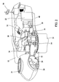
- control system provides control signals to a variable blade pitch drive 24 positioned within a cavity 25 formed by hub 20 (which includes a DC pitch drive motor, not shown in Figure 2) to control the pitch of blades 18 that drive hub 20 as a result of wind.
- hub 20 receives three blades 18, but other embodiments can utilize any number of blades.
- a pitch of each blade 18 is individually controlled by blade pitch drive 24.
- the drive train of wind turbine generator 10 includes a main rotor shaft 26 (also referred to as a "low speed shaft”) connected to hub 20 and a gear box 28 that, in some embodiments, utilizes a dual path geometry to drive a high speed shaft enclosed within gear box 28.
- the high speed shaft (not shown in Figure 2) is used to drive a first generator 30 that is supported by main frame 40.
- rotor torque is transmitted via coupling 32.
- First generator 30 may be of any suitable type including, without limitation, a wound rotor induction generator or a multi-pole generator that can run at the speed of the low speed shaft in a direct drive configuration, without requiring a gearbox.
- Yaw drive 34 and yaw deck 36 provide a yaw orientation system for wind turbine generator 10.
- the yaw orientation system is electrically operated and controlled by the control system in accordance with information received from sensors used to measure shaft flange displacement, for example.
- a wind vane 38 provides information for the yaw orientation system.
- the yaw orientation system is mounted on a flange provided atop tower 14.
- heat-sensitive electronic power components are mounted with respect to each blade 18.
- the power components are housed within a suitable enclosure 45, as shown in phantom lines in Figure 3.
- Enclosure 45 has suitable dimensions to fully enclose the electronic power components of wind turbine generator 10.
- a temperature within enclosure 45 is suitably less than about 150°C, and desirably less than about 125°C to prevent or minimize maintenance and material problems, component degradation and/or failure and ultimately turbine failure as a result of excessive heat within enclosure 45.
- At least one heat sink 50 is positioned within cavity 25 to dissipate thermal energy, including heat generated as a result of the wind turbine generator operation.
- heat generated within hub 20 during the production of electricity by wind turbine generator 10, as shown in Figure 1 is dissipated by at least one heat sink 50 mounted with respect to the heat generating components of wind turbine generator 10.
- wind turbine generator 10 includes heat sink 50, such as shown in Figures 3-6, attached with respect to each blade 18 to dissipate heat generated within enclosure 45.
- Heat sink 50 is attached to an outer surface of enclosure 45 to transfer heat from within enclosure 45 to heat sink 50 to maintain a temperature within enclosure 45 below a determined failure temperature.
- Figure 3 illustrates a perspective view of an exemplary heat sink 50 including a base 52 having a bottom surface 54 that attaches to the outer surface of enclosure 45 and an opposing top surface 56.
- bottom surface 54 and/or top surface 56 has a generally planar configuration.
- bottom surface 54 and/or top surface 56 has an arcuate configuration to correspond with a surface to which base 52 is mounted.
- a plurality of pins 58 extend from top surface 56 to dissipate thermal energy to cavity 25.
- pins 58 are positioned on top surface 56 to increase a surface area of heat sink 50 effective to dissipate thermal energy transferred to heat sink 50 from enclosure 45.
- pins 58 are positioned with respect to adjacent pins 58 so that air can flow across heat sink 50 in any direction. As a result of pin spacing, an air flow pattern is formed allowing air to flow between adjacent pins 58 in any suitable direction between about 0° and about 360° while maintaining a consistent, predictable thermal performance.
- each pin 58 has a generally tubular configuration and a height, width and/or diameter that is equal to adjacent pins 58.
- pin 58 is spaced with respect to adjacent pins 58, based on pin height, width and/or diameter, to form a desired air flow pattern.
- pin 58 has any suitable configuration, such as a cylindrical or conical configuration, with a suitable cross-sectional shape.
- heat sink 50 including pins 58 is fabricated using an injection casting process.
- Heat sink 50 and/or pins 58 are fabricated using any suitable material known to those skilled in the art and guided by the teachings herein provided that is fabricated using an injection casting process, and that provide the thermal energy transfer properties required for heat sink 50 and/or pins 58 described herein. Spacing between adjacent pins 58 is based on pin height, pin base diameter and/or pin configuration to provide efficient air flow through pins 58.
- base 52 is void of any pins 58.
- a fan 60 is mounted with respect to heat sink 50 and positioned in a spaced relationship with respect to pins 58 to provide for additional thermal dissipation, as desired.
- fan 60 is rotatably mounted on a fan shaft 62 extending from top surface 56.
- Fan shaft 62 defines a rotational axis 64 about which fan 60 rotates.
- Fan 60 includes any suitable number of fan blades 66.
- fan 60 includes five fan blades 66 radially positioned about rotational axis 64, but other embodiments can utilize any number of fan blades 66.
- Fan 60 is positioned such that a suitable distance between a bottom edge of each fan blade 66 and a top surface of each pin 58 is provided for efficient forced air flow between pins 58.
- a pitch of each fan blade 66 is adjustable to provide forced air cooling based on a rotational speed of wind turbine rotor 16, a rotational speed of fan 60 and/or the pitch of fan blades 66.
- fan 60 is mounted to top surface 56 that is void of pins 58.
- one blade 67 includes a weight 68.
- Weight 68 is connected or integrated with blade 67 to counter-weight fan 60.
- Weighted blade 67 urges fan 60 to rotate towards a surface of the earth as a result of gravity, as rotor 16 rotates about rotor shaft 26.
- counter-weighted fan 60 rotates with respect to top surface 56 of heat sink 50 to force air across top surface 56 and/or between pins 58.
- heat generated during wind turbine generator operation is transferred from within enclosure 45 into heat sink 50 and through pins 58. The heat is then transferred from heat sink 50 and/or pins 58 into cavity 25 as the forced air flows across heat sink 50 and/or between pins 58.
- heated air within a hub of a conventional wind turbine generator theoretically rotates with the hub and will not flow across a heat sink.
- Such state is referred to as "pooling" of heated air.
- Weighted fan 60 of the present invention counteracts this theoretical state and forces air across heat sink 50 and/or pins 58 to transfer thermal energy from heat sink 50 and/or pins 58 to the forced air and dissipate thermal energy within cavity 25.
- additional thermal performance is provided by at least one fan speed multiplier stage 70, as shown in Figure 5.
- Fan speed multiplier stage 70 is mounted with respect to top surface 56 and operatively coupled to fan shaft 62 to increase the rotational speed of fan 60, which in turn increases a volume and/or speed of the cooling air forced across heat sink 50 and/or between pins 58. The increased volume and/or speed of the cooling air provides additional thermal performance to heat sink 50.
- forced air cooling is provided based upon the rotational speed of wind turbine rotor 16, the rotational speed of fan 60, the pitch of fan blades 66, the number of fan speed multiplier stages 70 incorporated into the heat sink system and/or a pulley or gear ratio of each fan speed multiplier stage 70, as discussed below.
- fan speed multiplier stage 70 includes a first pulley 72 securely mounted to fan shaft 62.
- first pulley 72 is suitably weighted to urge fan 60 to rotate about rotational axis 64 as rotor 16 rotates about rotor shaft 26.
- first pulley 72 includes a weighted section 73.
- a second pulley 74 is rotatably mounted to top surface 56 and operatively connected to first pulley 72.
- second pulley 74 is rotatably mounted to a shaft 76, which is securely mounted to base 52.
- a belt 78 couples first pulley 72 to a hub 80 formed on second pulley 74.
- a belt 82 couples second pulley 74 to a hub formed on first pulley 72 (not shown in Figure 5). Any suitable coupler known to those skilled in the art and guided by the teachings herein provided can be used to operatively couple first pulley 72 to second pulley 74.
- a circumference of first pulley 72 and/or a circumference of hub 80 are adjustable to provide a pulley ratio, as desired.
- a circumference of second pulley 74 and/or a circumference of the first pulley hub are adjustable to provide a desired pulley ratio.
- the pulley ratio e.g., the circumference of first pulley 72 to the circumference of hub 80 and the circumference of second pulley 74 to the circumference of the first pulley hub, is 8:1.
- the 8:1 pulley ratio results in a rotational speed of fan 60 of about 120 rpm in relation to a rotational speed of rotor 16 of about 20 rpm.
- a second fan speed multiplier stage (not shown in Figure 5) is operatively coupled to fan speed multiplier stage 70 using a suitable coupler, such as discussed above in reference to fan speed multiplier stage 70.
- second pulley 74 includes a gear (not shown in Figure 5) that interlocks with a gear formed on weighted pulley 72 (not shown in Figure 5) and operatively connects second pulley 74 to weighted pulley 72.
- a circumference of the second pulley gear and/or a circumference of the weighted pulley gear is adjustable to provide a gear ratio, as desired.
- the heat sink system of the present invention includes a frame 90 at least partially covering heat sink 50 and top surface 56, as shown in Figure 6.
- Frame 90 is fabricated from a suitable sheet metal material and provides support for fan shaft 62 and/or shaft 76.
- Frame 90 attaches to enclosure 45, shown in phantom lines in Figure 6, and protects the components of the heat sink system from undesirable contact and/or damage.
- a method for dissipating thermal energy to a cavity formed within a wind turbine generator hub includes positioning heat sink 50 on a surface of enclosure 45 that is positioned within cavity 25.
- one heat sink 50 is positioned on each of three enclosures 45 at least partially positioned within cavity 25 and extending along a corresponding rotor blade 18.
- Fan 60 is rotatably mounted to top surface 56 of heat sink 50 and includes a plurality of fan blades 66 positioned radially about fan shaft 62. Fan 60 is urged to rotate with respect to top surface 56 as rotor 16 rotates about rotor shaft 26. A flow of air is forced by the rotation of fan 60 across top surface 56 to dissipate the thermal energy from heat sink 50.
- fan 60 includes one weighted blade 67 that urges fan 60 to rotate with respect to top surface 56 in response to a gravity force pulling weighted blade 67 towards the earth, as rotor 16 rotates about rotor shaft 26.
- the forced air flows between pins 58 extending from top surface 56 and forming an air flow path therebetween.
- a rotational speed of fan 60 with respect to top surface 56 is increased, as desired, to increase the flow of air across top surface 56 and/or between pins 58.
- fan speed multiplier stage 70 provides additional torque on fan shaft 62 to rotate fan 60 about fan shaft 62 at an increased rotational speed.
- the above-described method and apparatus of the present invention provide predictable and consistent wind turbine generator thermal performance. More specifically, the method and apparatus efficiently dissipates thermal energy generated within a rotor hub by positioning at least one heat sink with respect to a heat generating component of the wind turbine generator to transfer thermal energy from the heat generating component to a cavity formed within the hub.
- the heat sink allows for variations in air flow direction with the use of pins extending from a top surface of the heat sink, while maintaining predictable and consistent thermal performance.
- Exemplary embodiments of a method, an apparatus and a system for dissipating thermal energy generated by an operating component are described above in detail.
- the method, apparatus and system are not limited to the specific embodiments described herein, but rather, steps of the method and/or elements or components of the apparatus and system may be utilized independently and separately from others described herein. Further, the described method steps and/or apparatus and system elements or components can also be defined in, or used in combination with, other methods, apparatus and/or systems and are not limited to practice only as described herein.
- wind turbine generator 10 wind turbine generator 12 nacelle 14 tower 16 wind turbine rotor 18 blades 20 hub 22 control panel 24 blade pitch drive 25 cavity 26 rotor shaft 28 gear box 30 first generator 32 coupling 34 yaw drive 36 yaw deck 38 wind vane 40 main frame 45 enclosure 50 heat sink 52 base 54 bottom surface 56 top surface 58 pins 60 fan 62 fan shaft 64 rotational axis 66 fan blades 67 weighted blade 68 weight 70 fan speed multiplier stages 72 first pulley 73 weighted section 74 second pulley 76 shaft 78 belt 80 hub 82 belt 90 frame
Landscapes
- Engineering & Computer Science (AREA)
- Microelectronics & Electronic Packaging (AREA)
- Physics & Mathematics (AREA)
- Thermal Sciences (AREA)
- Life Sciences & Earth Sciences (AREA)
- Sustainable Development (AREA)
- Sustainable Energy (AREA)
- Chemical & Material Sciences (AREA)
- Combustion & Propulsion (AREA)
- Mechanical Engineering (AREA)
- General Engineering & Computer Science (AREA)
- Wind Motors (AREA)
Applications Claiming Priority (1)
| Application Number | Priority Date | Filing Date | Title |
|---|---|---|---|
| US11/249,869 US7235895B2 (en) | 2005-10-13 | 2005-10-13 | Method and apparatus for gravity induced thermal energy dissipation |
Publications (2)
| Publication Number | Publication Date |
|---|---|
| EP1783367A2 true EP1783367A2 (de) | 2007-05-09 |
| EP1783367A3 EP1783367A3 (de) | 2012-11-14 |
Family
ID=37192627
Family Applications (1)
| Application Number | Title | Priority Date | Filing Date |
|---|---|---|---|
| EP06255200A Withdrawn EP1783367A3 (de) | 2005-10-13 | 2006-10-09 | Verfahren und Vorrichtung zur Umwandlung von Schwerkraftinduziertewärmeenergie |
Country Status (6)
| Country | Link |
|---|---|
| US (1) | US7235895B2 (de) |
| EP (1) | EP1783367A3 (de) |
| CN (1) | CN1966972B (de) |
| AU (1) | AU2006222703B2 (de) |
| BR (1) | BRPI0604663A (de) |
| CA (1) | CA2561306C (de) |
Cited By (1)
| Publication number | Priority date | Publication date | Assignee | Title |
|---|---|---|---|---|
| CN112492817A (zh) * | 2020-12-17 | 2021-03-12 | 河南工业职业技术学院 | 一种经济管理数据分析装置 |
Families Citing this family (9)
| Publication number | Priority date | Publication date | Assignee | Title |
|---|---|---|---|---|
| CN102705162B (zh) * | 2003-08-12 | 2014-10-22 | 纳博特斯克株式会社 | 风力发电机的偏摆驱动装置 |
| ES2330491B1 (es) * | 2007-05-25 | 2010-09-14 | GAMESA INNOVATION & TECHNOLOGY, S.L. | Sistema de climatizacion para aerogeneradores. |
| US20090094981A1 (en) * | 2007-10-12 | 2009-04-16 | General Electric Company | Wind turbine geothermal heating and cooling system |
| JP2009250214A (ja) * | 2008-04-10 | 2009-10-29 | Mitsubishi Heavy Ind Ltd | 風力発電装置用ファン装置および風力発電装置 |
| JP5148517B2 (ja) | 2009-01-07 | 2013-02-20 | 三菱重工業株式会社 | 風力発電装置 |
| US10137542B2 (en) | 2010-01-14 | 2018-11-27 | Senvion Gmbh | Wind turbine rotor blade components and machine for making same |
| MX341495B (es) | 2010-01-14 | 2016-08-23 | Neptco Inc * | Componentes de pala de rotor de turbina eolica y metodos para la fabricacion de los mismos. |
| CN112302889B (zh) * | 2020-10-15 | 2021-08-17 | 江苏万顺新能源科技有限公司 | 一种风力发电机滤盒结构 |
| CN117595563B (zh) * | 2024-01-18 | 2024-04-02 | 湖南创一智能科技有限公司 | 一种电机空空冷却器 |
Family Cites Families (13)
| Publication number | Priority date | Publication date | Assignee | Title |
|---|---|---|---|---|
| JPS586977A (ja) * | 1981-07-03 | 1983-01-14 | Sumitomo Metal Ind Ltd | 着色鋼板の製造方法 |
| GB2276763B (en) * | 1993-03-30 | 1997-05-07 | Thermalloy Inc | Method and apparatus for dissipating thermal energy |
| GB2312324B (en) * | 1996-04-19 | 2000-11-15 | Hong Chen Fu In | Fan/pins seat assembly for an integrated circuit |
| DE19636591C2 (de) * | 1996-09-10 | 1999-12-09 | Friedrich Klinger | Synchrongenerator für einen getriebelosen Windenergiekonverter |
| US6439850B1 (en) | 1998-07-15 | 2002-08-27 | Flexxaire Manufacturing Inc. | Variable pitch fan |
| CA2243151C (en) | 1998-07-15 | 2008-06-17 | Flexxaire Manufacturing Inc. | Variable pitch fan |
| EP1185790B1 (de) | 1999-05-07 | 2004-10-27 | NEG Micon A/S | Offshore windturbine mit flüssigkeitskühlung |
| US6483199B2 (en) * | 2000-04-28 | 2002-11-19 | Mitsubishi Denki Kabushiki Kaisha | Wind power generating device |
| DE10124268B4 (de) * | 2001-05-18 | 2006-02-09 | Wobben, Aloys, Dipl.-Ing. | Generatorkühlung |
| US20030067228A1 (en) | 2001-10-09 | 2003-04-10 | Vanjani Chandu R. | Heat dissipative brushless electric motor assembly |
| DE202004020094U1 (de) * | 2004-03-22 | 2005-03-10 | Siemens Ag | Ventilatorummantelung, Ventilator mit einer Ventilatorummantelung und Windenergieanlage mit einem Ventilator |
| US20060011336A1 (en) | 2004-04-07 | 2006-01-19 | Viktor Frul | Thermal management system and computer arrangement |
| US7345376B2 (en) * | 2004-11-30 | 2008-03-18 | Distributed Energy Systems Corporation | Passively cooled direct drive wind turbine |
-
2005
- 2005-10-13 US US11/249,869 patent/US7235895B2/en not_active Expired - Fee Related
-
2006
- 2006-09-27 AU AU2006222703A patent/AU2006222703B2/en not_active Ceased
- 2006-09-28 CA CA2561306A patent/CA2561306C/en not_active Expired - Fee Related
- 2006-10-09 EP EP06255200A patent/EP1783367A3/de not_active Withdrawn
- 2006-10-11 BR BRPI0604663-0A patent/BRPI0604663A/pt not_active IP Right Cessation
- 2006-10-13 CN CN2006101647226A patent/CN1966972B/zh not_active Expired - Fee Related
Cited By (1)
| Publication number | Priority date | Publication date | Assignee | Title |
|---|---|---|---|---|
| CN112492817A (zh) * | 2020-12-17 | 2021-03-12 | 河南工业职业技术学院 | 一种经济管理数据分析装置 |
Also Published As
| Publication number | Publication date |
|---|---|
| EP1783367A3 (de) | 2012-11-14 |
| BRPI0604663A (pt) | 2007-08-28 |
| CA2561306C (en) | 2015-09-08 |
| CN1966972B (zh) | 2011-08-10 |
| AU2006222703A1 (en) | 2007-05-03 |
| CA2561306A1 (en) | 2007-04-13 |
| CN1966972A (zh) | 2007-05-23 |
| US20070085346A1 (en) | 2007-04-19 |
| US7235895B2 (en) | 2007-06-26 |
| AU2006222703B2 (en) | 2011-12-01 |
Similar Documents
| Publication | Publication Date | Title |
|---|---|---|
| US7750490B2 (en) | Method and system for extracting inertial energy from a wind turbine | |
| US8093737B2 (en) | Method for increasing energy capture in a wind turbine | |
| US8035241B2 (en) | Wind turbine, control system, and method for optimizing wind turbine power production | |
| US8013460B2 (en) | Method and apparatus for controlling noise levels of a turbine with minimal loss in energy yield | |
| US7352075B2 (en) | Methods and apparatus for controlling rotational speed of a rotor | |
| EP2273105B1 (de) | Verfahren und Vorrichtung zur geräuschoptimierten Steuerung einer Windkraftanlage | |
| US7397143B2 (en) | Methods and apparatus for supplying and/or absorbing reactive power | |
| CN101520026B (zh) | 风力涡轮机站强风降级控制 | |
| JP2004251270A (ja) | 高エネルギー収量をもつ風力発電装置 | |
| CN105201742A (zh) | 控制风力发电设备的系统和方法 | |
| WO2005103489A2 (en) | Direct drive wind turbine | |
| KR20050116909A (ko) | 탠덤형 두 개의 로터를 구비한 풍력 발전 장치 | |
| US7235895B2 (en) | Method and apparatus for gravity induced thermal energy dissipation | |
| EP2439408A2 (de) | System und Verfahren zum Verteilen von Luft in einer Windturbine | |
| CN201515291U (zh) | 一种直驱式风力发电机 | |
| EP4125191B1 (de) | Kühlung von aktiven elementen von elektrischen maschinen | |
| WO2012114891A1 (ja) | 風力発電装置 | |
| Karimirad | Wind turbines | |
| KR20230016582A (ko) | 전기 기계의 능동 요소들의 냉각 | |
| HK1130527A (en) | Direct drive wind turbine |
Legal Events
| Date | Code | Title | Description |
|---|---|---|---|
| PUAI | Public reference made under article 153(3) epc to a published international application that has entered the european phase |
Free format text: ORIGINAL CODE: 0009012 |
|
| AK | Designated contracting states |
Kind code of ref document: A2 Designated state(s): AT BE BG CH CY CZ DE DK EE ES FI FR GB GR HU IE IS IT LI LT LU LV MC NL PL PT RO SE SI SK TR |
|
| AX | Request for extension of the european patent |
Extension state: AL BA HR MK YU |
|
| RIN1 | Information on inventor provided before grant (corrected) |
Inventor name: LINDHOLM, BRIAN ERIC Inventor name: EDMUNDS, HOWARD ROSS Inventor name: MCMENAMIN, CHRISTOPHER Inventor name: RIDENOUR, AMY MARLENE Inventor name: BONNEAU, WILLIAM JOHN Inventor name: MELIUS, JEFFREY ALAN Inventor name: WILKINSON, ANDREW SCOTT Inventor name: MOORE, CHRISTOPHER TODD Inventor name: HARBOURT, CYRUS DAVID Inventor name: AIKEN, BRIAN MATTHEW |
|
| RIN1 | Information on inventor provided before grant (corrected) |
Inventor name: RIDENOUR, AMY MARLENE Inventor name: MCMENAMIN, CHRISTOPHER Inventor name: AIKEN, BRIAN MATTHEW Inventor name: MOORE, CHRISTOPHER TODD Inventor name: MELIUS, JEFFREY ALAN Inventor name: BONNEAU, WILLIAM JOHN Inventor name: HARBOURT, CYRUS DAVID Inventor name: EDMUNDS, HOWARD ROSS Inventor name: LINDHOLM, BRIAN ERIC Inventor name: WILKINSON, ANDREW SCOTT |
|
| PUAL | Search report despatched |
Free format text: ORIGINAL CODE: 0009013 |
|
| AK | Designated contracting states |
Kind code of ref document: A3 Designated state(s): AT BE BG CH CY CZ DE DK EE ES FI FR GB GR HU IE IS IT LI LT LU LV MC NL PL PT RO SE SI SK TR |
|
| AX | Request for extension of the european patent |
Extension state: AL BA HR MK RS |
|
| RIC1 | Information provided on ipc code assigned before grant |
Ipc: H05K 7/20 20060101ALI20121011BHEP Ipc: F03G 3/00 20060101ALI20121011BHEP Ipc: F03D 11/00 20060101AFI20121011BHEP |
|
| 17P | Request for examination filed |
Effective date: 20130514 |
|
| AKX | Designation fees paid |
Designated state(s): AT BE BG CH CY CZ DE DK EE ES FI FR GB GR HU IE IS IT LI LT LU LV MC NL PL PT RO SE SI SK TR |
|
| GRAP | Despatch of communication of intention to grant a patent |
Free format text: ORIGINAL CODE: EPIDOSNIGR1 |
|
| RIC1 | Information provided on ipc code assigned before grant |
Ipc: F03D 80/00 20160101AFI20160817BHEP Ipc: H05K 7/20 20060101ALI20160817BHEP Ipc: F03G 3/00 20060101ALI20160817BHEP |
|
| INTG | Intention to grant announced |
Effective date: 20160909 |
|
| STAA | Information on the status of an ep patent application or granted ep patent |
Free format text: STATUS: THE APPLICATION IS DEEMED TO BE WITHDRAWN |
|
| 18D | Application deemed to be withdrawn |
Effective date: 20170120 |