EP1783258A1 - Embroidery module for a free arm sewing machine - Google Patents
Embroidery module for a free arm sewing machine Download PDFInfo
- Publication number
- EP1783258A1 EP1783258A1 EP06405387A EP06405387A EP1783258A1 EP 1783258 A1 EP1783258 A1 EP 1783258A1 EP 06405387 A EP06405387 A EP 06405387A EP 06405387 A EP06405387 A EP 06405387A EP 1783258 A1 EP1783258 A1 EP 1783258A1
- Authority
- EP
- European Patent Office
- Prior art keywords
- embroidery
- module
- embroidery module
- sewing machine
- free arm
- Prior art date
- Legal status (The legal status is an assumption and is not a legal conclusion. Google has not performed a legal analysis and makes no representation as to the accuracy of the status listed.)
- Granted
Links
Images


Classifications
-
- D—TEXTILES; PAPER
- D05—SEWING; EMBROIDERING; TUFTING
- D05B—SEWING
- D05B21/00—Sewing machines with devices for automatically controlling movement of work-carrier relative to stitch-forming mechanism in order to obtain particular configuration of seam, e.g. programme-controlled for sewing collars, for attaching pockets
-
- D—TEXTILES; PAPER
- D05—SEWING; EMBROIDERING; TUFTING
- D05C—EMBROIDERING; TUFTING
- D05C9/00—Appliances for holding or feeding the base fabric in embroidering machines
- D05C9/02—Appliances for holding or feeding the base fabric in embroidering machines in machines with vertical needles
- D05C9/04—Work holders, e.g. frames
Definitions
- the invention relates to an embroidery module for a free-arm sewing machine according to the preamble of patent claim 1.
- Free-arm sewing machines for home use have a relatively small work surface to edit even tubular workpieces such as sleeves can.
- extension tables are often supplied with the sewing machine, which have a U-shaped form and enclose the free arm on three sides.
- this much larger work and support surface prevents sewing or embroidery of tubular material.
- an embroidery module which serves the drive and the support of an embroidery frame, the work surface for large workpieces can be extended.
- a disadvantage is that in each case depending on the work to be done the Anschiebetisch or the embroidery module must be removed again to perform another job on the sewing machine can.
- An object of the present invention is to provide an embroidery module, which serves both its main purpose, namely the drive and guiding an embroidery frame, but also permanently as an enlarged work surface can be used without thereby the possibilities of Freiarm proceedingsns or Freiarmstickens tubular workpieces docked Embroidery module must be restricted.
- the advantage here is not only the use of the embroidery module as an extended work surface thanks to the completely removable from the embroidery module embroidery frame carrier, but also that for larger embroidery hoop and according to the large edge length of such embroidery hoop thus long embroidery frame carrier can be stored separately from the embroidery module.
- the embroidery module without embroidery frame carrier always remain coupled to the sewing machine or it is advantageous to keep it docked to the machine.
- the embroidery module can also remain docked.
- the latter can be removed from the machine if only tubular workpieces are processed for a long time.
- the storage of the embroidery frame carrier in guides which are located laterally of the embroidery module prevents dust or sewing utensils, e.g. Needles or thread sections, can get into the guide rails.
- the slot-free surface of the embroidery module thereby forms a closed fabric support which does not interfere with the material movement during sewing and embroidering.
- the embroidery module 1 shown in FIGS. 1 and 2 comprises a main body 3 of substantially rectangular ground plan. On one of the two narrow sides of a recess 5 is visible, which may be open at the bottom or, as in the illustrated embodiment, an approximately v-shaped or cylinder jacket-shaped bottom 7 has. Below the bottom 7 may be mounted over the entire base body 3 extending bottom plate 9.
- slits 11 are formed parallel to its upper surface, which extend on the side of the narrow-side recess 5 to or only approximately to the end face of the embroidery module 1; on the opposite narrow side, however, are open.
- drive means such as toothed belts, round belts, metal bands, strands or spindles are used, which can convey an embroidery frame carrier 13 guided exactly parallel in the X direction via suitable coupling means.
- the connection of the embroidery frame carrier 13 with the transport means located behind the slots 11 takes place via lugs 15 (see FIG. 2), which pass through the slots 11 into the not-described and not visible one Intervene coupling agent.
- the tabs 15 are dimensioned such that there is a gap between the elongated housing 17 of the embroidery frame carrier 13 and the work surface 19 on the embroidery module 1. That is, the embroidery frame carrier 13 or the embroidery frame 25 does not touch the surface of the embroidery module 1.
- a second drive motor for an embroidery frame adapter 21 is present in the central, in the figures 1/2, cylindrical section 20, which is movably mounted in the Y-direction in the embroidery frame carrier 13.
- the embroidery frame adapter 21 may, for example, have holes 23 to which an embroidery frame 25 can be attached (compare FIGS. 5 and 6).
- the embroidery module 1 in combination with a household sewing machine 27, ie, docked to such, described in more detail. It can be seen in FIGS. 3 a to 3 c that the embroidery module 1 is fastened to the end face of the base plate 29 of the sewing machine 27 along the edge Q and that the free arm 31 protrudes into the recess 5 on the embroidery module 1 only by a small amount a.
- the rest of the area of the recess 5 in the embroidery module 1 is not filled by a part of the sewing machine 27, but serves as a free space 33 for insertion, for example, a tubular Sewing material on the free arm 31.
- the embroidery module 1 is used solely as an enlarged work surface, ie as a bed rest, especially when sewing gossflambaiger workpieces.
- a Anschiebetisch 35 which can be docked without embroidery module 1 on the free arm 31 of the sewing machine, can be attached.
- the free space 33 formed by the recess 5, closed at the top and on the other hand in front of and behind the free arm 31 (seen in sewing direction), the support surface on the sewing machine additionally widened (see Figures 4a to 4c). It is of course not possible in this arrangement, the processing of tubular workpieces.
- the embroidery frame carrier 13 is placed on the embroidery module 1. This is supported by the two tabs 15, which engage in the lateral slots 11 on the main body 3 of the embroidery module 1.
- On the embroidery frame carrier 13 of the embroidery frame 25 is fixed, with which a clamped held therein fabric 37 by a computer-aided program under the needle (not shown) of the sewing machine 27 is mounted movable in the x and y directions.
- the embroidery frame 25 rests on the extension table 35, as shown in FIGS. 4a to 4c. In the illustration according to FIGS. 6 a to 6 c, the embroidery frame 25 lies directly on the surface of the free arm 31.
- the space 33 formed by the recess 5 is not closed at the top and the free arm 31 itself is laterally exposed. It can therefore in the hoop 25 also tubular workpieces or hemispherical, such as caps, be clamped. The unrestrained part of these sewing materials can thus move around the free arm 31 undisturbed during sewing or embroidering.
- the inventive embroidery module 1 In none of the four examples of use of the inventive embroidery module 1, the latter must be removed from the sewing machine 27. All work carried out on a sewing machine 27 can consequently also be carried out when the embroidery module 1 is docked remains. For many sewing jobs in which the embroidery module 1 is not needed per se, but this favors, when docked, sewing, quilting or embroidery.
- the embroidery frame carrier 13, which is not required when working without embroidery frame 25, can be easily removed without tools from the embroidery module 1 and placed aside.
Abstract
Description
Gegenstand der Erfindung ist ein Stickmodul für eine Freiarm-Nähmaschine gemäss Oberbegriff des Patentanspruchs 1.The invention relates to an embroidery module for a free-arm sewing machine according to the preamble of
Freiarm-Nähmaschinen für den Heimgebrauch weisen eine verhältnismässig kleine Arbeitsfläche auf, um auch rohrförmige Werkstücke wie Ärmel etc. bearbeiten zu können. Zur besseren Abstützung von grösseren Werkstücken werden häufig mit der Nähmaschine sogenannte Anschiebetische mitgeliefert, welche eine u-förmige Gestalt aufweisen und den Freiarm dreiseitig umschliessen. Diese wesentlich grössere Arbeits- und Abstützfläche verhindert jedoch das Nähen oder Besticken von rohrförmigem Nähgut.
Auch durch das Andocken eines Stickmoduls, welches dem Antrieb und der Auflage eines Stickrahmens dient, kann die Arbeitsfläche für grosse Werkstücke erweitert werden. Nachteilig ist dabei, dass jeweils je nach zu verrichtender Arbeit der Anschiebetisch oder das Stickmodul wieder abgenommen werden müssen, um eine andere Arbeit auf der Nähmaschine durchführen zu können.Free-arm sewing machines for home use have a relatively small work surface to edit even tubular workpieces such as sleeves can. For better support of larger workpieces so-called extension tables are often supplied with the sewing machine, which have a U-shaped form and enclose the free arm on three sides. However, this much larger work and support surface prevents sewing or embroidery of tubular material.
Also, by docking an embroidery module, which serves the drive and the support of an embroidery frame, the work surface for large workpieces can be extended. A disadvantage is that in each case depending on the work to be done the Anschiebetisch or the embroidery module must be removed again to perform another job on the sewing machine can.
Eine Aufgabe der vorliegenden Erfindung ist die Schaffung eines Stickmoduls, das sowohl seinem Hauptzweck, nämlich dem Antrieb und dem Führen eines Stickrahmens dient, zudem aber dauernd auch als vergrösserte Arbeitsfläche eingesetzt werden kann, ohne dass dabei die Möglichkeiten des Freiarmnähens oder Freiarmstickens rohrförmiger Werkstücke bei angedocktem Stickmodul eingeschränkt werden müssen.An object of the present invention is to provide an embroidery module, which serves both its main purpose, namely the drive and guiding an embroidery frame, but also permanently as an enlarged work surface can be used without thereby the possibilities of Freiarmnähens or Freiarmstickens tubular workpieces docked Embroidery module must be restricted.
Gelöst wird diese Aufgabe durch die Merkmale des Patentanspruchs 1. Vorteilhafte Ausgestaltungen der Erfindung sind in den abhängigen Ansprüchen umschrieben.This object is achieved by the features of
Es gelingt durch die Ausgestaltung des erfindungsgemässen Stickmoduls, diese Aufgabe in verschiedener Hinsicht einwandfrei zu lösen. Vorteilhaft dabei ist nicht nur die Verwendung des Stickmoduls als erweiterte Arbeitsfläche dank dem vollständig vom Stickmodul abnehmbaren Stickrahmenträger, sondern auch, dass ein für grössere Stickrahmen und entsprechend der grossen Kantenlänge solcher Stickrahmen folglich lange Stickrahmenträger separat vom Stickmodul aufbewahrt werden kann. Für die meisten anfallenden Näharbeiten kann das Stickmodul ohne Stickrahmenträger stets an der Nähmaschine angekuppelt bleiben bzw. es ist vorteilhaft, dieses an der Maschine angedockt zu halten. Für einzelne Anwendungen, bei denen die Eigenschaften des Freiarms benötigt werden, kann das Stickmodul ebenfalls angedockt bleiben.It is possible by the design of the embroidery module according to the invention to solve this problem properly in various respects. The advantage here is not only the use of the embroidery module as an extended work surface thanks to the completely removable from the embroidery module embroidery frame carrier, but also that for larger embroidery hoop and according to the large edge length of such embroidery hoop thus long embroidery frame carrier can be stored separately from the embroidery module. For most of the sewing work, the embroidery module without embroidery frame carrier always remain coupled to the sewing machine or it is advantageous to keep it docked to the machine. For individual applications in which the characteristics of the free arm are needed, the embroidery module can also remain docked.
Andererseits kann letzteres, im Gegensatz zu fest mit der Maschine verbundenen Stickrahmenantrieben, von der Maschine abgenommen werden, wenn über längere Zeit ausschliesslich rohrförmige Werkstücke verarbeitet werden. Die Lagerung des Stickrahmenträgers in Führungen, die sich seitlich des Stickmoduls befinden, verhindert, dass Staub oder Nähutensilien, z.B. Nadeln oder Fadenabschnitte, in die Führungsschienen gelangen können. Ausserdem bildet die schlitzfreie Oberfläche des Stickmoduls dadurch eine geschlossene, die Stoffbewegung beim Nähen und Sticken nicht störende Stoffauflage.On the other hand, in contrast to embroidery frame drives permanently connected to the machine, the latter can be removed from the machine if only tubular workpieces are processed for a long time. The storage of the embroidery frame carrier in guides which are located laterally of the embroidery module prevents dust or sewing utensils, e.g. Needles or thread sections, can get into the guide rails. In addition, the slot-free surface of the embroidery module thereby forms a closed fabric support which does not interfere with the material movement during sewing and embroidering.
Anhand eines illustrierten Ausführungsbeispiels wird die Erfindung näher erläutert. Es zeigen:
Figur 1- eine perspektivische Darstellung eines Stickmoduls mit abgenommenem Stickrahmenträger,
- Figur 2
- eine perspektivische Untersicht eines Stickmoduls mit abgenommenem Stickrahmenträger,
- Figur 3a
- eine perspektivische Darstellung einer Nähmaschine mit angedocktem Stickmodul,
- Figur 3b
- eine Seitenansicht der Nähmaschine mit angedocktem Stickmodul,
- Figur 3c
- eine Aufsicht auf eine Nähmaschine mit angedocktem Stickmodul,
- Figur 4a
- eine perspektivische Darstellung der Nähmaschine mit angedocktem Stickmodul und aufgesetztem Anschiebetisch,
- Figur 4b
- eine Seitenansicht der Nähmaschine mit aufgesetztem Anschiebetisch,
- Figur 4c
- eine Aufsicht auf eine Nähmaschine mit aufgesetztem Anschiebetisch,
- Figur 5a
- eine perspektivische Darstellung der Nähmaschine und des Stickmoduls mit aufgesetztem Stickrahmenträger sowie dem Stickrahmen und dem Anschiebetisch,
- Figur 5b
- eine Seitenansicht der Nähmaschine und des Stickmoduls mit aufgesetztem Stickrahmenträger sowie Stickrahmen mit Anschiebetisch,
- Figur 5c
- eine Aufsicht auf eine Nähmaschine und das Stickmodul mit aufgesetztem Stickrahmenträger sowie Stickrahmen mit Anschiebetisch,
- Figur 6a
- eine perspektivische Darstellung der Nähmaschine, des Stickmoduls und aufgesetztem Stickrahmenträger ohne Anschiebetisch,
- Figur 6b
- eine Seitenansicht der Nähmaschine, des Stickmoduls und aufgesetztem Stickrahmenträger ohne Anschiebetisch,
- Figur 6c
- eine Aufsicht auf eine Nähmaschine und das Stickmodul mit aufgesetztem Stickrahmenträger ohne Anschiebetisch.
- FIG. 1
- a perspective view of an embroidery module with removed embroidery frame carrier,
- FIG. 2
- a perspective bottom view of an embroidery module with removed embroidery frame carrier,
- FIG. 3a
- a perspective view of a sewing machine with docked embroidery module,
- FIG. 3b
- a side view of the sewing machine with docked embroidery module,
- Figure 3c
- a view of a sewing machine with docked embroidery module,
- FIG. 4a
- a perspective view of the sewing machine with docked embroidery module and attached Anschiebetisch,
- FIG. 4b
- a side view of the sewing machine with attached Anschiebetisch,
- Figure 4c
- a view of a sewing machine with attached Anschiebetisch,
- FIG. 5a
- a perspective view of the sewing machine and the embroidery module with attached embroidery frame carrier and the hoop and the Anschiebetisch,
- FIG. 5b
- a side view of the sewing machine and the embroidery module with attached embroidery frame carrier and embroidery hoop with Anschiebetisch,
- FIG. 5c
- a view of a sewing machine and the embroidery module with attached embroidery frame carrier and embroidery frame with Anschiebetisch,
- FIG. 6a
- a perspective view of the sewing machine, the embroidery module and attached embroidery frame carrier without Anschiebetisch,
- FIG. 6b
- a side view of the sewing machine, the embroidery module and attached embroidery frame carrier without Anschiebetisch,
- FIG. 6c
- a view of a sewing machine and the embroidery module with attached embroidery frame carrier without Anschiebetisch.
Das in den Figuren 1 und 2 dargestellte Stickmodul 1 umfasst einen Grundkörper 3 von im wesentlichem rechteckigem Grundriss. Auf einer der beiden Schmalseiten ist eine Ausnehmung 5 sichtbar, die nach unten offen sein kann oder, wie in der dargestellten Ausführung, einen etwa v-förmigen oder zylindermantelförmigen Boden 7 aufweist. Unterhalb des Bodens 7 kann eine sich über den gesamten Grundkörper 3 erstreckende Bodenplatte 9 angebracht sein. In den beiden längeren Seitenflächen 8,10 des Stickmoduls 1 sind parallel zu dessen oben liegender Fläche Schlitze 11 ausgebildet, welche sich auf der Seite der schmalseitigen Ausnehmung 5 bis zur oder nur annähernd bis zur Stirnseite des Stickmoduls 1 erstrecken; auf der gegenüberliegenden Schmalseite hingegen offen sind. Innerhalb des Stickmoduls 1 sind Antriebsmittel, wie Zahnriemen, Rundriemen, Metallbänder, Litzen oder Spindeln eingesetzt, welche über geeignete Kupplungsmittel einen Stickrahmenträger 13 exakt parallel geführt in X-Richtung transportieren können. Der Antrieb der Antriebsmittel für den Stickrahmenträger 13, die in den Figuren nicht dargestellt sind, da nicht sichtbar, erfolgt über mindestens einen ersten Elektromotor, der innerhalb des Stickmoduls 1 eingesetzt ist. Die Verbindung des Stickrahmenträgers 13 mit den hinter den Schlitzen 11 befindlichen Transportmitteln erfolgt über Laschen 15 (vgl. Figur 2), welche durch die Schlitze 11 hindurch in die nicht beschriebenen und nicht sichtbaren Kupplungsmittel eingreifen. Die Laschen 15 sind derart dimensioniert, dass zwischen dem langgestreckten Gehäuse 17 des Stickrahmenträgers 13 und der Arbeitsfläche 19 am Stickmodul 1 ein Zwischenraum vorliegt. D.h. der Stickrahmenträger 13 bzw. der Stickrahmen 25 berührt die Oberfläche des Stickmoduls 1 nicht.The
Im Gehäuse 17 des Stickrahmenträgers 13 ist im zentralen, in den Figuren 1/2, zylindrischen Abschnitt 20 ein zweiter Antriebsmotor für einen Stickrahmenadapter 21 vorhanden, welcher in Y-Richtung im Stickrahmenträger 13 verfahrbar gelagert ist. Der Stickrahmenadapter 21 kann beispielsweise Bohrungen 23 aufweisen, an denen ein Stickrahmen 25 befestigt werden kann (vgl. Figuren 5 und 6).In the
Nachfolgend wird das Stickmodul 1 in Kombination mit einer Haushalt-Nähmaschine 27, d.h. an einer solchen angedockt, näher beschrieben.
In den Figuren 3a bis 3c ist ersichtlich, dass das Stickmodul 1 längs Kante Q stirnseitig an der Stirnfläche der Grundplatte 29 der Nähmaschine 27 befestigt ist und dass der Freiarm 31 nur um einen geringen Betrag a in die Ausnehmung 5 am Stickmodul 1 hineinragt. Der übrige Bereich der Ausnehmung 5 im Stickmodul 1 wird nicht von einem Teil der Nähmaschine 27 ausgefüllt, sondern dient als Freiraum 33 zum Einschieben z.B. eines rohrförmigen Nähguts über den Freiarm 31. In der nun beschriebenen Anordnung (Figuren 3 und 4) dient das Stickmodul 1 einzig als vergrösserte Arbeitsfläche, d.h. als Nägutauflage insbesondere beim Nähen gossflächiger Werkstücke. Um die Nähgutauflage weiter zu erweitern, kann ein Anschiebetisch 35, welcher auch ohne Stickmodul 1 am Freiarm 31 der Nähmaschine andockbar ist, angebracht werden. Dadurch wird einerseits der Freiraum 33, gebildet durch die Ausnehmung 5, oben geschlossen und andererseits vor und hinter dem Freiarm 31 (in Nährichtung gesehen) die Auflagefläche an der Nähmaschine zusätzlich verbreitert (vgl. Figuren 4a bis 4c). Nicht möglich ist bei dieser Anordnung selbstverständlich das Bearbeiten von rohrförmigen Werkstücken. Dazu muss, wie in Figuren 3a bis 3c dargestellt, der Anschiebetisch 35 entfernt werden.
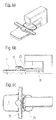
Damit der Anschiebetisch 35 bei angedocktem Stickmodul mit der Oberfläche des Freiarms 31 eine Ebene bildet, liegt die Oberfläche des Stickmoduls 1 auf der Höhe h2, d.h. um die Dicke d des Anschiebetisches (35) versetzt, tiefer als die Oberfläche des Freiarms 31, welche auf der Höhe h1 liegt (h1 - h2 = d). Diese Höhendifferenz zwischen der Oberfläche des Freiarms 31 und derjenigen des Stickmoduls 1 stört beim Nähen oder Sticken ohne Anschiebetisch 35 überhaupt nicht. Im Gegenteil, die Zugänglichkeit des Freiraums 33 zwischen dem Stickmodul 1 und dem Freiarm 31 wird durch diese Stufe optimiert.Hereinafter, the
It can be seen in FIGS. 3 a to 3 c that the
So that the
In den Abbildungen 5a bis 6c ist am Stickmodul 1 der Stickrahmenträger 13 aufgesetzt. Dieser wird durch die beiden Laschen 15, welche in die seitlichen Schlitze 11 am Grundkörper 3 des Stickmoduls 1 eingreifen, getragen. Am Stickrahmenträger 13 ist der Stickrahmen 25 befestigt, mit welchem ein darin gespannt gehaltenes Nähgut 37 durch ein computergestützes Programm unter der Nadel (nicht dargestellt) der Nähmaschine 27 in x- und y-Richtung verfahrbar gelagert ist. Der Stickrahmen 25 liegt dabei auf dem Anschiebetisch 35, wie er in den Figuren 4a bis 4c dargestellt ist, auf.
In der Darstellung gemäss den Figuren 6a bis 6c liegt der Stickrahmen 25 direkt auf der Oberfläche des Freiarms 31 auf. Das heisst, der Freiraum 33, gebildet durch die Ausnehmung 5 ist oben nicht verschlossen und der Freiarm 31 selbst liegt seitlich frei. Es können folglich im Stickrahmen 25 auch rohrförmige Werkstücke oder auch halbkugelförmige, wie Mützen, eingespannt sein. Der nicht eingespannte Teil dieser Nähgüter kann sich so während des Nähens oder Stickens ungestört um den Freiarm 31 herum bewegen.In FIGS. 5a to 6c, the
In the illustration according to FIGS. 6 a to 6 c, the
In keinem der vier Verwendungsbeispiele des erfindungsgemässen Stickmoduls 1 muss letzteres von der Nähmaschine 27 abgenommen werden. Es können alle auf einer Nähmaschine 27 durchgeführten Arbeiten folglich auch vorgenommen werden, wenn das Stickmodul 1 angedockt bleibt. Für viele Näharbeiten, bei denen das Stickmodul 1 an sich nicht benötigt wird, begünstigt dieses aber, wenn angedockt, das Nähen, Quilten oder Sticken. Der Stickrahmenträger 13, der beim Arbeiten ohne Stickrahmen 25 nicht benötigt wird, kann auf einfache Weise ohne Werkzeuge vom Stickmodul 1 abgenommen und zur Seite gelegt werden.In none of the four examples of use of the
Claims (9)
dadurch gekennzeichnet,
dass die Arbeitsfläche auf dem Grundkörper (3) derart ausgebildet ist, dass deren dem Freiarm (31) benachbart zu liegen kommenden Kanten nach der Befestigung des Stickmoduls (1) an der Grundplatte (29) der Nähmaschine (27) in einem Abstand zu den drei Seitenflächen des Freiarms (31) liegen und die Schlitze (11) und die Antriebsmittel im Grundkörper (3) derart ausgebildet sind, dass der Stickrahmenträger (13) aus den Schlitzen (11) am Stickmodul (1) ausfahrbar und vollständig von den Antriebsmitteln und vom Stickmodul (1) abnehmbar ist.Embroidery module (1) for a free-arm household sewing machine (27) comprising a base body (3) with a working surface serving as a workpiece support, wherein the base body (3) as a housing for embroidery frame drive elements and as a connecting member for connecting the embroidery module (1) with the sewing machine (27) is formed on the embroidery module (1) on guides in slots (11) in the X-direction traversable and drivably mounted by first drive means embroidery frame carrier (13) with a traversable in the Y direction and drivable by second drive means embroidery frame adapter (21)
characterized,
that the work surface on the base body (3) is formed such that its free arm (31) adjacent to lie next edge by the fastening of the embroidery module (1) on the base plate (29) of the sewing machine (27) at a distance from the three Side surfaces of the free arm (31) lie and the slots (11) and the drive means in the base body (3) are formed such that the embroidery frame carrier (13) from the slots (11) on the embroidery module (1) extendable and completely from the drive means and from Embroidery module (1) is removable.
Applications Claiming Priority (1)
| Application Number | Priority Date | Filing Date | Title |
|---|---|---|---|
| CH17812005 | 2005-11-07 |
Publications (2)
| Publication Number | Publication Date |
|---|---|
| EP1783258A1 true EP1783258A1 (en) | 2007-05-09 |
| EP1783258B1 EP1783258B1 (en) | 2008-05-14 |
Family
ID=37771017
Family Applications (1)
| Application Number | Title | Priority Date | Filing Date |
|---|---|---|---|
| EP06405387A Not-in-force EP1783258B1 (en) | 2005-11-07 | 2006-09-11 | Embroidery module for a free arm sewing machine |
Country Status (3)
| Country | Link |
|---|---|
| US (1) | US7328665B2 (en) |
| EP (1) | EP1783258B1 (en) |
| DE (1) | DE502006000763D1 (en) |
Cited By (1)
| Publication number | Priority date | Publication date | Assignee | Title |
|---|---|---|---|---|
| EP4056744A1 (en) | 2021-03-11 | 2022-09-14 | BERNINA International AG | Embroidery system and embroidery frame assembly |
Citations (7)
| Publication number | Priority date | Publication date | Assignee | Title |
|---|---|---|---|---|
| US5291843A (en) * | 1991-03-22 | 1994-03-08 | Brother Kogyo Kabushikia Kaisha | Attachment structure for detachably attaching workpiece holder to movable body |
| DE19509435A1 (en) * | 1994-03-17 | 1995-09-21 | Juki Kk | Table useful for movement on two different intersecting lines |
| EP0877112A2 (en) * | 1997-04-28 | 1998-11-11 | Fritz Gegauf Ag Bernina-Nähmaschinenfabrik | Method and apparatus for embroidering tubular workpieces |
| EP1122350A1 (en) * | 2000-02-07 | 2001-08-08 | Fritz Gegauf Ag Bernina-Nähmaschinenfabrik | Apparatus for embroidering textile panels on a free-arm or column type sewing machine |
| EP1308548A2 (en) * | 2001-11-02 | 2003-05-07 | Fritz Gegauf Ag Bernina-Nähmaschinenfabrik | Sewing and embroidering machine |
| US20040060493A1 (en) * | 2002-09-30 | 2004-04-01 | Yoshikazu Ebata | Embroidery stitching sewing machine |
| US20060011122A1 (en) * | 2004-06-30 | 2006-01-19 | Brother Kogyo Kabushiki Kaisha | Embroidery frame carrier for embroidery sewing machine |
Family Cites Families (9)
| Publication number | Priority date | Publication date | Assignee | Title |
|---|---|---|---|---|
| US3995573A (en) * | 1976-02-17 | 1976-12-07 | Maruzen Sewing Machine Co., Ltd. | Sewing machine with slanted bed plate |
| JPH0280083A (en) * | 1988-09-16 | 1990-03-20 | Brother Ind Ltd | Embroidering device mountable to sewing machine |
| JPH02259154A (en) * | 1989-03-31 | 1990-10-19 | Janome Sewing Mach Co Ltd | Device for changeover from ordinary sewing to embroidery sewing in sewing machine |
| JP3786308B2 (en) * | 1997-03-25 | 2006-06-14 | ブラザー工業株式会社 | sewing machine |
| US6016052A (en) * | 1998-04-03 | 2000-01-18 | Cts Corporation | Pulse frequency modulation drive circuit for piezoelectric transformer |
| JP3937595B2 (en) * | 1998-06-25 | 2007-06-27 | ブラザー工業株式会社 | Sewing machine and embroidery cloth feed unit |
| JP2000237478A (en) * | 1999-02-24 | 2000-09-05 | Janome Sewing Mach Co Ltd | Embroidery sewing device, and embroidery sewable sewing machine |
| JP4330728B2 (en) * | 1999-10-05 | 2009-09-16 | 蛇の目ミシン工業株式会社 | Sewing machine with embroidery frame storage mechanism |
| JP2002233681A (en) | 2001-02-09 | 2002-08-20 | Brother Ind Ltd | Embroidery frame transfer device and attachment |
-
2006
- 2006-09-11 EP EP06405387A patent/EP1783258B1/en not_active Not-in-force
- 2006-09-11 DE DE502006000763T patent/DE502006000763D1/en active Active
- 2006-10-24 US US11/552,167 patent/US7328665B2/en active Active
Patent Citations (7)
| Publication number | Priority date | Publication date | Assignee | Title |
|---|---|---|---|---|
| US5291843A (en) * | 1991-03-22 | 1994-03-08 | Brother Kogyo Kabushikia Kaisha | Attachment structure for detachably attaching workpiece holder to movable body |
| DE19509435A1 (en) * | 1994-03-17 | 1995-09-21 | Juki Kk | Table useful for movement on two different intersecting lines |
| EP0877112A2 (en) * | 1997-04-28 | 1998-11-11 | Fritz Gegauf Ag Bernina-Nähmaschinenfabrik | Method and apparatus for embroidering tubular workpieces |
| EP1122350A1 (en) * | 2000-02-07 | 2001-08-08 | Fritz Gegauf Ag Bernina-Nähmaschinenfabrik | Apparatus for embroidering textile panels on a free-arm or column type sewing machine |
| EP1308548A2 (en) * | 2001-11-02 | 2003-05-07 | Fritz Gegauf Ag Bernina-Nähmaschinenfabrik | Sewing and embroidering machine |
| US20040060493A1 (en) * | 2002-09-30 | 2004-04-01 | Yoshikazu Ebata | Embroidery stitching sewing machine |
| US20060011122A1 (en) * | 2004-06-30 | 2006-01-19 | Brother Kogyo Kabushiki Kaisha | Embroidery frame carrier for embroidery sewing machine |
Cited By (1)
| Publication number | Priority date | Publication date | Assignee | Title |
|---|---|---|---|---|
| EP4056744A1 (en) | 2021-03-11 | 2022-09-14 | BERNINA International AG | Embroidery system and embroidery frame assembly |
Also Published As
| Publication number | Publication date |
|---|---|
| DE502006000763D1 (en) | 2008-06-26 |
| US7328665B2 (en) | 2008-02-12 |
| EP1783258B1 (en) | 2008-05-14 |
| US20070101917A1 (en) | 2007-05-10 |
Similar Documents
| Publication | Publication Date | Title |
|---|---|---|
| AT8437U1 (en) | DEVICE FOR CUTTING AND OTHERWISE WORKING PLATES | |
| EP1837430A1 (en) | Needle bar holder for a sewing machine | |
| EP2045384B1 (en) | Warp-knitting needle | |
| DE3741439C2 (en) | ||
| DE4114828A1 (en) | Drilling or milling machine for timber and plastics - has gantry frame,with gantry opening to below working table, and raisable working device in carriage | |
| DE102017204979A1 (en) | Combined sewing machine | |
| EP1783258B1 (en) | Embroidery module for a free arm sewing machine | |
| DE2735073C2 (en) | ||
| DE8114009U1 (en) | "ADDITIONAL DEVICE FOR A BUTTON SEWING MACHINE" | |
| DE19835500C1 (en) | Sewing machine attachment to cut buttonhole slits has tool section with anvil facing cutter with slit to hold anvil in number of positions | |
| DE10117042A1 (en) | Auxiliary device for sewing machine, comprises upper clipping plate, lower clipping member, and hooked plate movably inserted between clipping end portions of upper clipping plate and lower clipping member | |
| DE3528694C2 (en) | Flat knitting machine | |
| EP3865013A1 (en) | Device for advancing goods | |
| EP3742931B1 (en) | Pull-out guide for a drawer and method for aligning a drawer on a pull-out guide | |
| DE1685004A1 (en) | Device for arranging and fixing a throat plate on sewing machines | |
| DE102006039891A1 (en) | Embroidery frame assisting device for use in embroidery frame, has hinge unit coupling U-profile-units with each other such that they from longitudinal structure when hinge unit is stretchable position | |
| DE3510380C2 (en) | ||
| DE4114148C2 (en) | Sewing machine for fixed, large sewing material | |
| CH687029A5 (en) | Sewing machine. | |
| DE102022128951B3 (en) | Slide arrangement and machine tool with such a slide arrangement | |
| EP1122350B1 (en) | Apparatus for embroidering textile panels on a free-arm or column type sewing machine | |
| EP3521498B1 (en) | Method and device for preventing stitches placed imprecisely on the stitch base of a sewing machine | |
| DE2941412C2 (en) | ||
| CH711810A1 (en) | Accessory box for a sewing machine. | |
| DE4013648A1 (en) | Sewing machine thread scanner - monitors thread for breakages and is stopped by sensor for thread motion or tension |
Legal Events
| Date | Code | Title | Description |
|---|---|---|---|
| PUAI | Public reference made under article 153(3) epc to a published international application that has entered the european phase |
Free format text: ORIGINAL CODE: 0009012 |
|
| AK | Designated contracting states |
Kind code of ref document: A1 Designated state(s): AT BE BG CH CY CZ DE DK EE ES FI FR GB GR HU IE IS IT LI LT LU LV MC NL PL PT RO SE SI SK TR |
|
| AX | Request for extension of the european patent |
Extension state: AL BA HR MK YU |
|
| 17P | Request for examination filed |
Effective date: 20070521 |
|
| 17Q | First examination report despatched |
Effective date: 20070702 |
|
| GRAP | Despatch of communication of intention to grant a patent |
Free format text: ORIGINAL CODE: EPIDOSNIGR1 |
|
| AKX | Designation fees paid |
Designated state(s): CH DE LI SE |
|
| GRAS | Grant fee paid |
Free format text: ORIGINAL CODE: EPIDOSNIGR3 |
|
| GRAA | (expected) grant |
Free format text: ORIGINAL CODE: 0009210 |
|
| AK | Designated contracting states |
Kind code of ref document: B1 Designated state(s): CH DE LI SE |
|
| REG | Reference to a national code |
Ref country code: CH Ref legal event code: NV Representative=s name: BOVARD AG PATENTANWAELTE Ref country code: CH Ref legal event code: EP |
|
| RIN2 | Information on inventor provided after grant (corrected) |
Inventor name: KOENIG, MICHAEL Inventor name: MUELLER, MARKUS Inventor name: STUCKI, ANDRE |
|
| REF | Corresponds to: |
Ref document number: 502006000763 Country of ref document: DE Date of ref document: 20080626 Kind code of ref document: P |
|
| REG | Reference to a national code |
Ref country code: SE Ref legal event code: TRGR |
|
| PLBE | No opposition filed within time limit |
Free format text: ORIGINAL CODE: 0009261 |
|
| STAA | Information on the status of an ep patent application or granted ep patent |
Free format text: STATUS: NO OPPOSITION FILED WITHIN TIME LIMIT |
|
| 26N | No opposition filed |
Effective date: 20090217 |
|
| PGFP | Annual fee paid to national office [announced via postgrant information from national office to epo] |
Ref country code: SE Payment date: 20090929 Year of fee payment: 4 |
|
| REG | Reference to a national code |
Ref country code: CH Ref legal event code: PK Free format text: HANS RUDOLF GACHNANG IST SEIT DEM 14. MAI 2008 VERTRETER Ref country code: CH Ref legal event code: NV Representative=s name: HANS RUDOLF GACHNANG PATENTANWALT |
|
| REG | Reference to a national code |
Ref country code: SE Ref legal event code: EUG |
|
| PG25 | Lapsed in a contracting state [announced via postgrant information from national office to epo] |
Ref country code: SE Free format text: LAPSE BECAUSE OF NON-PAYMENT OF DUE FEES Effective date: 20100912 |
|
| REG | Reference to a national code |
Ref country code: CH Ref legal event code: NV Representative=s name: GACHNANG AG PATENTANWAELTE, CH |
|
| PGFP | Annual fee paid to national office [announced via postgrant information from national office to epo] |
Ref country code: CH Payment date: 20200929 Year of fee payment: 15 |
|
| PGFP | Annual fee paid to national office [announced via postgrant information from national office to epo] |
Ref country code: DE Payment date: 20201127 Year of fee payment: 15 |
|
| REG | Reference to a national code |
Ref country code: DE Ref legal event code: R119 Ref document number: 502006000763 Country of ref document: DE |
|
| REG | Reference to a national code |
Ref country code: CH Ref legal event code: PL |
|
| PG25 | Lapsed in a contracting state [announced via postgrant information from national office to epo] |
Ref country code: DE Free format text: LAPSE BECAUSE OF NON-PAYMENT OF DUE FEES Effective date: 20220401 |
|
| PG25 | Lapsed in a contracting state [announced via postgrant information from national office to epo] |
Ref country code: LI Free format text: LAPSE BECAUSE OF NON-PAYMENT OF DUE FEES Effective date: 20210930 Ref country code: CH Free format text: LAPSE BECAUSE OF NON-PAYMENT OF DUE FEES Effective date: 20210930 |