EP1783053A2 - Vorrichtung zum Ändern der Orientierung eines Umreifungsbandes - Google Patents
Vorrichtung zum Ändern der Orientierung eines Umreifungsbandes Download PDFInfo
- Publication number
- EP1783053A2 EP1783053A2 EP06122867A EP06122867A EP1783053A2 EP 1783053 A2 EP1783053 A2 EP 1783053A2 EP 06122867 A EP06122867 A EP 06122867A EP 06122867 A EP06122867 A EP 06122867A EP 1783053 A2 EP1783053 A2 EP 1783053A2
- Authority
- EP
- European Patent Office
- Prior art keywords
- neck
- twist
- pathway
- orientation
- ingress
- Prior art date
- Legal status (The legal status is an assumption and is not a legal conclusion. Google has not performed a legal analysis and makes no representation as to the accuracy of the status listed.)
- Granted
Links
- 230000037361 pathway Effects 0.000 claims abstract description 56
- 230000008878 coupling Effects 0.000 claims description 21
- 238000010168 coupling process Methods 0.000 claims description 21
- 238000005859 coupling reaction Methods 0.000 claims description 21
- 210000003739 neck Anatomy 0.000 description 55
- 230000008859 change Effects 0.000 description 16
- 230000007246 mechanism Effects 0.000 description 4
- 238000000034 method Methods 0.000 description 4
- 230000008569 process Effects 0.000 description 1
Images

Classifications
-
- B—PERFORMING OPERATIONS; TRANSPORTING
- B65—CONVEYING; PACKING; STORING; HANDLING THIN OR FILAMENTARY MATERIAL
- B65B—MACHINES, APPARATUS OR DEVICES FOR, OR METHODS OF, PACKAGING ARTICLES OR MATERIALS; UNPACKING
- B65B13/00—Bundling articles
- B65B13/18—Details of, or auxiliary devices used in, bundling machines or bundling tools
-
- B—PERFORMING OPERATIONS; TRANSPORTING
- B65—CONVEYING; PACKING; STORING; HANDLING THIN OR FILAMENTARY MATERIAL
- B65B—MACHINES, APPARATUS OR DEVICES FOR, OR METHODS OF, PACKAGING ARTICLES OR MATERIALS; UNPACKING
- B65B13/00—Bundling articles
- B65B13/02—Applying and securing binding material around articles or groups of articles, e.g. using strings, wires, strips, bands or tapes
- B65B13/04—Applying and securing binding material around articles or groups of articles, e.g. using strings, wires, strips, bands or tapes with means for guiding the binding material around the articles prior to severing from supply
- B65B13/06—Stationary ducts or channels
Definitions
- the present invention is directed to a twist neck that allows a material to enter the twist neck in a first orientation and exit the twist neck in a second orientation.
- the twist neck may be used to change the orientation of strapping material as it enters and leaves the twist neck.
- a material exits a first body, such as a machine, in a first orientation and then must enter a second body in a second orientation.
- the second body may be another machine or another component within the same machine. If the material is very stiff, it may not be possible for the material to change orientations. If the material is overly pliable, it may get tangled while exiting the first body in the first orientation and entering the second body in the second orientation. For example, this problem presents itself in strapping machines.
- Strapping machines are in widespread use for securing straps around loads.
- Table top models typically include a strapping head and drive mechanism, which may be mounted to a frame.
- a chute which encircles the load, may also be mounted to the frame.
- the drive mechanism pulls' or feeds strap material from a source (e.g., a dispenser) into the strapping machine.
- the drive mechanism urges or feeds the strap through the strapping head, into and around the chute, until the strap material returns to the strapping head.
- the drive mechanism also retracts the strap material to tension the strap around the load.
- a typical chute includes inner and outer walls that define a path around which the strap is fed.
- the inner wall (the wall closest to the load), is generally movable so that, as the strap is 'pulled' or tightened, the inner wall moves out of the way (from between the strap and the load), and the strap thus tensions around the load.
- the inner and outer walls are formed from a plurality of wall sections.
- the strap material exits the dispenser in a first orientation, travels a path and then must enter the strapping head in a second orientation. As a result, the strap material oftentimes becomes tangled or doesn't run smoothly from the dispenser to the strapping head.
- a device and/or method for allowing a material to leave a first body in a first orientation and enter a second body in a second orientation without undue problems There also remains a need for a strapping machine in which a strapping material may leave, for example, a dispenser in a first orientation, and enter, for example, the strapping head in a second orientation without being tangled.
- the present invention is directed to a twist neck that allows a material to enter the twist neck in a first orientation and leave the twist neck in a second orientation.
- One embodiment of the invention pertains to a twist neck that is used in strapping machines.
- the twist neck includes an ingress portion, which includes an ingress opening in communication with a pathway formed within a middle portion.
- the pathway defines a cross-sectional shape that is substantially similar to the cross-sectional shape of a strap that is used in the strapping machine.
- a strap can be urged into the ingress opening in a first orientation and into the pathway, which itself is in a second orientation. When the strap exits the pathway, it will be in the second orientation.
- a user may manipulate and/or change the orientation of the associated strap by changing the orientation of the pathway.
- the ingress and middle portions may be integral or twistably connected. If they are integral, a user may change the orientation of the strap by twisting the entire twist neck; on the other hand, if they are twistably connected, the user may change the orientation of the middle portion with respect to the ingress portion to change the orientation of the strap.
- Tubes may also be coupled to the twist necks and, in a preferred embodiment, the twist necks may include coupling portions to receive the tubes.
- the coupling portions may be integral with or removably connected to the twist neck.
- a strapping machine In one variation of the strapping machine, a strapping head is coupled to a first twist neck and a dispenser is coupled to a second twist neck. The first and second twist necks are coupled to a first tube. The dispenser, first and second twist necks, the first tube, and the strapping head are supported by a support structure.
- the support structure includes a frame and a support bench.
- the present invention pertains to a device and method for changing the orientation of material as it enters and exits the device.
- One embodiment of the invention pertains to a twist neck that is used in strapping machines.
- the twist neck includes an ingress portion, which includes an ingress opening formed therein, a middle portion and an egress opening.
- the middle portion includes a pathway formed therein.
- the pathway preferably has a length and a cross-sectional shape that is substantially similar to the cross-sectional shape of a strap that is used in the strapping machine.
- the egress opening is positioned at a distal end of the pathway.
- a strap is urged into the ingress opening in a first orientation and into the pathway, which itself is in a second orientation. When the strap exits the egress opening, it will be in the second orientation. In this manner, a user may manipulate and/or change the orientation of the associated strap by changing the orientation of the pathway.
- FIGS. 1 and 2 show a twist tube configuration 10 that incorporates three different embodiments of a twist neck 12, 14, 16 working in conjunction with first and second tubes 18,20.
- FIGS. 3-6 show one embodiment of a twist neck that includes an ingress portion 22 and a middle portion 24.
- the ingress portion 22 has a tapering portion 26 formed therein, and the tapering portion has near and far ends 28, 30.
- the near end 28 is an ingress opening 32.
- the middle portion 24 includes a pathway 34 that has proximal and distal ends 36, 38.
- the proximal end 36 of the pathway 34 being located at the far end 30 of the tapering portion 26.
- the distal end 38 of the pathway 34 forms an egress opening 40.
- the twist neck 12, 14, 16 may further include proximal and distal coupling portions 42, 44 that are used to couple the twist necks to another object, such as a tube 18, 20.
- the second neck 14 includes both proximal and distal coupling portions 42, 44
- the first neck 12 includes only a distal coupling portion 44
- the third neck 16 includes only a proximal coupling portion 42.
- Other twist necks not shown need not have any coupling portions.
- the coupling portions 42, 44 include a hollow 46 formed therein that is configured to receive the first or second tube 18, 20.
- the hollow 46 should have a sufficient cross sectional area to receive the associated strap S and, in preferred embodiments, the hollow has about the same cross sectional area as the ingress opening 32. Note that twist necks lacking coupling portions may still be coupled to tubes by other methods and structures.
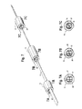
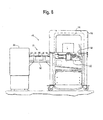
- FIG. 7 shows a plurality of twist necks 12, 14, 16 cooperating with one another, without tubes, to change the orientation of an associated strap S, which may be used, for example, in a strapping machine 48 to strap loads L together.
- Those of skill in the art will recognize that only one, two, four or more twist necks 12, 14, 16 may be used to change the orientation of the associates strap S, as well as the twist tube configuration 10 shown in FIGS. 1-2.
- the orientation of the associated strap S may need to change during the strapping operation.
- the orientation of the strap S often changes when the strap is being fed from the supply source 50 to the strapping head 52 of the strapping machine 48.
- the support structure 62 may comprise a desk top 58 that also supports the strapping head 52, the frame 56, which supports the chute 54, or any other type of support structure.
- the associated strap S enters the ingress opening 32 of the first twist neck 12 in a first orientation.
- the associated strap S then is gradually urged through the tapering portion 26 and into the pathway 34, as shown in FIGS. 3-6. If the pathway 34 is in the same orientation as the associated strap S was prior to entering the pathway, as is shown in FIGS. 7 and 7A, the orientation of the associated strap does not change.
- the associated strap S enters the ingress opening 32 of the second neck 14 and is gradually biased into a second orientation as it is urged into the second tapering portion 26 and eventually into the second pathway 34, which is in the second orientation.
- the tapering portion 26 may define any shape.
- the tapering portion 26 includes at its near end 28 the ingress opening 32, which defines any cross-sectional shape and, in the preferred embodiments shown, defines a circular shape.
- the ingress opening 32 preferably has a larger cross sectional area than the cross sectional area of any portion of the pathway 34. In this manner, the ingress opening 32 may receive the associated strap S in a variety of orientations. As shown in FIG.
- the twist neck 12, 14, 16 is configured so that the angle a between the orientation the associated strap S is received in and enters the twist neck and the orientation the associated strap exits the twist neck is as large as thirty degrees. In other embodiments not shown, the angle may be greater than thirty degrees.
- the associated strap S is then gradually biased into the orientation of the pathway 34 as it is urged through the tapering portion 26 and into the pathway.
- the pathway 34 has a length and a substantially uniform cross-sectional area that defines a strap shape.
- the strap shape is substantially similar to a cross sectional shape of the associated strap S.
- the cross sectional shape of the pathway preferably provides only about enough space for the associated strap S to enter the pathway 34 in one orientation, which is the orientation of the pathway.
- the associated strap S will exit the egress opening 40 at the distal end 38 of the pathway 34 in a second orientation, which is the same orientation of the pathway 34 of the second twist neck 14.
- the orientation of the associated strap S may be manipulated yet again by a third twist neck 16 by the same process described above. Changing the strap orientations may be repeated as many times as required by a user.
- twist neck 12, 14, 16 may turn the twist neck 12, 14, 16, thus changing the orientation of the pathway 34 and the associated strap as it is urged through the twist neck.
- the coupling portions 42, 44, ingress portion 22, and the middle portion 24 are integral with one another.
- the twist neck 12, 14, 16 should have at least one degree of movement to allow the user to turn the entire twist neck.
- the coupling portions 42, 44, ingress portion 22 and middle portion 24 may be removably and twistably connected to one another.
- the coupling portions 42, 44 may be removably connected to the ingress and middle portions 22, 24.
- the middle portion may be turned with respect to the ingress portion without twisting the entire twist neck 12, 14, 16.
- This allows one to fix the twist neck 12, 14, 16 to a support structure 62 so that the ingress portion 22 has zero degrees of freedom - but still allows a user to twist the middle portion 24 and the pathway 34 formed therein.
- the user may then change the orientation of the pathway 34 and, thus, the associated strap S as it passes through the pathway- even though the twist neck 12, 14, 16 is fixed in a manner that provides zero degrees of freedom to the ingress portion 22.
- the twist neck can be manipulated to change the orientation of the associated strap by thirty degrees. In other embodiments not shown, the twist necks may be manipulated a greater or lesser amount.
Landscapes
- Engineering & Computer Science (AREA)
- Mechanical Engineering (AREA)
- Basic Packing Technique (AREA)
- Purses, Travelling Bags, Baskets, Or Suitcases (AREA)
Applications Claiming Priority (1)
| Application Number | Priority Date | Filing Date | Title |
|---|---|---|---|
| US11/163,994 US7222565B1 (en) | 2005-11-07 | 2005-11-07 | Twist neck |
Publications (3)
| Publication Number | Publication Date |
|---|---|
| EP1783053A2 true EP1783053A2 (de) | 2007-05-09 |
| EP1783053A3 EP1783053A3 (de) | 2008-02-27 |
| EP1783053B1 EP1783053B1 (de) | 2010-01-06 |
Family
ID=37692440
Family Applications (1)
| Application Number | Title | Priority Date | Filing Date |
|---|---|---|---|
| EP06122867A Not-in-force EP1783053B1 (de) | 2005-11-07 | 2006-10-24 | Vorrichtung zum Ändern der Orientierung eines Umreifungsbandes |
Country Status (3)
| Country | Link |
|---|---|
| US (1) | US7222565B1 (de) |
| EP (1) | EP1783053B1 (de) |
| DE (1) | DE602006011556D1 (de) |
Cited By (1)
| Publication number | Priority date | Publication date | Assignee | Title |
|---|---|---|---|---|
| WO2014172279A1 (en) * | 2013-04-16 | 2014-10-23 | Signode International Ip Holdings Llc | Supported strap twist device |
Families Citing this family (1)
| Publication number | Priority date | Publication date | Assignee | Title |
|---|---|---|---|---|
| DE102020133610A1 (de) | 2020-12-15 | 2022-06-15 | Liebherr-Werk Bischofshofen Gmbh | Vorrichtung und Verfahren zum sicheren Interagieren von unbemannten Lademaschinen und bemannten Fahrzeugen und Personen |
Citations (1)
| Publication number | Priority date | Publication date | Assignee | Title |
|---|---|---|---|---|
| EP1541470A1 (de) | 2003-12-09 | 2005-06-15 | SIGNODE BERNPAK GmbH | Vorrichtung zum Längsumreifen eines Packstücks wie insbesondere eines Stapels von Zeitungen, Magazinen od.dgl. |
Family Cites Families (5)
| Publication number | Priority date | Publication date | Assignee | Title |
|---|---|---|---|---|
| US3447447A (en) * | 1967-02-21 | 1969-06-03 | Stanley Works | Strapping mechanism |
| DE3909223A1 (de) * | 1989-03-21 | 1990-10-18 | Forsch Entwicklung Wirtschaftl | Umreifungsmaschine zum verpacken von packstuecken beliebiger art und groesse |
| US5078057A (en) * | 1990-01-05 | 1992-01-07 | Illinois Tool Works Inc. | Binding machine, such as strapping machine |
| DE59202402D1 (de) * | 1991-11-30 | 1995-07-06 | Georg Lang | Vorrichtung zum Umreifen eines Packgutes mittels eines Bandes. |
| DE4230730B4 (de) * | 1992-09-14 | 2005-05-25 | Georg Lang | Umreifungsmaschine mit einem Bandführungsrahmen |
-
2005
- 2005-11-07 US US11/163,994 patent/US7222565B1/en not_active Expired - Fee Related
-
2006
- 2006-10-24 EP EP06122867A patent/EP1783053B1/de not_active Not-in-force
- 2006-10-24 DE DE602006011556T patent/DE602006011556D1/de active Active
Patent Citations (1)
| Publication number | Priority date | Publication date | Assignee | Title |
|---|---|---|---|---|
| EP1541470A1 (de) | 2003-12-09 | 2005-06-15 | SIGNODE BERNPAK GmbH | Vorrichtung zum Längsumreifen eines Packstücks wie insbesondere eines Stapels von Zeitungen, Magazinen od.dgl. |
Cited By (2)
| Publication number | Priority date | Publication date | Assignee | Title |
|---|---|---|---|---|
| WO2014172279A1 (en) * | 2013-04-16 | 2014-10-23 | Signode International Ip Holdings Llc | Supported strap twist device |
| US9238516B2 (en) | 2013-04-16 | 2016-01-19 | Signode Industrial Group Llc | Supported strap twist device |
Also Published As
| Publication number | Publication date |
|---|---|
| DE602006011556D1 (de) | 2010-02-25 |
| US7222565B1 (en) | 2007-05-29 |
| EP1783053A3 (de) | 2008-02-27 |
| US20070101872A1 (en) | 2007-05-10 |
| EP1783053B1 (de) | 2010-01-06 |
Similar Documents
| Publication | Publication Date | Title |
|---|---|---|
| US4294233A (en) | Slack absorbing device for an endoscope | |
| DE69616761T2 (de) | Verfahren und vorrichtung zum umreifen von gegenständen | |
| CA2350569C (en) | Compact creel | |
| AU7983398A (en) | Catheter reinforced to prevent luminal collapse and tensile failure | |
| TW334376B (en) | Filler material guide nozzle assembly | |
| US9238516B2 (en) | Supported strap twist device | |
| EP1655182A3 (de) | Vorhang-Airbageinrichtung | |
| EP1783053B1 (de) | Vorrichtung zum Ändern der Orientierung eines Umreifungsbandes | |
| EP1493856A3 (de) | Verfahren und Spannvorrichtung zum Stabilisieren und Regeln der Spannung eines Fadens der von einer Spule abgewickelt wird. | |
| KR101245420B1 (ko) | 신장소재를 형성하기 위한 장치 및 방법 | |
| JPH089840A (ja) | 中通し竿 | |
| US5243742A (en) | Warp supplying apparatus for a warp threading machine | |
| CN220028241U (zh) | 一种用于拉丝设备的收卷装置 | |
| US5082031A (en) | Flexible cable intermediate support for a heddle frame | |
| CN217414417U (zh) | 一种管桩张拉工装 | |
| EP1954617B1 (de) | Saugluftdüse für eine textilmaschine | |
| KR100361358B1 (ko) | 중통낚시대 | |
| AU7422698A (en) | Machine for making air cushions for packaging | |
| JP4149321B2 (ja) | 釣竿 | |
| JPH10192580A (ja) | 多針刺繍ミシン | |
| CA2026428A1 (en) | Fiber payout machine | |
| JP2004175505A (ja) | 光ファイバの廃却装置及び廃却方法 | |
| JPH05139407A (ja) | 梱包機の案内枠 | |
| JPH07125719A (ja) | 物品の結束装置 | |
| KR20230112569A (ko) | 실 공급 장치, 케이블링 머신의 워크스테이션, 및 공급 방법 |
Legal Events
| Date | Code | Title | Description |
|---|---|---|---|
| PUAI | Public reference made under article 153(3) epc to a published international application that has entered the european phase |
Free format text: ORIGINAL CODE: 0009012 |
|
| AK | Designated contracting states |
Kind code of ref document: A2 Designated state(s): AT BE BG CH CY CZ DE DK EE ES FI FR GB GR HU IE IS IT LI LT LU LV MC NL PL PT RO SE SI SK TR |
|
| AX | Request for extension of the european patent |
Extension state: AL BA HR MK YU |
|
| PUAL | Search report despatched |
Free format text: ORIGINAL CODE: 0009013 |
|
| AK | Designated contracting states |
Kind code of ref document: A3 Designated state(s): AT BE BG CH CY CZ DE DK EE ES FI FR GB GR HU IE IS IT LI LT LU LV MC NL PL PT RO SE SI SK TR |
|
| AX | Request for extension of the european patent |
Extension state: AL BA HR MK YU |
|
| RIC1 | Information provided on ipc code assigned before grant |
Ipc: B65B 13/06 20060101ALI20080124BHEP Ipc: B65B 13/18 20060101AFI20070208BHEP |
|
| 17P | Request for examination filed |
Effective date: 20080818 |
|
| AKX | Designation fees paid |
Designated state(s): CH DE ES FR IT LI |
|
| 17Q | First examination report despatched |
Effective date: 20081030 |
|
| GRAP | Despatch of communication of intention to grant a patent |
Free format text: ORIGINAL CODE: EPIDOSNIGR1 |
|
| GRAS | Grant fee paid |
Free format text: ORIGINAL CODE: EPIDOSNIGR3 |
|
| GRAA | (expected) grant |
Free format text: ORIGINAL CODE: 0009210 |
|
| AK | Designated contracting states |
Kind code of ref document: B1 Designated state(s): CH DE ES FR IT LI |
|
| REG | Reference to a national code |
Ref country code: CH Ref legal event code: EP |
|
| REF | Corresponds to: |
Ref document number: 602006011556 Country of ref document: DE Date of ref document: 20100225 Kind code of ref document: P |
|
| PG25 | Lapsed in a contracting state [announced via postgrant information from national office to epo] |
Ref country code: ES Free format text: LAPSE BECAUSE OF FAILURE TO SUBMIT A TRANSLATION OF THE DESCRIPTION OR TO PAY THE FEE WITHIN THE PRESCRIBED TIME-LIMIT Effective date: 20100417 |
|
| PLBE | No opposition filed within time limit |
Free format text: ORIGINAL CODE: 0009261 |
|
| STAA | Information on the status of an ep patent application or granted ep patent |
Free format text: STATUS: NO OPPOSITION FILED WITHIN TIME LIMIT |
|
| 26N | No opposition filed |
Effective date: 20101007 |
|
| PG25 | Lapsed in a contracting state [announced via postgrant information from national office to epo] |
Ref country code: IT Free format text: LAPSE BECAUSE OF FAILURE TO SUBMIT A TRANSLATION OF THE DESCRIPTION OR TO PAY THE FEE WITHIN THE PRESCRIBED TIME-LIMIT Effective date: 20100106 |
|
| REG | Reference to a national code |
Ref country code: CH Ref legal event code: PL |
|
| PG25 | Lapsed in a contracting state [announced via postgrant information from national office to epo] |
Ref country code: LI Free format text: LAPSE BECAUSE OF NON-PAYMENT OF DUE FEES Effective date: 20101031 Ref country code: FR Free format text: LAPSE BECAUSE OF NON-PAYMENT OF DUE FEES Effective date: 20101102 Ref country code: CH Free format text: LAPSE BECAUSE OF NON-PAYMENT OF DUE FEES Effective date: 20101031 |
|
| REG | Reference to a national code |
Ref country code: FR Ref legal event code: ST Effective date: 20110630 |
|
| REG | Reference to a national code |
Ref country code: DE Ref legal event code: R119 Ref document number: 602006011556 Country of ref document: DE Effective date: 20110502 |
|
| PG25 | Lapsed in a contracting state [announced via postgrant information from national office to epo] |
Ref country code: DE Free format text: LAPSE BECAUSE OF NON-PAYMENT OF DUE FEES Effective date: 20110502 |