EP1782879A1 - Fuel deoxygenation system with multi-layer oxygen permeable membrane - Google Patents
Fuel deoxygenation system with multi-layer oxygen permeable membrane Download PDFInfo
- Publication number
- EP1782879A1 EP1782879A1 EP06255609A EP06255609A EP1782879A1 EP 1782879 A1 EP1782879 A1 EP 1782879A1 EP 06255609 A EP06255609 A EP 06255609A EP 06255609 A EP06255609 A EP 06255609A EP 1782879 A1 EP1782879 A1 EP 1782879A1
- Authority
- EP
- European Patent Office
- Prior art keywords
- fuel
- oxygen
- recited
- layer
- channel
- Prior art date
- Legal status (The legal status is an assumption and is not a legal conclusion. Google has not performed a legal analysis and makes no representation as to the accuracy of the status listed.)
- Granted
Links
Images




Classifications
-
- B—PERFORMING OPERATIONS; TRANSPORTING
- B01—PHYSICAL OR CHEMICAL PROCESSES OR APPARATUS IN GENERAL
- B01D—SEPARATION
- B01D19/00—Degasification of liquids
-
- B—PERFORMING OPERATIONS; TRANSPORTING
- B01—PHYSICAL OR CHEMICAL PROCESSES OR APPARATUS IN GENERAL
- B01D—SEPARATION
- B01D19/00—Degasification of liquids
- B01D19/0031—Degasification of liquids by filtration
-
- B—PERFORMING OPERATIONS; TRANSPORTING
- B01—PHYSICAL OR CHEMICAL PROCESSES OR APPARATUS IN GENERAL
- B01D—SEPARATION
- B01D53/00—Separation of gases or vapours; Recovering vapours of volatile solvents from gases; Chemical or biological purification of waste gases, e.g. engine exhaust gases, smoke, fumes, flue gases, aerosols
- B01D53/22—Separation of gases or vapours; Recovering vapours of volatile solvents from gases; Chemical or biological purification of waste gases, e.g. engine exhaust gases, smoke, fumes, flue gases, aerosols by diffusion
-
- B—PERFORMING OPERATIONS; TRANSPORTING
- B01—PHYSICAL OR CHEMICAL PROCESSES OR APPARATUS IN GENERAL
- B01D—SEPARATION
- B01D53/00—Separation of gases or vapours; Recovering vapours of volatile solvents from gases; Chemical or biological purification of waste gases, e.g. engine exhaust gases, smoke, fumes, flue gases, aerosols
- B01D53/22—Separation of gases or vapours; Recovering vapours of volatile solvents from gases; Chemical or biological purification of waste gases, e.g. engine exhaust gases, smoke, fumes, flue gases, aerosols by diffusion
- B01D53/228—Separation of gases or vapours; Recovering vapours of volatile solvents from gases; Chemical or biological purification of waste gases, e.g. engine exhaust gases, smoke, fumes, flue gases, aerosols by diffusion characterised by specific membranes
-
- B—PERFORMING OPERATIONS; TRANSPORTING
- B01—PHYSICAL OR CHEMICAL PROCESSES OR APPARATUS IN GENERAL
- B01D—SEPARATION
- B01D61/00—Processes of separation using semi-permeable membranes, e.g. dialysis, osmosis or ultrafiltration; Apparatus, accessories or auxiliary operations specially adapted therefor
-
- B—PERFORMING OPERATIONS; TRANSPORTING
- B01—PHYSICAL OR CHEMICAL PROCESSES OR APPARATUS IN GENERAL
- B01D—SEPARATION
- B01D63/00—Apparatus in general for separation processes using semi-permeable membranes
- B01D63/08—Flat membrane modules
- B01D63/082—Flat membrane modules comprising a stack of flat membranes
- B01D63/0822—Plate-and-frame devices
-
- B—PERFORMING OPERATIONS; TRANSPORTING
- B01—PHYSICAL OR CHEMICAL PROCESSES OR APPARATUS IN GENERAL
- B01D—SEPARATION
- B01D65/00—Accessories or auxiliary operations, in general, for separation processes or apparatus using semi-permeable membranes
- B01D65/08—Prevention of membrane fouling or of concentration polarisation
-
- B—PERFORMING OPERATIONS; TRANSPORTING
- B01—PHYSICAL OR CHEMICAL PROCESSES OR APPARATUS IN GENERAL
- B01D—SEPARATION
- B01D69/00—Semi-permeable membranes for separation processes or apparatus characterised by their form, structure or properties; Manufacturing processes specially adapted therefor
- B01D69/06—Flat membranes
- B01D69/061—Membrane bags or membrane cushions
-
- B—PERFORMING OPERATIONS; TRANSPORTING
- B01—PHYSICAL OR CHEMICAL PROCESSES OR APPARATUS IN GENERAL
- B01D—SEPARATION
- B01D69/00—Semi-permeable membranes for separation processes or apparatus characterised by their form, structure or properties; Manufacturing processes specially adapted therefor
- B01D69/12—Composite membranes; Ultra-thin membranes
- B01D69/1216—Three or more layers
-
- B—PERFORMING OPERATIONS; TRANSPORTING
- B01—PHYSICAL OR CHEMICAL PROCESSES OR APPARATUS IN GENERAL
- B01D—SEPARATION
- B01D71/00—Semi-permeable membranes for separation processes or apparatus characterised by the material; Manufacturing processes specially adapted therefor
- B01D71/06—Organic material
- B01D71/30—Polyalkenyl halides
- B01D71/32—Polyalkenyl halides containing fluorine atoms
-
- B—PERFORMING OPERATIONS; TRANSPORTING
- B64—AIRCRAFT; AVIATION; COSMONAUTICS
- B64D—EQUIPMENT FOR FITTING IN OR TO AIRCRAFT; FLIGHT SUITS; PARACHUTES; ARRANGEMENT OR MOUNTING OF POWER PLANTS OR PROPULSION TRANSMISSIONS IN AIRCRAFT
- B64D37/00—Arrangements in connection with fuel supply for power plant
- B64D37/32—Safety measures not otherwise provided for, e.g. preventing explosive conditions
-
- B—PERFORMING OPERATIONS; TRANSPORTING
- B01—PHYSICAL OR CHEMICAL PROCESSES OR APPARATUS IN GENERAL
- B01D—SEPARATION
- B01D2321/00—Details relating to membrane cleaning, regeneration, sterilization or to the prevention of fouling
- B01D2321/02—Forward flushing
-
- F—MECHANICAL ENGINEERING; LIGHTING; HEATING; WEAPONS; BLASTING
- F23—COMBUSTION APPARATUS; COMBUSTION PROCESSES
- F23K—FEEDING FUEL TO COMBUSTION APPARATUS
- F23K2900/00—Special features of, or arrangements for fuel supplies
- F23K2900/05082—Removing gaseous substances from liquid fuel line, e.g. oxygen
-
- Y—GENERAL TAGGING OF NEW TECHNOLOGICAL DEVELOPMENTS; GENERAL TAGGING OF CROSS-SECTIONAL TECHNOLOGIES SPANNING OVER SEVERAL SECTIONS OF THE IPC; TECHNICAL SUBJECTS COVERED BY FORMER USPC CROSS-REFERENCE ART COLLECTIONS [XRACs] AND DIGESTS
- Y02—TECHNOLOGIES OR APPLICATIONS FOR MITIGATION OR ADAPTATION AGAINST CLIMATE CHANGE
- Y02T—CLIMATE CHANGE MITIGATION TECHNOLOGIES RELATED TO TRANSPORTATION
- Y02T50/00—Aeronautics or air transport
- Y02T50/40—Weight reduction
Definitions
- the present invention relates to stabilizing fuel by deoxygenation, and more particularly to deoxygenation through a composite oxygen permeable membrane which minimizes fuel absorption.
- Jet fuel is often utilized in aircraft as a coolant for various aircraft systems.
- the presence of dissolved oxygen in hydrocarbon jet fuels may be objectionable because the oxygen supports oxidation reactions that yield undesirable by-products.
- Dissolution of air in jet fuel results in an approximately 70 ppm oxygen concentration.
- aerated fuel is heated between 350°F (177°C) and 850°F (454°C) the oxygen initiates free radical reactions of the fuel resulting in deposits commonly referred to as "coke” or "coking.” Coke may be detrimental to the fuel lines and may inhibit combustion. The formation of such deposits may impair the normal functioning of a fuel system, either with respect to an intended heat exchange function or the efficient injection of fuel.
- FSU Fuel Stabilization Unit
- a disclosed fuel system for an energy conversion device includes a deoxygenator system with a composite oxygen permeable membrane formed from a multiple of material layers.
- the layers preferably include a sealant layer, an oxygen permeability layer and a porous backing layer.
- the layered composite oxygen permeable membrane maximizes the oxygen transfer rate yet minimizes the fuel leakage rate.
- a Teflon AF 1600/Teflon AF 2400 composite oxygen permeable membrane as described within the present invention has a total thickness of approximately 2 microns and exhibited a 20% improvement in jet fuel deoxygenation with only approximately 1/10 of the fuel leakage rate compared to an approximately 4 micron thick Teflon AF 2400 membrane with essentially no signs of performance degradation over 1000 hours of continuous operation. Similar performance improvement has been obtained using a Hyflon AD composite membrane.
- the present invention therefore provides for the deoxygenation of hydrocarbon fuel in a size and weight efficient system that minimizes fuel saturation of the oxygen permeable membrane.
- FIG. 1 illustrates a general schematic view of a fuel system 10 for an energy conversion device (ECD) 12.
- a deoxygenator system 14 receives liquid fuel F from a reservoir 16 such as a fuel tank.
- the fuel F is typically a hydrocarbon such as jet fuel.
- the ECD 12 may exist in a variety of forms in which the fuel, at some point prior to eventual use for processing, for combustion, or for some form of energy release, acquires sufficient heat to support autoxidation reactions and coking if dissolved oxygen is present to any significant extent in the fuel.
- ECD 12 is a gas turbine engine, and particularly such engines in aircraft.
- the fuel also serves as a coolant for one or more subsystems in the aircraft and becomes heated as it is delivered to fuel injectors immediately prior to combustion.
- a heat exchange section 18 represents a system through which the fuel passes in a heat exchange relationship. It should be understood that the heat exchange section 18 may be directly associated with the ECD 12 and/or distributed elsewhere in the larger system 10. The heat exchange system 18 may alternatively or additionally include a multiple of heat exchanges distributed throughout the system.
- fuel F stored in the reservoir 16 normally contains dissolved oxygen, possibly at a saturation level of 70 ppm.
- a fuel pump 20 draws the fuel F from the reservoir 16.
- the fuel pump 20 communicates with the reservoir 16 via a fuel reservoir conduit 22 and a valve 24 to a fuel inlet 26 of the deoxygenator system 14.
- the pressure applied by the fuel pump 20 assists in circulating the fuel F through the deoxygenator system 14 and other portions of the fuel system 10.
- oxygen is selectively removed into a vacuum or sweep gas system 28.
- the sweep gas can be any gas that is essentially free of oxygen.
- the deoxygenated fuel Fd flows from a fuel outlet 30 of the deoxygenation system 14 via a deoxygenated fuel conduit 32, to the heat exchange system 18 and to the ECD 12 such as the fuel injectors of a gas turbine engine.
- a portion of the deoxygenated fuel may be recirculated, as represented by recirculation conduit 33 to either the deoxygenation system 14 and/or the reservoir 16.
- the deoxygenator system 14 preferably includes a multiplicity of gas/fuel micro-channel assemblies 34 (Figure 2B).
- the assemblies 34 include a composite oxygen permeable membrane 36 between a fuel channel 38 and an oxygen receiving vacuum or sweep gas channel 40 which is preferably a mesh which permits the flow of nitrogen and/or another oxygen-free gas (Figure 3).
- the channels may be of various shapes and arrangements to provide a pressure differential, which maintains an oxygen concentration differential across the membrane to deoxygenate the fuel.
- the composite oxygen permeable membrane 36 preferably includes oxygen permeable membranes, which allow dissolved oxygen (and other gases) to diffuse through angstrom-size voids but exclude the larger fuel molecules, and permeable membranes which use a solution-diffusion mechanism to dissolve the oxygen (and/or other gases) and allow it (or them) to diffuse through the membrane, while excluding the fuel.
- oxygen permeable membranes which allow dissolved oxygen (and other gases) to diffuse through angstrom-size voids but exclude the larger fuel molecules
- permeable membranes which use a solution-diffusion mechanism to dissolve the oxygen (and/or other gases) and allow it (or them) to diffuse through the membrane, while excluding the fuel.
- Teflon AF which is an amorphous copolymer of perfluoro-2,2-dimethyl-1,3-dioxole (PDD) often identified under the trademark "Teflon AF" registered to E. I.
- Teflon AF 2400 and/or Teflon AF 1600 material is believed to use a solution-diffusion mechanism.
- one set of plates which forms one micro-channel assembly 34 of the deoxygenator system 14, includes a fuel plate assembly 44 sandwiched adjacent to the composite oxygen permeable membranes 36 which are supported by a porous support 42 such as non-woven polyester. It should be understood that the porous substrate, although schematically illustrated, may take various forms. Adjacent one or more assembly 34 is a separator plate 48. The separator plate 48 prevents fuel from leaking across the predefined fuel passages defined by the fuel plate assemblies 34.
- the deoxygenation system 14, irrespective of the number of micro-channel assemblies 34, is sealed by an interface plate 46 and an outer housing plate 50a, 50b, which respectively include the fuel inlet 26, the vacuum port 29, and the fuel outlet 30 (also illustrated in Figures 2A).
- the outer housing plates 50a, 50b are preferably attached together through a multitude of fasteners such as bolts or the like such that the micro-channel assemblies 34 are sandwiched therebetween.
- the outer housing plates 50a, 50b are preferably relatively rigid components which compress the micro-channel assemblies 34 such that sealing between plates are maintained thereby.
- Each fuel plate assembly 44 defines a portion of the fuel channel 38 between the inlet 26 and outlet 28.
- the vacuum port 29 ( Figure 2A) is in communication with a vacuum port 29f ( Figure 2B) through the interface plate 46 and the porous support 42. Vacuum creates a partial pressure gradient within each of the porous supports 42 to extract dissolved oxygen and other dissolved gases from the fuel channel 38 through the composite oxygen permeable membrane 36. The oxygen is expelled through the vacuum port 29.
- micro-channel assemblies 34 are determined by application-specific requirements, such as fuel type, fuel temperature, and mass flow demand from the engine. Further, different fuels containing differing amounts of dissolved oxygen may require differing amounts of deoxygenation to remove a desired amount of dissolved oxygen.
- Each fuel plate assembly 44 defines one fuel channel 38 ( Figure 3) between the inlet 26 and outlet 28 ( Figure 2A).
- the configuration of the fuel channel 38 is preferably defined to maximize fuel exposure to the composite oxygen permeable membrane 36 in order to maximize the amount of dissolved oxygen removed from the fuel. This may be accomplished by providing mixing and/or optimal flow patterns for the fuel.
- the fuel channels 38 are formed to maximize the amount of area of the fuel in contact with the permeable membrane in order to maximize the amount of dissolved oxygen removed from the fuel.
- the fuel channels 38 are preferably small enough that fuel is in contact with the composite oxygen permeable membrane 36 but also large enough so as to not restrict fuel flow.
- Each fuel plate assembly 44 includes a first fuel plate 52, a second fuel plate 54, and a fuel plate gasket 56 therebetween. It should be understood that the fuel plate assembly 44 disclosed in the illustrative embodiment illustrates only two fuel plates and a gasket for the sake of clarity, it should be understood that any number of plates may be located between the outer housing plates 50a, 50b. Preferably, all of the plates between the outer housing plates 50a, 50b are non-metallic.
- Each fuel plate assembly 44 includes a first fuel plate 52, a second fuel plate 54, and a fuel plate gasket 56 therebetween.
- the gasket 56 may be manufactured of a KAPTON® film manufactured by E. I. du Pont de Nemours and Company of Delaware USA. It should be understood that the fuel plate assembly 44 disclosed in the illustrative embodiment illustrates only two fuel plates and a gasket for the sake of clarity, it should be understood that any number of plate assemblies may be located between the outer housing plates 50a, 50b.
- the first fuel plate 52 and the second fuel plate 54 are preferably manufactured of a non-metallic material such as a thermoplastic or a polyphenylene sulfide (PPS). It should be understood that other plastics that are compatible with fuel and are electrically conductive (to prevent static charge buildup) may alternatively be utilized as well as materials which are machined rather than molded.
- a non-metallic material such as a thermoplastic or a polyphenylene sulfide (PPS).
- PPS polyphenylene sulfide
- the first fuel plate 52 and the second fuel plate 54 include flow impingement elements 55 ( Figures 2C and 3) which increase oxygen diffusivity.
- the flow impingement elements 55 are interleaved and alternate to provide the fuel channel 38 defined by the fuel plates 52, 54 with an intricate 3-dimensional flow characteristics (Figure 3).
- the flow impingement elements 55 on each fuel plate 52, 54 extend above the planar surface of their respective fuel plates 52, 54.
- the flow impingement elements 55 form a complete fuel channel 38 in which the flow impingement elements 55 from adjacent fuel plates 52, 54 extend ( Figure 3).
- the flow impingement elements 55 enhance deoxygenation by increasing transport of oxygen molecules to the oxygen permeable membrane surface, while the non-metallic material minimizes weight and sharp edges which may otherwise damage the oxygen permeable membranes 36.
- the flow impingement elements 55 of the deoxygenator system 14 enhance contact between fuel flow and the composite oxygen permeable membrane 36 to increase mass transport of dissolved oxygen.
- the composite oxygen permeable membrane 36 is formed from a multiple of layers.
- the layers include a sealant layer 60, an oxygen permeability layer 62 and a porous backing layer 64.
- the layered composite oxygen permeable membrane 36 maximizes the oxygen transfer rate and minimizes the fuel leakage rate to provide an efficient compromise based on product performance requirements. As the rate of fuel leakage through the membrane 36 is significantly lower than that of oxygen, the relatively thin sealant layer 60 has a dramatic impact in reducing the former without significantly affecting the latter.
- the porous backing layer 64 is preferably an asymmetric porous substrate approximately two thousands of an inch thick (0.051 mm).
- One such material is polyetherimide solution-cast by the method of phase inversion which provides skin pores on the order of approximately 40 nanometers such as that manufacture by Membrane Technology and Research, Inc. of Menlo Park, CA USA.
- the porous backing layer 64 supports the oxygen permeability layer 62 such that the oxygen permeability layer 62 may be coated thereto and essentially bridge the skin pores thereof.
- the oxygen permeability layer 62 is preferably approximately 1-5 microns thick, for example 1-2 microns thick for example 1.5 microns thick and is preferably manufactured of a polymer with high oxygen permeability such as Teflon AF 2400.
- the sealant layer 60 coats the oxygen permeability layer 62.
- the sealant layer 60 is preferably less than 1 micron thick and is preferably manufactured of an oxygen-permeable polymer with lower Free Fractional Volume (FFV), such as Teflon AF 1600, Hyflon AD, etc., which provides fuel-resistant properties to the adjacent fuel flow.
- FMV Free Fractional Volume
- the composite oxygen permeable membrane 36 is located adjacent the porous support 42 which provides stability to the composite oxygen permeable membrane 36 when sandwiched into the multiple of gas/fuel micro-channel assemblies 34 (Figure 2B). Also, the porous support 42 provides a cushion between the porous backing layer 64 and the vacuum mesh which defines the oxygen-receiving channel 40 ( Figure 3). It should be understood that various flow through layers such as mesh, a honeycomb structure or other gaseous transfer channel structures may alternatively or additionally be utilized with the present invention.
- the composite oxygen permeable membrane 36 need not be a planar member and that various shapes of the porous backing layer 64' ( Figure 5) may be coated with the sealant layer 60 and oxygen permeability layer 62 to meet various packaging considerations; provide various flow characteristics as well as form various fuel channel 38 components.
- a Teflon AF 1600/Teflon AF 2400 composite oxygen permeable membrane 36 as described above having a total thickness of approximately 2 microns exhibited a 20% improvement in jet fuel deoxygenation with only approximately 1/10 of the fuel leakage rate compared to an approximately 4 micron thick Teflon AF 2400 membrane with essentially no signs of performance degradation over 1000 hours of continuous operation.
Landscapes
- Chemical & Material Sciences (AREA)
- Chemical Kinetics & Catalysis (AREA)
- Engineering & Computer Science (AREA)
- Analytical Chemistry (AREA)
- General Chemical & Material Sciences (AREA)
- Oil, Petroleum & Natural Gas (AREA)
- Aviation & Aerospace Engineering (AREA)
- Water Supply & Treatment (AREA)
- Separation Using Semi-Permeable Membranes (AREA)
- Degasification And Air Bubble Elimination (AREA)
- Production Of Liquid Hydrocarbon Mixture For Refining Petroleum (AREA)
Abstract
Description
- The present invention relates to stabilizing fuel by deoxygenation, and more particularly to deoxygenation through a composite oxygen permeable membrane which minimizes fuel absorption.
- Jet fuel is often utilized in aircraft as a coolant for various aircraft systems. The presence of dissolved oxygen in hydrocarbon jet fuels may be objectionable because the oxygen supports oxidation reactions that yield undesirable by-products. Dissolution of air in jet fuel results in an approximately 70 ppm oxygen concentration. When aerated fuel is heated between 350°F (177°C) and 850°F (454°C) the oxygen initiates free radical reactions of the fuel resulting in deposits commonly referred to as "coke" or "coking." Coke may be detrimental to the fuel lines and may inhibit combustion. The formation of such deposits may impair the normal functioning of a fuel system, either with respect to an intended heat exchange function or the efficient injection of fuel.
- Various conventional fuel deoxygenation techniques are currently utilized to deoxygenate fuel. Typically, lowering the oxygen concentration to approximately 2 ppm is sufficient to overcome the coking problem.
- One conventional Fuel Stabilization Unit (FSU) utilized in aircraft removes oxygen from jet fuel by producing an oxygen partial pressure gradient across an oxygen permeable membrane. The membrane is in contact with fuel flow and is supported on a porous backing plate such that oxygen may be extracted from the fuel.
- Although quite effective, a very small amount of fuel may leak through the 6-12 angstrom-sized pores of the oxygen permeable membrane. The rate of fuel leakage is inversely proportional to the thickness of the membrane: however, the rate of oxygen removal is also inversely proportional to membrane thickness. Therefore, an increase in membrane thickness will reduce fuel leakages, but the increase will also proportionally reduce deoxygenation. However, minor fuel leakage may be detrimental in that, over a period of time, fuel may saturate the membrane, block the permeation of oxygen, and reduce deoxygenation efficiency thereof.
- Accordingly, it is desirable to provide for the deoxygenation of hydrocarbon fuel in a size and weight efficient system that minimizes fuel saturation of the oxygen permeable membrane.
- A disclosed fuel system for an energy conversion device according to the present invention includes a deoxygenator system with a composite oxygen permeable membrane formed from a multiple of material layers. The layers preferably include a sealant layer, an oxygen permeability layer and a porous backing layer. The layered composite oxygen permeable membrane maximizes the oxygen transfer rate yet minimizes the fuel leakage rate.
- Applicant has validated the composite oxygen permeable membrane of the present invention experimentally as compared to conventional single layer membranes. In particular, a Teflon AF 1600/Teflon AF 2400 composite oxygen permeable membrane as described within the present invention has a total thickness of approximately 2 microns and exhibited a 20% improvement in jet fuel deoxygenation with only approximately 1/10 of the fuel leakage rate compared to an approximately 4 micron thick Teflon AF 2400 membrane with essentially no signs of performance degradation over 1000 hours of continuous operation. Similar performance improvement has been obtained using a Hyflon AD composite membrane.
- The present invention therefore provides for the deoxygenation of hydrocarbon fuel in a size and weight efficient system that minimizes fuel saturation of the oxygen permeable membrane.
- The various features and advantages of this invention will become apparent to those skilled in the art from the following detailed description of the currently preferred embodiment. The drawings that accompany the detailed description can be briefly described as follows:
- Figure 1 is a general schematic block diagram of an energy conversion device (ECD) and an associated fuel system employing a fuel deoxygenator in accordance with the present invention;
- Figure 2A is an expanded perspective view of a deoxygenator system;
- Figure 2B is an exploded view of a deoxygenator system;
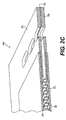
- Figure 2C is an expanded perspective view of a fuel plate assembly of the deoxygenator system of Figure 2B;
- Figure 3 is an expanded sectional view of a fuel plate assembly illustrating a fuel channel and an oxygen-receiving channel;
- Figure 4 is an expanded sectional view of the composite oxygen permeable porous membrane; and
- Figure 5 is an expanded sectional view of a non-planar composite oxygen permeable porous membrane.
- Figure 1 illustrates a general schematic view of a
fuel system 10 for an energy conversion device (ECD) 12. Adeoxygenator system 14 receives liquid fuel F from areservoir 16 such as a fuel tank. The fuel F is typically a hydrocarbon such as jet fuel. The ECD 12 may exist in a variety of forms in which the fuel, at some point prior to eventual use for processing, for combustion, or for some form of energy release, acquires sufficient heat to support autoxidation reactions and coking if dissolved oxygen is present to any significant extent in the fuel. - One form of the ECD 12 is a gas turbine engine, and particularly such engines in aircraft. Typically, the fuel also serves as a coolant for one or more subsystems in the aircraft and becomes heated as it is delivered to fuel injectors immediately prior to combustion.
- A
heat exchange section 18 represents a system through which the fuel passes in a heat exchange relationship. It should be understood that theheat exchange section 18 may be directly associated with theECD 12 and/or distributed elsewhere in thelarger system 10. Theheat exchange system 18 may alternatively or additionally include a multiple of heat exchanges distributed throughout the system. - As generally understood, fuel F stored in the
reservoir 16 normally contains dissolved oxygen, possibly at a saturation level of 70 ppm. Afuel pump 20 draws the fuel F from thereservoir 16. Thefuel pump 20 communicates with thereservoir 16 via afuel reservoir conduit 22 and a valve 24 to afuel inlet 26 of thedeoxygenator system 14. The pressure applied by thefuel pump 20 assists in circulating the fuel F through thedeoxygenator system 14 and other portions of thefuel system 10. As the fuel F passes through thedeoxygenator system 14, oxygen is selectively removed into a vacuum orsweep gas system 28. The sweep gas can be any gas that is essentially free of oxygen. - The deoxygenated fuel Fd flows from a
fuel outlet 30 of thedeoxygenation system 14 via adeoxygenated fuel conduit 32, to theheat exchange system 18 and to the ECD 12 such as the fuel injectors of a gas turbine engine. A portion of the deoxygenated fuel may be recirculated, as represented byrecirculation conduit 33 to either thedeoxygenation system 14 and/or thereservoir 16. It should be understood that although a particular component arrangement is disclosed in the illustrated embodiment, other arrangements will benefit from the instant invention. - Referring to Figure 2A, the
deoxygenator system 14 preferably includes a multiplicity of gas/fuel micro-channel assemblies 34 (Figure 2B). Theassemblies 34 include a composite oxygenpermeable membrane 36 between afuel channel 38 and an oxygen receiving vacuum orsweep gas channel 40 which is preferably a mesh which permits the flow of nitrogen and/or another oxygen-free gas (Figure 3). It should be understood that the channels may be of various shapes and arrangements to provide a pressure differential, which maintains an oxygen concentration differential across the membrane to deoxygenate the fuel. - The composite oxygen
permeable membrane 36 preferably includes oxygen permeable membranes, which allow dissolved oxygen (and other gases) to diffuse through angstrom-size voids but exclude the larger fuel molecules, and permeable membranes which use a solution-diffusion mechanism to dissolve the oxygen (and/or other gases) and allow it (or them) to diffuse through the membrane, while excluding the fuel. The family of Teflon AF which is an amorphous copolymer of perfluoro-2,2-dimethyl-1,3-dioxole (PDD) often identified under the trademark "Teflon AF" registered to E. I. DuPont de Nemours of Wilmington, Del., and the family of Hyflon AD which is a copolymer of 2,2,4-trifluoro-5-trifluoromethoxy-1,3- dioxole (TTD) registered to Solvay Solexis, Milan, Italy have proven to provide effective results for fuel deoxygenation. The Teflon AF 2400 and/or Teflon AF 1600 material is believed to use a solution-diffusion mechanism. - Referring to Figure 2B, one set of plates, which forms one
micro-channel assembly 34 of thedeoxygenator system 14, includes afuel plate assembly 44 sandwiched adjacent to the composite oxygenpermeable membranes 36 which are supported by aporous support 42 such as non-woven polyester. It should be understood that the porous substrate, although schematically illustrated, may take various forms. Adjacent one ormore assembly 34 is aseparator plate 48. Theseparator plate 48 prevents fuel from leaking across the predefined fuel passages defined by thefuel plate assemblies 34. Thedeoxygenation system 14, irrespective of the number ofmicro-channel assemblies 34, is sealed by aninterface plate 46 and an outer housing plate 50a, 50b, which respectively include thefuel inlet 26, thevacuum port 29, and the fuel outlet 30 (also illustrated in Figures 2A). The outer housing plates 50a, 50b are preferably attached together through a multitude of fasteners such as bolts or the like such that themicro-channel assemblies 34 are sandwiched therebetween. The outer housing plates 50a, 50b are preferably relatively rigid components which compress themicro-channel assemblies 34 such that sealing between plates are maintained thereby. Although illustrated as rectilinear in the illustrated embodiment, one of ordinary skill in the art will recognize that alternative shapes, sizes, or configurations are suitable and within the scope of the invention. - Each
fuel plate assembly 44 defines a portion of thefuel channel 38 between theinlet 26 andoutlet 28. The vacuum port 29 (Figure 2A) is in communication with a vacuum port 29f (Figure 2B) through theinterface plate 46 and theporous support 42. Vacuum creates a partial pressure gradient within each of theporous supports 42 to extract dissolved oxygen and other dissolved gases from thefuel channel 38 through the composite oxygenpermeable membrane 36. The oxygen is expelled through thevacuum port 29. - The specific quantity of
micro-channel assemblies 34 are determined by application-specific requirements, such as fuel type, fuel temperature, and mass flow demand from the engine. Further, different fuels containing differing amounts of dissolved oxygen may require differing amounts of deoxygenation to remove a desired amount of dissolved oxygen. - Each
fuel plate assembly 44 defines one fuel channel 38 (Figure 3) between theinlet 26 and outlet 28 (Figure 2A). The configuration of thefuel channel 38 is preferably defined to maximize fuel exposure to the composite oxygenpermeable membrane 36 in order to maximize the amount of dissolved oxygen removed from the fuel. This may be accomplished by providing mixing and/or optimal flow patterns for the fuel. Thefuel channels 38 are formed to maximize the amount of area of the fuel in contact with the permeable membrane in order to maximize the amount of dissolved oxygen removed from the fuel. Thefuel channels 38 are preferably small enough that fuel is in contact with the composite oxygenpermeable membrane 36 but also large enough so as to not restrict fuel flow. - Each
fuel plate assembly 44 includes afirst fuel plate 52, asecond fuel plate 54, and afuel plate gasket 56 therebetween. It should be understood that thefuel plate assembly 44 disclosed in the illustrative embodiment illustrates only two fuel plates and a gasket for the sake of clarity, it should be understood that any number of plates may be located between the outer housing plates 50a, 50b. Preferably, all of the plates between the outer housing plates 50a, 50b are non-metallic. - Each
fuel plate assembly 44 includes afirst fuel plate 52, asecond fuel plate 54, and afuel plate gasket 56 therebetween. Thegasket 56 may be manufactured of a KAPTON® film manufactured by E. I. du Pont de Nemours and Company of Delaware USA. It should be understood that thefuel plate assembly 44 disclosed in the illustrative embodiment illustrates only two fuel plates and a gasket for the sake of clarity, it should be understood that any number of plate assemblies may be located between the outer housing plates 50a, 50b. - The
first fuel plate 52 and thesecond fuel plate 54 are preferably manufactured of a non-metallic material such as a thermoplastic or a polyphenylene sulfide (PPS). It should be understood that other plastics that are compatible with fuel and are electrically conductive (to prevent static charge buildup) may alternatively be utilized as well as materials which are machined rather than molded. - The
first fuel plate 52 and thesecond fuel plate 54 include flow impingement elements 55 (Figures 2C and 3) which increase oxygen diffusivity. When thefuel plates flow impingement elements 55 are interleaved and alternate to provide thefuel channel 38 defined by thefuel plates flow impingement elements 55 on eachfuel plate respective fuel plates fuel plates gasket 56 to form thefuel plate assembly 44, theflow impingement elements 55 form acomplete fuel channel 38 in which theflow impingement elements 55 fromadjacent fuel plates - The flow impingement
elements 55 enhance deoxygenation by increasing transport of oxygen molecules to the oxygen permeable membrane surface, while the non-metallic material minimizes weight and sharp edges which may otherwise damage the oxygenpermeable membranes 36. The flow impingementelements 55 of thedeoxygenator system 14 enhance contact between fuel flow and the composite oxygenpermeable membrane 36 to increase mass transport of dissolved oxygen. - Referring to Figure 3, fuel flowing through the
fuel channel 38 is in contact with the composite oxygenpermeable membrane 36. Vacuum creates an oxygen partial pressure differential between the inner walls of thefuel channel 38 and the composite oxygenpermeable membrane 36 which causes diffusion of oxygen dissolved within the fuel to migrate through theporous support 42 which supports themembrane 36 and out of thedeoxygenator system 14 through the oxygen-receivingchannel 40 separate from thefuel channel 38. For further understanding of other aspects of one membrane based fuel deoxygenator system and associated components thereof, attention is directed toUnited States Patent No. 6,315,815 entitled Membrane based fuel deoxygenator;United States Patent No. 6,939,392 entitled System and method for thermal management andUnited States Patent No. 6,709,492 entitled PLANAR MEMBRANE DEOXYGENATOR which are assigned to the assignee of the instant invention and which are hereby incorporated herein in their entirety. - Referring to Figure 4, the composite oxygen
permeable membrane 36 is formed from a multiple of layers. Preferably, the layers include asealant layer 60, anoxygen permeability layer 62 and aporous backing layer 64. The layered composite oxygenpermeable membrane 36 maximizes the oxygen transfer rate and minimizes the fuel leakage rate to provide an efficient compromise based on product performance requirements. As the rate of fuel leakage through themembrane 36 is significantly lower than that of oxygen, the relativelythin sealant layer 60 has a dramatic impact in reducing the former without significantly affecting the latter. - The
porous backing layer 64 is preferably an asymmetric porous substrate approximately two thousands of an inch thick (0.051 mm). One such material is polyetherimide solution-cast by the method of phase inversion which provides skin pores on the order of approximately 40 nanometers such as that manufacture by Membrane Technology and Research, Inc. of Menlo Park, CA USA. - The
porous backing layer 64 supports theoxygen permeability layer 62 such that theoxygen permeability layer 62 may be coated thereto and essentially bridge the skin pores thereof. Theoxygen permeability layer 62 is preferably approximately 1-5 microns thick, for example 1-2 microns thick for example 1.5 microns thick and is preferably manufactured of a polymer with high oxygen permeability such as Teflon AF 2400. - The
sealant layer 60 coats theoxygen permeability layer 62. Thesealant layer 60 is preferably less than 1 micron thick and is preferably manufactured of an oxygen-permeable polymer with lower Free Fractional Volume (FFV), such as Teflon AF 1600, Hyflon AD, etc., which provides fuel-resistant properties to the adjacent fuel flow. - The composite oxygen
permeable membrane 36 is located adjacent theporous support 42 which provides stability to the composite oxygenpermeable membrane 36 when sandwiched into the multiple of gas/fuel micro-channel assemblies 34 (Figure 2B). Also, theporous support 42 provides a cushion between theporous backing layer 64 and the vacuum mesh which defines the oxygen-receiving channel 40 (Figure 3). It should be understood that various flow through layers such as mesh, a honeycomb structure or other gaseous transfer channel structures may alternatively or additionally be utilized with the present invention. - It should be understood that the composite oxygen
permeable membrane 36 need not be a planar member and that various shapes of the porous backing layer 64' (Figure 5) may be coated with thesealant layer 60 andoxygen permeability layer 62 to meet various packaging considerations; provide various flow characteristics as well as formvarious fuel channel 38 components. - Applicant has validated the composite oxygen
permeable membrane 36 of the present invention experimentally as compared to conventional single layer membranes. In particular, a Teflon AF 1600/Teflon AF 2400 composite oxygenpermeable membrane 36 as described above having a total thickness of approximately 2 microns exhibited a 20% improvement in jet fuel deoxygenation with only approximately 1/10 of the fuel leakage rate compared to an approximately 4 micron thick Teflon AF 2400 membrane with essentially no signs of performance degradation over 1000 hours of continuous operation. - The foregoing description is exemplary rather than defined by the limitations within. Many modifications and variations of the present invention are possible in light of the above teachings. The preferred embodiments of this invention have been disclosed, however, one of ordinary skill in the art would recognize that certain modifications would come within the scope of this invention. It is, therefore, to be understood that within the scope of the appended claims, the invention may be practiced otherwise than as specifically described. For that reason the following claims should be studied to determine the true scope and content of this invention.
Claims (20)
- A fuel system comprising:a fuel channel (38);an oxygen receiving channel (40); anda composite oxygen permeable membrane (36) in communication with said fuel channel (38) and said oxygen receiving channel (40).
- The fuel system as recited in claim 1, wherein said composite oxygen permeable membrane (36) includes a sealant layer (60) on an oxygen permeability layer (62), said sealant layer (60) facing said fuel channel (38).
- The fuel system as recited in claim 2, wherein said oxygen permeability layer (62) is supported on a porous backing layer (64).
- The fuel system as recited in claim 2 or 3, wherein said oxygen permeability layer (62) is between 1-5 microns thick.
- The fuel system as recited in claim 4, wherein said oxygen permeability layer (62) is approximately 1.5 microns thick.
- The fuel system as recited in claim 4 or 5, wherein said oxygen permeability layer (62) is manufactured of Teflon AF2400 (an amorphous copolymer of perfluoro-2,2-dimethyl-1,3-dioxole, PDD) or Hyflon AD (a copolymer of 2,2,4-trifluoro-5-trifluoromethoxy-1,3- dioxole, TTD).
- The fuel system as recited in claim 4 or 5, wherein said oxygen permeability layer (62) is manufactured of an amorphous copolymer of perfluoro-2,2-dimethyl-1,3-dioxole.
- The fuel system as recited in claim 4 or 5, wherein said oxygen permeability layer (62) is manufactured of PDD.
- The fuel system as recited in claim 4 or 5, wherein said oxygen permeability layer (62) is manufactured of Hyflon AD.
- The fuel system as recited in claim 4 or 5, wherein said oxygen permeability layer (62) is manufactured of a copolymer of 2,2,4-trifluoro-5-trifluoromethoxy-1,3-dioxole.
- The fuel system as recited in claim 4 or 5, wherein said oxygen permeability layer (62) is manufactured of TTD.
- The fuel system as recited in any of claims 2 to 11, wherein said sealant layer (60) is less than 1 micron thick.
- The fuel system as recited in any of claims 2 to 12, wherein said sealant layer (60) is manufactured of Teflon AF1600.
- The fuel system as recited in any of claims 2 to 12, wherein said sealant layer (60) is manufactured of HyflonAD.
- The fuel system as recited in any preceding claim, wherein said oxygen receiving channel (40) communicates gas essentially free of oxygen therethrough.
- The fuel system as recited in any preceding claim, wherein said oxygen receiving channel (40) includes a vacuum.
- A deoxygenation system (14) comprising:a first channel (38);a second channel (40); anda composite oxygen permeable membrane (36) in communication with said first channel (38) and said second channel (40), said composite oxygen permeable membrane (36) including a sealant layer (60) on an oxygen permeability layer (62) which is supported on a porous backing layer (64) such that said sealant layer (60) faces said first channel (38).
- The system as recited in claim 17, wherein said oxygen permeability layer (62) is between 1-5 microns thick and said sealant layer is less than 1 microns thick.
- The system as recited in claim 17 or 18, wherein said first channel (38) is a fuel channel.
- A method of minimizing dissolved oxygen from within a fuel system comprising the steps of:(1) locating a composite layer oxygen permeable membrane (36) having a sealant layer (60) adjacent a liquid fuel flow containing a dissolved oxygen; and(2) providing an oxygen concentration differential adjacent the composite layer oxygen permeable membrane (36) opposite the liquid fuel flow to draw oxygen from the liquid fuel flow through the composite layer oxygen permeable membrane (36).
Applications Claiming Priority (1)
| Application Number | Priority Date | Filing Date | Title |
|---|---|---|---|
| US11/265,845 US7615104B2 (en) | 2005-11-03 | 2005-11-03 | Fuel deoxygenation system with multi-layer oxygen permeable membrane |
Publications (2)
| Publication Number | Publication Date |
|---|---|
| EP1782879A1 true EP1782879A1 (en) | 2007-05-09 |
| EP1782879B1 EP1782879B1 (en) | 2013-06-05 |
Family
ID=37762480
Family Applications (1)
| Application Number | Title | Priority Date | Filing Date |
|---|---|---|---|
| EP06255609.7A Active EP1782879B1 (en) | 2005-11-03 | 2006-10-31 | Fuel deoxygenation system with multi-layer oxygen permeable membrane |
Country Status (6)
| Country | Link |
|---|---|
| US (1) | US7615104B2 (en) |
| EP (1) | EP1782879B1 (en) |
| JP (1) | JP2007126656A (en) |
| KR (1) | KR20070048115A (en) |
| CN (1) | CN1958115A (en) |
| CA (1) | CA2556207A1 (en) |
Cited By (1)
| Publication number | Priority date | Publication date | Assignee | Title |
|---|---|---|---|---|
| EP1810742B1 (en) * | 2006-01-18 | 2011-12-28 | United Technologies Corporation | Fuel deoxygenation system with non-metallic fuel plate assembly |
Families Citing this family (14)
| Publication number | Priority date | Publication date | Assignee | Title |
|---|---|---|---|---|
| US20080016846A1 (en) * | 2006-07-18 | 2008-01-24 | United Technologies Corporation | System and method for cooling hydrocarbon-fueled rocket engines |
| US9580185B2 (en) | 2012-01-20 | 2017-02-28 | Hamilton Sundstrand Corporation | Small engine cooled cooling air system |
| US8876946B2 (en) * | 2012-04-03 | 2014-11-04 | Hamilton Sundstrand Corporation | Combined fuel stabilization unit and heat exchanger |
| US9789972B2 (en) * | 2014-06-27 | 2017-10-17 | Hamilton Sundstrand Corporation | Fuel and thermal management system |
| US10329508B2 (en) | 2014-07-25 | 2019-06-25 | Hamilton Sundstrand Corporation | Fuel additive and method of preparing the same |
| US10215097B2 (en) | 2015-12-08 | 2019-02-26 | General Electric Company | Thermal management system |
| US20190023411A1 (en) * | 2017-07-24 | 2019-01-24 | Hamilton Sundstrand Corporation | Hydrocarbon fuel system |
| US10576397B2 (en) | 2017-08-22 | 2020-03-03 | Hamilton Sundstrand Corporation | Hollow-fiber membrane for fuel degassing |
| CN108530108A (en) * | 2018-04-04 | 2018-09-14 | 南京工业大学 | Ceramic oxygen permeable membrane composite structure and preparation method thereof |
| WO2020132656A1 (en) | 2018-12-22 | 2020-06-25 | Air Liquide Advanced Technologies U.S. Llc | Composite hollow fiber membranes for jet fuel de-oxygenation |
| KR20210139430A (en) | 2019-03-26 | 2021-11-22 | 버슘머트리얼즈 유에스, 엘엘씨 | Degassing apparatus, degassing system and method of using same |
| US11866182B2 (en) | 2020-05-01 | 2024-01-09 | General Electric Company | Fuel delivery system having a fuel oxygen reduction unit |
| US11352960B2 (en) | 2020-05-01 | 2022-06-07 | General Electric Company | Fuel oxygen reduction unit |
| KR20220063393A (en) | 2020-11-10 | 2022-05-17 | 주식회사 엘지에너지솔루션 | Secondary battery comprising gas scavenging member |
Citations (4)
| Publication number | Priority date | Publication date | Assignee | Title |
|---|---|---|---|---|
| WO1998035739A1 (en) | 1997-02-14 | 1998-08-20 | Raychem Corporation | Method for extracting gases dissolved in a liquid |
| US6709492B1 (en) | 2003-04-04 | 2004-03-23 | United Technologies Corporation | Planar membrane deoxygenator |
| EP1568403A1 (en) | 2004-02-25 | 2005-08-31 | United Technologies Corporation | Method for producing a non-porous membrane |
| EP1579901A1 (en) | 2004-03-22 | 2005-09-28 | United Technologies Corporation | Method of suppressing coke in endothermic fuel processing |
Family Cites Families (103)
| Publication number | Priority date | Publication date | Assignee | Title |
|---|---|---|---|---|
| US148164A (en) * | 1874-03-03 | Improvement in the manufacture of india-rubber articles | ||
| US94463A (en) * | 1869-09-07 | Improvement in propellers tor vessels | ||
| US219637A (en) * | 1879-09-16 | Improvement in the manufacture of chromates-of-eoiash and soda | ||
| US28988A (en) * | 1860-07-03 | Detaching horses ekom vehicles | ||
| US151156A (en) * | 1874-05-19 | Improvement in dumping cars | ||
| US195385A (en) * | 1877-09-18 | Improvement in incased glass vessels | ||
| US35093A (en) * | 1862-04-29 | Improvement in combined sword and pistol | ||
| US161785A (en) * | 1875-04-06 | Improvement in riding-saddles | ||
| US25696A (en) * | 1859-10-04 | Machine fob trimming- wall-paper | ||
| US50786A (en) * | 1865-11-07 | Improved mode of lubricating journals | ||
| US116015A (en) * | 1871-06-20 | Improvement in earth-closets | ||
| US4371385A (en) * | 1981-04-28 | 1983-02-01 | Cobe Laboratories, Inc. | Deaerating liquid |
| US4516984A (en) * | 1983-11-08 | 1985-05-14 | Emory University | Degassing process and apparatus for removal of oxygen |
| US4602923A (en) * | 1984-04-03 | 1986-07-29 | Erwin J. Baumgartler | Apparatus for degasifying a liquid medium |
| JPS62204086A (en) * | 1986-03-04 | 1987-09-08 | 株式会社エルマ、シーアール | Pipe |
| JPS63151307A (en) | 1986-12-15 | 1988-06-23 | Toshiba Corp | Degassing treatment apparatus |
| JPH069645B2 (en) | 1986-12-25 | 1994-02-09 | リグナイト株式会社 | Separation method of mixed solution |
| US5410052A (en) * | 1987-02-25 | 1995-04-25 | The Regents Of The University Of California | Symmetrical and unsymmetrical polyalkylamine metal complexes for ligand extraction and generation |
| US4955992A (en) * | 1987-06-26 | 1990-09-11 | Beckman Instruments, Inc. | Liquid degassing system |
| JPH0252005A (en) | 1988-08-12 | 1990-02-21 | Japan Gore Tex Inc | Deaeration mechanism |
| EP0360009B1 (en) * | 1988-08-20 | 1996-05-08 | Nitto Denko Corporation | Method of removing dissolved gas from liquid |
| JP2893530B2 (en) * | 1988-12-08 | 1999-05-24 | ジャパンゴアテックス株式会社 | Degassing membrane and degassing process |
| US5240853A (en) * | 1989-03-07 | 1993-08-31 | Oxyrase, Inc. | Apparatus and method for continuously removing oxygen from fluid streams using bacterial membranes |
| JP2774843B2 (en) | 1989-11-28 | 1998-07-09 | 日東電工株式会社 | Spiral type degassing module |
| JP2961665B2 (en) | 1989-12-25 | 1999-10-12 | 富士写真フイルム株式会社 | Degassing and degassing of liquid |
| EP0448973B1 (en) * | 1990-02-27 | 1995-12-20 | Toray Industries, Inc. | Spiral wound gas permeable membrane module and apparatus and method for using the same |
| US5019263A (en) | 1990-06-05 | 1991-05-28 | Mobil Oil Corp. | Membrane composed of a pure molecular sieve |
| US5053060A (en) * | 1990-06-29 | 1991-10-01 | Molecular Devices Corporation | Device and method for degassing, gassing and debubbling liquids |
| EP0493869A1 (en) | 1991-01-04 | 1992-07-08 | Japan Gore-Tex, Inc. | Apparatus for treating water |
| JPH0584474A (en) | 1991-09-26 | 1993-04-06 | Hitachi Plant Eng & Constr Co Ltd | Method and apparatus for removing dissolved oxygen |
| JPH05177117A (en) | 1991-10-23 | 1993-07-20 | Hisateru Takano | Substance exchange device |
| US5290237A (en) | 1992-01-17 | 1994-03-01 | Verkaart Wesley H | Orientation-independent device for removal of gas from a cellular fluid |
| JPH08906A (en) | 1992-05-06 | 1996-01-09 | Mikuni Kikai Kk | Degassing device |
| JPH05317605A (en) | 1992-05-26 | 1993-12-03 | Dainippon Ink & Chem Inc | Membrane vacuum degassing method and membrane vacuum degassing apparatus |
| CA2103620A1 (en) | 1992-08-14 | 1994-02-15 | Dorai Ramprasad | Method for recovering oxygen from oxygen-containing gaseous mixtures |
| WO1994016800A1 (en) | 1993-01-28 | 1994-08-04 | Tygola Pty. Ltd. | Perstraction with chemical reaction |
| US5340384A (en) * | 1993-03-05 | 1994-08-23 | Systec, Inc. | Vacuum degassing |
| EP0622475A1 (en) | 1993-04-29 | 1994-11-02 | Applied Materials, Inc. | Method and apparatus for degassing semiconductor processing liquids |
| JPH0780205A (en) | 1993-06-30 | 1995-03-28 | Miura Co Ltd | Selective degassing method and device |
| JPH0760005A (en) * | 1993-08-31 | 1995-03-07 | Miura Co Ltd | Dearation of liquid product |
| JPH07227504A (en) | 1994-02-17 | 1995-08-29 | Nomura Micro Sci Co Ltd | Dissolved oxygen removal method |
| DE4446270C1 (en) * | 1994-12-23 | 1996-02-29 | Hewlett Packard Gmbh | Liquid chromatography de-gasifier |
| FR2730484B1 (en) * | 1995-02-15 | 1997-05-09 | Schlumberger Ind Sa | DEGASSING SYSTEM FOR A HYDROCARBON DISPENSER |
| JPH08332306A (en) | 1995-06-06 | 1996-12-17 | Japan Gore Tex Inc | Degassing membrane and degassing module |
| DE59500094D1 (en) | 1995-06-19 | 1997-03-13 | Juergen Bastian | Minimization of the gas content in heat transfer and insulating liquids |
| FR2736329B1 (en) | 1995-07-05 | 1997-08-29 | Astra Plastique | CLOSING CAPE PROVIDED WITH A DEGASSING DEVICE, METHOD FOR MANUFACTURING SUCH A CAPE AND DEVICE FOR CARRYING OUT SAID METHOD |
| US5888275A (en) * | 1996-02-26 | 1999-03-30 | Japan Gore-Tex, Inc. | Assembly for deaeration of liquids |
| US5695545A (en) * | 1996-05-10 | 1997-12-09 | Hoechst Celanese Corporation | Degassing liquids: apparatus and method |
| US5876604A (en) * | 1996-10-24 | 1999-03-02 | Compact Membrane Systems, Inc | Method of gasifying or degasifying a liquid |
| JPH10174803A (en) | 1996-12-17 | 1998-06-30 | Hitachi Building Syst Co Ltd | Gas removal device in oil |
| US6623637B1 (en) | 1996-12-24 | 2003-09-23 | Kitz Corporation | Hollow-fiber membrane module |
| DE19704298C1 (en) | 1997-02-06 | 1999-01-14 | Jens Pannenborg | Process for degassing liquids by reducing the volume in the degassing chamber |
| JP3280880B2 (en) | 1997-02-07 | 2002-05-13 | 東京エレクトロン株式会社 | Degassing mechanism and processing apparatus using the same |
| DE19717043C2 (en) * | 1997-04-23 | 2003-05-22 | Daimler Chrysler Ag | Method for dewatering and / or degassing hydraulic fluids, device for carrying out the method and use of the device |
| US6447679B1 (en) | 1997-04-30 | 2002-09-10 | Mitsubishi Rayon Company, Limited | Hollow fiber membrane |
| US6106591A (en) * | 1997-06-23 | 2000-08-22 | Praxair Technology, Inc. | Process for reducing carbon production in solid electrolyte ionic conductor systems |
| JP3685289B2 (en) | 1997-06-26 | 2005-08-17 | 大日本インキ化学工業株式会社 | Liquid degassing module |
| JP4139456B2 (en) * | 1997-10-02 | 2008-08-27 | 三菱レイヨン株式会社 | Deaeration membrane |
| JPH11179167A (en) * | 1997-12-25 | 1999-07-06 | Nitto Denko Corp | Spiral type membrane module |
| CA2322949C (en) | 1998-02-06 | 2005-09-20 | Anjou Recherche | Hollow fiber membrane carpet manufacturing method, an elementary hollow fiber membrane carpet member and hollow fiber membrane carpet |
| JPH11244607A (en) | 1998-03-03 | 1999-09-14 | Mitsubishi Rayon Co Ltd | Degassing method and degassing device for chemical solution |
| JP2975000B2 (en) | 1998-04-10 | 1999-11-10 | 三菱レイヨン株式会社 | Composite hollow fiber membrane for artificial lung |
| DE69828594T2 (en) * | 1998-07-17 | 2005-06-16 | Agilent Technologies Inc., A Delaware Corp., Palo Alto | Device for degassing liquids |
| JP2000051606A (en) | 1998-08-07 | 2000-02-22 | Japan Organo Co Ltd | Gas permeation membrane apparatus |
| JP2000084368A (en) | 1998-09-08 | 2000-03-28 | Mitsubishi Rayon Co Ltd | Composite hollow fiber membrane for chemical solution deaeration |
| JP3500315B2 (en) | 1998-11-12 | 2004-02-23 | 東京エレクトロン株式会社 | Degassing device and degassing method |
| DE69930368T2 (en) | 1999-01-05 | 2006-10-19 | Erc Inc., Kawaguchi | Device for vacuum deaeration |
| JP2000262871A (en) | 1999-01-11 | 2000-09-26 | Kawamura Inst Of Chem Res | Microporous membrane separation device and its production |
| EP1148931B1 (en) | 1999-01-29 | 2006-06-28 | Entegris, Inc. | Hollow fiber membrane contactor |
| DE60029308T2 (en) | 1999-01-29 | 2007-07-19 | Entegris, Inc., Chaska | HALF-COLOR MEMBRANE AND PROCESS FOR MAKING IT |
| JP2000288366A (en) | 1999-04-02 | 2000-10-17 | Mitsubishi Rayon Co Ltd | Composite flat membrane |
| JP2000350902A (en) | 1999-06-09 | 2000-12-19 | Fuji Photo Film Co Ltd | Deaeration method |
| US6248157B1 (en) * | 1999-08-20 | 2001-06-19 | Systec Inc. | Vacuum degassing |
| US6315815B1 (en) * | 1999-12-16 | 2001-11-13 | United Technologies Corporation | Membrane based fuel deoxygenator |
| JP2001246232A (en) | 2000-03-03 | 2001-09-11 | Japan Gore Tex Inc | Gas permeable membrane device |
| US6402818B1 (en) * | 2000-06-02 | 2002-06-11 | Celgard Inc. | Degassing a liquid with a membrane contactor |
| US6540813B2 (en) * | 2000-06-13 | 2003-04-01 | Praxair Technology, Inc. | Method of preparing composite gas separation membranes from perfluoropolymers |
| JP2004508183A (en) | 2000-09-13 | 2004-03-18 | マイクロリス・コーポレイシヨン | Liquid filtration device |
| US6547859B1 (en) | 2000-11-21 | 2003-04-15 | Praxair Technology, Inc. | Process for making microporous membranes having selected gas-selective sites and the membranes so made |
| DE10111241A1 (en) | 2001-03-09 | 2002-09-12 | Man Nutzfahrzeuge Ag | Ventilation device, splash-proof, for gear housings, preferably in motor vehicles |
| US6558450B2 (en) | 2001-03-22 | 2003-05-06 | Celgard Inc. | Method for debubbling an ink |
| US6616841B2 (en) | 2001-06-21 | 2003-09-09 | Celgard Inc. | Hollow fiber membrane contactor |
| JP4587428B2 (en) | 2001-07-02 | 2010-11-24 | 三菱レイヨン株式会社 | Deaerator |
| US6596058B2 (en) | 2001-07-16 | 2003-07-22 | Systec, Inc. | Film degassing system |
| JP2003062403A (en) | 2001-08-24 | 2003-03-04 | Ebara Corp | Operating method for membrane degasifier |
| US20030148164A1 (en) | 2001-09-07 | 2003-08-07 | Koch Carol A. | Efficient fuel cell water transport plates |
| EP2275766A1 (en) | 2001-10-01 | 2011-01-19 | Entegris, Inc. | Tubular heat or mass exchange apparatus |
| WO2003036747A1 (en) | 2001-10-22 | 2003-05-01 | Protonex Technology Corporation | One-shot fabrication of membrane-based electrochemical cell stacks |
| JP2003200024A (en) | 2001-10-31 | 2003-07-15 | Sekisui Chem Co Ltd | module |
| US6749799B2 (en) | 2002-02-12 | 2004-06-15 | Adaptive Materials, Inc. | Method for preparation of solid state electrochemical device |
| WO2003072491A1 (en) | 2002-02-22 | 2003-09-04 | Chevron U.S.A. Inc. | Process for reducing metal catalyzed coke formation in hydrocarbon processing |
| JP2003245525A (en) | 2002-02-25 | 2003-09-02 | Sekisui Chem Co Ltd | module |
| WO2003080228A1 (en) | 2002-03-19 | 2003-10-02 | Mykrolis Corporation | Hollow fiber membrane contact apparatus and process |
| WO2003086573A1 (en) | 2002-04-08 | 2003-10-23 | Dominion Engineering, Inc. | Liquid degassing system for power plant system layup |
| JP2005535788A (en) | 2002-05-09 | 2005-11-24 | マサチューセッツ・インスティチュート・オブ・テクノロジー | Production of asymmetric membranes by hot filament chemical vapor deposition. |
| US7045231B2 (en) | 2002-05-22 | 2006-05-16 | Protonetics International, Inc. | Direct hydrocarbon reforming in protonic ceramic fuel cells by electrolyte steam permeation |
| AU2003253840A1 (en) | 2002-07-11 | 2004-02-02 | Pall Corporation | Uv treated membranes |
| US6953633B2 (en) | 2002-08-06 | 2005-10-11 | General Electric Company | Fiber cooling of fuel cells |
| US6682016B1 (en) * | 2002-09-05 | 2004-01-27 | Hamilton Sundstrand | Thermal management valve with drop-tight shutoff of return to tank |
| US6858145B2 (en) | 2002-09-12 | 2005-02-22 | Chemitreat Pte Ltd | Method of removing organic impurities from water |
| US7153343B2 (en) * | 2004-03-24 | 2006-12-26 | United Technologies Corporation | Fuel deoxygenation system |
| US7329305B2 (en) * | 2005-02-23 | 2008-02-12 | United Technologies Corporation | Membrane based de-oxygenator for process streams |
| US7465336B2 (en) * | 2005-06-09 | 2008-12-16 | United Technologies Corporation | Fuel deoxygenation system with non-planar plate members |
-
2005
- 2005-11-03 US US11/265,845 patent/US7615104B2/en active Active
-
2006
- 2006-08-14 CA CA002556207A patent/CA2556207A1/en not_active Abandoned
- 2006-09-14 KR KR1020060088775A patent/KR20070048115A/en not_active Abandoned
- 2006-10-30 JP JP2006293786A patent/JP2007126656A/en active Pending
- 2006-10-31 EP EP06255609.7A patent/EP1782879B1/en active Active
- 2006-11-03 CN CNA2006101432949A patent/CN1958115A/en active Pending
Patent Citations (4)
| Publication number | Priority date | Publication date | Assignee | Title |
|---|---|---|---|---|
| WO1998035739A1 (en) | 1997-02-14 | 1998-08-20 | Raychem Corporation | Method for extracting gases dissolved in a liquid |
| US6709492B1 (en) | 2003-04-04 | 2004-03-23 | United Technologies Corporation | Planar membrane deoxygenator |
| EP1568403A1 (en) | 2004-02-25 | 2005-08-31 | United Technologies Corporation | Method for producing a non-porous membrane |
| EP1579901A1 (en) | 2004-03-22 | 2005-09-28 | United Technologies Corporation | Method of suppressing coke in endothermic fuel processing |
Cited By (1)
| Publication number | Priority date | Publication date | Assignee | Title |
|---|---|---|---|---|
| EP1810742B1 (en) * | 2006-01-18 | 2011-12-28 | United Technologies Corporation | Fuel deoxygenation system with non-metallic fuel plate assembly |
Also Published As
| Publication number | Publication date |
|---|---|
| US7615104B2 (en) | 2009-11-10 |
| CA2556207A1 (en) | 2007-05-03 |
| JP2007126656A (en) | 2007-05-24 |
| US20070095206A1 (en) | 2007-05-03 |
| KR20070048115A (en) | 2007-05-08 |
| CN1958115A (en) | 2007-05-09 |
| EP1782879B1 (en) | 2013-06-05 |
Similar Documents
| Publication | Publication Date | Title |
|---|---|---|
| US7824470B2 (en) | Method for enhancing mass transport in fuel deoxygenation systems | |
| US7465336B2 (en) | Fuel deoxygenation system with non-planar plate members | |
| EP1810742B1 (en) | Fuel deoxygenation system with non-metallic fuel plate assembly | |
| EP1464376B1 (en) | Planar membrane deoxygenator | |
| US8177884B2 (en) | Fuel deoxygenator with porous support plate | |
| US7615104B2 (en) | Fuel deoxygenation system with multi-layer oxygen permeable membrane | |
| EP1810741B1 (en) | Fuel deoxygenator with non-planar fuel channel and oxygen permeable membrane | |
| KR100656871B1 (en) | Fuel Deoxygenation Device | |
| US7465335B2 (en) | Fuel deoxygenation system with textured oxygen permeable membrane | |
| EP1677888B1 (en) | System and method for thermal management | |
| US20050137441A1 (en) | Multi-stage fuel deoxygenator | |
| EP3434752A1 (en) | Fuel tank de-oxygenation system | |
| CA2545897A1 (en) | Fuel deoxygenation system with non-planar plate members | |
| EP3434347A1 (en) | Fuel tank de-oxygenation system |
Legal Events
| Date | Code | Title | Description |
|---|---|---|---|
| PUAI | Public reference made under article 153(3) epc to a published international application that has entered the european phase |
Free format text: ORIGINAL CODE: 0009012 |
|
| AK | Designated contracting states |
Kind code of ref document: A1 Designated state(s): AT BE BG CH CY CZ DE DK EE ES FI FR GB GR HU IE IS IT LI LT LU LV MC NL PL PT RO SE SI SK TR |
|
| AX | Request for extension of the european patent |
Extension state: AL BA HR MK YU |
|
| 17P | Request for examination filed |
Effective date: 20070628 |
|
| 17Q | First examination report despatched |
Effective date: 20070730 |
|
| AKX | Designation fees paid |
Designated state(s): DE FR GB |
|
| GRAP | Despatch of communication of intention to grant a patent |
Free format text: ORIGINAL CODE: EPIDOSNIGR1 |
|
| GRAP | Despatch of communication of intention to grant a patent |
Free format text: ORIGINAL CODE: EPIDOSNIGR1 |
|
| GRAS | Grant fee paid |
Free format text: ORIGINAL CODE: EPIDOSNIGR3 |
|
| GRAA | (expected) grant |
Free format text: ORIGINAL CODE: 0009210 |
|
| AK | Designated contracting states |
Kind code of ref document: B1 Designated state(s): DE FR GB |
|
| REG | Reference to a national code |
Ref country code: GB Ref legal event code: FG4D |
|
| REG | Reference to a national code |
Ref country code: DE Ref legal event code: R081 Ref document number: 602006036643 Country of ref document: DE Owner name: UNITED TECHNOLOGIES CORP. (N.D.GES.D. STAATES , US Free format text: FORMER OWNER: UNITED TECHNOLOGIES CORP. (N.D.GES.D. STAATES DELAWARE), HARTFORD, CONN., US |
|
| REG | Reference to a national code |
Ref country code: DE Ref legal event code: R096 Ref document number: 602006036643 Country of ref document: DE Effective date: 20130801 |
|
| PLBE | No opposition filed within time limit |
Free format text: ORIGINAL CODE: 0009261 |
|
| STAA | Information on the status of an ep patent application or granted ep patent |
Free format text: STATUS: NO OPPOSITION FILED WITHIN TIME LIMIT |
|
| 26N | No opposition filed |
Effective date: 20140306 |
|
| REG | Reference to a national code |
Ref country code: DE Ref legal event code: R097 Ref document number: 602006036643 Country of ref document: DE Effective date: 20140306 |
|
| REG | Reference to a national code |
Ref country code: FR Ref legal event code: ST Effective date: 20140630 |
|
| PG25 | Lapsed in a contracting state [announced via postgrant information from national office to epo] |
Ref country code: FR Free format text: LAPSE BECAUSE OF NON-PAYMENT OF DUE FEES Effective date: 20131031 |
|
| REG | Reference to a national code |
Ref country code: DE Ref legal event code: R082 Ref document number: 602006036643 Country of ref document: DE Representative=s name: SCHMITT-NILSON SCHRAUD WAIBEL WOHLFROM PATENTA, DE |
|
| REG | Reference to a national code |
Ref country code: DE Ref legal event code: R082 Ref document number: 602006036643 Country of ref document: DE Representative=s name: SCHMITT-NILSON SCHRAUD WAIBEL WOHLFROM PATENTA, DE Ref country code: DE Ref legal event code: R081 Ref document number: 602006036643 Country of ref document: DE Owner name: UNITED TECHNOLOGIES CORP. (N.D.GES.D. STAATES , US Free format text: FORMER OWNER: UNITED TECHNOLOGIES CORP., HARTFORD, CONN., US |
|
| REG | Reference to a national code |
Ref country code: DE Ref legal event code: R081 Ref document number: 602006036643 Country of ref document: DE Owner name: RAYTHEON TECHNOLOGIES CORPORATION (N.D.GES.D.S, US Free format text: FORMER OWNER: UNITED TECHNOLOGIES CORP. (N.D.GES.D. STAATES DELAWARE), FARMINGTON, CONN., US Ref country code: DE Ref legal event code: R081 Ref document number: 602006036643 Country of ref document: DE Owner name: RTX CORPORATION (N.D.GES.D. STAATES DELAWARE),, US Free format text: FORMER OWNER: UNITED TECHNOLOGIES CORP. (N.D.GES.D. STAATES DELAWARE), FARMINGTON, CONN., US |
|
| P01 | Opt-out of the competence of the unified patent court (upc) registered |
Effective date: 20230519 |
|
| PGFP | Annual fee paid to national office [announced via postgrant information from national office to epo] |
Ref country code: GB Payment date: 20250923 Year of fee payment: 20 |
|
| REG | Reference to a national code |
Ref country code: DE Ref legal event code: R081 Ref document number: 602006036643 Country of ref document: DE Owner name: RTX CORPORATION (N.D.GES.D. STAATES DELAWARE),, US Free format text: FORMER OWNER: RAYTHEON TECHNOLOGIES CORPORATION (N.D.GES.D.STAATES DELAWARE), ARLINGTON, VA, US |
|
| PGFP | Annual fee paid to national office [announced via postgrant information from national office to epo] |
Ref country code: DE Payment date: 20250923 Year of fee payment: 20 |