EP1780657B1 - Biometrisches System und biometrisches Verfahren - Google Patents
Biometrisches System und biometrisches Verfahren Download PDFInfo
- Publication number
- EP1780657B1 EP1780657B1 EP06252422A EP06252422A EP1780657B1 EP 1780657 B1 EP1780657 B1 EP 1780657B1 EP 06252422 A EP06252422 A EP 06252422A EP 06252422 A EP06252422 A EP 06252422A EP 1780657 B1 EP1780657 B1 EP 1780657B1
- Authority
- EP
- European Patent Office
- Prior art keywords
- body part
- data
- shape
- user
- image capture
- Prior art date
- Legal status (The legal status is an assumption and is not a legal conclusion. Google has not performed a legal analysis and makes no representation as to the accuracy of the status listed.)
- Expired - Fee Related
Links
Images


Classifications
-
- G—PHYSICS
- G06—COMPUTING; CALCULATING OR COUNTING
- G06F—ELECTRIC DIGITAL DATA PROCESSING
- G06F18/00—Pattern recognition
-
- G—PHYSICS
- G07—CHECKING-DEVICES
- G07C—TIME OR ATTENDANCE REGISTERS; REGISTERING OR INDICATING THE WORKING OF MACHINES; GENERATING RANDOM NUMBERS; VOTING OR LOTTERY APPARATUS; ARRANGEMENTS, SYSTEMS OR APPARATUS FOR CHECKING NOT PROVIDED FOR ELSEWHERE
- G07C9/00—Individual registration on entry or exit
- G07C9/20—Individual registration on entry or exit involving the use of a pass
- G07C9/22—Individual registration on entry or exit involving the use of a pass in combination with an identity check of the pass holder
- G07C9/25—Individual registration on entry or exit involving the use of a pass in combination with an identity check of the pass holder using biometric data, e.g. fingerprints, iris scans or voice recognition
- G07C9/257—Individual registration on entry or exit involving the use of a pass in combination with an identity check of the pass holder using biometric data, e.g. fingerprints, iris scans or voice recognition electronically
-
- G—PHYSICS
- G06—COMPUTING; CALCULATING OR COUNTING
- G06V—IMAGE OR VIDEO RECOGNITION OR UNDERSTANDING
- G06V10/00—Arrangements for image or video recognition or understanding
- G06V10/20—Image preprocessing
- G06V10/24—Aligning, centring, orientation detection or correction of the image
-
- G—PHYSICS
- G06—COMPUTING; CALCULATING OR COUNTING
- G06V—IMAGE OR VIDEO RECOGNITION OR UNDERSTANDING
- G06V40/00—Recognition of biometric, human-related or animal-related patterns in image or video data
- G06V40/10—Human or animal bodies, e.g. vehicle occupants or pedestrians; Body parts, e.g. hands
-
- G—PHYSICS
- G06—COMPUTING; CALCULATING OR COUNTING
- G06V—IMAGE OR VIDEO RECOGNITION OR UNDERSTANDING
- G06V40/00—Recognition of biometric, human-related or animal-related patterns in image or video data
- G06V40/60—Static or dynamic means for assisting the user to position a body part for biometric acquisition
- G06V40/67—Static or dynamic means for assisting the user to position a body part for biometric acquisition by interactive indications to the user
-
- G—PHYSICS
- G06—COMPUTING; CALCULATING OR COUNTING
- G06V—IMAGE OR VIDEO RECOGNITION OR UNDERSTANDING
- G06V40/00—Recognition of biometric, human-related or animal-related patterns in image or video data
- G06V40/10—Human or animal bodies, e.g. vehicle occupants or pedestrians; Body parts, e.g. hands
- G06V40/14—Vascular patterns
Definitions
- the present invention relates to a biometric system and biometric method utilizing characteristics of a portion of the human body to perform individual authentication, and in particular relates to a biometric system and biometric method which guide a body part into a state of registration when detecting biometric information for use in verification against registered biometric information.
- comparatively large amounts of individual characteristic information are obtained from blood vessels in the palm and back of the hand, and blood vessel (vein) patterns remain unchanged throughout life from infancy and are regarded as being completely unique, and so are well-suited to individual authentication.
- individual authentication methods are here explained.
- the image capture device emits near-infrared rays, which are incident on the palm of the hand.
- the image capture device uses a sensor to capture near-infrared rays rebounding from the palm of the hand.
- Hemoglobin in the red corpuscles flowing in the veins has lost oxygen.
- This hemoglobin reduced hemoglobin absorbs near-infrared rays. Consequently when near-infrared rays are made incident on the palm of a hand, reflection is reduced only in the areas in which there are veins, and the intensity of the reflected near-infrared rays can be used to identify the positions of veins.
- a user At the time of biometric registration, a user first utilizes an image capture device to register vein image data for the palm of his own hand on a server and on a card. Then, in order to perform individual authentication, the user utilizes an image capture device to cause reading of vein image data for his own palm. The registered vein image retrieved using the user's ID is verified against the vein pattern of the vein verification image thus read to perform individual authentication (see for example Japanese Patent Laid-open No. 2004-062826 ).
- the body part can be moved freely with respect to the image capture device, and in particular, the hand, face, and fingers can be moved freely.
- a method for detecting, at the time of authentication, the position and orientation of the hand upon each image capture, and using a display or voice output to notify the user that the hand position or orientation is inappropriate see for example WO 04/021884
- a method of displaying a hand shape or other standard shape-pattern, and for guiding the user in the mode of image capture have been proposed (see for example WO 04/021884 ( Fig. 3 ) and Japanese Patent Laid-open No. 2001-273948 ).
- Methods which include the shape of the hand in verification based on blood vessel images have also been proposed. That is, methods have been proposed in which, at the time of registration the shape of the hand is also registered in advance, and at the time of verification a judgment is made as to whether the shape of the hand for which an image is captured is similar to the shape of the hand at the time of registration, and if the degree of similarity is low, blood vessel image verification is not performed, but if the degree of similarity is high, blood vessel image verification is performed (see for example WO04/021884 ).
- Examples in which the circumstances of image capture of a body part are different during registration and during authentication include, for example, in the case of authentication using the palm of the hand, a degree of difference in the spreading of the fingers at the time of registration and at the time of authentication; and in the case of authentication using facial features, different orientations of the face, or the presence and absence of glasses, at the time of registration and at the time of authentication.
- a degree of difference in the spreading of the fingers at the time of registration and at the time of authentication include, for example, in the case of authentication using the palm of the hand, a degree of difference in the spreading of the fingers at the time of registration and at the time of authentication; and in the case of authentication using facial features, different orientations of the face, or the presence and absence of glasses, at the time of registration and at the time of authentication.
- the shape of a hand is used together with an authentication algorithm, so that when there is authentication failure, the user does not directly understand the cause, and often it is not possible to determine how the body part should be guided with respect to the image capture device. In particular, persons with little experience with the device, and elderly and other persons, will tend to experience inconvenience.
- the user does not remember the state of image capture of the body part at the time of registration, and moreover the user will have a strong aversion to being forced into a strictly defined state (position or similar) of the body part for image capture at the time of registration. Consequently from the standpoint of the device manufacturer, because there are cases in which unanticipated events occur and verification errors may arise, it is expected that in such cases, the user, i.e. the individual in question, will lose confidence in such biometric authentication. Particularly when used in automated equipment (automated cash transaction machines, automated vending machines, in entrance doors to dwellings, and similar), because dedicated personnel are not on site, trouble is incurred in determining the cause of the problem, giving rise to a further loss of confidence in biometric authentication.
- automated equipment automated cash transaction machines, automated vending machines, in entrance doors to dwellings, and similar
- US 5054090 discloses a method and apparatus for parallel processing "live” and pre-recorded "reference” fingerprint data for comparison purposes.
- An array sensor images a selected portion of a live fingerprint and video means produce corresponding digital live image data.
- the pre-recorded, reference data and the image data are scanned relative to one another via recirculating First-in-First-Out (FIFO) buffer memories and row and column shift means.
- FIFO First-in-First-Out
- US 2005/047632 discloses a personal identification device which includes an imager picks up an image of a finger vein pattern, a light source emitting light adapted to be transmitted through the finger, an image operating unit matches the image, guides indicating the position of picking up the finger image, a detector detecting the contact between the finger and the guides, another light source radiating light reflected from the thick of the finger, a switch which is depressed by the forward end of the finger, a further light source emitting light transmitted through the forward end of the finger, and a light-sensor receiving the light from the further light source through the finger.
- US 2005/148876 discloses an individual identification device which comprises an imaging device for imaging blood vessels of a hand of the user in a noncontact way including a position/direction/shape instructing unit for instructing the user to hold up his hand, one or more irradiating units for irradiating the hand with near infrared radiation, and one or more imaging units for producing an image by near infrared radiation; a blood-vessel image extracting unit for extracting the blood-vessel image from the produced image; a blood-vessel image storage unit for storing the hand blood-vessel image of each user; and an identifying unit for identifying the user by comparing the extracted blood-vessel image with the registered blood-vessel image.
- EP 1385116 discloses a system in which a user inserts a chip card in reader, to check if user is registered in a database.
- the database holds a reference data record about the structure of blood vessels and direction of blood flow in thumb of the user. If the user is found in database, then user provides a thumb for checking of biometric data by comparing the spatial arrangement of blood vessels and direction and speed of blood with stored data.
- DE 4421237 discloses an identification system which has a detector device for acquiring the data of a blood-vessel pattern of a predetermined section of a hand of an individual.
- the data of the blood-vessel pattern is stored in a databank during a registration phase and during a subsequent checking phase, a test is carried out as to whether the acquired data of a blood-vessel pattern correspond to the data stored in the databank.
- biometric system and biometric method to effectively guide a body part at the time of authentication so as to coincide with the body part image capture circumstances at the time of registration, in order to improve verification efficiency.
- a biometric system of this invention which verifies characteristic data of a body part registered in a storage unit against characteristic data of the body part obtained through image capture to perform individual authentication, comprises: an image capture device which captures images of the body part e.g. in a contact-free manner; a control device which extracts characteristic data of the body part from the captured image of the body part, and verifies the extracted characteristic data against the registered characteristic data to perform individual authentication; a display device, which, at the time of individual authentication, indicates a shape of the body part obtained from image capture at the time of registration of the body part characteristic data stored in the storage unit, e.g.
- the storage unit stores, at the time of registration of the body part characteristic data, shape data of the body part obtained in image capture of the body part and characteristic data of the body part
- the control device reads, at the time of the biometric authentication, the shape data of the body part and the characteristic data of the body part from the storage unit, and the control device displays, on the display device, a shape of the body part at the time of verification, obtained in image capture by the image capture device, together with the shape of the body part at the time of registration,
- the image capture device comprises an image capture unit which captures images of at least a portion of a hand of a user
- the control device extracts blood vessel image data of the portion of the hand from the captured image and displays, on the display device, a shape of the hand of the same user at the time of verification, obtained in image capture by
- a biometric method of this invention for verifying body part characteristic data registered in a storage unit against body part characteristic data obtained by image capture to perform individual authentication comprises: an image capture step of capturing an image, e.g. in a contact-free manner, of the body part by an image capture device; a step of extracting characteristic data of the body part from the captured image of the body part; a step of storing in the storage unit, at the time of registration of the body part characteristic data, shape data of the body part and characteristic data of the body part obtained in image capture of the body part; an input step of inputting an identification number, in order to retrieve, from the storage unit, shape data of the body part of the user for whom the individual authentication is to be performed; a step of reading, at the time of the biometric authentication, of the shape data of the body part and the characteristic data of the body part from the storage unit; an authentication step of verifying the extracted characteristic data of the body part against the registered characteristic data; and a display step, at the time of individual authentication, of displaying on a display device
- the biometric system further have a biometrics data registration device, which captures an image of the body part, extracts shape data of the body part and characteristic data of the body part from the captured image, and stores the data in the storage unit.
- the input unit be a portable unit possessed by the user.
- the storage unit be provided in a higher-level device connected to the control device.
- the storage unit be provided in a portable unit possessed by the user.
- the storage unit has a higher-level device which is connected to the control device and stores shape data of the body part, and a portable unit which is possessed by the user and stores characteristic data of the body part.
- the biometric system have a communication unit by means of which, at the time of individual authentication, the user calls a call center, and a terminal device which reads the shape of the body part of the user from the storage unit, displays the body part shape on the display of the call center, and provides guidance to the user.
- the portable unit verify the body part characteristic data, extracted by the portable unit from the captured image of the body part, against characteristic data registered in the storage unit, and performs individual authentication.
- the captured image for authentication is registered in advance at the time of biometric registration, and at the time of biometric authentication the captured image is displayed and provided to the user for use in image capture; hence convenience to the user is increased, with advantages for operation by a user not familiar with the authentication system and for improving the speed of authentication.
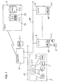
- Fig. 1 shows the configuration of a first embodiment of a biometric system of this invention
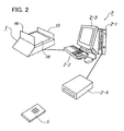
- Fig. 2 shows the configuration of the service area device of Fig. 1
- Fig. 3 is an external view of the automated transaction machine of Fig. 1
- Fig. 4 shows the configuration of the automated transaction machine of Fig. 3 .
- Fig. 1 shows a palm vein authentication system in a financial institution, as an example of a biometric system.
- a branch terminal 2 is provided in a service area of the financial institution. As explained in Fig. 2 , the branch terminal 2 is provided with a palm image capture device 1, a branch terminal computer (for example, a personal computer) 2-1 connected to the image capture device 1, a keyboard 2-2, a display 2-3, and an IC card reader/writer 2-4.
- the palm image capture device 1 may be configured integrally with the IC card reader/writer 2-4.
- the palm image capture device 1 has a sensor unit 18, front guide 14 to support the wrist of the user, and a rear guide 13 to guide the fingers of the user.
- the user having requested vein authentication, places his hand over this palm image capture device 1.
- the palm image capture device (hereafter “image capture device”) 1 reads the palm image, and sends the image to the computer 2-1.
- the IC card reader/writer 2-4 reads and writes data from and to an IC card 5 held by the user.
- the IC card 5 is a well-known credit card-size card, incorporating an IC chip with memory and a CPU, and having external terminals.
- the image capture device 1, IC card reader/writer 2-4, keyboard 2-2, and display 2-3 are connected to the computer 2-1, and perform the blood vessel image extraction, shape registration and other processing, described below.
- the terminal 2 is connected to a server 4 via a LAN (Local Area Network) 80.
- the server 4 has a temporary file 4-1, and is connected to the host 7.
- the server 4 is also connected to a plurality of automated transaction machines (ATMs) 6 via a second LAN 82.
- ATMs automated transaction machines
- Such an ATM 6 can be used to perform transactions based on vein authentication.
- the user holds his hand over the image capture device 1-1 provided in the ATM 6.
- the image capture device 1-1 reads an image of the palm.
- the ATM 6 has an IC card reader/writer 60, which reads and writes data in an IC card 5 held by the user.
- Fig. 3 and Fig. 4 show the configuration of the ATM 6 of Fig. 1 .
- the ATM 6 has, on the front face thereof, a card insertion/ejection aperture 6-4; a bankbook insertion/ejection aperture 6-5; a paper currency insertion/dispensing aperture 6-3; a coin insertion/dispensing aperture 6-2; and a customer operation panel (UOP) 6-1 for operation and display.
- UOP customer operation panel
- the image capture device 1-1 is provided on the side of the customer operation panel 6-1.
- the sensor unit 18 explained in Fig. 4 and Fig. 6 is mounted on the forward side of the main unit 10 of the image capture device 1-1. Further, the sensor unit 18 of the main unit 10 faces rearward and is inclined upward, and a flat portion 22 is provided therebehind.
- This image capture device 1-1 differs from the image capture device 1 of Fig. 2 in that the palm guides 14, 13 are not provided. This is because in registration, a single operation is sufficient, but in the case of a transaction based on authentication, dozens of operations are performed; hence in order to alleviate aversion of the user, guides 14, 13 are not provided in the image capture device 1-1 of the ATM 6. A further reason is that the existence of guides 14, 13 poses problems for operation by the user. Of course guides 14, 13 may be provided.
- the ATM 6 has a CIP (Card Reader Printer) unit 60 with a card insertion/ejection aperture 6-4; a bankbook unit 64 having a bankbook insertion/ejection aperture 6-5; a paper currency/coin counter unit 66 having a paper currency insertion/dispensing aperture 6-3 and a coin insertion/dispensing aperture 6-2; an attendant operation unit 65; a control unit 67; a customer operation panel (UOP) 6-1 for operation and display; and an image capture device (vein sensor) 1-1.
- CIP Card Reader Printer
- the CIP unit 60 has an IC card reader/writer 61 which reads and writes the magnetic stripe and IC chip of an IC card 5; a receipt printer 63 which records transactions on a receipt; and a journal printer 62 which prints the history of transactions on journal forms.
- the bankbook unit 64 records transactions on pages of a bankbook, and when necessary turns the pages.
- the attendant operation unit 65 is for operations by an attendant, who can display the state and perform operations upon occurrence of a fault or during inspections.
- the paper currency/coin counting unit 66 validates, counts, and stores inserted paper currency and coins, and counts and dispenses paper currency and coins in the required quantities.
- the control unit 67 communicates with the server 4, and has an ATM application 68 which controls ATM operation and an authentication library 69 for authentication processing. A portion of this ATM application 68 acts in concert with the authentication library 69 to control biometric authentication guidance screens of the UOP 6-1.
- a blood vessel (vein) image file 7-1 and customer database 7-2 are provided in the host 7.
- the blood vessel image file 7-1 stores vein data 70 and palm shape data 72 for users who have completed vein authentication registration.
- a user having requested vein authentication, holds his hand over the palm image capture device 1 of the service area terminal 2.
- the image capture device 1 reads the palm image and sends the image to the computer 2-1.
- the computer 2-1 extracts the blood vessel image for the palm, creates blood vessel image data 70, also creates hand outside shape data 72, and transfers to the server 4 the identification number (for example, account number) read from the IC card 5 as well as the blood vessel image data 70 and external shape data 72.
- the server 4 converts the transferred data into a prescribed format, and transfers the result to the host 7.
- the host 7 stores, in the blood vessel image file 7-1, the transferred identification number (for example, account number), blood vessel image data 70, and external shape data 72.
- the user inserts the IC card 5 into the IC card reader/writer 60 of the ATM 6, and causes data to be read.
- This data is transmitted to the host 7 via the LAN 82 and server 4.
- the host 7 searches the blood vessel image file 7-1, reads the blood vessel image data 70 and external shape data 72 corresponding to the transmitted identification number from the file 7-1, and transmits this data to the ATM 6 via the server 4 and LAN 82.
- this shape data is displayed on the UOP 6-1, reproducing the state of image capture for the user at the time of registration.
- the user can identify the state of image capture at the time of registration. Accordingly, the user places his hand in a similar manner over the image capture device 1-1 of the ATM 6.
- the image capture device 1-1 reads the image of the palm of the hand, and transmits the image to the control unit 67 of the ATM 6.
- the control unit 67 extracts the blood vessel image from the palm, creates blood vessel image data 70, verifies the data against the blood vessel image data transmitted from the host 7, and performs individual authentication. If the individual is confirmed satisfactorily, the ATM 6 then permits an ordinary automated transaction.
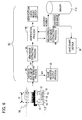
- Fig. 5 is a block diagram of biometric authentication processing at the service area terminal in Fig. 1 and Fig. 2
- Fig. 6 is a block diagram of biometric authentication processing by the ATM 6 in Fig. 1 , Fig. 3 , and Fig. 4
- Fig. 7 and Fig. 8 explain this operation.
- the palm image capture device 1 of Fig. 1 has a sensor unit 18 installed substantially in the center of the main unit 10.
- a front guide 14 On the forward portion (on the user side) of the sensor unit 18 is provided a front guide 14; on the rear side is provided a rear guide 13.
- the front guide 14 comprises a sheet of synthetic resin, transparent or substantially transparent.
- the front guide 14 serves the purposes of guiding the hand of the user in the front and of supporting the wrist; the rear guide 13 supports the tips of the fingers. Hence guidance and support are provided to the user, with the front guide 14 guiding the wrist above the sensor unit 18. As a result, the attitude of the palm of the hand, that is, the position, inclination, and size over the sensor unit 18 can be controlled.
- the cross-sectional shape of the front guide 14 has a vertical body and, in the top portion, a horizontal portion 14-1 to support the wrist.
- a depression 14-2 is formed continuously in the center of the horizontal portion 14-1, to facilitate positioning of the wrist.
- the sensor unit 18 is provided with a two-dimensional image capture sensor (infrared sensor) and focusing lens 16 and a distance sensor 15 in the center; on the periphery thereof are provided a plurality of near-infrared light emission elements (LEDs) 12.
- LEDs near-infrared light emission elements
- near-infrared light emission elements are provided at eight places on the periphery, to emit near-infrared rays upwards.
- the readable region V of this sensor unit 18 is regulated by the relation between the sensor, focusing lens, and near-infrared light emission region. Hence the position and height of the front guide 14 are set such that the supported palm is positioned in the readable region V.
- the authentication library of the computer 2-1 connected to the image capture device 1 executes a series of registration processing 30 to 36, 44 and 46.
- Distance/hand outline detection processing 30 receives the distance measured by the distance sensor 16 of the image capture devices 1, judges whether the palm of the hand or other object is at a distance in a prescribed range from the sensor unit 18, and also detects the outline of the hand from the image captured by the sensor unit 18 and judges from the outline whether the image can be used in registration and verification processing. For example, the palm may not appear sufficiently in the image.
- Guidance message output processing 32 outputs, to UOP 6-1 of the ATM 6, a message to guide the palm to the left or right, forward or backward, upward or downward, when the distance measured by the distance sensor 16 indicates that the hand is outside the image capture range, or when the image cannot be used in registration and verification processing. By this means, the palm of the hand of the user is guided into position over the image capture device 1.
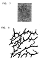
- Blood vessel image extraction processing 34 extracts a vein image from the image of the hand when hand outline detection processing 30 judges that an image has been captured with the hand held correctly. That is, blood vessel (vein) data 70 of the image of the palm such as that in Fig. 8 is extracted through differences in reflectivity. Fig. 8 shows the vein blood vessel image as an image, but the corresponding data is grayscale data of this image.
- Hand shape registration/output processing 36 stores in the storage portion (in Fig. 1 , the blood vessel image file 7-1 in the host 7), together with an account number, external shape data 72 for the hand (see Fig. 7 ) when an image is captured with the hand held correctly in hand outline detection processing 30.
- This hand shape data may be a bitmap of a captured image, as in Fig. 7 , or may be outline data of the hand, extracted from a captured image.
- Registered blood vessel image registration/search processing 46 stores blood vessel image data detected in the blood vessel image detection processing 34, together with the account number, in the storage portion (in Fig. 1 , in the blood vessel image file 7-1 of the host 7).
- the registered blood vessel image data sets R1, R2, R3 corresponding to the individual ID (account number) read from the IC card 5 indicated in Fig. 1 and Fig. 2 are retrieved from the storage portion 7-1.
- verification processing 44 the blood vessel image data N1 detected in blood vessel image detection processing 34 and registered blood vessel image data N2 are compared, verification processing is performed, and a verification result is output.
- the registered external shape data corresponding to the individual ID (account number) read from the IC card 5 of Fig. 1 and Fig. 2 is retrieved from the storage portion 7-1 and is displayed on the display 2-3.
- Fig. 6 is used to explain the biometric authentication mechanism of the ATM 6.
- the image capture device 1-1 of Fig. 1 and Fig. 3 has a sensor unit 18 installed substantially in the center of the main unit 10. As explained above, this image capture device 1-1 differs from the image capture device 1 of Fig. 5 in that a front guide 14 and rear guide 13 are not provided.
- the sensor unit 18 is provided with a two-dimensional image capture sensor (infrared sensor) and focusing lens 16 and a distance sensor 15 in the center; on the periphery thereof are provided a plurality of near-infrared light emission elements (LEDs) 12.
- LEDs near-infrared light emission elements
- near-infrared light emission elements are provided at eight places on the periphery, to emit near-infrared rays upwards.
- the readable region V of this sensor unit 18 is regulated by the relation between the sensor, focusing lens, and near-infrared light emission region.
- the authentication library 69 of the ATM 6 executes the series of verification processing 30 to 34, 38, 44, 46.
- the control unit 67 of the ATM 6 has, for example, a CPU and various types of memory, an interface circuit, and other circuitry necessary for data processing. This CPU executes the series of registration processing 30 to 34, 38, 44 and 46.
- Fig. 6 portions which are the same as in Fig. 5 are assigned the same symbols. That is, in Fig. 6 , the distance/outline detection processing 30, guidance message output processing 32, and blood vessel image extraction processing 34 are the same as in Fig. 5 .
- Registered blood vessel image search processing 46 retrieves registered blood vessel image data sets R1, R2, R3 corresponding to the individual ID (account number) of the IC card 5 from the storage portion 7-1. Verification processing 44 compares the blood vessel image data set N1 retrieved in blood vessel image detection processing 34 with the registered blood vessel image data set N2, performs verification processing, and outputs a verification result.
- Hand shape output processing 38 retrieves registration shape data 72 corresponding to the individual ID (account number) of the IC card 5 from the above-described storage portion 7-1, and displays the data on the UOP 6-1.
- the displayed image may be a bitmap of the image at the time of registration, as in Fig. 7 , or may be outline data of the hand, extracted from the captured image.
- the above-described captured image for use in authentication at the time of registration is registered, and the display of this image to the user at the time of authentication is convenient for the user, and is advantageous with respect to operation by users not familiar with the authentication system, and with respect to rapid authentication.
- FIG. 9 shows the flow of biometric registration processing in one embodiment of the invention. Below, the biometric registration processing of Fig. 9 is explained, referring to Fig. 2 and Fig. 5 .
- FIG. 10 shows the flow of biometric authentication processing in an embodiment of the invention.
- the biometric authentication processing of Fig. 10 is explained referring to Fig. 3 , Fig. 4 , and Fig. 6 .
- an image of the body part shape captured for the user at the time of registration of biometric data is registered, and at the time of user authentication, by displaying this body part shape, the user can directly identify the state of body part image capture at the time of registration.
- the user can be guided into a state of body part image capture similar to that at the time of registration, so that at the time of authentication effective guidance can be provided regarding positioning of the body part so as to match the circumstances of body part image capture during registration, to improve the efficiency of verification.
- biometric authentication even when biometric authentication is not successful, guidance can be provided to move the body part to the circumstances of body part image capture at the time of registration without causing the user to be confused, thus facilitating biometric authentication of the user.
- dedicated personnel may not be on site, but the user can be provided with reliable guidance, thus improving the efficiency of verification and contributing to shorten the time required for verification.
- FIG. 11 shows the flow of biometric authentication processing in another embodiment of the invention
- Fig. 12 explains the body part shape display example.
- the biometric authentication processing of Fig. 11 is explained referring to Fig. 3 , Fig. 4 , Fig. 6 , and Fig. 12 . Steps which are the same as in Fig. 10 are assigned the same symbols.
- the body part shape captured for the user at the time of registration of biometric data is registered, and at the time of user authentication, by displaying this body part shape and the body part shape during verification, the user can directly identify the state of body part image capture at the time of registration and the state of body part image capture at the time of verification.
- biometric authentication is unsuccessful, the user can be guided into a state of body part image capture similar to that at the time of registration, so that at the time of authentication effective guidance can be provided regarding positioning of the body part so as to match the circumstances of body part image capture during registration, to improve the efficiency of verification.
- guidance can be provided to move the body part to the circumstances of body part image capture at the time of registration without causing the user to be confused, thus facilitating biometric authentication of the user.
- dedicated personnel may not be on site, but the user can be provided with reliable guidance, thus improving the efficiency of verification and contributing to shorten the time required for verification.
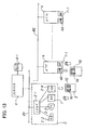
- Fig. 13 shows the configuration of the biometric system of a second embodiment of the invention.
- a palm vein authentication system in a financial institution is shown as an example of a biometric authentication system.
- portions which are the same as in Fig. 1 are assigned the same symbols.
- the branch terminal 2 explained in Fig. 2 is provided in a service area of the financial institution. As explained in Fig. 2 , the branch terminal 2 is provided with a palm image capture device 1, and, connected thereto, a branch terminal computer (for example, a personal computer) 2-1, keyboard 2-2, display 2-3, and IC card reader/writer 2-4.
- a branch terminal computer for example, a personal computer
- the palm image capture device 1 has a sensor unit 18, front guide 14 to support the wrist of the user, and a rear guide 13 to guide the fingers of the user.
- the user having requested vein authentication, places his hand over this palm image capture device 1.
- the image capture device (hereafter “image capture device”) 1 reads the palm image, and sends the image to the computer 2-1.
- the IC card reader/writer 2-4 reads and writes data from and to an IC card 5 held by the user.
- the IC card 5 is a well-known credit card-size card, incorporating an IC chip with memory and a CPU, and having external terminals.
- the image capture device 1, IC card reader/writer 2-4, keyboard 2-2, and display 2-3 are connected to the computer 2-1, and perform the blood vessel image extraction, shape registration and other processing, described above.
- This terminal 2 is connected, via a LAN (Local Area Network) 80, to the server 4.
- the server 4 has a temporary file 4-1, and is connected to a host (the host 7 of Fig. 1 ), not shown.
- the server 4 is connected, via a second LAN 82, to a plurality of automated transaction machines (ATMs) 6.
- ATMs automated transaction machines
- This ATM 6 can be used to perform transactions based on vein authentication.
- a user uses an ATM 6 to perform withdrawal or other cash transaction, he extends his hand over an image capture device 1-1, provided in the ATM 6.
- the image capture device 1-1 reads an image of the palm.
- the ATM 6 has an IC card reader/writer 60, and reads and writes the data from and onto the IC card 5 held by the user.
- the terminal 2 stores blood vessel characteristic data 70 and external shape data 72 in the IC card 5 of the user.
- the IC card reader/writer 60 reads the external shape data in the IC card 5 and displays the external shape on the UOP 6-1.
- the IC card 5 is provided with the functions for verification processing 44 and registered blood vessel image search processing 46 of Fig. 6 .
- Blood vessel image characteristic data at the time of verification read by the image capture device 1-1 of the ATM 6 and extracted, is transmitted to the IC card 5 via the IC card reader/writer 60.
- the IC card 5 verifies the registered blood vessel image characteristic data against verification blood vessel image characteristic data through the above-described verification processing 44 and registered blood vessel image search processing 46, and notifies the control unit 67 in the ATM 6 of the verification result.
- the registered blood vessel image data 70 remains held in the IC card 5, and is not read by the ATM 6, so that illicit replication and similar can be prevented, contributing to improved security.
- the external shape at the time of verification can also be displayed on the UOP 6-1 together with the external shape at the time of registration (registration shape). That is, as shown in Fig. 12 , the external shape of the hand at the time of verification (verification shape) is displayed together with the external shape of the hand at the time of registration (registration shape).
- Fig. 14 shows the configuration of a third embodiment of a biometric authorization system of this invention.
- Fig. 14 similarly to Fig. 1 and Fig. 13 , a palm vein authentication system in a financial institution is shown, as an example of a biometric system.
- Fig. 14 portions which are the same as in Fig. 1 and Fig. 13 are assigned the same symbols.
- a branch terminal 2 explained in Fig.2 is provided in a service area of the financial institution.
- the branch terminal 2 is provided with a palm image capture device 1, a branch terminal computer (for example, a personal computer) 2-1 connected to the image capture device 1, a keyboard 2-2, a display 2-3, and an IC card reader/writer 2-4.
- a branch terminal computer for example, a personal computer
- the palm image capture device 1 has a sensor unit 18, front guide 14 to support the wrist of the user, and a rear guide 13 to guide the fingers of the user.
- the user having requested vein authentication, places his hand over this palm image capture device 1.
- the image capture device (hereafter “image capture device”) 1 reads the palm image, and sends the image to the computer 2-1.
- the IC card reader/writer 2-4 reads and writes data from and to an IC card 5 held by the user.
- the IC card 5 is a well-known credit card-size card, incorporating an IC chip with memory and a CPU, and having external terminals.
- the image capture device 1, IC card reader/writer 2-4, keyboard 2-2, and display 2-3 are connected to the computer 2-1, and perform the blood vessel image extraction, shape registration and other processing, described above.
- the terminal 2 is connected to a server 4 via a LAN (Local Area Network) 80.
- the server 4 has a temporary file 4-1, and is connected to the host 7.
- the server 4 is also connected to a plurality of automated transaction machines (ATMs) 6 via a second LAN 82.
- ATMs automated transaction machines
- Such an ATM 6 can be used to perform transactions based on vein authentication.
- the user holds his hand over the image capture device 1-1 provided in the ATM 6.
- the image capture device 1-1 reads an image of the palm.
- the ATM 6 has an IC card reader/writer 60, which reads and writes data in an IC card 5 held by the user.
- the terminal 2 stores blood vessel image characteristic data 70 in the IC card 5 of the user, and stores external shape data 72 in the vein database 7-1 of the host 7.
- the IC card 5 of the user is inserted into the IC card reader/writer 60, an identification number is read, external shape data is read from the vein database 7-1 of the host 7 via the server 4, and the external shape is displayed on the UOP 6-1.
- the IC card 5 is provided with the functions for verification processing 44 and registered blood vessel image search processing 46 of Fig. 6 .
- Blood vessel image characteristic data at the time of verification which is read and extracted by the image capture device 1-1 of the ATM 6, is transmitted to the IC card 5 via the IC card reader/writer 60.
- the IC card 5 verifies the registered blood vessel image characteristic data against the verification blood vessel image characteristic data, and notifies the control unit 67 of the ATM 6 of the verification result.
- the registered blood vessel image data 70 remains held in the IC card 5, and is not read by the ATM 6, so that illicit reproduction can be prevented, contributing to improved security.
- the external shape at the time of verification can also be displayed on the UOP 6-1. That is, as shown in Fig. 12 , the external shape of the hand at the time of registration (registration shape) is combined with the external shape of the hand at the time of verification (verification shape) and displayed.
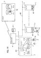
- Fig. 15 shows the configuration of the biometric authentication system of a fourth embodiment of the invention.
- a palm vein authentication system in a financial institution is shown as an example of a biometric authentication system.
- portions which are the same as in Fig. 1 , Fig. 13 , and Fig. 14 are assigned the same symbols.
- the branch terminal 2 explained in Fig. 2 is provided in a service area of the financial institution. As explained in Fig. 2 , the branch terminal 2 is provided with a palm image capture device 1, and, connected thereto, a branch terminal computer (for example, a personal computer) 2-1, keyboard 2-2, display 2-3, and IC card reader/writer 2-4.
- a branch terminal computer for example, a personal computer
- the palm image capture device 1 has a sensor unit 18, front guide 14 to support the wrist of the user, and a rear guide 13 to guide the fingers of the user.
- the user having requested vein authentication, places his hand over this palm image capture device 1.
- the image capture device (hereafter “image capture device”) 1 reads the palm image, and sends the image to the computer 2-1.
- the IC card reader/writer 2-4 reads and writes data from and to an IC card 5 held by the user.
- the IC card 5 is a well-known credit card-size card, incorporating an IC chip with memory and a CPU, and having external terminals.
- the image capture device 1, IC card reader/writer 2-4, keyboard 2-2, and display 2-3 are connected to the computer 2-1, and perform the blood vessel image extraction, shape registration and other processing, described above.
- the terminal 2 is connected to a server 4 via a LAN (Local Area Network) 80.
- the server 4 has a temporary file 4-1, and is connected to the host 7.
- the server 4 is also connected to a plurality of automated transaction machines (ATMs) 6 via a second LAN 82.
- ATMs automated transaction machines
- Such an ATM 6 can be used to perform transactions based on vein authentication.
- the user holds his hand over the image capture device 1-1 provided in the ATM 6.
- the image capture device 1-1 reads an image of the palm.
- the ATM 6 has an IC card reader/writer 60, which reads and writes data in an IC card 5 held by the user.
- a telephone set 6-6 for telephone communication via a call center 8 and public circuit network 9 is provided in the ATM 6.
- a terminal 80 connected to the host 7 is provided in the call center 8.
- the terminal 2 stores blood vessel image characteristic data 70 in the IC card 5 of the user, and stores external shape data 72 in the vein database 7-1 of the host 7.
- the user inserts the IC card 5 into the IC card reader/writer 60, the identification number is read, and the host 7 is notified of the identification number via the server 4.
- the host 7 reads the external shape data from the vein database 7-1, and displays the external shape on the display of the terminal 80 at the call center 8.
- the IC card 5 is provided with the functions for verification processing 44 and registered blood vessel image search processing 46 of Fig. 6 .
- Blood vessel image characteristic data at the time of verification which is read and extracted by the image capture device 1-1 of the ATM 6, is transmitted to the IC card 5 via the IC card reader/writer 60.
- the IC card 5 verifies the registered blood vessel image characteristic data against the verification blood vessel image characteristic data, and notifies the control unit 67 of the ATM 6 of the verification result.
- the user calls the dedicated personnel at the call center 8 from the telephone set 6-6 via the public circuit network 9, and queries the cause of the verification failure.
- the dedicated personnel at the call center 8 views the registered external shape on the terminal 80 and responds to the user. This dedicated personnel is thoroughly acquainted with the causes of verification failure, and so upon viewing the registered external shape, can provide appropriate guidance and instructions to the user.
- a registered external shape of the hand can be viewed, and portions in which the state of image capture is different at the time of verification can be noted. That is, instructions can be given regarding that the distance between the hand and the image capture device 1-1, the spreading of the fingers, drooping of the fingers, and the positions of fingers relative to the image capture device are different from the image capture state at the time of registration.
- the user can obey the instructions of the dedicated personnel, altering the state of image capture, and can obtain a satisfactory verification result.
- the registered blood vessel image data 70 remains held in the IC card 5, and is not read by the ATM 6, so that illicit reproduction can be prevented, contributing to improved security.
- the external shape at the time of verification is transmitted to the terminal 80 of the call center 8 from the ATM 6, via the server 4 and host 7.
- the external shape at the time of verification (verification shape) can be displayed, together with the external shape at the time of registration (registration shape), on the display of the terminal 80 of the call center 8. That is, as shown in Fig. 12 , the external shape of the hand at the time of verification (verification shape) is displayed together with the external shape of the hand at the time of registration (registration shape).
- the dedicated personnel can view the external shape at the time of registration (registration shape) and the external shape at the time of verification (verification shape), and can provide appropriate guidance and instruction.
- verification is performed within the IC card 5, contributing to improved security; moreover, because external shapes are not used directly in biometric authentication, degradation of security can be prevented even when such shapes are stored on the host 7, and the burden on the IC card 5 can be alleviated.
- contact-free biometric authentication was explained in terms of palm vein pattern authentication; however, application to authentication of vein patterns in the back of the hand or the fingers, as well as to palmprints or other characteristics of the hand, and to fingerprints, facial features, and authentication using other body parts, is also possible. Further, the biometric authentication system was explained as applied to automated equipment in financial businesses; but application to automated ticket issuing machines, automated vending machines, and other automated equipment in various fields, as well as to computers and to door opening/closing and other tasks involving replacement of a key which require individual authentication, is also possible.
- the media held by the user is not limited to IC cards, but may be portable telephones or other portable equipment. Further, application to biometric authentication systems not employing media is also possible. Further, display of the registration shape and verification shape in Fig. 11 and Fig. 12 is not limited to lateral arrangement; vertical arrangement is possible, and overlapping display is also possible.
- the user can directly identify the state of body part image capture at the time of registration.
- the user can be guided into a state of body part image capture similar to that at the time of registration, so that verification efficiency is improved.
- the body part can be guided into the circumstances of image capture at the time of registration without causing confusion on the part of the user, thus adding to the convenience to the user in biometric authentication.
- dedicated personnel may not be on site, but the user can be provided with reliable guidance, thus improving the efficiency of verification and contributing to shorten the time required for verification.
Landscapes
- Engineering & Computer Science (AREA)
- Physics & Mathematics (AREA)
- General Physics & Mathematics (AREA)
- Theoretical Computer Science (AREA)
- Multimedia (AREA)
- Human Computer Interaction (AREA)
- Bioinformatics & Cheminformatics (AREA)
- Artificial Intelligence (AREA)
- Life Sciences & Earth Sciences (AREA)
- Bioinformatics & Computational Biology (AREA)
- Computer Vision & Pattern Recognition (AREA)
- Data Mining & Analysis (AREA)
- Evolutionary Biology (AREA)
- Evolutionary Computation (AREA)
- General Engineering & Computer Science (AREA)
- Collating Specific Patterns (AREA)
- Measurement Of The Respiration, Hearing Ability, Form, And Blood Characteristics Of Living Organisms (AREA)
Claims (16)
- Biometrisches System, das charakteristische Daten eines Körperteils, die in einer Speichereinheit (5, 7-1) registriert sind, gegenüber charakteristischen Daten des Körperteils verifiziert, die durch Bilderfassung erhalten wurden, um eine Authentisierung einer Person auszuführen, mit:einer Bilderfassungsvorrichtung (1, 1-1), die Bilder des Körperteils erfasst;einer Steuervorrichtung (2, 4, 67), die charakteristische Daten des Körperteils aus dem erfassten Bild des Körperteils extrahiert und die extrahierten charakteristischen Daten gegenüber den registrierten charakteristischen Daten verifiziert, um eine Authentisierung einer Person auszuführen;einer Anzeigevorrichtung (2-3, 6-1, 80), die, zu der Zeit der Authentisierung der Person, eine Form des Körperteils anzeigt, die von der Bilderfassung zu der Zeit der Registrierung der charakteristischen Daten des Körperteils erhalten wurde, die in der Speichereinheit (5, 7-1) gespeichert sind, undeiner Eingabeeinheit (2-4, 60), zum Eingeben einer Identifikationsnummer, um von der Speichereinheit (5, 7-1) Formdaten des Körperteils des Nutzers abzurufen, für den die Authentisierung der Person auszuführen ist,bei dem die Speichereinheit (5, 7-1), zu der Zeit der Registrierung der charakteristischen Daten des Körperteils, Formdaten des Körperteils, die bei der Bilderfassung des Körperteils erhalten wurden, und charakteristische Daten des Körperteils speichert, die Steuervorrichtung (2, 4, 67), zu der Zeit der biometrischen Authentisierung, die Formdaten des Körperteils und die charakteristischen Daten des Körperteils von der Speichereinheit (5, 7-1) liest unddie Steuervorrichtung (2, 4, 67) an der Anzeigevorrichtung (2-3, 6-1, 80) eine Form des Körperteils zu der Zeit der Verifizierung, die bei der Bilderfassung durch die Bilderfassungsvorrichtung (1, 1-1) erhalten wurde, zusammen mit der Form des Körperteils zu der Zeit der Registrierung anzeigt, wobei der betreffende Körperteil die Hand des Nutzers ist,dadurch gekennzeichnet, dass die Bilderfassungsvorrichtung (1, 1-1) eine Bilderfassungseinheit umfasst, die Bilder von wenigstens einem Abschnitt einer Hand eines Nutzers erfasst,und die Steuervorrichtung (2, 4, 67) Blutgefäßbilddaten des Abschnittes der Hand aus dem erfassten Bild extrahiert und an der Anzeigevorrichtung (2-3, 6-1, 80) eine Form der Hand desselben Nutzers zu der Zeit der Verifizierung, die bei der Bilderfassung durch die Dilderfassungsvorrichtung (1, 1-1) erhalten wurde, neben und parallel zu der Form der Hand zu der Zeit der Registrierung anzeigt.
- Biometrisches System nach Anspruch 1, ferner mit einer Vorrichtung zur Registrierung biometrische Daten (1, 2), die ein Bild des Körperteils erfasst, Formdaten des Körperteils und charakteristische Daten des Körperteiles aus dem erfassten Bild extrahiert und die Daten in der Speichereinheit (5, 7-1) speichert.
- Biometrisches System nach Anspruch 1, bei dem die Eingabeeinheit eine tragbare Einheit ist, die der Nutzer besitzt.
- Biometrisches System nach einem vorhergehenden Anspruch, bei dem die Speichereinheit (7-1) in einer übergeordneten Vorrichtung (7) vorgesehen ist, die mit der Steuervorrichtung (2, 4, 67) verbunden ist.
- Biometrisches System nach einem der Ansprüche 1 bis 3, bei dem die Speichereinheit (5) in einer tragbaren Einheit vorgesehen ist, die der Nutzer besitzt.
- Biometrisches System nach einem der Ansprüche 1 bis 3, bei dem die Speichereinheit (5, 7-1) umfasst:eine übergeordnete Vorrichtung (7), die mit der Steuervorrichtung (2, 4, 67) verbunden ist und Formdaten des Körperteils speichert; undeine tragbare Einheit, die der Nutzer besitzt und die charakteristische Daten des Körperteils speichert.
- Biometrisches System nach Anspruch 1, ferner mit:einer Kommunikationseinheit (6-6), durch die, zu der Zeit der Authentisierung der Person, der Nutzer eine Anrufzentrale anruft; und bei demdie Anzeigeeinheit eine Terminalvorrichtung (80) umfasst, die die Form des Körperteils des Nutzers von der Speichereinheit (7-1) liest und die Form der Hand zu der Zeit der Verifizierung neben und parallel zu der Form der Hand zu der Zeit der Registrierung an der Anzeigevorrichtung in der Anrufzentrale anzeigt, zum Ermöglichen einer Führung, die für den Nutzer von der Anrufzentrale vorzusehen ist.
- Biometrisches System nach Anspruch 5 oder Anspruch 6, bei dem die tragbare Einheit die charakteristischen Daten des Körperteils, die aus dem erfassten Bild des Körperteils extrahiert wurden, gegenüber den charakteristischen Daten, die in der Speichereinheit (5, 7-1) registriert sind, verifiziert und eine Authentisierung der Person ausführt.
- Biometrisches Verfahren zum Verifizieren von charakteristischen Daten eines Körperteils, die in einer Speichereinheit (5, 7-1) registriert sind, gegenüber charakteristischen Daten des Körperteils, die durch Bilderfassung erhalten wurden, um eine Authcntisierung einer Person auszuführen, mit:einem Bilderfassungsschritt zum Erfassen eines Bildes des Körperteils auf kontaktfreie Weise durch eine Bilderfassungsvorrichtung (1, 1-1);einem Schritt zum Extrahieren von charakteristischen Daten des Körperteils aus dem erfassten Bild des Körperteils;einem Schritt zum Speichern, in der Speichereinheit (5, 7-1), zu der zeit der Registrierung der charakteristischen Daten des Körperteils, von Formdaten des Körperteils und von charakteristischen Daten des Körperteils, dic bei der Dilderfassung des Körperteils erhalten wurden;einem Eingabeschritt zum Eingeben einer Identifikaticonsnummer, um von der Speichereinheit (5, 7-1) Formdaten des Körperteils des Nutzers abzurufen, für den die Authentisierung der Person auszuführen ist, einem Schritt zum Lesen, zu der Zeit der biometrischen Authentisierung, der Formaten des Körperteils und der charakteristischen Daten des Körperteils von der Speichereinheit (5, 7-1);einem Authentisierungsschritt zum Verifizieren der extrahierten charakteristischen Daten des Körperteils gegenüber den registrierten charakteristischen Daten; undeinem Anzeigeschritt, zu der Zeit der Authentisierung der Person, zum Anzeigen an einer Anzeigevorrichtung (2-3, 6-1, 80) einer Form des Körperteils, die durch Bilderfassung durch die Bilderfassungsvorrichtung (1, 1-1) zu der Zeit der Verifizierung erhalten wurde, zusammen mit der Form des Körperteils zu der Zeit der Registrierung, wobei der betreffende Körperteil die Hand des Nutzers ist,dadurch gekennzeichnet, dass der Bilderfassungsschritt einen Bilderfassungsschritt zum Erfassen eines Bildes von wenigstens einem Abschnitt der Hand des Nutzers umfasst,der Authentisierungsschritt einen Schritt zum Extrahieren von Dlutgefäßbilddaten der Hand aus dem erfassten Bild umfasst undder Anzeigeschritt einen Schritt zum Anzeigen, an der Anzeigevorrichtung (2-3, 6-1, 80), einer Form der Hand desselben Nutzers zu der Zeit der Verifizierung, die durch Bilderfassung durch die Bilderfassungsvorrichtung (1, 1-1) erhalten wurde, neben und parallel zu der Form der Hand zu der Zeit der Registrierung umfasst.
- Biometrisches Verfahren nach Anspruch 9, ferner mit einem Registrierungsschritt zum erfassen eines Bildes des Körperteils, Extrahieren von Formdaten des Körperteils und charakteristischen Daten des Körperteils aus dem erfassten Bild und Speichern der Daten in der Speichereinheit.
- Biometrisches Verfahren nach Anspruch 9, bei dem der Eingabeschritt einen Schritt umfasst zum Eingeben von einer tragbaren Einheit, die der Nutzer besitzt.
- Biometrisches Verfahren nach einem der Ansprüche 9 bis 11, bei dem der Authentisierungsschritt einen Schritt umfasst zum Lesen, von der Speichereinheit, die in einer übergeordneten Vorrichtung vorgesehen ist, die mit einer Steuervorrichtung verbunden ist, die die Authentisierung ausführt, der Formdaten des Körperteils und der charakteristischen Daten des Körperteils zu der Zeit der Registrierung.
- Biometrisches Verfahren nach einem der Ansprüche 9 bis 11, bei dem der Authentisierungsschritt einen Schritt umfasst zum Lesen, von der Speichereinheit, die in einer tragbaren Einheit vorgesehen ist, die der Nutzer besitzt, der Formdaten des Körperteils und der charakteristischen Daten des Körperteils zu der Zeit der Registrierung.
- Biometrisches Verfahren nach einem der Ansprüche 9 bis 11, bei dem der Anzeigeschritt einen Schritt umfasst zum Lesen der Formdaten des Körperteils von einer übergeordneten Vorrichtung, die mit einer Steuervorrichtung verbunden ist, die die Authentisierung ausführt,
und bei dem der Authentisierungsschritt einen Schritt umfasst zum Lesen der charakteristischen Daten des Körperteils von einer tragbaren Einheit, die der Nutzer besitzt. - Biometrisches Verfahren nach Anspruch 9, ferner mit:einem Schritt, bei dem der Nutzer eine Anrufzentrale von einer Kommunikationsvorrichtung zu der Zeit der Authentisierung der Person anruft; undeinem Schritt zum Lesen der Formdaten des Körperteils des Nutzers von der Speichereinheit, Anzeigen der Form der Hand zu der Zeit der Verifizierung neben und parallel zu der Form der Hand zu der Zeit der Registrierung an einer Anzeigeeinheit (80) in der Anrufzentrale und Vorsehen einer Führung für den Nutzer.
- Biometrisches Verfahren nach Anspruch 12, bei dem der Authentisierungsschritt einen Schritt umfasst zum Verifizieren, durch die tragbare Einheit, der charakteristischen Daten des Körperteils, die aus dem erfassten Körpertcilbild extrahiert wurden, gegenüber den registrierten charakteristischen Daten in der Speichereinheit, um eine Authentisierung der Person auszuführen.
Applications Claiming Priority (1)
| Application Number | Priority Date | Filing Date | Title |
|---|---|---|---|
| JP2005313092A JP4704185B2 (ja) | 2005-10-27 | 2005-10-27 | 生体認証システム及び生体認証方法 |
Publications (3)
| Publication Number | Publication Date |
|---|---|
| EP1780657A2 EP1780657A2 (de) | 2007-05-02 |
| EP1780657A3 EP1780657A3 (de) | 2007-08-15 |
| EP1780657B1 true EP1780657B1 (de) | 2009-11-04 |
Family
ID=37696099
Family Applications (1)
| Application Number | Title | Priority Date | Filing Date |
|---|---|---|---|
| EP06252422A Expired - Fee Related EP1780657B1 (de) | 2005-10-27 | 2006-05-08 | Biometrisches System und biometrisches Verfahren |
Country Status (7)
| Country | Link |
|---|---|
| US (1) | US7742626B2 (de) |
| EP (1) | EP1780657B1 (de) |
| JP (1) | JP4704185B2 (de) |
| KR (1) | KR100823755B1 (de) |
| CN (1) | CN100522058C (de) |
| DE (1) | DE602006010154D1 (de) |
| ES (1) | ES2334157T3 (de) |
Cited By (2)
| Publication number | Priority date | Publication date | Assignee | Title |
|---|---|---|---|---|
| CN106203367A (zh) * | 2016-07-18 | 2016-12-07 | 北京红马传媒文化发展有限公司 | 一种身份识别的方法、系统及终端 |
| US20220301354A1 (en) * | 2012-11-14 | 2022-09-22 | Golan Weiss | Methods and systems for enrollment and authentication |
Families Citing this family (42)
| Publication number | Priority date | Publication date | Assignee | Title |
|---|---|---|---|---|
| US8320645B2 (en) * | 2004-11-02 | 2012-11-27 | Identix Incorporated | High performance multi-mode palmprint and fingerprint scanning device and system |
| CN101460972A (zh) * | 2006-06-08 | 2009-06-17 | 富士通株式会社 | 引导装置及方法 |
| US9042606B2 (en) * | 2006-06-16 | 2015-05-26 | Board Of Regents Of The Nevada System Of Higher Education | Hand-based biometric analysis |
| JP4680158B2 (ja) * | 2006-09-13 | 2011-05-11 | 株式会社日立製作所 | 生体認証装置 |
| JP4786483B2 (ja) * | 2006-09-14 | 2011-10-05 | 富士通株式会社 | 生体認証装置の生体誘導制御方法及び生体認証装置 |
| US20080085046A1 (en) * | 2006-10-04 | 2008-04-10 | Yen-Chieh Lee | Detailed identification method for articles |
| JP5293950B2 (ja) * | 2008-03-04 | 2013-09-18 | 株式会社リコー | 個人認証装置及び電子機器 |
| JP4541427B2 (ja) | 2008-03-25 | 2010-09-08 | 富士通株式会社 | 生体認証装置、生体情報登録装置および生体認証方法 |
| CN101571902B (zh) * | 2008-04-29 | 2011-09-14 | 慧国(上海)软件科技有限公司 | 使用网络摄影机保护数字数据的方法及电脑系统 |
| ES2329328B1 (es) | 2008-05-23 | 2010-08-30 | Hanscan Ip B.V. | Procedimiento y escaner biometrico para identificar a una persona. |
| ES2345598B8 (es) | 2009-03-24 | 2013-02-12 | Hanscan Ip B.V. | Escaner biometrico tridimensional |
| US8655084B2 (en) * | 2009-06-23 | 2014-02-18 | Board Of Regents Of The Nevada System Of Higher Education, On Behalf Of The University Of Nevada, Reno | Hand-based gender classification |
| US8659390B2 (en) * | 2009-08-04 | 2014-02-25 | Raytheon Company | Method and system for generating a biometric query plan |
| US20110087611A1 (en) * | 2009-10-14 | 2011-04-14 | Shyam Chetal | Biometric identification and authentication system for financial accounts |
| JP5399862B2 (ja) * | 2009-10-30 | 2014-01-29 | 富士通フロンテック株式会社 | 姿勢情報付き生体情報による個人認証・操作指示入力方法、装置、及びプログラム |
| US8532343B1 (en) * | 2010-04-16 | 2013-09-10 | Steven Jay Freedman | System for non-repudiable registration of an online identity |
| WO2012014304A1 (ja) * | 2010-07-29 | 2012-02-02 | 富士通株式会社 | 生体認証装置および生体認証プログラム |
| CA2822502A1 (en) * | 2010-10-11 | 2012-06-14 | Woundmatrix, Inc. | Wound management mobile image capture device |
| CN102063740A (zh) * | 2010-11-15 | 2011-05-18 | 北京交通大学 | 基于手掌静脉网络特征认证的实名制火车票检票系统 |
| JP5794410B2 (ja) * | 2010-12-20 | 2015-10-14 | 日本電気株式会社 | 認証カード、認証システム、ガイダンス方法及びプログラム |
| US8548206B2 (en) | 2011-01-20 | 2013-10-01 | Daon Holdings Limited | Methods and systems for capturing biometric data |
| US8457370B2 (en) | 2011-01-20 | 2013-06-04 | Daon Holdings Limited | Methods and systems for authenticating users with captured palm biometric data |
| JP5810581B2 (ja) | 2011-03-29 | 2015-11-11 | 富士通株式会社 | 生体情報処理装置、生体情報処理方法、および生体情報処理プログラム |
| RU2475185C1 (ru) * | 2011-08-10 | 2013-02-20 | Общество С Ограниченной Ответственностью "Абилма" | Система регистрации папиллярных узоров |
| CN102663355A (zh) * | 2012-03-27 | 2012-09-12 | 天津理工大学 | 基于手背静脉与手形结合的识别系统与方法 |
| US10140537B2 (en) * | 2012-10-26 | 2018-11-27 | Daon Holdings Limited | Methods and systems for capturing biometric data |
| GB2525516B (en) * | 2012-11-14 | 2020-04-22 | Weiss Golan | Biometric methods and systems for enrollment and authentication |
| JP6160148B2 (ja) * | 2013-03-19 | 2017-07-12 | 富士通株式会社 | 生体情報入力装置、生体情報入力プログラム、生体情報入力方法 |
| WO2015002608A1 (en) * | 2013-07-05 | 2015-01-08 | Dbs Bank Ltd | System and method for providing bank transactions with a remote bank device |
| CN104298941B (zh) * | 2013-07-19 | 2019-06-18 | 鸿富锦精密工业(深圳)有限公司 | 手持设备、信息输入方法及信息输入系统 |
| CN103997504B (zh) * | 2014-06-13 | 2017-11-10 | 谭知微 | 身份验证系统及身份验证方法 |
| JP2016081071A (ja) * | 2014-10-09 | 2016-05-16 | 富士通株式会社 | 生体認証装置、生体認証方法及びプログラム |
| US11961105B2 (en) * | 2014-10-24 | 2024-04-16 | Ganart Technologies, Inc. | Method and system of accretive value store loyalty card program |
| KR20160090047A (ko) * | 2015-01-21 | 2016-07-29 | 현대자동차주식회사 | 차량, 차량의 제어 방법 및 차량에 포함되는 동작 인식 장치 |
| US10706266B2 (en) * | 2015-09-09 | 2020-07-07 | Nec Corporation | Guidance acquisition device, guidance acquisition method, and program |
| JP6559024B2 (ja) | 2015-09-10 | 2019-08-14 | ローレルバンクマシン株式会社 | 機器セキュリティ管理装置、金融処理システム、機器セキュリティ管理方法及びプログラム |
| US20170091521A1 (en) * | 2015-09-30 | 2017-03-30 | Synaptics Incorporated | Secure visual feedback for fingerprint sensing |
| JP6706485B2 (ja) * | 2015-11-13 | 2020-06-10 | 東京電力ホールディングス株式会社 | 集中制御システム |
| US10963159B2 (en) * | 2016-01-26 | 2021-03-30 | Lenovo (Singapore) Pte. Ltd. | Virtual interface offset |
| JP2017162301A (ja) * | 2016-03-10 | 2017-09-14 | 富士通株式会社 | 生体認証装置、生体認証方法および生体認証プログラム |
| JP6988523B2 (ja) * | 2018-01-30 | 2022-01-05 | 富士通株式会社 | 生体認証装置、生体認証プログラム、及び生体認証方法 |
| CN109618100B (zh) * | 2019-01-15 | 2020-11-27 | 北京旷视科技有限公司 | 现场拍摄图像的判断方法、装置及系统 |
Family Cites Families (22)
| Publication number | Priority date | Publication date | Assignee | Title |
|---|---|---|---|---|
| US4792226A (en) | 1987-02-27 | 1988-12-20 | C.F.A. Technologies, Inc. | Optical fingerprinting system |
| US5054090A (en) * | 1990-07-20 | 1991-10-01 | Knight Arnold W | Fingerprint correlation system with parallel FIFO processor |
| JPH0721373A (ja) | 1993-06-17 | 1995-01-24 | Asahi Optical Co Ltd | 個人識別装置 |
| US6560352B2 (en) * | 1999-10-08 | 2003-05-06 | Lumidigm, Inc. | Apparatus and method of biometric identification or verification of individuals using optical spectroscopy |
| JP3434756B2 (ja) | 1999-12-07 | 2003-08-11 | エヌイーシ−カスタムテクニカ株式会社 | 指紋認証方法及び装置 |
| JP3825222B2 (ja) | 2000-03-24 | 2006-09-27 | 松下電器産業株式会社 | 本人認証装置および本人認証システムならびに電子決済システム |
| JP2001273948A (ja) | 2000-03-27 | 2001-10-05 | Honda Tsushin Kogyo Co Ltd | カード用コネクタ装置 |
| KR20010016241A (ko) * | 2000-11-27 | 2001-03-05 | 김재희 | 자동 눈 영상 획득방법 |
| GB2372131A (en) | 2001-02-10 | 2002-08-14 | Hewlett Packard Co | Face recognition and information system |
| KR100430268B1 (ko) * | 2001-03-15 | 2004-05-04 | 엘지전자 주식회사 | 홍채 인식 시스템의 촛점 각도 표시장치 |
| US6758394B2 (en) | 2001-07-09 | 2004-07-06 | Infonox On The Web | Identity verification and enrollment system for self-service devices |
| JP3974375B2 (ja) * | 2001-10-31 | 2007-09-12 | 株式会社東芝 | 人物認識装置、人物認識方法および通行制御装置 |
| EP1385116A1 (de) | 2002-07-22 | 2004-01-28 | Human Bios GmbH | Verfahren zur Erteilung einer Zugangsberechtigung |
| JP4387643B2 (ja) | 2002-07-31 | 2009-12-16 | 富士通株式会社 | 個人認識機能付き処理装置 |
| JP3810782B2 (ja) | 2002-09-03 | 2006-08-16 | 富士通株式会社 | 個人認識装置 |
| US8190239B2 (en) * | 2002-09-03 | 2012-05-29 | Fujitsu Limited | Individual identification device |
| KR100547333B1 (ko) * | 2003-03-17 | 2006-01-26 | 엘지전자 주식회사 | 홍채 시스템의 거리 표시 방법 |
| JP4207717B2 (ja) | 2003-08-26 | 2009-01-14 | 株式会社日立製作所 | 個人認証装置 |
| JP2005078589A (ja) * | 2003-09-03 | 2005-03-24 | Toshiba Corp | 人物認識装置および通行制御装置 |
| JP2005208863A (ja) * | 2004-01-21 | 2005-08-04 | Oki Electric Ind Co Ltd | 媒体発行システム |
| JP4515850B2 (ja) * | 2004-07-30 | 2010-08-04 | 富士通株式会社 | 生体認証装置の誘導画面制御方法、生体認証装置及びそのプログラム |
| JP2006268493A (ja) | 2005-03-24 | 2006-10-05 | Canon Inc | 画像処理装置、画像処理方法プログラム及び記憶媒体 |
-
2005
- 2005-10-27 JP JP2005313092A patent/JP4704185B2/ja not_active Expired - Fee Related
-
2006
- 2006-05-05 US US11/418,368 patent/US7742626B2/en not_active Expired - Fee Related
- 2006-05-08 DE DE602006010154T patent/DE602006010154D1/de active Active
- 2006-05-08 EP EP06252422A patent/EP1780657B1/de not_active Expired - Fee Related
- 2006-05-08 ES ES06252422T patent/ES2334157T3/es active Active
- 2006-05-30 KR KR1020060048771A patent/KR100823755B1/ko not_active IP Right Cessation
- 2006-06-02 CN CNB2006100885551A patent/CN100522058C/zh not_active Expired - Fee Related
Cited By (3)
| Publication number | Priority date | Publication date | Assignee | Title |
|---|---|---|---|---|
| US20220301354A1 (en) * | 2012-11-14 | 2022-09-22 | Golan Weiss | Methods and systems for enrollment and authentication |
| US11823499B2 (en) * | 2012-11-14 | 2023-11-21 | Golan Weiss | Methods and systems for enrollment and authentication |
| CN106203367A (zh) * | 2016-07-18 | 2016-12-07 | 北京红马传媒文化发展有限公司 | 一种身份识别的方法、系统及终端 |
Also Published As
| Publication number | Publication date |
|---|---|
| CN1954775A (zh) | 2007-05-02 |
| KR100823755B1 (ko) | 2008-04-21 |
| JP2007122368A (ja) | 2007-05-17 |
| US20070098223A1 (en) | 2007-05-03 |
| EP1780657A3 (de) | 2007-08-15 |
| CN100522058C (zh) | 2009-08-05 |
| ES2334157T3 (es) | 2010-03-05 |
| KR20070045897A (ko) | 2007-05-02 |
| JP4704185B2 (ja) | 2011-06-15 |
| EP1780657A2 (de) | 2007-05-02 |
| DE602006010154D1 (de) | 2009-12-17 |
| US7742626B2 (en) | 2010-06-22 |
Similar Documents
| Publication | Publication Date | Title |
|---|---|---|
| EP1780657B1 (de) | Biometrisches System und biometrisches Verfahren | |
| US7697730B2 (en) | Guidance screen control method of biometrics authentication device, biometrics authentication device, and program for same | |
| US7471810B2 (en) | Renewal method and renewal apparatus for an IC card having biometrics authentication functions | |
| US7729518B2 (en) | Biometrics authentication method biometrics authentication device and blood vessel image reading device | |
| US7508958B2 (en) | IC card access control method for biometrics authentication, biometrics authentication method, and biometrics authentication device | |
| US8972741B2 (en) | Method of modification of authorization details for a biometrics authentication device, biometrics authentication method, and biometrics authentication device | |
| US20060143117A1 (en) | Automated transaction control method, automated transaction device, and storage medium stored program for same | |
| EP1646013A2 (de) | Verfahren, Vorrichtung und Programm zur individuellen Beglaubigung | |
| US20060130138A1 (en) | Automated transaction control method, automated transaction device, and storage medium stored program for same | |
| US7508957B2 (en) | Method of registration of authorized agent information for a biometrics authentication device, authentication method for a biometrics authentication device, and biometrics authentication device | |
| EP1612716B1 (de) | Benutzerschnittstelle zur Bildeingabe in einem biometrischen Authentifikationsgerät; entsprechendes Gerät, Verfahren und Programm | |
| EP1612714A2 (de) | Biometrische Authentisierung mit Übertragung von verschlüsselten Daten |
Legal Events
| Date | Code | Title | Description |
|---|---|---|---|
| PUAI | Public reference made under article 153(3) epc to a published international application that has entered the european phase |
Free format text: ORIGINAL CODE: 0009012 |
|
| AK | Designated contracting states |
Kind code of ref document: A2 Designated state(s): AT BE BG CH CY CZ DE DK EE ES FI FR GB GR HU IE IS IT LI LT LU LV MC NL PL PT RO SE SI SK TR |
|
| AX | Request for extension of the european patent |
Extension state: AL BA HR MK YU |
|
| PUAL | Search report despatched |
Free format text: ORIGINAL CODE: 0009013 |
|
| AK | Designated contracting states |
Kind code of ref document: A3 Designated state(s): AT BE BG CH CY CZ DE DK EE ES FI FR GB GR HU IE IS IT LI LT LU LV MC NL PL PT RO SE SI SK TR |
|
| AX | Request for extension of the european patent |
Extension state: AL BA HR MK YU |
|
| 17P | Request for examination filed |
Effective date: 20080211 |
|
| 17Q | First examination report despatched |
Effective date: 20080327 |
|
| AKX | Designation fees paid |
Designated state(s): DE ES FR GB |
|
| GRAP | Despatch of communication of intention to grant a patent |
Free format text: ORIGINAL CODE: EPIDOSNIGR1 |
|
| GRAS | Grant fee paid |
Free format text: ORIGINAL CODE: EPIDOSNIGR3 |
|
| GRAA | (expected) grant |
Free format text: ORIGINAL CODE: 0009210 |
|
| AK | Designated contracting states |
Kind code of ref document: B1 Designated state(s): DE ES FR GB |
|
| REG | Reference to a national code |
Ref country code: GB Ref legal event code: FG4D |
|
| REF | Corresponds to: |
Ref document number: 602006010154 Country of ref document: DE Date of ref document: 20091217 Kind code of ref document: P |
|
| REG | Reference to a national code |
Ref country code: ES Ref legal event code: FG2A Ref document number: 2334157 Country of ref document: ES Kind code of ref document: T3 |
|
| PLBE | No opposition filed within time limit |
Free format text: ORIGINAL CODE: 0009261 |
|
| STAA | Information on the status of an ep patent application or granted ep patent |
Free format text: STATUS: NO OPPOSITION FILED WITHIN TIME LIMIT |
|
| 26N | No opposition filed |
Effective date: 20100805 |
|
| REG | Reference to a national code |
Ref country code: FR Ref legal event code: PLFP Year of fee payment: 11 |
|
| REG | Reference to a national code |
Ref country code: FR Ref legal event code: PLFP Year of fee payment: 12 |
|
| REG | Reference to a national code |
Ref country code: FR Ref legal event code: PLFP Year of fee payment: 13 |
|
| PGFP | Annual fee paid to national office [announced via postgrant information from national office to epo] |
Ref country code: GB Payment date: 20180329 Year of fee payment: 13 |
|
| PGFP | Annual fee paid to national office [announced via postgrant information from national office to epo] |
Ref country code: ES Payment date: 20180605 Year of fee payment: 13 Ref country code: DE Payment date: 20180424 Year of fee payment: 13 |
|
| PGFP | Annual fee paid to national office [announced via postgrant information from national office to epo] |
Ref country code: FR Payment date: 20180412 Year of fee payment: 13 |
|
| REG | Reference to a national code |
Ref country code: DE Ref legal event code: R119 Ref document number: 602006010154 Country of ref document: DE |
|
| GBPC | Gb: european patent ceased through non-payment of renewal fee |
Effective date: 20190508 |
|
| PG25 | Lapsed in a contracting state [announced via postgrant information from national office to epo] |
Ref country code: DE Free format text: LAPSE BECAUSE OF NON-PAYMENT OF DUE FEES Effective date: 20191203 Ref country code: GB Free format text: LAPSE BECAUSE OF NON-PAYMENT OF DUE FEES Effective date: 20190508 |
|
| PG25 | Lapsed in a contracting state [announced via postgrant information from national office to epo] |
Ref country code: FR Free format text: LAPSE BECAUSE OF NON-PAYMENT OF DUE FEES Effective date: 20190531 |
|
| REG | Reference to a national code |
Ref country code: ES Ref legal event code: FD2A Effective date: 20200925 |
|
| PG25 | Lapsed in a contracting state [announced via postgrant information from national office to epo] |
Ref country code: ES Free format text: LAPSE BECAUSE OF NON-PAYMENT OF DUE FEES Effective date: 20190509 |