EP1780552B1 - Electronic device for diagnosing anomalies in electrical harnesses of a motor vehicle - Google Patents
Electronic device for diagnosing anomalies in electrical harnesses of a motor vehicle Download PDFInfo
- Publication number
- EP1780552B1 EP1780552B1 EP06301074A EP06301074A EP1780552B1 EP 1780552 B1 EP1780552 B1 EP 1780552B1 EP 06301074 A EP06301074 A EP 06301074A EP 06301074 A EP06301074 A EP 06301074A EP 1780552 B1 EP1780552 B1 EP 1780552B1
- Authority
- EP
- European Patent Office
- Prior art keywords
- current
- making
- motor vehicle
- signal generator
- electrical
- Prior art date
- Legal status (The legal status is an assumption and is not a legal conclusion. Google has not performed a legal analysis and makes no representation as to the accuracy of the status listed.)
- Not-in-force
Links
- 230000003750 conditioning effect Effects 0.000 claims abstract description 4
- 238000005259 measurement Methods 0.000 claims abstract description 4
- 230000010354 integration Effects 0.000 claims description 2
- 230000006735 deficit Effects 0.000 claims 1
- 230000009466 transformation Effects 0.000 claims 1
- 230000006378 damage Effects 0.000 abstract description 12
- 208000027418 Wounds and injury Diseases 0.000 description 8
- 208000014674 injury Diseases 0.000 description 8
- 238000010586 diagram Methods 0.000 description 5
- 238000010438 heat treatment Methods 0.000 description 4
- 210000000056 organ Anatomy 0.000 description 4
- 238000009434 installation Methods 0.000 description 2
- 230000007257 malfunction Effects 0.000 description 2
- 230000003287 optical effect Effects 0.000 description 2
- 238000004804 winding Methods 0.000 description 2
- 230000000903 blocking effect Effects 0.000 description 1
- 239000004020 conductor Substances 0.000 description 1
- 238000010616 electrical installation Methods 0.000 description 1
- 230000000763 evoking effect Effects 0.000 description 1
- 238000001914 filtration Methods 0.000 description 1
- 230000004927 fusion Effects 0.000 description 1
- 238000002955 isolation Methods 0.000 description 1
- 230000000670 limiting effect Effects 0.000 description 1
- 238000013021 overheating Methods 0.000 description 1
- 230000035939 shock Effects 0.000 description 1
- 230000006641 stabilisation Effects 0.000 description 1
- 238000011105 stabilization Methods 0.000 description 1
- 239000007858 starting material Substances 0.000 description 1
- 230000001131 transforming effect Effects 0.000 description 1
Images

Classifications
-
- G—PHYSICS
- G01—MEASURING; TESTING
- G01R—MEASURING ELECTRIC VARIABLES; MEASURING MAGNETIC VARIABLES
- G01R31/00—Arrangements for testing electric properties; Arrangements for locating electric faults; Arrangements for electrical testing characterised by what is being tested not provided for elsewhere
- G01R31/005—Testing of electric installations on transport means
- G01R31/006—Testing of electric installations on transport means on road vehicles, e.g. automobiles or trucks
-
- G—PHYSICS
- G01—MEASURING; TESTING
- G01R—MEASURING ELECTRIC VARIABLES; MEASURING MAGNETIC VARIABLES
- G01R31/00—Arrangements for testing electric properties; Arrangements for locating electric faults; Arrangements for electrical testing characterised by what is being tested not provided for elsewhere
- G01R31/50—Testing of electric apparatus, lines, cables or components for short-circuits, continuity, leakage current or incorrect line connections
- G01R31/58—Testing of lines, cables or conductors
Definitions
- the present invention relates to an electronic device for detecting anomalies in electrical harnesses of a motor vehicle.
- the power supply lines are protected by fuses to protect electrical, electronic and / or electromechanical devices in the event of a short circuit or any other type of malfunction or anomaly that may occur in feeding lines or in organs. Fuses are generally sized according to the intensity of the short-circuit current, which is the greatest risk for both organs and power lines and should be avoided.
- short-circuits that is short-circuits which occur so rapidly that their only characteristic is the intensity of the short-circuit current
- the short circuit is impedant, that is to say it has a current profile in time with a lower maximum value that the measures might suggest initially. In such a situation, the effectiveness of the protection by a fuse is not guaranteed.
- the impedant short circuit phenomenon is present at the beginning of each short circuit, the time required for the different resistors to produce their current limiting effect according to the individual electrical characteristic.
- this impedant short-circuit phenomenon exceeds a certain duration, generally a second, it can cause significant heating in the body and / or in the line Power.
- the damage of such heating may be irremediable, for example the destruction of a component or a power cable.
- the fuse type is chosen not only according to the maximum intensity allowed on the electrical line or passing through the body, but the fuse is also selected according to the speed with which the fuse must react.
- the situation is less comfortable since the various power lines are generally combined in the form of beams, which promotes, for example, a reciprocal heating of the different lines between them.
- the fuses used in motor vehicles carrying out their function by fusion the cut of a power line occurs only when the current passing through this line exceeds the fusing current of the fuse.
- protection means against electrical overload are sometimes used to protect the member to which they are allocated against overvoltages or possibly also protection means intended to cut a voltage. feed line when the organ in question is overheated.
- these protection means are intended to be assigned individually to the protection of a single member and in particular to the internal protection of a member such as an electric motor.
- these protection means are very effective, for example in case of blocking the rotor of an electric motor causing overheating of the motor winding, but not in case of short circuits.
- U.S.-P-6,265,891 discloses a device for detecting a winding short circuit in an electric motor.
- this device is very complex, since based on an electronic computer.
- Such a device has the disadvantage, in addition to its complexity, of having a fairly large standby current, at least with respect to the capacity of a battery of a motor vehicle which is not used regularly, or even stored during a period of time. time.
- EP-A-0 898 173 discloses a device for detecting faults in an electrical conductor of a vehicle.
- the object of the invention is to overcome the disadvantages mentioned above and to provide an effective and simple protection means for the protection of electrical harnesses of a motor vehicle.
- the object of the invention is achieved with an electronic device for detecting anomalies in electrical harnesses of a motor vehicle.
- the device comprises a measurement resistor for measuring a current flowing through a beam to be monitored, an amplifier circuit for amplifying current variations exceeding a predetermined threshold, a conditioning circuit intended to transform the profile of a beam. a current measured in a voltage representative of an energy to which the current corresponds, and a detector circuit for detecting a level of energy resulting from the anomaly, likely to cause a beam injury, and a generator of signal to react to the anomaly found.
- the device of the invention is based on the determination of current profiles expressed in amplitude and in time. These profiles can be measured from the electrical cables on the battery. Current profiles are then translated in terms of equivalent energy. When the equivalent energy exceeds a predetermined threshold, the device has the presence of an impedance short-circuit information and generates a signal that can be used either to supply an optical or acoustic alarm, to actuate a circuit breaker and to cut thus the power supply before the heating in the protected beam comes to generate irreparable damage.
- the object of the invention is also achieved with a motor vehicle equipped with an electronic device for detecting anomalies, which has the characteristics listed above and for which the different thresholds evoked are determined specifically according to the electrical equipment of the vehicle.
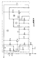
- the device of the invention can be realized, for example, according to the diagram represented on the figure 1 .
- the device comprises a measurement resistor R9 making it possible to measure a current flowing through a beam to be monitored.
- the device also comprises an amplifier circuit I which is intended to amplify current variations exceeding a predetermined threshold, which makes it possible to amplify only the large current variations, for example variations greater than 30 amperes / microsecond.
- the device of the invention then comprises a conditioning circuit II for transforming the profile of a measured current into a voltage representative of an energy to which the current corresponds, and a detector circuit III for detecting a level of energy. resulting from the anomaly and likely to cause a beam injury, including irreparable injury of the beam.
- the device of the invention finally comprises a signal generator making it possible to react to the anomaly observed, for example by generating an electric signal that can be used directly to power a control lamp or to actuate an acoustic alarm or a display means enabling for example, display the reference of the beam in which the anomaly was found.
- the filtering and the integration in the circuit makes it possible to eliminate current variations which originate from the normal operation of the electrical components of the vehicles, in particular at the time of starting or at the moment of the shutdown of an electrical component .
- the figure 2 shows the profile of a starter current with an amplitude of 1000 amperes, a rise time of 5 milliseconds, a descent time of 70 milliseconds and a settling time of 1 microsecond.
- the figure 3 represents an example of an impedance short circuit detected as a result of a beam injury with a current of 300 amps amplitude, a rise time of 50 microseconds, a descent time of 1 microsecond, a duration stabilization time of 10 microseconds and a period of 100 microseconds.
- the device of the invention thus makes it possible to detect through a parameterizable threshold, which is a function of the values of the resistors R12 and R22 of the circuit represented on the FIG. figure 1 , an energy level representing a beam injury.
- the device When the device detects a beam injury generating a strong impedance short-circuit, it can transmit the information to an optical or acoustic warning device installed for example on the dashboard of the motor vehicle. But it can also transmit this information to a centralized unit to inform the driver of the motor vehicle through a manager and information display of the vehicle so that the driver stops the vehicle in an emergency, just as the device can transmit the information also to the actuator for cutting the general power supply of the vehicle, especially when the span of the beam injury or multiple beams exceeds a predetermined value.
- a great advantage of the device of the invention is that it is entirely autonomous and in particular independent of all the vehicle components.
- the device of the invention provides protection of all the supply lines of a motor vehicle on all phases of life of the vehicle (park, storage, driving ).
- the device of the invention associated with a contactor, finally makes it possible to eliminate fuses whose effectiveness is not guaranteed or which are effective only in the presence of free short circuits or shocks occurring on the motor vehicle.
Landscapes
- Chemical & Material Sciences (AREA)
- Engineering & Computer Science (AREA)
- Combustion & Propulsion (AREA)
- Physics & Mathematics (AREA)
- General Physics & Mathematics (AREA)
- Testing Of Short-Circuits, Discontinuities, Leakage, Or Incorrect Line Connections (AREA)
- Emergency Protection Circuit Devices (AREA)
- Electric Propulsion And Braking For Vehicles (AREA)
Abstract
Description
La présente invention concerne un dispositif électronique permettant de détecter des anomalies dans des faisceaux électriques d'un véhicule automobile.The present invention relates to an electronic device for detecting anomalies in electrical harnesses of a motor vehicle.
Dans toute installation électrique, les lignes d'alimentation électrique sont protégées par des fusibles pour protéger les organes électriques, électroniques et/ou électromécaniques en cas de court-circuit ou de tout autre type de disfonctionnement ou d'anomalie qui pourrait se produire dans les lignes d'alimentation ou dans les organes. Les fusibles sont dimensionnés généralement selon l'intensité du courant de court-circuit, qui constitue le plus grand risque aussi bien pour les organes que pour les lignes d'alimentation et qu'il faut donc éviter.In any electrical installation, the power supply lines are protected by fuses to protect electrical, electronic and / or electromechanical devices in the event of a short circuit or any other type of malfunction or anomaly that may occur in feeding lines or in organs. Fuses are generally sized according to the intensity of the short-circuit current, which is the greatest risk for both organs and power lines and should be avoided.
Toutefois, des courts-circuits francs, c'est-à-dire des courts-circuits qui surviennent si rapidement que leur seule caractéristique est l'intensité du courant de court-circuit, se présentent seulement lorsque l'organe alimenté a une résistance purement ou quasi purement ohmique. Dans les autres cas, le court-circuit est impédant, c'est-à-dire il présente un profil de courant dans le temps avec une valeur maximale moins élevée que les mesures pourraient laisser penser dans un premier temps. Dans une telle situation, l'efficacité de la protection par un fusible n'est donc pas garantie.However, short-circuits, that is short-circuits which occur so rapidly that their only characteristic is the intensity of the short-circuit current, occur only when the energized device has a purely negative resistance. or almost purely ohmic. In other cases, the short circuit is impedant, that is to say it has a current profile in time with a lower maximum value that the measures might suggest initially. In such a situation, the effectiveness of the protection by a fuse is not guaranteed.
Le phénomène de court-circuit impédant est présent au début de chaque court-circuit, le temps nécessaire pour les différentes résistances de produire leur effet de limitateur de courant selon la caractéristique électrique individuelle. Lorsque ce phénomène de court-circuit impédant dépasse une certaine durée, généralement une seconde, il peut provoquer des échauffements importants dans l'organe et/ou dans la ligne d'alimentation. Les dommages de tels échauffements peuvent être irrémédiables, par exemple entraîner la destruction d'un composant ou d'un câble d'alimentation.The impedant short circuit phenomenon is present at the beginning of each short circuit, the time required for the different resistors to produce their current limiting effect according to the individual electrical characteristic. When this impedant short-circuit phenomenon exceeds a certain duration, generally a second, it can cause significant heating in the body and / or in the line Power. The damage of such heating may be irremediable, for example the destruction of a component or a power cable.
Dans des installations stationnaires et notamment dans des installations d'alimentation électrique de machines de puissance, on choisit le type de fusible non seulement selon l'intensité maximale admise sur la ligne électrique ou passant par l'organe, mais on choisit le fusible aussi selon la rapidité avec laquelle le fusible doit réagir.In stationary installations and particularly in power supply installations of power machines, the fuse type is chosen not only according to the maximum intensity allowed on the electrical line or passing through the body, but the fuse is also selected according to the speed with which the fuse must react.
En ce qui concerne le domaine automobile, la situation est moins confortable puisque les différentes lignes d'alimentation sont généralement réunies sous forme de faisceaux, ce qui favorise, par exemple, un échauffement réciproque des différentes lignes entre elles. De plus, les fusibles utilisés dans les véhicules automobiles exerçant leur fonction par fusion, la coupure d'une ligne d'alimentation ne se produit que lorsque le courant passant par cette ligne dépasse le courant de fusion du fusible.Regarding the automotive field, the situation is less comfortable since the various power lines are generally combined in the form of beams, which promotes, for example, a reciprocal heating of the different lines between them. In addition, the fuses used in motor vehicles carrying out their function by fusion, the cut of a power line occurs only when the current passing through this line exceeds the fusing current of the fuse.
En dehors de la protection de lignes d'alimentation électrique par des fusibles, on utilise parfois des moyens de protection contre des surcharges électriques destinées à protéger l'organe auquel ils sont attribués contre des surtensions ou éventuellement encore des moyens de protection destinés à couper une ligne d'alimentation lorsque l'organe en question est surchauffé. Dans un cas comme dans l'autre, ces moyens de protection sont destinés à être attribués individuellement à la protection d'un seul organe et en particulier à la protection interne d'un organe tel un moteur électrique. Pour des applications de ce type, ces moyens de protection sont très efficaces, par exemple en cas de blocage du rotor d'un moteur électrique entraînant un surchauffage du bobinage du moteur, mais pas en cas de courts-circuits.Apart from the protection of power supply lines by fuses, protection means against electrical overload are sometimes used to protect the member to which they are allocated against overvoltages or possibly also protection means intended to cut a voltage. feed line when the organ in question is overheated. In one case as in the other, these protection means are intended to be assigned individually to the protection of a single member and in particular to the internal protection of a member such as an electric motor. For applications of this type, these protection means are very effective, for example in case of blocking the rotor of an electric motor causing overheating of the motor winding, but not in case of short circuits.
Le document
Le document
En effet, la protection efficace des faisceaux électriques d'un véhicule automobile devrait être opérationnelle aussi pendant les périodes de stockage des véhicules automobiles.Indeed, the effective protection of the electrical harnesses of a motor vehicle should be operational also during periods of storage of motor vehicles.
Le but de l'invention est de remédier aux inconvénients énoncés ci avant et de proposer un moyen de protection efficace et simple pour la protection des faisceaux électriques d'un véhicule automobile.The object of the invention is to overcome the disadvantages mentioned above and to provide an effective and simple protection means for the protection of electrical harnesses of a motor vehicle.
Le but de l'invention est atteint avec un dispositif électronique permettant de détecter des anomalies dans des faisceaux électriques d'un véhicule automobile.The object of the invention is achieved with an electronic device for detecting anomalies in electrical harnesses of a motor vehicle.
Selon l'invention, le dispositif comprend une résistance de mesure permettant de mesurer un courant passant par un faisceau à surveiller, un circuit amplificateur destiné à amplifier des variations de courant dépassant un seuil prédéterminé, un circuit de conditionnement destiné à transformer le profil d'un courant mesuré en une tension représentative d'une énergie à laquelle correspond le courant, et un circuit détecteur permettant de détecter un niveau d'énergie, résultant de l'anomalie, susceptible de causer une blessure du faisceau, ainsi qu'un générateur de signal permettant de réagir à l'anomalie constatée.According to the invention, the device comprises a measurement resistor for measuring a current flowing through a beam to be monitored, an amplifier circuit for amplifying current variations exceeding a predetermined threshold, a conditioning circuit intended to transform the profile of a beam. a current measured in a voltage representative of an energy to which the current corresponds, and a detector circuit for detecting a level of energy resulting from the anomaly, likely to cause a beam injury, and a generator of signal to react to the anomaly found.
Le dispositif de l'invention est fondé sur la détermination de profils de courant exprimés en amplitude et en temps. Ces profils peuvent être mesurés au départ des câbles électriques sur la batterie. Les profils des courants sont ensuite traduits en terme d'énergie équivalente. Lorsque l'énergie équivalente dépasse un seuil prédéterminé, le dispositif dispose de l'information de présence d'un court-circuit impédant et engendre un signal exploitable soit pour alimenter un avertisseur optique ou acoustique, soit pour actionner un coupe-circuit et pour couper ainsi l'alimentation électrique avant que l'échauffement dans le faisceau protégé ne vienne générer des dommages irrémédiables.The device of the invention is based on the determination of current profiles expressed in amplitude and in time. These profiles can be measured from the electrical cables on the battery. Current profiles are then translated in terms of equivalent energy. When the equivalent energy exceeds a predetermined threshold, the device has the presence of an impedance short-circuit information and generates a signal that can be used either to supply an optical or acoustic alarm, to actuate a circuit breaker and to cut thus the power supply before the heating in the protected beam comes to generate irreparable damage.
Dans ce sens, la présente invention concerne également les caractéristiques ci-après considérées isolément ou sans toute combinaison techniquement possible :
- le dispositif comprend une source lumineuse et le générateur de signal est relié à la source lumineuse ;
- le générateur de signal comprend une sortie de signal permettant de relier le dispositif à un actionneur destiné à couper l'alimentation électrique au moins dans le faisceau surveillé ;
- le générateur de signal comprend une sortie de signal permettant de relier le dispositif à un moyen de commande et/ou de contrôle électronique d'au moins une partie des fonctions disponibles dans un véhicule automobile ;
- le générateur de signal comprend une sortie de signal permettant de relier le dispositif à une source lumineuse ou sonore.
- the device comprises a light source and the signal generator is connected to the light source;
- the signal generator comprises a signal output for connecting the device to an actuator for switching off the power supply at least in the monitored beam;
- the signal generator comprises a signal output for connecting the device to a means of control and / or electronic control of at least part of the functions available in a motor vehicle;
- the signal generator comprises a signal output for connecting the device to a light or sound source.
Le but de l'invention est également atteint avec un véhicule automobile équipé d'un dispositif électronique pour détecter des anomalies, qui a les caractéristiques énoncées plus haut et pour lequel les différents seuils évoqués sont déterminés spécifiquement selon l'équipement électrique du véhicule.The object of the invention is also achieved with a motor vehicle equipped with an electronic device for detecting anomalies, which has the characteristics listed above and for which the different thresholds evoked are determined specifically according to the electrical equipment of the vehicle.
D'autres caractéristiques et avantages de la présente invention ressortiront de la description ci-après de l'exemple de réalisation d'un dispositif de l'invention. La description est faite en référence aux dessins annexés dans lesquels
- la
figure 1 montre un schéma électrique du dispositif de l'invention, - la
figure 2 montre un diagramme d'un courant qui n'est pas détecté comme représentatif d'un disfonctionnement ou d'une anomalie et - la
figure 3 montre le diagramme d'un court-circuit impédant détecté à la suite d'une blessure de faisceau.
- the
figure 1 shows a circuit diagram of the device of the invention, - the
figure 2 shows a diagram of a current that is not detected as representative of a malfunction or anomaly and - the
figure 3 shows the diagram of an impedance short circuit detected as a result of a beam injury.
Le dispositif de l'invention peut être réalisé, par exemple, selon le schéma représenté sur la
Le dispositif de l'invention comprend enfin un générateur de signal permettant de réagir à l'anomalie constatée, par exemple en engendrant un signal électrique utilisable directement pour alimenter une lampe témoin ou pour actionner un avertisseur acoustique ou un moyen d'affichage permettant d'afficher par exemple la référence du faisceau dans lequel l'anomalie a été constatée.The device of the invention finally comprises a signal generator making it possible to react to the anomaly observed, for example by generating an electric signal that can be used directly to power a control lamp or to actuate an acoustic alarm or a display means enabling for example, display the reference of the beam in which the anomaly was found.
Le filtrage et l'intégration dans le circuit permet d'éliminer des variations de courant qui ont pour origine le fonctionnement normal des organes électriques des véhicules, notamment au moment de la mise en marche ou au moment de l'arrêt d'un organe électrique.The filtering and the integration in the circuit makes it possible to eliminate current variations which originate from the normal operation of the electrical components of the vehicles, in particular at the time of starting or at the moment of the shutdown of an electrical component .
A titre d'exemple pour un courant ne faisant pas état d'une anomalie, la
La
Le dispositif de l'invention permet de détecter ainsi au travers d'un seuil paramétrable, qui est fonction des valeurs des résistances R12 et R22 du circuit représenté sur la
Lorsque le dispositif détecte une blessure de faisceau engendrant un court-circuit impédant franc, il peut transmettre l'information à un avertisseur optique ou acoustique installé par exemple sur le tableau de bord du véhicule automobile. Mais il peut également transmettre cette information vers une unité centralisée pour informer le conducteur du véhicule automobile au travers d'un gestionnaire et afficheur d'information du véhicule afin que le conducteur arrête le véhicule en urgence, tout comme le dispositif peut transmettre l'information aussi à l'actionneur destiné à couper l'alimentation générale du véhicule, notamment lorsque l'envergure de la blessure du faisceau ou de plusieurs faisceaux dépasse une valeur prédéterminée.When the device detects a beam injury generating a strong impedance short-circuit, it can transmit the information to an optical or acoustic warning device installed for example on the dashboard of the motor vehicle. But it can also transmit this information to a centralized unit to inform the driver of the motor vehicle through a manager and information display of the vehicle so that the driver stops the vehicle in an emergency, just as the device can transmit the information also to the actuator for cutting the general power supply of the vehicle, especially when the span of the beam injury or multiple beams exceeds a predetermined value.
Un grand avantage du dispositif de l'invention est qu'il est entièrement autonome et notamment indépendant de l'ensemble des organes du véhicule. Le dispositif de l'invention assure une protection de l'ensemble des lignes d'alimentation d'un véhicule automobile sur toutes les phases de vie du véhicule (parc, stockage, roulage ...).A great advantage of the device of the invention is that it is entirely autonomous and in particular independent of all the vehicle components. The device of the invention provides protection of all the supply lines of a motor vehicle on all phases of life of the vehicle (park, storage, driving ...).
Le dispositif de l'invention, associé à un contacteur, permet enfin de supprimer des fusibles dont l'efficacité n'est pas garantie ou qui ne sont efficaces qu'en présence de courts-circuits francs ou de chocs intervenant sur le véhicule automobile.The device of the invention, associated with a contactor, finally makes it possible to eliminate fuses whose effectiveness is not guaranteed or which are effective only in the presence of free short circuits or shocks occurring on the motor vehicle.
Claims (7)
- Electronic device making it possible to detect anomalies in electrical harnesses of a motor vehicle and to protect these electrical harnesses, comprising a measurement resistor (R9) making it possible to measure an operating current passing through a harness to be monitored, an amplifier circuit (I) intended to amplify variations in current exceeding a predetermined threshold, a conditioning circuit (II) intended to transform the profile of a measured current into a voltage representative of an energy to which the current corresponds so as to eliminate variations in current which originate from the normal operation of the electrical members du vehicle, and a detector circuit (III) making it possible to detect an energy level, resulting from the anomaly, liable to cause an impairment to the harness, as well as a signal generator making it possible to react to the noted anomaly.
- Device according to Claim 1, characterized in that the transformation of a profile of a measured current into a voltage representative of an energy to which the current corresponds is intended to be performed by integration.
- Device according to any one of Claims 1 to 2, characterized in that it comprises a light source and in that the signal generator is linked to the light source.
- Device according to any one of Claims 1 to 3, characterized in that the signal generator comprises a signal output making it possible to link the device to an actuator intended to cut off the electrical power supply at least in the monitored harness.
- Device according to any one of Claims 1 to 4, characterized in that the signal generator comprises a signal output making it possible to link the device to an electronic command and/or control means for at least some of the functions available in a motor vehicle.
- Device according to Claim 1, characterized in that the signal generator comprises a signal output making it possible to link the device to a light source or audible source.
- Motor vehicle, characterized in that it comprises a device according to any one of Claims 1 to 6.
Applications Claiming Priority (1)
| Application Number | Priority Date | Filing Date | Title |
|---|---|---|---|
| FR0553242A FR2892522B1 (en) | 2005-10-25 | 2005-10-25 | ELECTRONIC DEVICE FOR DETECTING ANOMALIES IN ELECTRICAL BEAMS OF A MOTOR VEHICLE AND MOTOR VEHICLE HAVING SUCH A DEVICE |
Publications (2)
| Publication Number | Publication Date |
|---|---|
| EP1780552A1 EP1780552A1 (en) | 2007-05-02 |
| EP1780552B1 true EP1780552B1 (en) | 2008-09-10 |
Family
ID=36603409
Family Applications (1)
| Application Number | Title | Priority Date | Filing Date |
|---|---|---|---|
| EP06301074A Not-in-force EP1780552B1 (en) | 2005-10-25 | 2006-10-23 | Electronic device for diagnosing anomalies in electrical harnesses of a motor vehicle |
Country Status (4)
| Country | Link |
|---|---|
| EP (1) | EP1780552B1 (en) |
| AT (1) | ATE408148T1 (en) |
| DE (1) | DE602006002703D1 (en) |
| FR (1) | FR2892522B1 (en) |
Families Citing this family (1)
| Publication number | Priority date | Publication date | Assignee | Title |
|---|---|---|---|---|
| US9632125B2 (en) * | 2014-07-24 | 2017-04-25 | Ford Global Technologies, Llc | Harness anomaly detection systems and methods |
Family Cites Families (3)
| Publication number | Priority date | Publication date | Assignee | Title |
|---|---|---|---|---|
| US4684887A (en) * | 1986-06-24 | 1987-08-04 | General Battery Corporation | High voltage test confirmation apparatus |
| IT1293854B1 (en) * | 1997-06-25 | 1999-03-10 | Iveco Fiat | FAULT DETECTION DEVICE ALONG AN ELECTRICAL LINE OF A VEHICLE, PARTICULARLY AN INDUSTRIAL VEHICLE. |
| CA2369429C (en) * | 2001-01-25 | 2011-11-15 | Matsushita Electric Works, Ltd. | Method for discriminating abnormal current including arc current in ac load circuit and apparatus for executing the same |
-
2005
- 2005-10-25 FR FR0553242A patent/FR2892522B1/en not_active Expired - Fee Related
-
2006
- 2006-10-23 EP EP06301074A patent/EP1780552B1/en not_active Not-in-force
- 2006-10-23 AT AT06301074T patent/ATE408148T1/en not_active IP Right Cessation
- 2006-10-23 DE DE602006002703T patent/DE602006002703D1/en active Active
Also Published As
| Publication number | Publication date |
|---|---|
| ATE408148T1 (en) | 2008-09-15 |
| DE602006002703D1 (en) | 2008-10-23 |
| EP1780552A1 (en) | 2007-05-02 |
| FR2892522A1 (en) | 2007-04-27 |
| FR2892522B1 (en) | 2007-12-14 |
Similar Documents
| Publication | Publication Date | Title |
|---|---|---|
| EP2053741B1 (en) | Self-protected static electric switching device | |
| FR3084468A1 (en) | Method for diagnosing a switching means in a motor vehicle | |
| WO2015022329A1 (en) | Remote protection and switching device for electrical systems | |
| FR3088592A1 (en) | SAFETY DEVICE FOR VEHICLE ELECTRICAL CIRCUIT | |
| EP3399612A1 (en) | Electrical connection comprising an electrical protection - current bias device | |
| EP0390698B1 (en) | Defrosting-control system using overvoltage for an electrical windshield of an automotive vehicle | |
| EP2088674B1 (en) | Control and protection system for a low-side switch of an automation equipment | |
| EP1780552B1 (en) | Electronic device for diagnosing anomalies in electrical harnesses of a motor vehicle | |
| EP0080425A1 (en) | Operating, security and diagnostic device for the electrical system of a vehicle | |
| EP2494564B1 (en) | System for preventive diagnosis of contact impedance and overloads of a commutator | |
| FR2978324A1 (en) | Electronic device for forming motherboard of e.g. wheel antilock device, of car, has measurement unit formed with measuring path, voltage measuring device and microprocessor to measure electric current between connection points | |
| WO1999029007A1 (en) | Pre-loading device for an electric power system | |
| FR3067514B1 (en) | ELECTRICAL CONNECTION COMPRISING AN ELECTRICAL PROTECTION DEVICE - INTEGRITY TEST | |
| FR2978879A1 (en) | METHOD FOR DIAGNOSING A SHORT CIRCUIT IN AN ELECTRICAL ASSEMBLY OF A MOTOR VEHICLE COMPRISING A CAPACITIVE COMPONENT AND DIAGNOSTIC DEVICE | |
| FR2889775A1 (en) | METHOD AND ASSEMBLY FOR LIMITING THE DISSIPATION OF A SEMICONDUCTOR POWER SWITCH | |
| EP2396665B1 (en) | Method of detecting a short circuit and power supply module implementing same | |
| EP1764892A1 (en) | Device for monitoring a fault current at the output of an energy source in a vehicle | |
| FR2801441A1 (en) | Voltage limiter for over-voltage occurring in a vehicle power network, e.g. outlets of alternators of automotive vehicles | |
| WO2020109375A1 (en) | Device for protecting an electrical circuit, and electrical circuit comprising such a device | |
| EP1544049A1 (en) | System for power supply of the functional elements of a vehicle electrical system | |
| EP2882094B1 (en) | Method for discharging energy stored in a stator of an electric motor | |
| EP1492210A1 (en) | Protection system for at least part of a vehicle power supply network | |
| FR3097057A1 (en) | FAULTY ELECTRICAL CONNECTION DIAGNOSIS PROCESS IN AN ELECTRICAL SYSTEM | |
| WO2026027366A1 (en) | Method for protecting an electrical circuit branch of a motor vehicle | |
| FR2947111A1 (en) | ELECTRICAL CIRCUIT |
Legal Events
| Date | Code | Title | Description |
|---|---|---|---|
| PUAI | Public reference made under article 153(3) epc to a published international application that has entered the european phase |
Free format text: ORIGINAL CODE: 0009012 |
|
| AK | Designated contracting states |
Kind code of ref document: A1 Designated state(s): AT BE BG CH CY CZ DE DK EE ES FI FR GB GR HU IE IS IT LI LT LU LV MC NL PL PT RO SE SI SK TR |
|
| AX | Request for extension of the european patent |
Extension state: AL BA HR MK YU |
|
| 17P | Request for examination filed |
Effective date: 20071010 |
|
| 17Q | First examination report despatched |
Effective date: 20071105 |
|
| AKX | Designation fees paid |
Designated state(s): AT BE BG CH CY CZ DE DK EE ES FI FR GB GR HU IE IS IT LI LT LU LV MC NL PL PT RO SE SI SK TR |
|
| GRAP | Despatch of communication of intention to grant a patent |
Free format text: ORIGINAL CODE: EPIDOSNIGR1 |
|
| GRAS | Grant fee paid |
Free format text: ORIGINAL CODE: EPIDOSNIGR3 |
|
| GRAA | (expected) grant |
Free format text: ORIGINAL CODE: 0009210 |
|
| AK | Designated contracting states |
Kind code of ref document: B1 Designated state(s): AT BE BG CH CY CZ DE DK EE ES FI FR GB GR HU IE IS IT LI LT LU LV MC NL PL PT RO SE SI SK TR |
|
| REG | Reference to a national code |
Ref country code: GB Ref legal event code: FG4D Free format text: NOT ENGLISH |
|
| REG | Reference to a national code |
Ref country code: CH Ref legal event code: EP |
|
| REG | Reference to a national code |
Ref country code: IE Ref legal event code: FG4D Free format text: LANGUAGE OF EP DOCUMENT: FRENCH |
|
| REF | Corresponds to: |
Ref document number: 602006002703 Country of ref document: DE Date of ref document: 20081023 Kind code of ref document: P |
|
| REG | Reference to a national code |
Ref country code: GB Ref legal event code: 746 Effective date: 20081222 |
|
| PG25 | Lapsed in a contracting state [announced via postgrant information from national office to epo] |
Ref country code: LT Free format text: LAPSE BECAUSE OF FAILURE TO SUBMIT A TRANSLATION OF THE DESCRIPTION OR TO PAY THE FEE WITHIN THE PRESCRIBED TIME-LIMIT Effective date: 20080910 |
|
| PG25 | Lapsed in a contracting state [announced via postgrant information from national office to epo] |
Ref country code: AT Free format text: LAPSE BECAUSE OF FAILURE TO SUBMIT A TRANSLATION OF THE DESCRIPTION OR TO PAY THE FEE WITHIN THE PRESCRIBED TIME-LIMIT Effective date: 20080910 Ref country code: SI Free format text: LAPSE BECAUSE OF FAILURE TO SUBMIT A TRANSLATION OF THE DESCRIPTION OR TO PAY THE FEE WITHIN THE PRESCRIBED TIME-LIMIT Effective date: 20080910 Ref country code: LV Free format text: LAPSE BECAUSE OF FAILURE TO SUBMIT A TRANSLATION OF THE DESCRIPTION OR TO PAY THE FEE WITHIN THE PRESCRIBED TIME-LIMIT Effective date: 20080910 Ref country code: FI Free format text: LAPSE BECAUSE OF FAILURE TO SUBMIT A TRANSLATION OF THE DESCRIPTION OR TO PAY THE FEE WITHIN THE PRESCRIBED TIME-LIMIT Effective date: 20080910 |
|
| NLV1 | Nl: lapsed or annulled due to failure to fulfill the requirements of art. 29p and 29m of the patents act | ||
| REG | Reference to a national code |
Ref country code: IE Ref legal event code: FD4D |
|
| BERE | Be: lapsed |
Owner name: PEUGEOT CITROEN AUTOMOBILES SA Effective date: 20081031 |
|
| PG25 | Lapsed in a contracting state [announced via postgrant information from national office to epo] |
Ref country code: ES Free format text: LAPSE BECAUSE OF FAILURE TO SUBMIT A TRANSLATION OF THE DESCRIPTION OR TO PAY THE FEE WITHIN THE PRESCRIBED TIME-LIMIT Effective date: 20081221 Ref country code: BG Free format text: LAPSE BECAUSE OF FAILURE TO SUBMIT A TRANSLATION OF THE DESCRIPTION OR TO PAY THE FEE WITHIN THE PRESCRIBED TIME-LIMIT Effective date: 20081210 Ref country code: IE Free format text: LAPSE BECAUSE OF FAILURE TO SUBMIT A TRANSLATION OF THE DESCRIPTION OR TO PAY THE FEE WITHIN THE PRESCRIBED TIME-LIMIT Effective date: 20080910 |
|
| PG25 | Lapsed in a contracting state [announced via postgrant information from national office to epo] |
Ref country code: CZ Free format text: LAPSE BECAUSE OF FAILURE TO SUBMIT A TRANSLATION OF THE DESCRIPTION OR TO PAY THE FEE WITHIN THE PRESCRIBED TIME-LIMIT Effective date: 20080910 Ref country code: IS Free format text: LAPSE BECAUSE OF FAILURE TO SUBMIT A TRANSLATION OF THE DESCRIPTION OR TO PAY THE FEE WITHIN THE PRESCRIBED TIME-LIMIT Effective date: 20090110 Ref country code: PT Free format text: LAPSE BECAUSE OF FAILURE TO SUBMIT A TRANSLATION OF THE DESCRIPTION OR TO PAY THE FEE WITHIN THE PRESCRIBED TIME-LIMIT Effective date: 20090210 Ref country code: RO Free format text: LAPSE BECAUSE OF FAILURE TO SUBMIT A TRANSLATION OF THE DESCRIPTION OR TO PAY THE FEE WITHIN THE PRESCRIBED TIME-LIMIT Effective date: 20080910 Ref country code: SK Free format text: LAPSE BECAUSE OF FAILURE TO SUBMIT A TRANSLATION OF THE DESCRIPTION OR TO PAY THE FEE WITHIN THE PRESCRIBED TIME-LIMIT Effective date: 20080910 Ref country code: MC Free format text: LAPSE BECAUSE OF NON-PAYMENT OF DUE FEES Effective date: 20081031 Ref country code: NL Free format text: LAPSE BECAUSE OF FAILURE TO SUBMIT A TRANSLATION OF THE DESCRIPTION OR TO PAY THE FEE WITHIN THE PRESCRIBED TIME-LIMIT Effective date: 20080910 |
|
| PLBE | No opposition filed within time limit |
Free format text: ORIGINAL CODE: 0009261 |
|
| STAA | Information on the status of an ep patent application or granted ep patent |
Free format text: STATUS: NO OPPOSITION FILED WITHIN TIME LIMIT |
|
| PG25 | Lapsed in a contracting state [announced via postgrant information from national office to epo] |
Ref country code: DK Free format text: LAPSE BECAUSE OF FAILURE TO SUBMIT A TRANSLATION OF THE DESCRIPTION OR TO PAY THE FEE WITHIN THE PRESCRIBED TIME-LIMIT Effective date: 20080910 Ref country code: EE Free format text: LAPSE BECAUSE OF FAILURE TO SUBMIT A TRANSLATION OF THE DESCRIPTION OR TO PAY THE FEE WITHIN THE PRESCRIBED TIME-LIMIT Effective date: 20080910 |
|
| 26N | No opposition filed |
Effective date: 20090611 |
|
| PG25 | Lapsed in a contracting state [announced via postgrant information from national office to epo] |
Ref country code: IT Free format text: LAPSE BECAUSE OF FAILURE TO SUBMIT A TRANSLATION OF THE DESCRIPTION OR TO PAY THE FEE WITHIN THE PRESCRIBED TIME-LIMIT Effective date: 20080910 |
|
| PG25 | Lapsed in a contracting state [announced via postgrant information from national office to epo] |
Ref country code: BE Free format text: LAPSE BECAUSE OF NON-PAYMENT OF DUE FEES Effective date: 20081031 |
|
| PG25 | Lapsed in a contracting state [announced via postgrant information from national office to epo] |
Ref country code: SE Free format text: LAPSE BECAUSE OF FAILURE TO SUBMIT A TRANSLATION OF THE DESCRIPTION OR TO PAY THE FEE WITHIN THE PRESCRIBED TIME-LIMIT Effective date: 20081210 |
|
| PG25 | Lapsed in a contracting state [announced via postgrant information from national office to epo] |
Ref country code: PL Free format text: LAPSE BECAUSE OF FAILURE TO SUBMIT A TRANSLATION OF THE DESCRIPTION OR TO PAY THE FEE WITHIN THE PRESCRIBED TIME-LIMIT Effective date: 20080910 |
|
| PG25 | Lapsed in a contracting state [announced via postgrant information from national office to epo] |
Ref country code: HU Free format text: LAPSE BECAUSE OF FAILURE TO SUBMIT A TRANSLATION OF THE DESCRIPTION OR TO PAY THE FEE WITHIN THE PRESCRIBED TIME-LIMIT Effective date: 20090311 Ref country code: CY Free format text: LAPSE BECAUSE OF FAILURE TO SUBMIT A TRANSLATION OF THE DESCRIPTION OR TO PAY THE FEE WITHIN THE PRESCRIBED TIME-LIMIT Effective date: 20080910 Ref country code: LU Free format text: LAPSE BECAUSE OF NON-PAYMENT OF DUE FEES Effective date: 20081023 |
|
| PG25 | Lapsed in a contracting state [announced via postgrant information from national office to epo] |
Ref country code: TR Free format text: LAPSE BECAUSE OF FAILURE TO SUBMIT A TRANSLATION OF THE DESCRIPTION OR TO PAY THE FEE WITHIN THE PRESCRIBED TIME-LIMIT Effective date: 20080910 |
|
| PG25 | Lapsed in a contracting state [announced via postgrant information from national office to epo] |
Ref country code: GR Free format text: LAPSE BECAUSE OF FAILURE TO SUBMIT A TRANSLATION OF THE DESCRIPTION OR TO PAY THE FEE WITHIN THE PRESCRIBED TIME-LIMIT Effective date: 20081211 |
|
| REG | Reference to a national code |
Ref country code: CH Ref legal event code: PL |
|
| PG25 | Lapsed in a contracting state [announced via postgrant information from national office to epo] |
Ref country code: CH Free format text: LAPSE BECAUSE OF NON-PAYMENT OF DUE FEES Effective date: 20101031 Ref country code: LI Free format text: LAPSE BECAUSE OF NON-PAYMENT OF DUE FEES Effective date: 20101031 |
|
| REG | Reference to a national code |
Ref country code: FR Ref legal event code: PLFP Year of fee payment: 11 |
|
| REG | Reference to a national code |
Ref country code: FR Ref legal event code: PLFP Year of fee payment: 12 |
|
| REG | Reference to a national code |
Ref country code: FR Ref legal event code: CA Effective date: 20180312 Ref country code: FR Ref legal event code: CD Owner name: PEUGEOT CITROEN AUTOMOBILES SA, FR Effective date: 20180312 |
|
| REG | Reference to a national code |
Ref country code: FR Ref legal event code: PLFP Year of fee payment: 13 |
|
| PGFP | Annual fee paid to national office [announced via postgrant information from national office to epo] |
Ref country code: FR Payment date: 20190919 Year of fee payment: 14 |
|
| PGFP | Annual fee paid to national office [announced via postgrant information from national office to epo] |
Ref country code: GB Payment date: 20190923 Year of fee payment: 14 |
|
| PGFP | Annual fee paid to national office [announced via postgrant information from national office to epo] |
Ref country code: DE Payment date: 20190918 Year of fee payment: 14 |
|
| REG | Reference to a national code |
Ref country code: DE Ref legal event code: R119 Ref document number: 602006002703 Country of ref document: DE |
|
| GBPC | Gb: european patent ceased through non-payment of renewal fee |
Effective date: 20201023 |
|
| PG25 | Lapsed in a contracting state [announced via postgrant information from national office to epo] |
Ref country code: FR Free format text: LAPSE BECAUSE OF NON-PAYMENT OF DUE FEES Effective date: 20201031 Ref country code: DE Free format text: LAPSE BECAUSE OF NON-PAYMENT OF DUE FEES Effective date: 20210501 |
|
| PG25 | Lapsed in a contracting state [announced via postgrant information from national office to epo] |
Ref country code: GB Free format text: LAPSE BECAUSE OF NON-PAYMENT OF DUE FEES Effective date: 20201023 |