EP1764892A1 - Device for monitoring a fault current at the output of an energy source in a vehicle - Google Patents
Device for monitoring a fault current at the output of an energy source in a vehicle Download PDFInfo
- Publication number
- EP1764892A1 EP1764892A1 EP06120643A EP06120643A EP1764892A1 EP 1764892 A1 EP1764892 A1 EP 1764892A1 EP 06120643 A EP06120643 A EP 06120643A EP 06120643 A EP06120643 A EP 06120643A EP 1764892 A1 EP1764892 A1 EP 1764892A1
- Authority
- EP
- European Patent Office
- Prior art keywords
- current
- branch
- switch
- measuring
- analysis
- Prior art date
- Legal status (The legal status is an assumption and is not a legal conclusion. Google has not performed a legal analysis and makes no representation as to the accuracy of the status listed.)
- Withdrawn
Links
Images


Classifications
-
- H—ELECTRICITY
- H02—GENERATION; CONVERSION OR DISTRIBUTION OF ELECTRIC POWER
- H02H—EMERGENCY PROTECTIVE CIRCUIT ARRANGEMENTS
- H02H3/00—Emergency protective circuit arrangements for automatic disconnection directly responsive to an undesired change from normal electric working condition with or without subsequent reconnection ; integrated protection
- H02H3/08—Emergency protective circuit arrangements for automatic disconnection directly responsive to an undesired change from normal electric working condition with or without subsequent reconnection ; integrated protection responsive to excess current
- H02H3/087—Emergency protective circuit arrangements for automatic disconnection directly responsive to an undesired change from normal electric working condition with or without subsequent reconnection ; integrated protection responsive to excess current for dc applications
-
- H—ELECTRICITY
- H02—GENERATION; CONVERSION OR DISTRIBUTION OF ELECTRIC POWER
- H02H—EMERGENCY PROTECTIVE CIRCUIT ARRANGEMENTS
- H02H7/00—Emergency protective circuit arrangements specially adapted for specific types of electric machines or apparatus or for sectionalised protection of cable or line systems, and effecting automatic switching in the event of an undesired change from normal working conditions
- H02H7/18—Emergency protective circuit arrangements specially adapted for specific types of electric machines or apparatus or for sectionalised protection of cable or line systems, and effecting automatic switching in the event of an undesired change from normal working conditions for batteries; for accumulators
Definitions
- the object of the invention relates to a device for detecting the appearance of a fault current at the output of an energy source of a motor vehicle.
- the object of the invention finds a particularly advantageous application in the field of monitoring a battery of a motor vehicle to prevent its discharge.
- a motor vehicle In general, a motor vehicle is equipped with at least one battery which, even when the vehicle is stationary, supplies certain electrical and / or electronic equipment for a fixed period of time. This is the case of anti-theft devices, door locking systems, security lights, etc. In the same direction, certain equipment such as computers, electronic circuits or actuators regularly request the supply of an electrical energy to ensure different associated functions.
- a monitoring device comprises a current measuring circuit with a resistance interposed between the output of the battery and the charges supplied by the battery.
- Such a device also comprises a management unit which, depending on the measurement of the current, controls the opening of a switch mounted at the output of the battery to disconnect loads in the event of the appearance of a fault current.
- the measurement resistance traversed by the current generates a voltage drop, which decreases the voltage applied to the energized loads.
- the current passing through this resistance during the vehicle running phases is important (a few hundred amperes) as well as during current requests by the computers or actuators during the stopping phases of the vehicle (a few tens of amps). ).
- the object of the invention is therefore to provide a device for accurately measuring, via ohmic resistance, a fault current such as a short-circuit or a leakage current, without causing a voltage drop. high compared to the charges powered by the battery.
- the device for monitoring the appearance of a fault current at the output of at least one energy source of a vehicle, supplying a series of electric charges is intended to be mounted to the output of the energy source which has, on the one hand, a highly current operating mode corresponding to a current supply of the electrical charges and, on the other hand, a mode of operation out of high current.
- the analysis and control means control the opening of cut-off means during the detection of the appearance of a fault current.
- the breaking means consist of at least one switch connected in series in the measuring branch.
- the breaking means consist of a switch placed at the output of the energy source or in series with at least one electric charge.
- the analysis and control means control the opening of the switch connected in series in the measuring branch when the power source is in a high current mode.
- the current measuring means comprises a resistor and a circuit for measuring the current flowing through the resistor.
- the current means provide a measurement of the current flowing in the measuring branch when the switch is closed.
- the analysis and control means ensure the opening of the breaking means and the switch placed in the branch branch according to the stopping state of the vehicle .
- the analysis and control means control the closing of the breaking means to allow a measurement of current in the measurement branch.
- the analysis and control means are an integral part of the device or are wholly or partly deported in a computer.
- Another object of the invention is to propose a system for monitoring the electrical state of a vehicle comprising a device according to the invention.
- the object of the invention relates to a device 1 adapted to monitor the appearance of a fault current at the output of at least one energy source 2 of a motor vehicle.
- the energy source 2 supplies a series of electric charges 3 and is composed of a battery connected in parallel with an alternator.
- the monitoring device 1 is intended to be mounted at the output of the energy source 2.
- the device 1 is in the form of a housing interposed between the energy source 2 and the electric charges 3.
- the monitoring device 1 comprises a branch 5 of current measurement connected in parallel with a branch branch 7 which has an electrical resistance lower than the electrical resistance of the measuring branch 5.
- the measuring branch 5 is equipped with a resistor 8 called shunt forming part of measuring means current 9.
- Branch branch 7 comprises at least one controlled switch 11 for opening or closing branch branch 7. It must be considered that branch branch 7 is weakly resistive so that the resistance is for example less than 10 m ⁇ and preferably between 1 and 10 m ⁇ .
- the measuring branch 5 is highly resistive so that the resistance is for example greater than 100 m ⁇ and typically of the order of a few hundred m ⁇ , and preferably between 100 m ⁇ and 10 ⁇ .
- the resistance of the branch branch 7 and the resistance of the measuring branch 5 are known and determined at values indicated above.
- the measuring means 9 also comprises a measuring circuit 12 for the current flowing through the measuring branch 5 and more precisely the resistor 8.
- This measuring circuit 12 can be produced in any appropriate manner, for example by implementing an amplifier placed at the terminals resistance 8.
- the monitoring device 1 also comprises analysis and control means 13 connected to the controlled switch 11 and to the measuring circuit 12. These analysis and control means 13 are also connected to information means 15 giving information on the state of the energy supplied by the energy source 2.
- the energy source 2 has a high current mode of operation and a mode of operation out of strong current.
- the high-current operating mode appears when the vehicle is running (a few hundred amperes) or when the vehicle is stationary but certain loads such as actuators or computers require a current for a specified period of time (a few tens of amps).
- the energy source 2 also has a mode of operation out of high current that can be described as operating mode at low current.
- the information means 15 provide the analysis and control means 13 with information on the operating state of the energy source (high current mode or off-current mode) which depends on the energy demands of the various loads 3.
- the analysis and control means 13 thus make it possible, on the one hand, to close the switch 11 when the battery is operating in a high current mode and, on the other hand, when the battery is in a high current mode, to open the switch. 11 and measure the current flowing in the measuring branch 5 to detect the occurrence of a fault current.
- branch branch 7 is closed so that it appears a very low resistance and therefore a very small drop in voltage even though the circulating current can be of significant value.
- a resistance of a few m ⁇ may be provided for branch branch 7 so that there is a slight voltage drop below Volt.
- the shunt is all the better that the resistance of the shunt branch 7 is much smaller than the resistance of the measurement branch 5.
- the measuring means 9 can provide a measurement of the current flowing in the measuring branch 5. This measurement of the current flowing in the measuring branch 5 makes it possible to know the total current supplied by the battery in so far as is known the ratio of the resistances between the branch branch 7 and the measuring branch 5.
- the bypass branch 7 is opened by the opening of the switch 11, so that the current passes only in the measurement branch 5.
- the analysis and control means 13 thus make it possible to detect the appearance of a fault current at the terminals of the energy source 2.
- the monitoring device 1 thus makes it possible to accurately measure the current while not causing a voltage drop of the energy source. It should be noted that this current measurement is effective mainly when discharged as a source of energy 2, the battery.
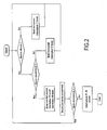
- Fig. 2 makes it possible to explain the operation of the monitoring device according to the invention.
- the monitoring device 1 takes into account as information the running of the vehicle. If the vehicle is running, the analysis and control means 13 control the closing of the controlled switch 11 so that the power source can be discharged into the loads 3 via the branch branch 7. If the vehicle is at stopping, the monitoring device 1 takes into account whether or not there appears to be a high current requirement with at least one load. If the need for a high current appears, the analysis and control means 13 control the closing of the controlled switch 11 in order to supply the loads 3, via the branch branch 7.
- the analysis and control means 13 control the opening of the switch 11 of the branch branch 7 and the closing of the switch 16 of the measurement branch 5.
- the means 12 measure the current flowing in the measuring branch 5 in order to assess whether the current flowing or not corresponds to a fault current.
- Fig. 3 illustrates a preferred embodiment in which the analysis and control means 13 control the opening of cut-off means 16 during the detection of the appearance of a fault current.
- the switching means 16 are constituted by at least one switch connected in series in the measurement branch 5.
- the analysis and control means 13 When the analysis and control means 13 detect the appearance of a fault current, the analysis and control means 13 control the opening of the switch 16 in order to disconnect the charges 3 from the source of the fault. energy. When both switches 11 and 16 are in the open position, the energy source 2 is isolated and protected from inadvertent discharge.
- the analysis and control means 13 also take into account according to the embodiment variant illustrated in FIG. 3, a disconnect command if the value of the measured current exceeds a determined value or does not correspond to a particular demand of a load.
- the switch 16 is open.
- the analysis and control means 13 can control the opening of the switch 16 as a function of the stopping state of the vehicle.
- the switch 16 can be opened following a desire to disconnect the energy source for example before the marketing of the vehicle or following a prolonged stop of the vehicle for a predetermined period.
- the monitoring device In the case where the disconnection order is not given, the monitoring device remains in this state until a different information does not appear at the level of the running of the vehicle or a current requirement.
- the switch 16 is preferably placed in the measuring branch 5.
- the switch 16 can be placed directly at the output of the energy source or in series with one or more electric charges 3.
- the analysis and control means 13 can control the opening of the switch 16 placed in the measurement branch 5 when the power source is in a high current mode, that is, that is, when the switch 11 is closed.
- the switch 16 is closed by the analysis and control means 13 when a measurement of current is made, in off-current mode or in strong current mode.
- the analysis and control means 13 are considered to be an integral part of the device 1. Of course, it can be envisaged that these analysis and control means 13 are wholly or partly remote to the outside. of the device 1. Thus, part or all of the analysis and control means 13 can be deported in a computer associated with the vehicle.
- the monitoring device 1 can be part of a system for monitoring the electrical state of the vehicle.
- the device 1 can be integrated into a system for monitoring or protecting the battery against a discharge or to protect a vehicle against fire.
Abstract
Description
L'objet de l'invention concerne un dispositif pour détecter l'apparition d'un courant de défaut à la sortie d'une source d'énergie d'un véhicule automobile.The object of the invention relates to a device for detecting the appearance of a fault current at the output of an energy source of a motor vehicle.
L'objet de l'invention trouve une application particulièrement avantageuse dans le domaine de la surveillance d'une batterie d'un véhicule automobile afin d'éviter sa décharge.The object of the invention finds a particularly advantageous application in the field of monitoring a battery of a motor vehicle to prevent its discharge.
D'une manière générale, un véhicule automobile est équipé d'au moins une batterie qui même lorsque le véhicule est à l'arrêt, alimente certains équipements électriques et/ou électroniques selon une durée déterminée. C'est ainsi le cas des dispositifs anti-vols, des systèmes de verrouillage des portes, des feux de sécurité, etc.. Dans le même sens, certains équipements tels que des calculateurs, des circuits électroniques ou des actionneurs demandent régulièrement la fourniture d'une énergie électrique afin d'assurer différentes fonctions associées.In general, a motor vehicle is equipped with at least one battery which, even when the vehicle is stationary, supplies certain electrical and / or electronic equipment for a fixed period of time. This is the case of anti-theft devices, door locking systems, security lights, etc. In the same direction, certain equipment such as computers, electronic circuits or actuators regularly request the supply of an electrical energy to ensure different associated functions.
Des pannes ou des courts-circuits intervenant sur certains équipements électriques ou électroniques peuvent conduire à une décharge complète de la batterie. Il apparaît ainsi des courts-circuits de type résistif avec un courant qui ne dépasse pas quelques dizaines d'ampères, ne permettant pas de faire jouer les fusibles de protection pouvant entraîner une décharge de batterie, voire un incendie du véhicule. D'une manière générale, il apparaît le besoin de mesurer précisément un courant de défaut provenant d'un court-circuit ou d'un courant de fuite. L'état de la technique a proposé différentes solutions afin de détecter l'apparition d'un courant de défaut.Failures or short circuits on certain electrical or electronic equipment can lead to a complete discharge of the battery. It thus appears resistive-type short circuits with a current that does not exceed a few tens of amperes, not allowing to play the protection fuses that can lead to a battery discharge, or even a fire of the vehicle. In general, it appears the need to accurately measure a fault current from a short circuit or a leakage current. The state of the art has proposed different solutions to detect the appearance of a fault current.
De manière générale, un dispositif de surveillance comporte un circuit de mesure de courant avec une résistance interposée entre la sortie de la batterie et les charges alimentées par la batterie. Un tel dispositif comporte également une unité de gestion qui en fonction de la mesure du courant pilote l'ouverture d'un interrupteur monté à la sortie de la batterie pour déconnecter des charges en cas d'apparition d'un courant de défaut.In general, a monitoring device comprises a current measuring circuit with a resistance interposed between the output of the battery and the charges supplied by the battery. Such a device also comprises a management unit which, depending on the measurement of the current, controls the opening of a switch mounted at the output of the battery to disconnect loads in the event of the appearance of a fault current.
Il doit être considéré que la résistance de mesure traversée par le courant est génératrice d'une chute de tension, ce qui diminue d'autant la tension appliquée aux charges alimentées. En effet, le courant traversant cette résistance lors des phases de marche du véhicule est important (quelques centaines d'ampères) ainsi que lors des demandes en courant par les calculateurs ou actionneurs pendant les phases d'arrêt du véhicule (quelques dizaines d'ampères). Par ailleurs, pour obtenir une mesure précise du courant de manière à optimiser la qualité de détection des défauts, il apparaît nécessaire de réaliser une mesure sur une faible gamme de valeurs, par exemple de l'ordre de plus ou moins 1 ampère. Aussi, pour avoir une mesure précise de courant sur une gamme de faible valeur, il apparaît nécessaire que la résistance de mesure traversée par le courant présente une grande valeur ohmique, ce qui entraîne une chute de tension élevée à fort courant. Il existe donc une incompatibilité entre d'une part, une mesure résistive précise sur une faible gamme de valeurs et d'autre part, une faible chute de tension alors que le courant délivré par la batterie et traversant la résistance présente une valeur importante.It must be considered that the measurement resistance traversed by the current generates a voltage drop, which decreases the voltage applied to the energized loads. Indeed, the current passing through this resistance during the vehicle running phases is important (a few hundred amperes) as well as during current requests by the computers or actuators during the stopping phases of the vehicle (a few tens of amps). ). Furthermore, to obtain an accurate measurement of the current so as to optimize the quality of detection of defects, it appears necessary to perform a measurement over a small range of values, for example of the order of plus or minus 1 ampere. Also, to have a precise measurement of current over a range of low value, it appears necessary that the measurement resistance traversed by the current has a high ohmic value, which causes a high voltage drop at high current. There is therefore an incompatibility between, on the one hand, a precise resistive measurement over a small range of values and, on the other hand, a small voltage drop while the current delivered by the battery and passing through the resistor has a significant value.
L'objet de l'invention vise donc à proposer un dispositif permettant de pouvoir mesurer de manière précise, via une résistance ohmique, un courant de défaut tel qu'un court-circuit ou un courant de fuite, sans toutefois entraîner une chute de tension élevée par rapport aux charges alimentées par la batterie.The object of the invention is therefore to provide a device for accurately measuring, via ohmic resistance, a fault current such as a short-circuit or a leakage current, without causing a voltage drop. high compared to the charges powered by the battery.
Pour atteindre un tel objectif, le dispositif pour surveiller l'apparition d'un courant de défaut à la sortie d'au moins une source d'énergie d'un véhicule, alimentant une série de charges électriques, est destiné à être monté à la sortie de la source d'énergie qui présente d'une part, un mode de fonctionnement fort courant correspondant à une fourniture en courant des charges électriques et d'autre part, un mode de fonctionnement hors fort courant.To achieve such an objective, the device for monitoring the appearance of a fault current at the output of at least one energy source of a vehicle, supplying a series of electric charges, is intended to be mounted to the output of the energy source which has, on the one hand, a highly current operating mode corresponding to a current supply of the electrical charges and, on the other hand, a mode of operation out of high current.
Selon l'invention, le dispositif comporte :
- une branche de mesure de courant montée en parallèle d'une branche de dérivation présentant une résistance électrique inférieure de celle de la branche de mesure,
- des moyens de mesure du courant circulant dans la branche de mesure,
- au moins un interrupteur commandé placé dans la branche de dérivation,
- et des moyens d'analyse et de commande reliés à l'interrupteur commandé, aux moyens de mesure et à des moyens d'information sur l'état de l'énergie fourni par la source d'énergie, ces moyens d'analyse et de commande permettant d'une part, de fermer l'interrupteur lorsque la source d'énergie fonctionne en mode fort courant, et d'autre part, lorsque la source d'énergie est en mode hors fort courant, d'ouvrir l'interrupteur et de mesurer de manière précise le courant afin de détecter l'apparition d'un courant de défaut.
- a current measuring branch connected in parallel with a branch branch having a lower electrical resistance than that of the measuring branch,
- means for measuring the current flowing in the measurement branch,
- at least one controlled switch placed in the branch branch,
- and analysis and control means connected to the controlled switch, to the measuring means and to information means on the state of the energy supplied by the energy source, these means for analyzing and controlling command on the one hand, to close the switch when the energy source operates in high current mode, and secondly, when the power source is in high current mode, to open the switch and accurately measuring the current to detect the occurrence of a fault current.
Selon une variante préférée de réalisation, les moyens d'analyse et de commande pilotent l'ouverture de moyens de coupure lors de la détection de l'apparition d'un courant de défaut.According to a preferred embodiment, the analysis and control means control the opening of cut-off means during the detection of the appearance of a fault current.
Avantageusement, les moyens de coupure sont constitués par au moins un interrupteur monté en série dans la branche de mesure.Advantageously, the breaking means consist of at least one switch connected in series in the measuring branch.
Selon un autre mode de réalisation, les moyens de coupure sont constitués par un interrupteur placé à la sortie de la source d'énergie ou en série avec au moins une charge électrique.According to another embodiment, the breaking means consist of a switch placed at the output of the energy source or in series with at least one electric charge.
Selon un exemple de mise en oeuvre de l'invention, les moyens d'analyse et de commande pilotent l'ouverture de l'interrupteur monté en série dans la branche de mesure lorsque la source d'énergie est en mode fort courant.According to an exemplary implementation of the invention, the analysis and control means control the opening of the switch connected in series in the measuring branch when the power source is in a high current mode.
Selon un exemple de réalisation, les moyens de mesure de courant comporte une résistance et un circuit de mesure du courant traversant la résistance.According to an exemplary embodiment, the current measuring means comprises a resistor and a circuit for measuring the current flowing through the resistor.
Selon un autre mode de réalisation, les moyens de courant assurent une mesure du courant circulant dans la branche de mesure lorsque l'interrupteur est fermé.According to another embodiment, the current means provide a measurement of the current flowing in the measuring branch when the switch is closed.
Selon un exemple de mise en oeuvre de l'invention, les moyens d'analyse et de commande assurent l'ouverture des moyens de coupure et de l'interrupteur placé dans la branche de dérivation en fonction de l'état d'arrêt du véhicule.According to an exemplary implementation of the invention, the analysis and control means ensure the opening of the breaking means and the switch placed in the branch branch according to the stopping state of the vehicle .
De même, les moyens d'analyse et de commande pilotent la fermeture des moyens de coupure pour permettre une mesure de courant dans la branche de mesure.Similarly, the analysis and control means control the closing of the breaking means to allow a measurement of current in the measurement branch.
Par exemple, les moyens d'analyse et de commande font partie intégrante du dispositif ou sont tout ou partie déportés dans un calculateur.For example, the analysis and control means are an integral part of the device or are wholly or partly deported in a computer.
Un autre objet de l'invention est de proposer un système de surveillance de l'état électrique d'un véhicule comportant un dispositif conforme à l'invention.Another object of the invention is to propose a system for monitoring the electrical state of a vehicle comprising a device according to the invention.
Diverses autres caractéristiques ressortent de la description faite ci-dessous en référence aux dessins annexés qui montrent, à titre d'exemples non limitatifs, des formes de réalisation de l'objet de l'invention.
- La Figure 1 est une vue schématique d'un premier exemple de réalisation d'un dispositif de surveillance conforme à l'invention.
- La Figure 2 est un schéma synoptique permettant de décrire le fonctionnement du dispositif de surveillance conforme à l'invention.
- La Figure 3 est un schéma illustrant une variante de réalisation du dispositif de surveillance conforme à l'invention.
- Figure 1 is a schematic view of a first embodiment of a monitoring device according to the invention.
- Figure 2 is a block diagram for describing the operation of the monitoring device according to the invention.
- Figure 3 is a diagram illustrating an alternative embodiment of the monitoring device according to the invention.
Tel que cela ressort de la Fig. 1, l'objet de l'invention concerne un dispositif 1 adapté pour surveiller l'apparition d'un courant de défaut à la sortie d'au moins une source d'énergie 2 d'un véhicule automobile. De manière classique, la source d'énergie 2 alimente une série de charges électriques 3 et se trouve composée d'une batterie montée en parallèle d'un alternateur.As can be seen from FIG. 1, the object of the invention relates to a device 1 adapted to monitor the appearance of a fault current at the output of at least one
Le dispositif de surveillance 1 est destiné à être monté à la sortie de la source d'énergie 2. Par exemple, le dispositif 1 se présente sous la forme d'un boîtier interposé entre la source d'énergie 2 et les charges électriques 3. Le dispositif de surveillance 1 comporte une branche 5 de mesure de courant montée en parallèle d'une branche de dérivation 7 qui présente une résistance électrique inférieure à la résistance électrique de la branche de mesure 5. La branche de mesure 5 est équipée d'une résistance 8 dite shunt faisant partie de moyens de mesure de courant 9. The monitoring device 1 is intended to be mounted at the output of the
La branche de dérivation 7 comporte au moins un interrupteur commandé 11 permettant d'ouvrir ou de fermer la branche de dérivation 7. Il doit être considéré que la branche de dérivation 7 est faiblement résistive de sorte que la résistance est par exemple inférieure à 10 mΩ et de préférence comprise entre 1 et 10 mΩ. La branche de mesure 5 est fortement résistive de sorte que la résistance est par exemple supérieure à 100 mΩ et typiquement de l'ordre de quelques centaines mΩ, et de préférence comprise entre 100 mΩ et 10 Ω.
La résistance de la branche de dérivation 7 et la résistance de la branche de mesure 5 sont connues et déterminées à des valeurs indiquées ci-dessus.The resistance of the
Les moyens de mesure 9 comporte également un circuit de mesure 12 du courant traversant la branche de mesure 5 et plus précisément la résistance 8. Ce circuit de mesure 12 peut être réalisé de toute manière appropriée en mettant par exemple en oeuvre un amplificateur placé aux bornes de la résistance 8. The measuring means 9 also comprises a
Le dispositif de surveillance 1 comporte également des moyens d'analyse et de commande 13 reliés à l'interrupteur commandé 11 et au circuit de mesure 12. Ces moyens d'analyse et de commande 13 sont reliés également à des moyens d'information 15 donnant des renseignements sur l'état de l'énergie fourni par la source d'énergie 2. D'une manière générale, il doit être considéré que la source d'énergie 2 présente un mode de fonctionnement à fort courant et un mode de fonctionnement hors fort courant. Le mode de fonctionnement à fort courant apparaît lorsque le véhicule est en marche (quelques centaines d'ampères) ou lorsque le véhicule est à l'arrêt mais que certaines charges telles que des actionneurs ou des calculateurs nécessitent un courant pendant une durée déterminée (quelques dizaines d'ampères). La source d'énergie 2 présente également un mode de fonctionnement hors fort courant pouvant être qualifié de mode de fonctionnement en faible courant. Les moyens d'informations 15 fournissent aux moyens d'analyse et de commande 13 des informations sur l'état de fonctionnement de la source d'énergie (mode fort courant ou mode hors courant) qui dépend des demandes en énergie des différentes charges 3. The monitoring device 1 also comprises analysis and control means 13 connected to the controlled
Les moyens d'analyse et de commande 13 permettent ainsi d'une part de fermer l'interrupteur 11 lorsque la batterie fonctionne en mode fort courant et d'autre part lorsque la batterie est en mode hors fort courant, d'ouvrir l'interrupteur 11 et de mesurer le courant circulant dans la branche de mesure 5 afin de détecter l'apparition d'un courant de défaut.The analysis and control means 13 thus make it possible, on the one hand, to close the
Ainsi, lorsqu'au moins une charge conduit à un mode de fonctionnement de la batterie en mode fort courant, la branche de dérivation 7 est fermée de sorte qu'il apparaît une très faible résistance et donc une très faible chute de tension alors même que le courant circulant peut être de valeur importante. Typiquement, il peut être prévu une résistance de quelques mΩ pour la branche de dérivation 7 de sorte qu'il apparaît une faible chute de tension inférieure au Volt. La dérivation est d'autant meilleure que la résistance de la branche de dérivation 7 est très inférieure à la résistance de la branche de mesure 5. Il est à noter que pendant le mode de fonctionnement fort courant, les moyens de mesure 9 peuvent assurer une mesure du courant circulant dans la branche de mesure 5. Cette mesure du courant circulant dans la branche de mesure 5 permet de connaître le courant total fourni par la batterie dans la mesure où est connu le rapport des résistances entre la branche de dérivation 7 et la branche de mesure 5. Thus, when at least one load leads to a mode of operation of the battery in high current mode,
Lorsque la source d'énergie 2 est en mode de fonctionnement hors fort courant, la branche de dérivation 7 est ouverte par l'ouverture de l'interrupteur 11, de sorte que le courant passe uniquement dans la branche de mesure 5. Compte tenu de la grande valeur ohmique de la résistance 8, il peut être obtenu une mesure précise de courant avec une faible chute de tension inférieure au Volt sur une gamme de valeurs de courant de faibles valeurs. Les moyens d'analyse et de commande 13 permettent ainsi de détecter l'apparition d'un courant de défaut aux bornes de la source d'énergie 2. When the
Le dispositif de surveillance 1 selon l'invention permet ainsi de réaliser une mesure précise de courant tout en n'entraînant pas une chute de tension de la source d'énergie. Il est à noter que cette mesure de courant est efficace principalement lorsque débite en tant que source d'énergie 2, la batterie.The monitoring device 1 according to the invention thus makes it possible to accurately measure the current while not causing a voltage drop of the energy source. It should be noted that this current measurement is effective mainly when discharged as a source of
La Fig. 2 permet d'expliciter le fonctionnement du dispositif de surveillance selon l'invention. Fig. 2 makes it possible to explain the operation of the monitoring device according to the invention.
Il doit être noté que le dispositif de surveillance 1 prend en compte comme information la marche du véhicule. Si le véhicule est en marche, les moyens d'analyse et de commande 13 pilotent la fermeture de l'interrupteur commandé 11 afin que la source d'énergie puisse débiter dans les charges 3 via la branche de dérivation 7. Si le véhicule est à l'arrêt, le dispositif de surveillance 1 prend en compte s'il apparaît ou non un besoin en courant élevé auprès d'au moins une charge. Si le besoin d'un courant élevé apparaît, les moyens d'analyse et de commande 13 pilotent la fermeture de l'interrupteur commandé 11 afin d'assurer l'alimentation des charges 3, via la branche de dérivation 7. It should be noted that the monitoring device 1 takes into account as information the running of the vehicle. If the vehicle is running, the analysis and control means 13 control the closing of the controlled
Lorsqu'aucun besoin en courant élevé n'apparaît alors que le véhicule est à l'arrêt, les moyens d'analyse et de commande 13 pilotent l'ouverture de l'interrupteur 11 de la branche de dérivation 7 et la fermeture de l'interrupteur 16 de la branche de mesure 5. Les moyens 12 mesurent le courant circulant dans la branche de mesure 5 afin d'apprécier si le courant circulant correspond ou non à un courant de défaut.When no high current requirement appears while the vehicle is stationary, the analysis and control means 13 control the opening of the
La Fig. 3 illustre un exemple préféré de réalisation dans lequel les moyens d'analyse et de commande 13 pilotent l'ouverture de moyens de coupure 16 lors de la détection de l'apparition d'un courant de défaut. Tel que cela ressort plus précisément de l'exemple illustré à la Fig. 3, les moyens de coupure 16 sont constitués par au moins un interrupteur monté en série dans la branche de mesure 5. Fig. 3 illustrates a preferred embodiment in which the analysis and control means 13 control the opening of cut-off means 16 during the detection of the appearance of a fault current. As is more particularly apparent from the example illustrated in FIG. 3, the switching means 16 are constituted by at least one switch connected in series in the
Lorsque les moyens d'analyse et de commande 13 détectent l'apparition d'un courant de défaut, les moyens d'analyse et de commande 13 pilotent l'ouverture de l'interrupteur 16 afin de déconnecter les charges 3 de la source d'énergie. Lorsque les deux interrupteurs 11 et 16 sont en position ouverte, la source d'énergie 2 est isolée et protégée d'une décharge intempestive.When the analysis and control means 13 detect the appearance of a fault current, the analysis and control means 13 control the opening of the
Tel que cela ressort plus précisément de la Fig. 2, les moyens d'analyse et de commande 13 prennent aussi en compte selon la variante de réalisation illustrée à la Fig. 3, un ordre de déconnexion si la valeur du courant mesuré dépasse une valeur déterminée ou ne correspond pas à une demande particulière d'une charge. Dans ce cas, l'interrupteur 16 est ouvert. Il est à noter que les moyens d'analyse et de commande 13 peuvent piloter l'ouverture de l'interrupteur 16 en fonction de l'état d'arrêt du véhicule. Ainsi, l'interrupteur 16 peut être ouvert suite à une volonté de déconnexion de la source d'énergie par exemple avant la commercialisation du véhicule ou suite à un arrêt prolongé du véhicule pendant une durée déterminée.As is more particularly apparent from FIG. 2, the analysis and control means 13 also take into account according to the embodiment variant illustrated in FIG. 3, a disconnect command if the value of the measured current exceeds a determined value or does not correspond to a particular demand of a load. In this case, the
Dans le cas où l'ordre de déconnexion n'est pas donné, le dispositif de surveillance reste dans cet état tant qu'une information différente n'apparaît pas au niveau de la marche du véhicule ou d'un besoin en courant.In the case where the disconnection order is not given, the monitoring device remains in this state until a different information does not appear at the level of the running of the vehicle or a current requirement.
Dans l'exemple de réalisation illustré à la Fig. 3, l'interrupteur 16 est placé de façon préférée dans la branche de mesure 5. Bien entendu, l'interrupteur 16 peut être placé directement à la sortie de la source d'énergie ou en série avec une ou plusieurs charges électriques 3. In the exemplary embodiment illustrated in FIG. 3, the
Par ailleurs, il est à noter que les moyens d'analyse et de commande 13 peuvent piloter l'ouverture de l'interrupteur 16 placé dans la branche de mesure 5 lorsque la source d'énergie est en mode fort courant, c'est-à-dire lorsque l'interrupteur 11 est fermé. Bien entendu, l'interrupteur 16 est fermé par les moyens d'analyse et de commande 13 lorsqu'une mesure de courant est effectuée, en mode hors fort courant voire en mode fort courant.Furthermore, it should be noted that the analysis and control means 13 can control the opening of the
Dans les exemples illustrés, les moyens d'analyse et de commande 13 sont considérés comme faisant partie intégrante du dispositif 1. Bien entendu, il peut être envisagé que ces moyens d'analyse et de commande 13 soient tout ou partie déportés à l'extérieur du dispositif 1. Ainsi, une partie ou la totalité des moyens d'analyse et de commande 13 peuvent être déportés dans un calculateur associé au véhicule.In the examples illustrated, the analysis and control means 13 are considered to be an integral part of the device 1. Of course, it can be envisaged that these analysis and control means 13 are wholly or partly remote to the outside. of the device 1. Thus, part or all of the analysis and control means 13 can be deported in a computer associated with the vehicle.
Par ailleurs, il doit être considéré que le dispositif de surveillance 1 selon l'invention peut faire partie d'un système pour surveiller l'état électrique du véhicule. Ainsi, le dispositif 1 peut être intégré à un système visant à surveiller ou protéger la batterie contre une décharge ou à protéger un véhicule contre l'incendie.Furthermore, it must be considered that the monitoring device 1 according to the invention can be part of a system for monitoring the electrical state of the vehicle. Thus, the device 1 can be integrated into a system for monitoring or protecting the battery against a discharge or to protect a vehicle against fire.
L'invention n'est pas limitée aux exemples décrits et représentés car diverses modifications peuvent y être apportées sans sortir de son cadre.The invention is not limited to the examples described and shown because various modifications can be made without departing from its scope.
Claims (12)
Applications Claiming Priority (1)
| Application Number | Priority Date | Filing Date | Title |
|---|---|---|---|
| FR0509374A FR2890797B1 (en) | 2005-09-14 | 2005-09-14 | DEVICE FOR MONITORING THE APPEARANCE OF A FAULT CURRENT TO THE OUTPUT OF A POWER SOURCE OF A VEHICLE |
Publications (1)
| Publication Number | Publication Date |
|---|---|
| EP1764892A1 true EP1764892A1 (en) | 2007-03-21 |
Family
ID=36579123
Family Applications (1)
| Application Number | Title | Priority Date | Filing Date |
|---|---|---|---|
| EP06120643A Withdrawn EP1764892A1 (en) | 2005-09-14 | 2006-09-14 | Device for monitoring a fault current at the output of an energy source in a vehicle |
Country Status (2)
| Country | Link |
|---|---|
| EP (1) | EP1764892A1 (en) |
| FR (1) | FR2890797B1 (en) |
Cited By (3)
| Publication number | Priority date | Publication date | Assignee | Title |
|---|---|---|---|---|
| FR2909813A1 (en) * | 2006-12-08 | 2008-06-13 | Peugeot Citroen Automobiles Sa | METHOD AND DEVICE FOR MANAGING ABNORMAL CURRENTS IN AN ELECTRICAL NETWORK OF A MOTOR VEHICLE |
| US8687334B2 (en) | 2010-03-17 | 2014-04-01 | Yazaki Corporation | Power feeding circuit |
| CN105871004A (en) * | 2016-04-15 | 2016-08-17 | 智恒科技股份有限公司 | Power-type battery discharge protection system and protection method thereof |
Citations (3)
| Publication number | Priority date | Publication date | Assignee | Title |
|---|---|---|---|---|
| US6710698B1 (en) * | 1999-09-02 | 2004-03-23 | Robert Bosch Gmbh | Semiconductor fuse for electrical consumers |
| EP1492210A1 (en) * | 2003-06-26 | 2004-12-29 | Peugeot Citroen Automobiles S.A. | Protection system for at least part of a vehicle power supply network |
| FR2870996A1 (en) * | 2004-05-28 | 2005-12-02 | Cartier Technologies Soc Par A | Electrical and electronic circuits protection device for motor vehicle, has disconnection units that cause breakdown of protection fuse if closed current traversing closed current circuit becomes abnormally high |
-
2005
- 2005-09-14 FR FR0509374A patent/FR2890797B1/en not_active Expired - Fee Related
-
2006
- 2006-09-14 EP EP06120643A patent/EP1764892A1/en not_active Withdrawn
Patent Citations (3)
| Publication number | Priority date | Publication date | Assignee | Title |
|---|---|---|---|---|
| US6710698B1 (en) * | 1999-09-02 | 2004-03-23 | Robert Bosch Gmbh | Semiconductor fuse for electrical consumers |
| EP1492210A1 (en) * | 2003-06-26 | 2004-12-29 | Peugeot Citroen Automobiles S.A. | Protection system for at least part of a vehicle power supply network |
| FR2870996A1 (en) * | 2004-05-28 | 2005-12-02 | Cartier Technologies Soc Par A | Electrical and electronic circuits protection device for motor vehicle, has disconnection units that cause breakdown of protection fuse if closed current traversing closed current circuit becomes abnormally high |
Cited By (5)
| Publication number | Priority date | Publication date | Assignee | Title |
|---|---|---|---|---|
| FR2909813A1 (en) * | 2006-12-08 | 2008-06-13 | Peugeot Citroen Automobiles Sa | METHOD AND DEVICE FOR MANAGING ABNORMAL CURRENTS IN AN ELECTRICAL NETWORK OF A MOTOR VEHICLE |
| US8687334B2 (en) | 2010-03-17 | 2014-04-01 | Yazaki Corporation | Power feeding circuit |
| DE102011005716B4 (en) | 2010-03-17 | 2022-02-24 | Toyota Jidosha Kabushiki Kaisha | power supply circuit |
| CN105871004A (en) * | 2016-04-15 | 2016-08-17 | 智恒科技股份有限公司 | Power-type battery discharge protection system and protection method thereof |
| CN105871004B (en) * | 2016-04-15 | 2018-09-11 | 智恒科技股份有限公司 | Power type battery discharge prevention system and its guard method |
Also Published As
| Publication number | Publication date |
|---|---|
| FR2890797A1 (en) | 2007-03-16 |
| FR2890797B1 (en) | 2007-12-14 |
Similar Documents
| Publication | Publication Date | Title |
|---|---|---|
| EP2457105B1 (en) | Method for diagnosing the operation of a device for cutting off and connecting a battery from/to the onboard power network of a motor vehicle | |
| EP1764891A1 (en) | Electronic trip device equipped with monitoring means and corresponding monitoring method | |
| FR2869689A1 (en) | METHOD AND DEVICE FOR TESTING AT LEAST ONE LED BRANCH | |
| EP0782265B1 (en) | Method and device for protecting an adjustable impedance element controlling the supply of an electric motor, particularly of a motor vehicle | |
| WO2015067730A2 (en) | Secure control of an electric heater | |
| FR3055495A1 (en) | METHOD AND CIRCUIT DEVICE FOR CUTTING A VOLTAGE SOURCE OF AT LEAST ONE CONSUMER | |
| FR3084468A1 (en) | Method for diagnosing a switching means in a motor vehicle | |
| EP3033821A1 (en) | Remote protection and switching device for electrical systems | |
| WO2015052137A1 (en) | Electrical or electronic device with two supply voltages | |
| FR2825470A1 (en) | Electric motor power steering system includes short-circuit current detection system with reduced risk of erroneous error warnings | |
| FR3006462A1 (en) | METHOD AND DEVICE FOR READING THE STATE OF VARIABLES OF CONTACT OF A MOTOR VEHICLE | |
| EP1034592B1 (en) | Electric power system comprising a pre-loading device and a capacitiv load | |
| EP1764892A1 (en) | Device for monitoring a fault current at the output of an energy source in a vehicle | |
| FR2978879A1 (en) | METHOD FOR DIAGNOSING A SHORT CIRCUIT IN AN ELECTRICAL ASSEMBLY OF A MOTOR VEHICLE COMPRISING A CAPACITIVE COMPONENT AND DIAGNOSTIC DEVICE | |
| FR2870996A1 (en) | Electrical and electronic circuits protection device for motor vehicle, has disconnection units that cause breakdown of protection fuse if closed current traversing closed current circuit becomes abnormally high | |
| EP1780552B1 (en) | Electronic device for diagnosing anomalies in electrical harnesses of a motor vehicle | |
| EP1062715A1 (en) | Electric motor unit, in particular for motor vehicle, incorporating a control electronics | |
| FR3050586A1 (en) | PROTECTION OF THE POWER SUPPLY OF A VEHICLE | |
| WO2014013206A1 (en) | Engine-control computer and method for detecting failures of such a computer | |
| FR3122362A1 (en) | ASSEMBLY AND METHOD FOR MANAGING AN ELECTRICAL NETWORK OF A MOTOR VEHICLE | |
| FR2864363A1 (en) | SYSTEM FOR MONITORING THE POWER SUPPLY OF FUNCTIONAL ORGANS OF A VEHICLE BOARD NETWORK | |
| EP3980794A1 (en) | Electrical system and method for diagnosing a faulty electrical connection in an electrical system | |
| EP1544050A1 (en) | System for power supply of the functional elements of a vehicle electrical system | |
| FR3080399A1 (en) | METHOD FOR CONTROLLING AN ELECTRICAL LOCK FOR DIAGNOSING A FAILURE OF THE ASSOCIATED OPENING CONTROL, OPENING CONTROL AND VEHICLE IMPLEMENTING SUCH A METHOD | |
| EP1492210A1 (en) | Protection system for at least part of a vehicle power supply network |
Legal Events
| Date | Code | Title | Description |
|---|---|---|---|
| PUAI | Public reference made under article 153(3) epc to a published international application that has entered the european phase |
Free format text: ORIGINAL CODE: 0009012 |
|
| AK | Designated contracting states |
Kind code of ref document: A1 Designated state(s): AT BE BG CH CY CZ DE DK EE ES FI FR GB GR HU IE IS IT LI LT LU LV MC NL PL PT RO SE SI SK TR |
|
| AX | Request for extension of the european patent |
Extension state: AL BA HR MK YU |
|
| 17P | Request for examination filed |
Effective date: 20070913 |
|
| AKX | Designation fees paid |
Designated state(s): FR |
|
| 17Q | First examination report despatched |
Effective date: 20071119 |
|
| REG | Reference to a national code |
Ref country code: DE Ref legal event code: 8566 |
|
| STAA | Information on the status of an ep patent application or granted ep patent |
Free format text: STATUS: THE APPLICATION IS DEEMED TO BE WITHDRAWN |
|
| 18D | Application deemed to be withdrawn |
Effective date: 20140401 |