EP1780552B1 - Elektronische Einrichtung zur Erkennung der Anomalien elektrischer Kabelbäume eines Fahrzeuges - Google Patents
Elektronische Einrichtung zur Erkennung der Anomalien elektrischer Kabelbäume eines Fahrzeuges Download PDFInfo
- Publication number
- EP1780552B1 EP1780552B1 EP06301074A EP06301074A EP1780552B1 EP 1780552 B1 EP1780552 B1 EP 1780552B1 EP 06301074 A EP06301074 A EP 06301074A EP 06301074 A EP06301074 A EP 06301074A EP 1780552 B1 EP1780552 B1 EP 1780552B1
- Authority
- EP
- European Patent Office
- Prior art keywords
- current
- making
- motor vehicle
- signal generator
- electrical
- Prior art date
- Legal status (The legal status is an assumption and is not a legal conclusion. Google has not performed a legal analysis and makes no representation as to the accuracy of the status listed.)
- Not-in-force
Links
- 230000003750 conditioning effect Effects 0.000 claims abstract description 4
- 238000005259 measurement Methods 0.000 claims abstract description 4
- 230000010354 integration Effects 0.000 claims description 2
- 230000006735 deficit Effects 0.000 claims 1
- 230000009466 transformation Effects 0.000 claims 1
- 230000006378 damage Effects 0.000 abstract description 12
- 208000027418 Wounds and injury Diseases 0.000 description 8
- 208000014674 injury Diseases 0.000 description 8
- 238000010586 diagram Methods 0.000 description 5
- 238000010438 heat treatment Methods 0.000 description 4
- 210000000056 organ Anatomy 0.000 description 4
- 238000009434 installation Methods 0.000 description 2
- 230000007257 malfunction Effects 0.000 description 2
- 230000003287 optical effect Effects 0.000 description 2
- 238000004804 winding Methods 0.000 description 2
- 230000000903 blocking effect Effects 0.000 description 1
- 239000004020 conductor Substances 0.000 description 1
- 238000010616 electrical installation Methods 0.000 description 1
- 230000000763 evoking effect Effects 0.000 description 1
- 238000001914 filtration Methods 0.000 description 1
- 230000004927 fusion Effects 0.000 description 1
- 238000002955 isolation Methods 0.000 description 1
- 230000000670 limiting effect Effects 0.000 description 1
- 238000013021 overheating Methods 0.000 description 1
- 230000035939 shock Effects 0.000 description 1
- 230000006641 stabilisation Effects 0.000 description 1
- 238000011105 stabilization Methods 0.000 description 1
- 239000007858 starting material Substances 0.000 description 1
- 230000001131 transforming effect Effects 0.000 description 1
Images

Classifications
-
- G—PHYSICS
- G01—MEASURING; TESTING
- G01R—MEASURING ELECTRIC VARIABLES; MEASURING MAGNETIC VARIABLES
- G01R31/00—Arrangements for testing electric properties; Arrangements for locating electric faults; Arrangements for electrical testing characterised by what is being tested not provided for elsewhere
- G01R31/005—Testing of electric installations on transport means
- G01R31/006—Testing of electric installations on transport means on road vehicles, e.g. automobiles or trucks
-
- G—PHYSICS
- G01—MEASURING; TESTING
- G01R—MEASURING ELECTRIC VARIABLES; MEASURING MAGNETIC VARIABLES
- G01R31/00—Arrangements for testing electric properties; Arrangements for locating electric faults; Arrangements for electrical testing characterised by what is being tested not provided for elsewhere
- G01R31/50—Testing of electric apparatus, lines, cables or components for short-circuits, continuity, leakage current or incorrect line connections
- G01R31/58—Testing of lines, cables or conductors
Definitions
- the present invention relates to an electronic device for detecting anomalies in electrical harnesses of a motor vehicle.
- the power supply lines are protected by fuses to protect electrical, electronic and / or electromechanical devices in the event of a short circuit or any other type of malfunction or anomaly that may occur in feeding lines or in organs. Fuses are generally sized according to the intensity of the short-circuit current, which is the greatest risk for both organs and power lines and should be avoided.
- short-circuits that is short-circuits which occur so rapidly that their only characteristic is the intensity of the short-circuit current
- the short circuit is impedant, that is to say it has a current profile in time with a lower maximum value that the measures might suggest initially. In such a situation, the effectiveness of the protection by a fuse is not guaranteed.
- the impedant short circuit phenomenon is present at the beginning of each short circuit, the time required for the different resistors to produce their current limiting effect according to the individual electrical characteristic.
- this impedant short-circuit phenomenon exceeds a certain duration, generally a second, it can cause significant heating in the body and / or in the line Power.
- the damage of such heating may be irremediable, for example the destruction of a component or a power cable.
- the fuse type is chosen not only according to the maximum intensity allowed on the electrical line or passing through the body, but the fuse is also selected according to the speed with which the fuse must react.
- the situation is less comfortable since the various power lines are generally combined in the form of beams, which promotes, for example, a reciprocal heating of the different lines between them.
- the fuses used in motor vehicles carrying out their function by fusion the cut of a power line occurs only when the current passing through this line exceeds the fusing current of the fuse.
- protection means against electrical overload are sometimes used to protect the member to which they are allocated against overvoltages or possibly also protection means intended to cut a voltage. feed line when the organ in question is overheated.
- these protection means are intended to be assigned individually to the protection of a single member and in particular to the internal protection of a member such as an electric motor.
- these protection means are very effective, for example in case of blocking the rotor of an electric motor causing overheating of the motor winding, but not in case of short circuits.
- U.S.-P-6,265,891 discloses a device for detecting a winding short circuit in an electric motor.
- this device is very complex, since based on an electronic computer.
- Such a device has the disadvantage, in addition to its complexity, of having a fairly large standby current, at least with respect to the capacity of a battery of a motor vehicle which is not used regularly, or even stored during a period of time. time.
- EP-A-0 898 173 discloses a device for detecting faults in an electrical conductor of a vehicle.
- the object of the invention is to overcome the disadvantages mentioned above and to provide an effective and simple protection means for the protection of electrical harnesses of a motor vehicle.
- the object of the invention is achieved with an electronic device for detecting anomalies in electrical harnesses of a motor vehicle.
- the device comprises a measurement resistor for measuring a current flowing through a beam to be monitored, an amplifier circuit for amplifying current variations exceeding a predetermined threshold, a conditioning circuit intended to transform the profile of a beam. a current measured in a voltage representative of an energy to which the current corresponds, and a detector circuit for detecting a level of energy resulting from the anomaly, likely to cause a beam injury, and a generator of signal to react to the anomaly found.
- the device of the invention is based on the determination of current profiles expressed in amplitude and in time. These profiles can be measured from the electrical cables on the battery. Current profiles are then translated in terms of equivalent energy. When the equivalent energy exceeds a predetermined threshold, the device has the presence of an impedance short-circuit information and generates a signal that can be used either to supply an optical or acoustic alarm, to actuate a circuit breaker and to cut thus the power supply before the heating in the protected beam comes to generate irreparable damage.
- the object of the invention is also achieved with a motor vehicle equipped with an electronic device for detecting anomalies, which has the characteristics listed above and for which the different thresholds evoked are determined specifically according to the electrical equipment of the vehicle.
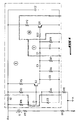
- the device of the invention can be realized, for example, according to the diagram represented on the figure 1 .
- the device comprises a measurement resistor R9 making it possible to measure a current flowing through a beam to be monitored.
- the device also comprises an amplifier circuit I which is intended to amplify current variations exceeding a predetermined threshold, which makes it possible to amplify only the large current variations, for example variations greater than 30 amperes / microsecond.
- the device of the invention then comprises a conditioning circuit II for transforming the profile of a measured current into a voltage representative of an energy to which the current corresponds, and a detector circuit III for detecting a level of energy. resulting from the anomaly and likely to cause a beam injury, including irreparable injury of the beam.
- the device of the invention finally comprises a signal generator making it possible to react to the anomaly observed, for example by generating an electric signal that can be used directly to power a control lamp or to actuate an acoustic alarm or a display means enabling for example, display the reference of the beam in which the anomaly was found.
- the filtering and the integration in the circuit makes it possible to eliminate current variations which originate from the normal operation of the electrical components of the vehicles, in particular at the time of starting or at the moment of the shutdown of an electrical component .
- the figure 2 shows the profile of a starter current with an amplitude of 1000 amperes, a rise time of 5 milliseconds, a descent time of 70 milliseconds and a settling time of 1 microsecond.
- the figure 3 represents an example of an impedance short circuit detected as a result of a beam injury with a current of 300 amps amplitude, a rise time of 50 microseconds, a descent time of 1 microsecond, a duration stabilization time of 10 microseconds and a period of 100 microseconds.
- the device of the invention thus makes it possible to detect through a parameterizable threshold, which is a function of the values of the resistors R12 and R22 of the circuit represented on the FIG. figure 1 , an energy level representing a beam injury.
- the device When the device detects a beam injury generating a strong impedance short-circuit, it can transmit the information to an optical or acoustic warning device installed for example on the dashboard of the motor vehicle. But it can also transmit this information to a centralized unit to inform the driver of the motor vehicle through a manager and information display of the vehicle so that the driver stops the vehicle in an emergency, just as the device can transmit the information also to the actuator for cutting the general power supply of the vehicle, especially when the span of the beam injury or multiple beams exceeds a predetermined value.
- a great advantage of the device of the invention is that it is entirely autonomous and in particular independent of all the vehicle components.
- the device of the invention provides protection of all the supply lines of a motor vehicle on all phases of life of the vehicle (park, storage, driving ).
- the device of the invention associated with a contactor, finally makes it possible to eliminate fuses whose effectiveness is not guaranteed or which are effective only in the presence of free short circuits or shocks occurring on the motor vehicle.
Landscapes
- Chemical & Material Sciences (AREA)
- Engineering & Computer Science (AREA)
- Combustion & Propulsion (AREA)
- Physics & Mathematics (AREA)
- General Physics & Mathematics (AREA)
- Testing Of Short-Circuits, Discontinuities, Leakage, Or Incorrect Line Connections (AREA)
- Emergency Protection Circuit Devices (AREA)
- Electric Propulsion And Braking For Vehicles (AREA)
Claims (7)
- Elektronische Vorrichtung, die es ermöglicht, Anomalien in Kabelbäumen eines Kraftfahrzeugs zu erfassen und diese Kabelbäume zu schützen, die einen Messwiderstand (R9), der es ermöglicht, einen Betriebsstrom zu messen, der durch einen zu überwachenden Kabelbaum geht, eine Verstärkerschaltung (I), die dazu bestimmt ist, Stromschwankungen zu verstärken, die einen vorbestimmten Schwellwert überschreiten, eine Konditionierungsschaltung (II), die dazu bestimmt ist, das Profil eines gemessenen Stroms in eine Spannung umzuwandeln, die für eine Energie repräsentativ ist, der der Strom entspricht, um Stromschwankungen zu unterdrücken, die als Ursprung den normalen Betrieb der elektrischen Organe des Fahrzeugs haben, und eine Detektorschaltung (III), die es ermöglicht, einen Energiepegel zu erfassen, der aus der Anomalie resultiert und eine Verletzung des Kabelbaums verursachen kann, sowie einen Signalgenerator aufweist, der es ermöglicht, auf die festgestellte Anomalie zu reagieren.
- Vorrichtung nach Anspruch 1, dadurch gekennzeichnet, dass die Umwandlung eines Profils eines gemessenen Stroms in eine Spannung, die für eine Energie repräsentativ ist, der der Strom entspricht, dazu bestimmt ist, durch Integration durchgeführt zu werden.
- Vorrichtung nach einem der Ansprüche 1 bis 2, dadurch gekennzeichnet, dass sie eine Lichtquelle aufweist, und dass der Signalgenerator mit der Lichtquelle verbunden ist.
- Vorrichtung nach einem der Ansprüche 1 bis 3, dadurch gekennzeichnet, dass der Signalgenerator einen Signalausgang aufweist, der es ermöglicht, die Vorrichtung mit einem Stellglied zu verbinden, das dazu bestimmt ist, die Stromversorgung zumindest in dem überwachten Kabelbaum zu unterbrechen.
- Vorrichtung nach einem der Ansprüche 1 bis 4, dadurch gekennzeichnet, dass der Signalgenerator einen Signalausgang aufweist, der es ermöglicht, die Vorrichtung mit einer elektronischen Steuer-und/oder Überwachungseinrichtung mindestens eines Teils der Funktionen zu verbinden, die in einem Kraftfahrzeug zur Verfügung stehen.
- Vorrichtung nach Anspruch 1, dadurch gekennzeichnet, dass der Signalgenerator einen Signalausgang aufweist, der es ermöglicht, die Vorrichtung mit einer Licht- oder Schallquelle zu verbinden.
- Kraftfahrzeug, dadurch gekennzeichnet, dass es eine Vorrichtung nach einem der Ansprüche 1 bis 6 aufweist.
Applications Claiming Priority (1)
| Application Number | Priority Date | Filing Date | Title |
|---|---|---|---|
| FR0553242A FR2892522B1 (fr) | 2005-10-25 | 2005-10-25 | Dispositif electronique pour detecter des anomalies dans des faisceaux electriques d'un vehicule automobile et vehicule automobile comportant un tel dispositif |
Publications (2)
| Publication Number | Publication Date |
|---|---|
| EP1780552A1 EP1780552A1 (de) | 2007-05-02 |
| EP1780552B1 true EP1780552B1 (de) | 2008-09-10 |
Family
ID=36603409
Family Applications (1)
| Application Number | Title | Priority Date | Filing Date |
|---|---|---|---|
| EP06301074A Not-in-force EP1780552B1 (de) | 2005-10-25 | 2006-10-23 | Elektronische Einrichtung zur Erkennung der Anomalien elektrischer Kabelbäume eines Fahrzeuges |
Country Status (4)
| Country | Link |
|---|---|
| EP (1) | EP1780552B1 (de) |
| AT (1) | ATE408148T1 (de) |
| DE (1) | DE602006002703D1 (de) |
| FR (1) | FR2892522B1 (de) |
Families Citing this family (1)
| Publication number | Priority date | Publication date | Assignee | Title |
|---|---|---|---|---|
| US9632125B2 (en) * | 2014-07-24 | 2017-04-25 | Ford Global Technologies, Llc | Harness anomaly detection systems and methods |
Family Cites Families (3)
| Publication number | Priority date | Publication date | Assignee | Title |
|---|---|---|---|---|
| US4684887A (en) * | 1986-06-24 | 1987-08-04 | General Battery Corporation | High voltage test confirmation apparatus |
| IT1293854B1 (it) * | 1997-06-25 | 1999-03-10 | Iveco Fiat | Dispositivo rilevatore di guasti lungo una linea elettrica di un veicolo, in particolare un veicolo industriale. |
| CA2369429C (en) * | 2001-01-25 | 2011-11-15 | Matsushita Electric Works, Ltd. | Method for discriminating abnormal current including arc current in ac load circuit and apparatus for executing the same |
-
2005
- 2005-10-25 FR FR0553242A patent/FR2892522B1/fr not_active Expired - Fee Related
-
2006
- 2006-10-23 EP EP06301074A patent/EP1780552B1/de not_active Not-in-force
- 2006-10-23 AT AT06301074T patent/ATE408148T1/de not_active IP Right Cessation
- 2006-10-23 DE DE602006002703T patent/DE602006002703D1/de active Active
Also Published As
| Publication number | Publication date |
|---|---|
| ATE408148T1 (de) | 2008-09-15 |
| DE602006002703D1 (de) | 2008-10-23 |
| EP1780552A1 (de) | 2007-05-02 |
| FR2892522A1 (fr) | 2007-04-27 |
| FR2892522B1 (fr) | 2007-12-14 |
Similar Documents
| Publication | Publication Date | Title |
|---|---|---|
| EP2053741B1 (de) | Selbstschützende elektrische Schaltvorrichtung | |
| FR3084468A1 (fr) | Procédé de diagnostic d’un moyen de commutation dans un véhicule automobile | |
| WO2015022329A1 (fr) | Dispositif de commutation et protection a distance de systemes electriques | |
| FR3088592A1 (fr) | Dispositif de securite pour circuit-electrique de vehicule | |
| EP3399612A1 (de) | Elektrischer anschluss, der eine elektrische schutzvorrichtung zur stromvorspannung umfasst | |
| EP0390698B1 (de) | Steuersystem für die elektrische Enteisung der Windschutzscheibe eines Kraftfahrzeugs durch Überspannung | |
| EP2088674B1 (de) | Regel und Schutzsystem für einen Low-Side Schalter einer Automatisierungseinrichtung | |
| EP1780552B1 (de) | Elektronische Einrichtung zur Erkennung der Anomalien elektrischer Kabelbäume eines Fahrzeuges | |
| EP0080425A1 (de) | Gerät zur Steuerung, Sicherung und Diagnose des elektrischen Netzes eines Kraftfahrzeugs | |
| EP2494564B1 (de) | System zur präventiven diagnose eines kontaktscheinwiderstands und von überlastungen eines umschalters | |
| FR2978324A1 (fr) | Dispositif electronique muni de moyens de coupure d'alimentation | |
| WO1999029007A1 (fr) | Dispositif de precharge d'un reseau electrique de puissance | |
| FR3067514B1 (fr) | Liaison electrique comprenant un dispositif de protection electrique - test d'integrite | |
| FR2978879A1 (fr) | Procede de diagnostic d'un court-circuit dans un ensemble electrique d'un vehicule automobile comprenant une composante capacitive et dispositif de diagnostic | |
| FR2889775A1 (fr) | Procede et montage de limitation de la dissipation d'un commutateur de puissance a semi-conducteur. | |
| EP2396665B1 (de) | Verfahren zum detektieren eines kurzschlusses und stromversorgungsmodul zum durchführen des verfahrens | |
| EP1764892A1 (de) | Vorrichtung zur Überwachung eines Fehlerstromes am Ausgang einer Energiequelle eines Kraftfahrzeuges | |
| FR2801441A1 (fr) | Dispositif ecreteur de surtensions pour un reseau de bord de vehicule, notamment automobile | |
| WO2020109375A1 (fr) | Dispositif de protection pour un circuit électrique et circuit électrique équipé d'un tel dispositif | |
| EP1544049A1 (de) | System zur Energieversorgung der funktionellen Elemente des Bordnetzes eines Kraftfahrzeuges | |
| EP2882094B1 (de) | Verfahren zum Ableiten der in einem Stator eines Elektromotors gespeicherten Energie | |
| EP1492210A1 (de) | Scutzsystem für zumindest eines Teils eines Kraftfahrzeugbordnetzes | |
| FR3097057A1 (fr) | Procédé de diagnostic de connexion électrique défaillante dans un système électrique | |
| WO2026027366A1 (fr) | Procédé de protection d'une branche de circuit électrique d'un véhicule automobile | |
| FR2947111A1 (fr) | Circuit electrique |
Legal Events
| Date | Code | Title | Description |
|---|---|---|---|
| PUAI | Public reference made under article 153(3) epc to a published international application that has entered the european phase |
Free format text: ORIGINAL CODE: 0009012 |
|
| AK | Designated contracting states |
Kind code of ref document: A1 Designated state(s): AT BE BG CH CY CZ DE DK EE ES FI FR GB GR HU IE IS IT LI LT LU LV MC NL PL PT RO SE SI SK TR |
|
| AX | Request for extension of the european patent |
Extension state: AL BA HR MK YU |
|
| 17P | Request for examination filed |
Effective date: 20071010 |
|
| 17Q | First examination report despatched |
Effective date: 20071105 |
|
| AKX | Designation fees paid |
Designated state(s): AT BE BG CH CY CZ DE DK EE ES FI FR GB GR HU IE IS IT LI LT LU LV MC NL PL PT RO SE SI SK TR |
|
| GRAP | Despatch of communication of intention to grant a patent |
Free format text: ORIGINAL CODE: EPIDOSNIGR1 |
|
| GRAS | Grant fee paid |
Free format text: ORIGINAL CODE: EPIDOSNIGR3 |
|
| GRAA | (expected) grant |
Free format text: ORIGINAL CODE: 0009210 |
|
| AK | Designated contracting states |
Kind code of ref document: B1 Designated state(s): AT BE BG CH CY CZ DE DK EE ES FI FR GB GR HU IE IS IT LI LT LU LV MC NL PL PT RO SE SI SK TR |
|
| REG | Reference to a national code |
Ref country code: GB Ref legal event code: FG4D Free format text: NOT ENGLISH |
|
| REG | Reference to a national code |
Ref country code: CH Ref legal event code: EP |
|
| REG | Reference to a national code |
Ref country code: IE Ref legal event code: FG4D Free format text: LANGUAGE OF EP DOCUMENT: FRENCH |
|
| REF | Corresponds to: |
Ref document number: 602006002703 Country of ref document: DE Date of ref document: 20081023 Kind code of ref document: P |
|
| REG | Reference to a national code |
Ref country code: GB Ref legal event code: 746 Effective date: 20081222 |
|
| PG25 | Lapsed in a contracting state [announced via postgrant information from national office to epo] |
Ref country code: LT Free format text: LAPSE BECAUSE OF FAILURE TO SUBMIT A TRANSLATION OF THE DESCRIPTION OR TO PAY THE FEE WITHIN THE PRESCRIBED TIME-LIMIT Effective date: 20080910 |
|
| PG25 | Lapsed in a contracting state [announced via postgrant information from national office to epo] |
Ref country code: AT Free format text: LAPSE BECAUSE OF FAILURE TO SUBMIT A TRANSLATION OF THE DESCRIPTION OR TO PAY THE FEE WITHIN THE PRESCRIBED TIME-LIMIT Effective date: 20080910 Ref country code: SI Free format text: LAPSE BECAUSE OF FAILURE TO SUBMIT A TRANSLATION OF THE DESCRIPTION OR TO PAY THE FEE WITHIN THE PRESCRIBED TIME-LIMIT Effective date: 20080910 Ref country code: LV Free format text: LAPSE BECAUSE OF FAILURE TO SUBMIT A TRANSLATION OF THE DESCRIPTION OR TO PAY THE FEE WITHIN THE PRESCRIBED TIME-LIMIT Effective date: 20080910 Ref country code: FI Free format text: LAPSE BECAUSE OF FAILURE TO SUBMIT A TRANSLATION OF THE DESCRIPTION OR TO PAY THE FEE WITHIN THE PRESCRIBED TIME-LIMIT Effective date: 20080910 |
|
| NLV1 | Nl: lapsed or annulled due to failure to fulfill the requirements of art. 29p and 29m of the patents act | ||
| REG | Reference to a national code |
Ref country code: IE Ref legal event code: FD4D |
|
| BERE | Be: lapsed |
Owner name: PEUGEOT CITROEN AUTOMOBILES SA Effective date: 20081031 |
|
| PG25 | Lapsed in a contracting state [announced via postgrant information from national office to epo] |
Ref country code: ES Free format text: LAPSE BECAUSE OF FAILURE TO SUBMIT A TRANSLATION OF THE DESCRIPTION OR TO PAY THE FEE WITHIN THE PRESCRIBED TIME-LIMIT Effective date: 20081221 Ref country code: BG Free format text: LAPSE BECAUSE OF FAILURE TO SUBMIT A TRANSLATION OF THE DESCRIPTION OR TO PAY THE FEE WITHIN THE PRESCRIBED TIME-LIMIT Effective date: 20081210 Ref country code: IE Free format text: LAPSE BECAUSE OF FAILURE TO SUBMIT A TRANSLATION OF THE DESCRIPTION OR TO PAY THE FEE WITHIN THE PRESCRIBED TIME-LIMIT Effective date: 20080910 |
|
| PG25 | Lapsed in a contracting state [announced via postgrant information from national office to epo] |
Ref country code: CZ Free format text: LAPSE BECAUSE OF FAILURE TO SUBMIT A TRANSLATION OF THE DESCRIPTION OR TO PAY THE FEE WITHIN THE PRESCRIBED TIME-LIMIT Effective date: 20080910 Ref country code: IS Free format text: LAPSE BECAUSE OF FAILURE TO SUBMIT A TRANSLATION OF THE DESCRIPTION OR TO PAY THE FEE WITHIN THE PRESCRIBED TIME-LIMIT Effective date: 20090110 Ref country code: PT Free format text: LAPSE BECAUSE OF FAILURE TO SUBMIT A TRANSLATION OF THE DESCRIPTION OR TO PAY THE FEE WITHIN THE PRESCRIBED TIME-LIMIT Effective date: 20090210 Ref country code: RO Free format text: LAPSE BECAUSE OF FAILURE TO SUBMIT A TRANSLATION OF THE DESCRIPTION OR TO PAY THE FEE WITHIN THE PRESCRIBED TIME-LIMIT Effective date: 20080910 Ref country code: SK Free format text: LAPSE BECAUSE OF FAILURE TO SUBMIT A TRANSLATION OF THE DESCRIPTION OR TO PAY THE FEE WITHIN THE PRESCRIBED TIME-LIMIT Effective date: 20080910 Ref country code: MC Free format text: LAPSE BECAUSE OF NON-PAYMENT OF DUE FEES Effective date: 20081031 Ref country code: NL Free format text: LAPSE BECAUSE OF FAILURE TO SUBMIT A TRANSLATION OF THE DESCRIPTION OR TO PAY THE FEE WITHIN THE PRESCRIBED TIME-LIMIT Effective date: 20080910 |
|
| PLBE | No opposition filed within time limit |
Free format text: ORIGINAL CODE: 0009261 |
|
| STAA | Information on the status of an ep patent application or granted ep patent |
Free format text: STATUS: NO OPPOSITION FILED WITHIN TIME LIMIT |
|
| PG25 | Lapsed in a contracting state [announced via postgrant information from national office to epo] |
Ref country code: DK Free format text: LAPSE BECAUSE OF FAILURE TO SUBMIT A TRANSLATION OF THE DESCRIPTION OR TO PAY THE FEE WITHIN THE PRESCRIBED TIME-LIMIT Effective date: 20080910 Ref country code: EE Free format text: LAPSE BECAUSE OF FAILURE TO SUBMIT A TRANSLATION OF THE DESCRIPTION OR TO PAY THE FEE WITHIN THE PRESCRIBED TIME-LIMIT Effective date: 20080910 |
|
| 26N | No opposition filed |
Effective date: 20090611 |
|
| PG25 | Lapsed in a contracting state [announced via postgrant information from national office to epo] |
Ref country code: IT Free format text: LAPSE BECAUSE OF FAILURE TO SUBMIT A TRANSLATION OF THE DESCRIPTION OR TO PAY THE FEE WITHIN THE PRESCRIBED TIME-LIMIT Effective date: 20080910 |
|
| PG25 | Lapsed in a contracting state [announced via postgrant information from national office to epo] |
Ref country code: BE Free format text: LAPSE BECAUSE OF NON-PAYMENT OF DUE FEES Effective date: 20081031 |
|
| PG25 | Lapsed in a contracting state [announced via postgrant information from national office to epo] |
Ref country code: SE Free format text: LAPSE BECAUSE OF FAILURE TO SUBMIT A TRANSLATION OF THE DESCRIPTION OR TO PAY THE FEE WITHIN THE PRESCRIBED TIME-LIMIT Effective date: 20081210 |
|
| PG25 | Lapsed in a contracting state [announced via postgrant information from national office to epo] |
Ref country code: PL Free format text: LAPSE BECAUSE OF FAILURE TO SUBMIT A TRANSLATION OF THE DESCRIPTION OR TO PAY THE FEE WITHIN THE PRESCRIBED TIME-LIMIT Effective date: 20080910 |
|
| PG25 | Lapsed in a contracting state [announced via postgrant information from national office to epo] |
Ref country code: HU Free format text: LAPSE BECAUSE OF FAILURE TO SUBMIT A TRANSLATION OF THE DESCRIPTION OR TO PAY THE FEE WITHIN THE PRESCRIBED TIME-LIMIT Effective date: 20090311 Ref country code: CY Free format text: LAPSE BECAUSE OF FAILURE TO SUBMIT A TRANSLATION OF THE DESCRIPTION OR TO PAY THE FEE WITHIN THE PRESCRIBED TIME-LIMIT Effective date: 20080910 Ref country code: LU Free format text: LAPSE BECAUSE OF NON-PAYMENT OF DUE FEES Effective date: 20081023 |
|
| PG25 | Lapsed in a contracting state [announced via postgrant information from national office to epo] |
Ref country code: TR Free format text: LAPSE BECAUSE OF FAILURE TO SUBMIT A TRANSLATION OF THE DESCRIPTION OR TO PAY THE FEE WITHIN THE PRESCRIBED TIME-LIMIT Effective date: 20080910 |
|
| PG25 | Lapsed in a contracting state [announced via postgrant information from national office to epo] |
Ref country code: GR Free format text: LAPSE BECAUSE OF FAILURE TO SUBMIT A TRANSLATION OF THE DESCRIPTION OR TO PAY THE FEE WITHIN THE PRESCRIBED TIME-LIMIT Effective date: 20081211 |
|
| REG | Reference to a national code |
Ref country code: CH Ref legal event code: PL |
|
| PG25 | Lapsed in a contracting state [announced via postgrant information from national office to epo] |
Ref country code: CH Free format text: LAPSE BECAUSE OF NON-PAYMENT OF DUE FEES Effective date: 20101031 Ref country code: LI Free format text: LAPSE BECAUSE OF NON-PAYMENT OF DUE FEES Effective date: 20101031 |
|
| REG | Reference to a national code |
Ref country code: FR Ref legal event code: PLFP Year of fee payment: 11 |
|
| REG | Reference to a national code |
Ref country code: FR Ref legal event code: PLFP Year of fee payment: 12 |
|
| REG | Reference to a national code |
Ref country code: FR Ref legal event code: CA Effective date: 20180312 Ref country code: FR Ref legal event code: CD Owner name: PEUGEOT CITROEN AUTOMOBILES SA, FR Effective date: 20180312 |
|
| REG | Reference to a national code |
Ref country code: FR Ref legal event code: PLFP Year of fee payment: 13 |
|
| PGFP | Annual fee paid to national office [announced via postgrant information from national office to epo] |
Ref country code: FR Payment date: 20190919 Year of fee payment: 14 |
|
| PGFP | Annual fee paid to national office [announced via postgrant information from national office to epo] |
Ref country code: GB Payment date: 20190923 Year of fee payment: 14 |
|
| PGFP | Annual fee paid to national office [announced via postgrant information from national office to epo] |
Ref country code: DE Payment date: 20190918 Year of fee payment: 14 |
|
| REG | Reference to a national code |
Ref country code: DE Ref legal event code: R119 Ref document number: 602006002703 Country of ref document: DE |
|
| GBPC | Gb: european patent ceased through non-payment of renewal fee |
Effective date: 20201023 |
|
| PG25 | Lapsed in a contracting state [announced via postgrant information from national office to epo] |
Ref country code: FR Free format text: LAPSE BECAUSE OF NON-PAYMENT OF DUE FEES Effective date: 20201031 Ref country code: DE Free format text: LAPSE BECAUSE OF NON-PAYMENT OF DUE FEES Effective date: 20210501 |
|
| PG25 | Lapsed in a contracting state [announced via postgrant information from national office to epo] |
Ref country code: GB Free format text: LAPSE BECAUSE OF NON-PAYMENT OF DUE FEES Effective date: 20201023 |