EP1780481A2 - Verfahren zur Herstellung von Kunstschnee sowie Schneekanone zur Durchführung des Verfahrens - Google Patents
Verfahren zur Herstellung von Kunstschnee sowie Schneekanone zur Durchführung des Verfahrens Download PDFInfo
- Publication number
- EP1780481A2 EP1780481A2 EP05023743A EP05023743A EP1780481A2 EP 1780481 A2 EP1780481 A2 EP 1780481A2 EP 05023743 A EP05023743 A EP 05023743A EP 05023743 A EP05023743 A EP 05023743A EP 1780481 A2 EP1780481 A2 EP 1780481A2
- Authority
- EP
- European Patent Office
- Prior art keywords
- snow
- water
- carbon dioxide
- blown
- heat
- Prior art date
- Legal status (The legal status is an assumption and is not a legal conclusion. Google has not performed a legal analysis and makes no representation as to the accuracy of the status listed.)
- Granted
Links
Images

Classifications
-
- F—MECHANICAL ENGINEERING; LIGHTING; HEATING; WEAPONS; BLASTING
- F25—REFRIGERATION OR COOLING; COMBINED HEATING AND REFRIGERATION SYSTEMS; HEAT PUMP SYSTEMS; MANUFACTURE OR STORAGE OF ICE; LIQUEFACTION SOLIDIFICATION OF GASES
- F25C—PRODUCING, WORKING OR HANDLING ICE
- F25C3/00—Processes or apparatus specially adapted for producing ice or snow for winter sports or similar recreational purposes, e.g. for sporting installations; Producing artificial snow
- F25C3/04—Processes or apparatus specially adapted for producing ice or snow for winter sports or similar recreational purposes, e.g. for sporting installations; Producing artificial snow for sledging or ski trails; Producing artificial snow
-
- C—CHEMISTRY; METALLURGY
- C01—INORGANIC CHEMISTRY
- C01B—NON-METALLIC ELEMENTS; COMPOUNDS THEREOF; METALLOIDS OR COMPOUNDS THEREOF NOT COVERED BY SUBCLASS C01C
- C01B32/00—Carbon; Compounds thereof
- C01B32/50—Carbon dioxide
- C01B32/55—Solidifying
-
- F—MECHANICAL ENGINEERING; LIGHTING; HEATING; WEAPONS; BLASTING
- F25—REFRIGERATION OR COOLING; COMBINED HEATING AND REFRIGERATION SYSTEMS; HEAT PUMP SYSTEMS; MANUFACTURE OR STORAGE OF ICE; LIQUEFACTION SOLIDIFICATION OF GASES
- F25C—PRODUCING, WORKING OR HANDLING ICE
- F25C2303/00—Special arrangements or features for producing ice or snow for winter sports or similar recreational purposes, e.g. for sporting installations; Special arrangements or features for producing artificial snow
- F25C2303/044—Snow making using additional features, e.g. additives, liquid gas
-
- F—MECHANICAL ENGINEERING; LIGHTING; HEATING; WEAPONS; BLASTING
- F25—REFRIGERATION OR COOLING; COMBINED HEATING AND REFRIGERATION SYSTEMS; HEAT PUMP SYSTEMS; MANUFACTURE OR STORAGE OF ICE; LIQUEFACTION SOLIDIFICATION OF GASES
- F25D—REFRIGERATORS; COLD ROOMS; ICE-BOXES; COOLING OR FREEZING APPARATUS NOT OTHERWISE PROVIDED FOR
- F25D3/00—Devices using other cold materials; Devices using cold-storage bodies
- F25D3/12—Devices using other cold materials; Devices using cold-storage bodies using solidified gases, e.g. carbon-dioxide snow
Definitions
- Natural snow consists of tiny, spatially branched ice crystals that grow very rapidly along the hexagonal crystal directions that lie in the base plane of the hexagonal crystal lattice.
- the melting point of ice is 0 ° C.
- heat of fusion must be supplied.
- FIG. 1 A typical temperature-time diagram for the cooling of water is shown in FIG.
- ⁇ T a certain subcooling, below the melting temperature is necessary.
- the quantity of heat ⁇ Q (in Ws) flows in the time interval ⁇ t (in s) in proportion to the temperature gradient ⁇ T / ⁇ x:
- ⁇ Q ⁇ t - ⁇ ⁇ A ⁇ ⁇ T ⁇ x
- ⁇ is the thermal conductivity (in WK -1 m -1 )
- A is the area that flows through (in m 2 )
- ⁇ T is the subcooling (in K)
- ⁇ x is the traversed path (in m). That is, without hypothermia there is no heat flow.
- the subcooling of the liquid water is also promoted by its observed inertia for crystallization.
- the reason for this is probably that the water already has a very similar lattice structure (glass structure) to the solid phase and the transport of atoms (diffusion) becomes more difficult at lower temperatures.
- An approximately 1 l volume of water shows subcooling down to temperatures around -10 ° C. Smaller quantities of water (tenth of a gram range) can be subcooled to -33 ° C, even smaller amounts down to -70 ° C (1). This crystallization without foreign crystals is called homogeneous crystallization.
- phase diagram you can see essentially 3 strong lines leading to the triple point. They limit the phase ranges solid phase, liquid phase and gaseous phase as a function of temperature and pressure. There are 2 phases in equilibrium along these lines. Only one variable, temperature or pressure can be changed along these lines. The other one automatically adjusts.
- the equilibrium line between the liquid and gaseous phase one finds the state which prevails in the bottled gas. That's about 62 bar at 25 ° C. If the liquid gas is now evaporated very slowly, so that the necessary heat for the expansion of the gas can be supplied from the outside (isothermal expansion), then the pressure of 62 bar in the gas cylinder is maintained as long as liquid phase is present. Only after the evaporation of the last liquid gas molecule can the pressure drop to the ambient pressure.
- 1 mol CO 2 is cooled by adiabatic expansion to - 80 ° C and at the same time 1 mol H 2 O because of poor heat transfer only to - 27 ° C, no phase transformations.
- the heat released when the water cools from 0 to - 27 ° C can heat the CO 2 gas from - 80 ° C to - 27 ° C.
- CO 2 snow exists at about -79 ° C until the last molecule of this solid phase has evaporated. Due to the high heat of vaporization of CO 2 - snow (25218 joule / mol) and its poor thermal conductivity, it is also relatively stable.
- CO 2 dry ice squeezed CO 2 - Snow days can be stored at room temperature. With a mixture of ether + CO 2 - snow you can set a cooling bath of - 100 ° C. In order to heat the evaporating gas from -79.2 to 0 ° C, an additional 3021 joules / mol would be required. Thus, 1 mol CO 2 snow 4.7 mol, ie almost 5 mol of H 2 O remove the heat of fusion.
- CO 2 - snow as a crystallization nucleus of H 2 O are the atomic structure and the morphology of the two crystal lattices.
- the atomic structure of CO 2 is based on CO 4 tetrahedra, that of H 2 O on H 4 O tetrahedra.
- CO 2 therefore not only acts as a heterogeneous nucleator, but also as a quasi-homogeneous one. Due to its flake-like habit, the CO 2 snow can stimulate the water droplets to form flocs. After crystallization, the solid CO 2 evaporates without leaving residues in the atmosphere from which it was originally taken. Because of the great coldness of the CO 2 crystals, they also do not react chemically with water.
- the idea of this invention is now to inject liquid CO 2 or a mixture of liquid and gaseous CO 2 not in the high pressure area of the H 2 O - atomization space, but with the CO 2 - liquefied petroleum gas or LPG vapor mixture in its own thermally separated, isolated water- and gas-tight expander, unaffected by H 2 O atomization, secured CO 2 - snow to produce and then blown on its own thermally insulated line in the area of the air - water mist with the highest supercooling.
- the optimal injection point or the optimal injection points are to be determined experimentally on a case-by-case basis.
- the solution to produce CO 2 - snow on-site from LPG seems to be the most practicable today.
- CO 2 snow could also be produced centrally and transported via their own insulated lines to the snow machines.
- liquefied gas can also be brought to the respective expander either from bottles or via a line from a central supply point (see FIG. 3).
- the expander system for CO 2 snow production can be integrated into existing snow machines or constructions of new snow machines (see claim 3) or built as a standalone unit and provided to the existing snow machines.
- the water to be atomized should not be cryogenically cooled.
- the cryogenic effect here is limited to the droplet in which the crystallization is to be stimulated.
- the increase in CO 2 concentration of the generated H 2 O snow caused by the method described here should be below 1 ppm.
Landscapes
- Chemical & Material Sciences (AREA)
- Engineering & Computer Science (AREA)
- Organic Chemistry (AREA)
- Physics & Mathematics (AREA)
- Mechanical Engineering (AREA)
- Thermal Sciences (AREA)
- General Engineering & Computer Science (AREA)
- Chemical Kinetics & Catalysis (AREA)
- Inorganic Chemistry (AREA)
- Physical Or Chemical Processes And Apparatus (AREA)
- Organic Low-Molecular-Weight Compounds And Preparation Thereof (AREA)
- Carbon And Carbon Compounds (AREA)
Abstract
Description
- Natürlicher Schnee besteht aus winzigen, räumlich verzweigten Eiskristallen, die entlang der hexagonalen Kristallrichtungen, die in der Basisebene des hexagonalen Kristallgitters liegen, sehr schnell gewachsen sind. Der Schmelzpunkt von Eis liegt bei 0°C. Zum Schmelzen von Eis muss Schmelzwärme zugeführt werden. Umgekehrt muss bei der Kristallisation von
- Eis und Schnee aus Regentropfen oder Wasser diese Schmelzwärme wieder abgeführt werden.
- Ein typisches Temperatur - Zeitdiagramm für die Abkühlung von Wasser ist in Figur 1 dargestellt. Zum Abtransport der Schmelzwärme ist eine gewisse Unterkühlung, ΔT, unter die Schmelztemperatur notwendig. Nach dem ersten Fourierschen Gesetz fließt die Wärmemenge ΔQ (in Ws) im Zeitintervall Δt (in s) proportional zum Temperaturgradienten ΔT/Δx:

- Darin sind λ die Wärmeleitfähigkeit (in WK-1m-1), A die durchflossene Fläche (in m2), ΔT die Unterkühlung (in K) und Δx der durchflossene Weg (in m). Das heißt, ohne Unterkühlung gibt es keinen Wärmeabfluss.
- Kristallisiert dann ein Teil des Volumens des Wassers aus, dann führt die freigesetzte Wärme wieder zur Erwärmung des noch nicht kristallisierten Wassers. Da nur bei der Schmelztemperatur festes und flüssiges Wasser im thermodynamischen Gleichgewicht sind, führt eine Überschreitung der Schmelztemperatur zum Wiederaufschmelzen des bereits gebildeten Eises. Dies drückt sich in der Ausbildung eines Plateaus in der Abkühlkurve aus.
- Die Unterkühlung des flüssigen Wassers wird aber auch durch seine beobachtete Trägheit zur Kristallisation gefördert. Der Grund dafür liegt wahrscheinlich darin, dass das Wasser ohnehin schon eine der festen Phase sehr ähnliche Gitterstruktur (Glasstruktur) besitzt und der Transport von Atomen (Diffusion) bei tieferen Temperaturen immer schwieriger wird. Ein etwa 1I Wasservolumen zeigt Unterkühlungen bis zu Temperaturen um -10°C. Kleinere Wassermengen (Zehntelgrammbereich) lassen sich bis -33°C, noch kleinere Mengen bis -70°C unterkühlen (1). Diese Kristallisation ohne Fremdkristalle wird als homogene Kristallisation bezeichnet.
- Die Anwesenheit von kleinen sub-mikroskopischen Kernen fördert die Kristallisation und erhöht die Kristallisationstemperatur. In der Natur führt das dazu, dass die vorhandenen kristallinen Gefrierkerne (Staubteilchen) die Schneebildung bei etwa -4°C bewirken. Die Kristallisation mit Hilfe von winzigen fremden Kristallen bezeichnet man als heterogene Kristallisation.
- Es gibt noch eine Methode der Einbringung von Kristallisationskeimen in das unterkühlte Wasser, die darin besteht, Pulver aus H2O - Eiskristallen einzublasen. Dies wäre dann Kristallisation mit Hilfe der Epitaxie, bei der der Samenkristall die selbe Struktur hat wie der ausgewachsene Kristall.
- Die Produktion von künstlichem Schnee mittels Schneemaschinen aus natürlichem Wasser ohne künstliche Zusätze ist erst, abhängig von der relativen Luftfeuchtigkeit bei Temperaturen unter -4°C möglich. Eine Zusammenfassung der verschiedenen Methoden der Herstellung von künstlichem Schnee, einschließlich kryogener Methoden findet man in einem Buch von H. Fuhrmann (2).
- Zur Zeit gibt es noch keine umweltfreundliche Methode, die Schneebildung zu Temperaturen über -4°C zu verschieben.
- Für die kryogene Herstellung von Kunstschnee (2) werden hauptsächlich die verflüssigten Gase N2 und CO2 eingesetzt. Da CO2 preiswert ist und außerdem noch für die Kunstschneebildung interessante Eigenschaften hat, sollen diese Eigenschaften anhand eines Phasendiagrammes von CO2 (siehe Figur 2) diskutiert werden.
- In diesem Phasendiagramm sieht man im wesentlichen 3 starke Linien, die zum Tripelpunkt führen. Sie begrenzen die Phasenbereiche feste Phase, flüssige Phase und gasförmige Phase als Funktion von Temperatur und Druck. Entlang dieser Linien sind jeweils 2 Phasen im Gleichgewicht. Es kann entlang dieser Linien nur eine Variable, Temperatur oder Druck verändert werden. Die andere stellt sich automatisch ein.
- Verfolgt man zum Beispiel die Gleichgewichtslinie zwischen der flüssigen und gasförmigen Phase, findet man den Zustand, der im Flaschengas herrscht. Das sind etwa 62 bar bei 25°C. Verdampft man nun das flüssige Gas sehr langsam, so dass die notwendige Wärme für die Ausdehnung des Gases von außen zugeführt werden kann (isotherme Ausdehnung), dann bleibt der Druck von 62 bar in der Gasflasche so lange erhalten, wie Flüssigphase vorhanden ist. Erst nach dem Verdampfen des letzten Flüssiggasmoleküls kann der Druck auf den Umgebungsdruck abfallen.
- Gibt es keine Wärmezufuhr (adiabatische Bedingung) bei der Entspannung, dann kühlt sich das Gemisch aus flüssigem und gasförmigen CO2 zunächst bis zum Tripelpunkt (-56,6 °C, 5,2 bar) ab. Bei diesem Punkt sind die drei Phasen Flüssigphase, Festphase und Gasphase im Gleichgewicht. Es gibt keinem Freiheitsgrad mehr. Druck und Volumen sind fixiert. Bei dieser Temperatur verharrt das Gas beim weiteren Entspannen, bis das Flüssiggas vollständig verdampft ist. Bei der noch weiteren Entspannung bis auf Atmosphärendruck steht das CO2 - Gas mit CO2 - Festphase (CO2 - Schnee) im Gleichgewicht und kühlt sich bis zum Erreichen des Atmosphärendruckes von 1 bar auf -79,2 °C ab. Es kondensiert der CO2 - Schnee direkt aus der Gasphase.
- Wird dem Gas jedoch bei der Entspannung Wärme zugeführt, aber nicht genug, um den isothermen Zustand zu erreichen, dann liegt der Entspannungsweg irgendwo zwischen Adiabate und Isotherme. Man nennt das polytrope Entspannung.
- Es gibt Patentanmeldungen (3,4) über Schneemaschinen, bei denen flüssiges CO2 direkt in eine Zerstäuberkammer (Hochdruckbereich des Wasser - Luftgemisches) eingespritzt wird. Eine andere benutzt eine Vorkammer (5), die allerdings erfindungsgemäß im thermischen Kontakt mit dem zu versprühenden Wasser steht Das expandierende Gemisch aus flüssigem CO2 und CO2 - Gas wird von der Vorkammer aus in den unmittelbar angrenzenden Hochdruckbereich der Zerstäuberdüsen eingeblasen. Dabei soll das zu versprühende Wasser gekühlt werden, in dem es seine Wärme an das CO2-Flüssiggas-Gasgemisch abgibt.
- Die Bildung von CO2 - Schnee nach den oben erwähnten Verfahren ist aus zwei Gründen unwahrscheinlich:
- In Gegenwart von Wasser, wird diesem bei der Abkühlung durch das sich ausdehnende CO2 Wärme entzogen und dem CO2 - Gas zugeführt. Dadurch wird die für die CO2 - Schneebildung notwendige adiabatische Abkühlung auf -79,2 °C verhindert. Zur quantitativen Abschätzung der Wärmegleichgewichte zwischen H2O und CO2 wird eine einfache Wärmebilanz durchgeführt:
- 1 Mol CO2 sei durch adiabatische Expansion auf - 80 °C abgekühlt und gleichzeitig 1 Mol H2O wegen der schlechten Wärmeübertragung nur auf - 27 °C, keine Phasenumwandlungen.
- Die beim Abkühlen des Wassers von 0 auf - 27°C frei werdende Wärme kann das CO2 - Gas von - 80 °C auf - 27 °C erwärmen.
- Bei dieser Rechnung ist die bei einer eventuellen Kristallisation frei werdende Schmelzwärme von Wassereis von 6012 J/mol noch nicht berücksichtigt.
- Würde die Schmelzwärme mitberücksichtigt, dann würde diese Wärmemenge ausreichen, um das CO2 auf +26°C zu erwärmen.
- Diese Rechnung zeigt, dass das Wasser eine Wärmequelle ist, die die Bildung von festen CO2 - Kristallen unwahrscheinlich macht.
- Es ist aus der Chemie bekannt (6), dass CO2 mit H2O zu Kohlensäure reagiert.
- Welche Spezies und welche Wärmemengen (positiv oder negativ) entstehen, wenn 1 Mol CO2 (300 K, 59 bar) mit H2O(300K, 1 bar) reagiert?
- Die Berechnung wurde mit Hilfe des Programmpaketes CHEMSAGE der Fa. GTT TECHNOLOGIES (7) durchgeführt.
T = 300.00 κ P = 5.90000E+01 bar V = 4.07863E-01 dm3 STREAM CONSTITUENTS AMOUNT/mol CO2/GAS/ 1.0000E+00 H2O/AQUEOUS/ 1.0000E+00 PHASE: GAS EQUIL AMOUNT mol MOLE FRACTION FUGACITY bar CO2 T 9.6422E-01 9.9947E-01 5.8969E+01 H2O T 5.1004E-04 5.2868E-04 3.1192E-02 H2 T 5.9443E-30 6.1616E-30 3.6354E-28 02 T 3.0304E-30 3.1412E-30 1.8533E-28 CO T 1.1645E-31 1.2071E-31 7.1218E-30 TOTAL: 9.6473E-01 1.0000E+00 1.0000E+00 PHASE: AQUEOUS mol MOLALITY ACTIVITY H2O T 9.9947E-01 5.5508E+01 9.6482E-01 H<+> T 1.8336E-05 1.0183E-03 9.8178E-04 OH<-> T 2.2557E-13 1.2528E-11 1.2080E-11 HCO3<-> T 1.8336E-05 1.0183E-03 9.6178E-04 C03<2-> T 1.1101E-12 6.1654E-11 5.3028E-11 CO2(AQ) T 3.5757E-02 1.9859E+00 1.9859E+00 TOTAL: 1.0353E+00 1.0000E+00 Cp_EQUIL J.K-1 H_EQUIL J S_EQUIL J.K-1 G_EQUIL J V_EQUIL dm3 1.88366E-05 -6.31224E+05 -3.25751E+01 -6.21451E+05 4.07863E-01 pH = 3.0080 Eh/V = 0.6376 Total solute molality = 1.9879 Ionic strength = 0.0010 Osmotic coefficient = 1.0000 Debye-Hueckel slope = 0.3916 Mole fraction of the system components: GAS AQUEOUS C 3.3316E-01 1.1519E-02 O 6.6649E-01 3.4485E-01 H 3.5245E-04 6.4363E-01 Data on 11 constituents marked with 'T' are extrapolated outside their valid temperature range T = 300.00 κ P = 5.90000E+01 bar V = 4.07863E-01 dm3 STREAM CONSTITUENTS AMOUNT/mol CO2/GAS/ 1.0000E+00 H2O/AQUEOUS/ 1.0000E+00 PHASE: GAS EQUIL AMOUNT mol MOLE FRACTION FUGACITY bar CO2 T 9.6422E-01 9.9947E-01 5.8969E+01 H2O T 5.1004E-04 5.2868E-04 3.1192E-02 H2 T 5.9443E-30 6.1616E-30 3.6354E-28 O2 T 3.0304E-30 3.1412E-30 1.8533E-28 CO T 1.1645E-31 1.2071E-31 7.1218E-30 H<+> - Ionen =1,8336 10-5 mol HCO3 <-> - Ionen = 1,8336 10-5 mol CO2(AQ) in Wasser gelöstes Kohlendioxid = 3,575 10-2 mol
Schließlich kann man aus der bei dieser Reaktion entstehende Masse an H<+> - Ionen von 1,8336 x 10⁻⁵ mol einen pH - Wert von ungefähr 3 errechnen. - Ein Prozess, der eine so starke Säure produziert, dürfte kaum genehmigungsfähig sein. Dies steht im krassen Gegensatz zu dem in dieser Arbeit vorgestellten Verfahren (Hofer-Snow), bei dem die Menge an eingebrachtem CO2 im Verhältnis zur Gesamtmenge an H2O verschwindend gering ist.
- Wie bereits angedeutet, existiert CO2 - Schnee bei etwa -79 °C solange, bis das letzte Molekül dieser Festphase verdampft ist. Wegen der hohen Verdampfungswärme von CO2 - Schnee (25218 joule/mol) und seiner schlechten Wärmeleitfähigkeit ist er auch verhältnismäßig stabil. Zu CO2Trockeneis gepresster CO2 - Schnee kann tagelang bei Raumtemperatur lagern. Mit einer Mischung aus Äther + CO2 - Schnee kann man ein Kältebad von - 100 °C einstellen. Um das verdampfende Gas von -79,2 auf 0 °C zu erwärmen, wären noch zusätzlich 3021 joule/mol erforderlich. Damit könnte 1 mol CO2 -Schnee 4,7 mol, d.h. fast 5 mol H2O die Schmelzwärme entziehen. Weitere Gründe für die Eignung von CO2 - Schnee als Kristallisationskeim von H2O liegen in der Atomstruktur und der Morphologie der beiden Kristallgitter. Die Atomstruktur von CO2 basiert auf CO4 - Tetraedern, die von H2O auf H4O-Tetraedern. CO2 wirkt daher nicht nur als heterogener Keimbildner, sondern auch als quasi - homogener. Durch seinen flockenförmigen Habitus kann der CO2-Schnee die Wassertröpfchen zur Flockenbildung anregen. Nach der Kristallisation verdampft das feste CO2 ohne Rückstände in Atmosphäre, aus der es ursprünglich entnommen wurde. Wegen der großen Kälte der CO2 - Kristalle reagieren sie auch chemisch praktisch nicht mit dem Wasser.
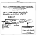
- Die Idee dieser Erfindung liegt nun darin, flüssiges CO2 oder ein Gemisch aus flüssigem und gasförmigem CO2 nicht in den Hochdruckbereich des H2O - Zerstäubungsraumes einzuspritzen, sondern mit dem CO2 - Flüssiggas oder Flüssiggas -Dampfgemisch in einem eigenen thermisch getrennten, isolierten wasser- und gasdichten Expander, unbeeinflusst von der H2O - Zerstäubung, gesichert CO2 - Schnee zu erzeugen und dann über eine eigene thermisch isolierte Leitung in den Bereich des Luft - Wassernebels mit der höchsten Unterkühlung einzublasen. Der optimale Einblaspunkt oder die optimalen Einblaspunkte sind von Fall zu Fall experimentell zu bestimmen. Die Lösung, CO2 - Schnee vor Ort aus Flüssiggas zu erzeugen, scheint heute die praktikabelste zu sein. Prinzipiell könnte CO2 - Schnee auch zentral hergestellt und über eigene isolierte Leitungen zu den Schneemaschinen transportiert werden. Flüssiggas kann übrigens auch entweder aus Flaschen oder über eine Leitung aus einer zentralen Versorgungsstelle zum jeweiligen Expander gebracht werden (siehe Figur 3).
- Das Expandersystem zur CO2-Schneeerzeugung kann in bestehende Schneemaschinen oder Konstruktionen neuer Schneemaschinen integriert (siehe Patentanspruch 3) oder als selbständige Einheit gebaut und den bestehenden Schneemaschinen beigestellt werden.
- Es soll hier noch einmal betont werden dass mit dem hier vorgeschlagenen Verfahren das zu zerstäubende Wasser nicht kryogen gekühlt werden soll. Der Kryogen - Effekt beschränkt sich hier auf das Tröpfchen, in dem die Kristallisation angeregt werden soll. Die durch das hier beschriebene Verfahren verursachte Erhöhung der CO2 - Konzentration des erzeugten H2O -Schnees soll unter 1 ppm liegen.
- Sobald die Schneemaschine oder deren Nukleator - Düsen zur Schneeerzeugung angeregt sind, soll die CO2 - Schneeerzeugung automatisch abgeschaltet werden (siehe Patentanspruch 2). Es ist bekannt, dass bereits laufende Schneemaschinen auch bei steigenden Außentemperaturen Schnee erzeugen.
-
- (1) R. W. Pohl, Mechanik, Akustik und Wärmelehre, Springer Verlag, Berlin (1959), S. 271
- (2) H. Fuhrmann, Basisschnee, Steidl Verlag, Salzburg (1996)
- (3) Shoji, K. Shinji, C. Makoto und Toshiyasu, Apparatus and method for making Artificial snow,
Japanese Patent Application No. 08022238 - (4) P. Bauer, M. Girth, Inventors, Vorrichtung und Verfahren zur Erzeugung von Kunstschnee,
Offenlegungsschrift No.DE 199 62 639 A1 , Bundesrepublik Deutschland, Anmeldetag: 23. 12. 1999 Offenlegungstag: 19. 07. 2001 - (5) M. L. Kirk and S. D. Kemp, Inventors, Snowtech Holdings PTY LTD, Applicant, Method and Apparatus for the production of artificial sow,
Australian Patent Office, Application NO. 31784/95 AU-A-31784/95 - (6) A.F. Hollemann und E. Wiberg, Lehrbuch der anorganischen Chemie, Walter de Gruyter Verlag, 1964, S. 306
- (7) Programmpaket CHEMSAGE Version 3.0.1 GTT - Technologies, Kaiserstr. 100, 52134 Herzogenrath 3, Germany
Claims (3)
- Verfahren zur Herstellung von Kunstschnee, bei dem Wasser zerstäubt und CO2-Schnee eingeblasen wird, dadurch gekennzeichnet, dass flüssiges Kohlendioxid räumlich und thermisch getrennt vom Wasser durch eine wärme - isolierte Rohr - und / oder Schlauchleitung in eine Kristallisationskammer (Expander) eingeblasen wird, wo durch adiabatische Entspannung zuerst aus der Flüssigphase gasförmiges Kohlendioxid und bei weiterer Abkühlung des Gases durch adiabatische Entspannung Kristalle aus festem Kohlendioxid in der Form von Kohlendioxid - Schnee entstehen, und dass erst danach dieser CO2 - Schnee mit dem Wasser- ,bzw. Wasser - Luft - Gemisch in dessen vollständig entspannten kältesten Bereich, der experimentell zu bestimmen ist, zusammengeführt wird.
- Verfahren nach Anspruch 1, dadurch gekennzeichnet, dass man die Zufuhr von Kohlendioxid stoppt, sobald genügend Kristallisationskeime vorhanden sind, und erst dann wieder Kohlendioxid-Schnee einbläst, wenn neue Kristallisationskeime benötigt werden.
- Schneekanone zur Durchführung des Verfahrens nach Anspruch 1 oder 2, mit einem rohrförmigen Gehäuse, in dem ein Ventilator angeordnet ist und in dem Düsen zum Einspritzen von Wasser oder eines Wasser - Luft - Gemischs vorgesehen sind, wobei weiters zumindest eine Düse zum Einblasen von Kohlendioxid - Schnee vorgesehen ist, dadurch gekennzeichnet, dass zumindest eine Kristallisationskammer vorgesehen ist, wo aus flüssigem Kohlendioxid durch adiabatisches Entspannen Kohlendioxid-Schnee erzeugt und über ein thermisch isoliertes Rohr- und/oder Schlauchsystem in den im rohrförmigen Gehäuse erzeugten Wasser - Luft - Gemisch - Nebel eingeblasen wird.
Applications Claiming Priority (1)
| Application Number | Priority Date | Filing Date | Title |
|---|---|---|---|
| AT0182104A AT413883B (de) | 2004-10-29 | 2004-10-29 | Verfahren zur herstellung von kunstschnee sowie schneekanone zur durchführung des verfahrens |
Publications (3)
| Publication Number | Publication Date |
|---|---|
| EP1780481A2 true EP1780481A2 (de) | 2007-05-02 |
| EP1780481A3 EP1780481A3 (de) | 2008-05-14 |
| EP1780481B1 EP1780481B1 (de) | 2009-12-02 |
Family
ID=35376803
Family Applications (1)
| Application Number | Title | Priority Date | Filing Date |
|---|---|---|---|
| EP05023743A Expired - Lifetime EP1780481B1 (de) | 2004-10-29 | 2005-10-31 | Verfahren zur Herstellung von Kunstschnee sowie Schneekanone zur Durchführung des Verfahrens |
Country Status (3)
| Country | Link |
|---|---|
| EP (1) | EP1780481B1 (de) |
| AT (2) | AT413883B (de) |
| DE (1) | DE502005008639D1 (de) |
Family Cites Families (5)
| Publication number | Priority date | Publication date | Assignee | Title |
|---|---|---|---|---|
| WO1992008936A1 (en) * | 1990-11-07 | 1992-05-29 | Andrew Boyd French | Snowmaking method and device |
| AU3178495A (en) * | 1994-09-23 | 1996-04-04 | Snowtech Holdings Pty Ltd | Method and apparatus for the production of artificial snow |
| JPH08110137A (ja) * | 1994-10-12 | 1996-04-30 | Jujo Kaihatsu Kk | 人工降雪方法および装置 |
| DE19962639C2 (de) * | 1999-12-23 | 2001-10-18 | Messer Austria Gmbh Gumpoldski | Vorrichtung und Verfahren zum Erzeugen von Kunstschnee |
| AT7511U1 (de) * | 2003-09-17 | 2005-04-25 | Gerhard Dr Hofer | Verfahren zur herstellung von kunstschnee sowie schneekanone |
-
2004
- 2004-10-29 AT AT0182104A patent/AT413883B/de not_active IP Right Cessation
-
2005
- 2005-10-31 DE DE502005008639T patent/DE502005008639D1/de not_active Expired - Lifetime
- 2005-10-31 AT AT05023743T patent/ATE450764T1/de active
- 2005-10-31 EP EP05023743A patent/EP1780481B1/de not_active Expired - Lifetime
Also Published As
| Publication number | Publication date |
|---|---|
| EP1780481A3 (de) | 2008-05-14 |
| ATE450764T1 (de) | 2009-12-15 |
| ATA18212004A (de) | 2005-10-15 |
| DE502005008639D1 (de) | 2010-01-14 |
| AT413883B (de) | 2006-07-15 |
| EP1780481B1 (de) | 2009-12-02 |
Similar Documents
| Publication | Publication Date | Title |
|---|---|---|
| BRPI0417269A (pt) | processo de separação de ar à baixa temperatura e aparelho de separação de ar | |
| DE69108973T2 (de) | Verfahren und Vorrichtung zur Produktion gasförmigen Stickstoffs und System zu dessen Bereitstellung. | |
| DE102021005135A1 (de) | Verfahren zur Temperatursenkung und/oder Aufrechterhaltung geringer Temperaturen eines Objektes mittels eines flüssigen Gases, insbesondere mittels flüssigem Kohlendioxid, und dazu geeignete Vorrichtung | |
| EP3257568A1 (de) | Verfahren zur entfeuchtung von feuchten gasgemischen mit ionischen flüssigkeiten | |
| EP1780481B1 (de) | Verfahren zur Herstellung von Kunstschnee sowie Schneekanone zur Durchführung des Verfahrens | |
| DE19940371A1 (de) | Verfahren und Vorrichtung zur Gewinnung von Kohlendioxid aus Abgasen | |
| DE69717254T2 (de) | Anlage und verfahren zur herstellung von in dampfphase polarisiertem helium-3, insbesondere für nmr-bildgebung | |
| DE102019109860A1 (de) | Verfahren und Vorrichtung zur kryogenen Herstellung von Wassereis-Partikeln zur abrasiven Oberflächenbearbeitung und/oder zur Reinigung von Oberflächen | |
| EP1743688B1 (de) | Verfahren und Vorrichtung zur Kryokondensation | |
| DE2912201C2 (de) | Verfahren zum Herstellen einer Gießform | |
| EP3058058A1 (de) | Verfahren und kühlsystem zum übertragen von wärme aus einem medium auf einen wärmeträger in einem verfahren zur lebensmittelherstellung, vorzugsweise bei der getränkeherstellung, insbesondere bei der bierherstellung; und entsprechende verwendungen | |
| AT7511U1 (de) | Verfahren zur herstellung von kunstschnee sowie schneekanone | |
| EP1838990A1 (de) | Kohlendioxid-versorgung für spritzgussanlagen | |
| DE623183C (de) | Verfahren zur Herstellung von schneeartigen Eiskristallen | |
| EP2308576B1 (de) | Verdampfer | |
| EP0743278B1 (de) | Flüssigchlor als Kältemittel in der Chlorverflüssigung | |
| DE838303C (de) | Verfahren zum Tiefkuehlen von Maschinenteilen | |
| EP1030135B1 (de) | Verfahren zur geregelten Kühlung durch Verdampfen flüssigen Stickstoffs | |
| DE2553700C3 (de) | Verfahren zum Betreiben einer Gasturbinenanlage mit geschlossenem Kreislauf | |
| US1670014A (en) | Extraction of krypton and xenon from air | |
| DE938427C (de) | Verfahren zur Verringerung der Gasverluste bei der Speicherung oder Verarbeitung von tiefsiedenden verfluessigten Gasen | |
| DE587900C (de) | Verfahren zur Raffination fluessiger Kohlenwasserstoffe | |
| DE880550C (de) | Vorrichtung zur Nachbildung der bei verschiedenen Hoehenlagen, vorwiegend bei sehr tiefen Temperaturen, herrschenden klimatischen Verhaeltnisse, insbesondere fuer Versuchsraeume der Luftfahrtforschung | |
| DE2422983A1 (de) | Verfahren und vorrichtung zum klimatisieren einer lagerkammer | |
| DE690727C (de) | Verfahren und Einrichtung zur Erzeugung eines moeglichst wasserdampffreien Ofenschutzgases, insbesondere fuer Blankgluehzwecke |
Legal Events
| Date | Code | Title | Description |
|---|---|---|---|
| PUAI | Public reference made under article 153(3) epc to a published international application that has entered the european phase |
Free format text: ORIGINAL CODE: 0009012 |
|
| AK | Designated contracting states |
Kind code of ref document: A2 Designated state(s): AT BE BG CH CY CZ DE DK EE ES FI FR GB GR HU IE IS IT LI LT LU LV MC NL PL PT RO SE SI SK TR |
|
| AX | Request for extension of the european patent |
Extension state: AL BA HR MK YU |
|
| PUAL | Search report despatched |
Free format text: ORIGINAL CODE: 0009013 |
|
| AK | Designated contracting states |
Kind code of ref document: A3 Designated state(s): AT BE BG CH CY CZ DE DK EE ES FI FR GB GR HU IE IS IT LI LT LU LV MC NL PL PT RO SE SI SK TR |
|
| AX | Request for extension of the european patent |
Extension state: AL BA HR MK YU |
|
| 17P | Request for examination filed |
Effective date: 20081112 |
|
| GRAP | Despatch of communication of intention to grant a patent |
Free format text: ORIGINAL CODE: EPIDOSNIGR1 |
|
| AKX | Designation fees paid |
Designated state(s): AT BE BG CH CY CZ DE DK EE ES FI FR GB GR HU IE IS IT LI LT LU LV MC NL PL PT RO SE SI SK TR |
|
| GRAS | Grant fee paid |
Free format text: ORIGINAL CODE: EPIDOSNIGR3 |
|
| GRAA | (expected) grant |
Free format text: ORIGINAL CODE: 0009210 |
|
| AK | Designated contracting states |
Kind code of ref document: B1 Designated state(s): AT BE BG CH CY CZ DE DK EE ES FI FR GB GR HU IE IS IT LI LT LU LV MC NL PL PT RO SE SI SK TR |
|
| REG | Reference to a national code |
Ref country code: GB Ref legal event code: FG4D Free format text: NOT ENGLISH |
|
| REG | Reference to a national code |
Ref country code: CH Ref legal event code: EP |
|
| REG | Reference to a national code |
Ref country code: IE Ref legal event code: FG4D |
|
| REF | Corresponds to: |
Ref document number: 502005008639 Country of ref document: DE Date of ref document: 20100114 Kind code of ref document: P |
|
| REG | Reference to a national code |
Ref country code: NL Ref legal event code: VDEP Effective date: 20091202 |
|
| PG25 | Lapsed in a contracting state [announced via postgrant information from national office to epo] |
Ref country code: FI Free format text: LAPSE BECAUSE OF FAILURE TO SUBMIT A TRANSLATION OF THE DESCRIPTION OR TO PAY THE FEE WITHIN THE PRESCRIBED TIME-LIMIT Effective date: 20091202 Ref country code: LT Free format text: LAPSE BECAUSE OF FAILURE TO SUBMIT A TRANSLATION OF THE DESCRIPTION OR TO PAY THE FEE WITHIN THE PRESCRIBED TIME-LIMIT Effective date: 20091202 Ref country code: SE Free format text: LAPSE BECAUSE OF FAILURE TO SUBMIT A TRANSLATION OF THE DESCRIPTION OR TO PAY THE FEE WITHIN THE PRESCRIBED TIME-LIMIT Effective date: 20091202 |
|
| LTIE | Lt: invalidation of european patent or patent extension |
Effective date: 20091202 |
|
| PG25 | Lapsed in a contracting state [announced via postgrant information from national office to epo] |
Ref country code: SI Free format text: LAPSE BECAUSE OF FAILURE TO SUBMIT A TRANSLATION OF THE DESCRIPTION OR TO PAY THE FEE WITHIN THE PRESCRIBED TIME-LIMIT Effective date: 20091202 Ref country code: PL Free format text: LAPSE BECAUSE OF FAILURE TO SUBMIT A TRANSLATION OF THE DESCRIPTION OR TO PAY THE FEE WITHIN THE PRESCRIBED TIME-LIMIT Effective date: 20091202 Ref country code: LV Free format text: LAPSE BECAUSE OF FAILURE TO SUBMIT A TRANSLATION OF THE DESCRIPTION OR TO PAY THE FEE WITHIN THE PRESCRIBED TIME-LIMIT Effective date: 20091202 Ref country code: CY Free format text: LAPSE BECAUSE OF FAILURE TO SUBMIT A TRANSLATION OF THE DESCRIPTION OR TO PAY THE FEE WITHIN THE PRESCRIBED TIME-LIMIT Effective date: 20091202 |
|
| REG | Reference to a national code |
Ref country code: IE Ref legal event code: FD4D |
|
| PG25 | Lapsed in a contracting state [announced via postgrant information from national office to epo] |
Ref country code: ES Free format text: LAPSE BECAUSE OF FAILURE TO SUBMIT A TRANSLATION OF THE DESCRIPTION OR TO PAY THE FEE WITHIN THE PRESCRIBED TIME-LIMIT Effective date: 20100313 Ref country code: RO Free format text: LAPSE BECAUSE OF FAILURE TO SUBMIT A TRANSLATION OF THE DESCRIPTION OR TO PAY THE FEE WITHIN THE PRESCRIBED TIME-LIMIT Effective date: 20091202 Ref country code: PT Free format text: LAPSE BECAUSE OF FAILURE TO SUBMIT A TRANSLATION OF THE DESCRIPTION OR TO PAY THE FEE WITHIN THE PRESCRIBED TIME-LIMIT Effective date: 20100402 Ref country code: BG Free format text: LAPSE BECAUSE OF FAILURE TO SUBMIT A TRANSLATION OF THE DESCRIPTION OR TO PAY THE FEE WITHIN THE PRESCRIBED TIME-LIMIT Effective date: 20100302 Ref country code: IE Free format text: LAPSE BECAUSE OF FAILURE TO SUBMIT A TRANSLATION OF THE DESCRIPTION OR TO PAY THE FEE WITHIN THE PRESCRIBED TIME-LIMIT Effective date: 20091202 Ref country code: EE Free format text: LAPSE BECAUSE OF FAILURE TO SUBMIT A TRANSLATION OF THE DESCRIPTION OR TO PAY THE FEE WITHIN THE PRESCRIBED TIME-LIMIT Effective date: 20091202 Ref country code: NL Free format text: LAPSE BECAUSE OF FAILURE TO SUBMIT A TRANSLATION OF THE DESCRIPTION OR TO PAY THE FEE WITHIN THE PRESCRIBED TIME-LIMIT Effective date: 20091202 Ref country code: IS Free format text: LAPSE BECAUSE OF FAILURE TO SUBMIT A TRANSLATION OF THE DESCRIPTION OR TO PAY THE FEE WITHIN THE PRESCRIBED TIME-LIMIT Effective date: 20100402 |
|
| PG25 | Lapsed in a contracting state [announced via postgrant information from national office to epo] |
Ref country code: SK Free format text: LAPSE BECAUSE OF FAILURE TO SUBMIT A TRANSLATION OF THE DESCRIPTION OR TO PAY THE FEE WITHIN THE PRESCRIBED TIME-LIMIT Effective date: 20091202 Ref country code: CZ Free format text: LAPSE BECAUSE OF FAILURE TO SUBMIT A TRANSLATION OF THE DESCRIPTION OR TO PAY THE FEE WITHIN THE PRESCRIBED TIME-LIMIT Effective date: 20091202 |
|
| PLBE | No opposition filed within time limit |
Free format text: ORIGINAL CODE: 0009261 |
|
| STAA | Information on the status of an ep patent application or granted ep patent |
Free format text: STATUS: NO OPPOSITION FILED WITHIN TIME LIMIT |
|
| PG25 | Lapsed in a contracting state [announced via postgrant information from national office to epo] |
Ref country code: GR Free format text: LAPSE BECAUSE OF FAILURE TO SUBMIT A TRANSLATION OF THE DESCRIPTION OR TO PAY THE FEE WITHIN THE PRESCRIBED TIME-LIMIT Effective date: 20100303 |
|
| 26N | No opposition filed |
Effective date: 20100903 |
|
| PG25 | Lapsed in a contracting state [announced via postgrant information from national office to epo] |
Ref country code: DK Free format text: LAPSE BECAUSE OF FAILURE TO SUBMIT A TRANSLATION OF THE DESCRIPTION OR TO PAY THE FEE WITHIN THE PRESCRIBED TIME-LIMIT Effective date: 20091202 |
|
| PG25 | Lapsed in a contracting state [announced via postgrant information from national office to epo] |
Ref country code: IT Free format text: LAPSE BECAUSE OF FAILURE TO SUBMIT A TRANSLATION OF THE DESCRIPTION OR TO PAY THE FEE WITHIN THE PRESCRIBED TIME-LIMIT Effective date: 20091202 |
|
| BERE | Be: lapsed |
Owner name: HOFER, DIETER, DIPL. ING. Effective date: 20101031 Owner name: HOFER, GERHARD, DR. Effective date: 20101031 |
|
| PG25 | Lapsed in a contracting state [announced via postgrant information from national office to epo] |
Ref country code: MC Free format text: LAPSE BECAUSE OF NON-PAYMENT OF DUE FEES Effective date: 20101031 |
|
| REG | Reference to a national code |
Ref country code: CH Ref legal event code: PL |
|
| GBPC | Gb: european patent ceased through non-payment of renewal fee |
Effective date: 20101031 |
|
| PG25 | Lapsed in a contracting state [announced via postgrant information from national office to epo] |
Ref country code: LI Free format text: LAPSE BECAUSE OF NON-PAYMENT OF DUE FEES Effective date: 20101031 Ref country code: FR Free format text: LAPSE BECAUSE OF NON-PAYMENT OF DUE FEES Effective date: 20101102 Ref country code: CH Free format text: LAPSE BECAUSE OF NON-PAYMENT OF DUE FEES Effective date: 20101031 |
|
| REG | Reference to a national code |
Ref country code: CH Ref legal event code: AEN Free format text: DAS PATENT IST AUFGRUND DES WEITERBEHANDLUNGSANTRAGS VOM 25.07.2011 REAKTIVIERT WORDEN. Ref country code: FR Ref legal event code: ST Effective date: 20110630 |
|
| PG25 | Lapsed in a contracting state [announced via postgrant information from national office to epo] |
Ref country code: GB Free format text: LAPSE BECAUSE OF NON-PAYMENT OF DUE FEES Effective date: 20101031 Ref country code: BE Free format text: LAPSE BECAUSE OF NON-PAYMENT OF DUE FEES Effective date: 20101031 |
|
| PGFP | Annual fee paid to national office [announced via postgrant information from national office to epo] |
Ref country code: DE Payment date: 20110427 Year of fee payment: 6 |
|
| PGFP | Annual fee paid to national office [announced via postgrant information from national office to epo] |
Ref country code: CH Payment date: 20110725 Year of fee payment: 6 |
|
| PGRI | Patent reinstated in contracting state [announced from national office to epo] |
Ref country code: CH Effective date: 20110725 |
|
| REG | Reference to a national code |
Ref country code: CH Ref legal event code: PL |
|
| PG25 | Lapsed in a contracting state [announced via postgrant information from national office to epo] |
Ref country code: DE Free format text: LAPSE BECAUSE OF NON-PAYMENT OF DUE FEES Effective date: 20120501 Ref country code: CH Free format text: LAPSE BECAUSE OF NON-PAYMENT OF DUE FEES Effective date: 20111031 Ref country code: LI Free format text: LAPSE BECAUSE OF NON-PAYMENT OF DUE FEES Effective date: 20111031 |
|
| REG | Reference to a national code |
Ref country code: DE Ref legal event code: R119 Ref document number: 502005008639 Country of ref document: DE Effective date: 20120501 |
|
| PG25 | Lapsed in a contracting state [announced via postgrant information from national office to epo] |
Ref country code: HU Free format text: LAPSE BECAUSE OF FAILURE TO SUBMIT A TRANSLATION OF THE DESCRIPTION OR TO PAY THE FEE WITHIN THE PRESCRIBED TIME-LIMIT Effective date: 20100603 Ref country code: LU Free format text: LAPSE BECAUSE OF NON-PAYMENT OF DUE FEES Effective date: 20101031 |
|
| PG25 | Lapsed in a contracting state [announced via postgrant information from national office to epo] |
Ref country code: TR Free format text: LAPSE BECAUSE OF FAILURE TO SUBMIT A TRANSLATION OF THE DESCRIPTION OR TO PAY THE FEE WITHIN THE PRESCRIBED TIME-LIMIT Effective date: 20091202 |
|
| PGFP | Annual fee paid to national office [announced via postgrant information from national office to epo] |
Ref country code: AT Payment date: 20190502 Year of fee payment: 14 |
|
| REG | Reference to a national code |
Ref country code: AT Ref legal event code: MM01 Ref document number: 450764 Country of ref document: AT Kind code of ref document: T Effective date: 20191031 |
|
| PG25 | Lapsed in a contracting state [announced via postgrant information from national office to epo] |
Ref country code: AT Free format text: LAPSE BECAUSE OF NON-PAYMENT OF DUE FEES Effective date: 20191031 |