EP1780421A1 - Ventilbatterie - Google Patents
Ventilbatterie Download PDFInfo
- Publication number
- EP1780421A1 EP1780421A1 EP06007244A EP06007244A EP1780421A1 EP 1780421 A1 EP1780421 A1 EP 1780421A1 EP 06007244 A EP06007244 A EP 06007244A EP 06007244 A EP06007244 A EP 06007244A EP 1780421 A1 EP1780421 A1 EP 1780421A1
- Authority
- EP
- European Patent Office
- Prior art keywords
- valve
- channel
- module
- shut
- battery according
- Prior art date
- Legal status (The legal status is an assumption and is not a legal conclusion. Google has not performed a legal analysis and makes no representation as to the accuracy of the status listed.)
- Granted
Links
Images
Classifications
-
- F—MECHANICAL ENGINEERING; LIGHTING; HEATING; WEAPONS; BLASTING
- F15—FLUID-PRESSURE ACTUATORS; HYDRAULICS OR PNEUMATICS IN GENERAL
- F15B—SYSTEMS ACTING BY MEANS OF FLUIDS IN GENERAL; FLUID-PRESSURE ACTUATORS, e.g. SERVOMOTORS; DETAILS OF FLUID-PRESSURE SYSTEMS, NOT OTHERWISE PROVIDED FOR
- F15B13/00—Details of servomotor systems ; Valves for servomotor systems
- F15B13/02—Fluid distribution or supply devices characterised by their adaptation to the control of servomotors
- F15B13/06—Fluid distribution or supply devices characterised by their adaptation to the control of servomotors for use with two or more servomotors
- F15B13/08—Assemblies of units, each for the control of a single servomotor only
- F15B13/0803—Modular units
- F15B13/0832—Modular valves
-
- F—MECHANICAL ENGINEERING; LIGHTING; HEATING; WEAPONS; BLASTING
- F15—FLUID-PRESSURE ACTUATORS; HYDRAULICS OR PNEUMATICS IN GENERAL
- F15B—SYSTEMS ACTING BY MEANS OF FLUIDS IN GENERAL; FLUID-PRESSURE ACTUATORS, e.g. SERVOMOTORS; DETAILS OF FLUID-PRESSURE SYSTEMS, NOT OTHERWISE PROVIDED FOR
- F15B13/00—Details of servomotor systems ; Valves for servomotor systems
- F15B13/02—Fluid distribution or supply devices characterised by their adaptation to the control of servomotors
- F15B13/06—Fluid distribution or supply devices characterised by their adaptation to the control of servomotors for use with two or more servomotors
- F15B13/08—Assemblies of units, each for the control of a single servomotor only
- F15B13/0803—Modular units
- F15B13/0807—Manifolds
- F15B13/0814—Monoblock manifolds
Definitions
- the invention relates to a valve battery having a plurality of releasably supported by a fluid manifold and supplied from this with pressure medium multi-way valves, each having a main valve and at least one serving to its control, electrically actuated pilot valve, wherein between at least one of the multi-way valves and the fluid manifold an intermediate module is arranged, which is penetrated by a one end with a current in the fluid distributor fluid distribution feed passage and the other end connected to the multi-way valve valve feed channel module feed channel, said at least one pilot valve from at least one extending in the respective multi-way valve pilot channel with for driving the associated main valve used control pressure medium is supplied and wherein the main valve with appropriate control is able to approve the valve feed channel with at least one for driving a consumer Neten valve working channel to connect.
- valve battery goes out of the DE 38 22 340 C2 out. It contains a fluid distributor with several multi-way valves installed on it with the interposition of an intermediate module.
- the multi-way valves each include a main valve with a valve feed channel, which passes through an intermediate module passing through the module feed channel with a running in the fluid manifold Fluid manifold feed channel is connected, through which all multi-way valves are supplied with pressure medium.
- electrical pilot valves the main valve of each multiway valve can be spent in different switching positions in which at least one valve working channel of the multiway valve is selectively connectable to the valve feed channel or a vent channel. In this way, a consumer connected to the valve working channel can be controlled as intended.
- the supply to the main valve via the electrically actuated pilot valves is individually controlled.
- a disadvantage of the known valve battery is that an exchange of defective multi-way valves is only possible if previously the central pressure medium supply to the fluid distributor is shut off. Otherwise, the compressed air would escape unhindered from the module feed channel, which is no longer closed due to the removed multi-way valve.
- valve manifolds via intermediate modules to a fluid manifold, to solve the above problem already assigned to the intermediate module a shut-off, which is able to shut off the module feed channel to a remote multiway valve Prevent fluid leakage from the module feed channel.
- a shut-off which is able to shut off the module feed channel to a remote multiway valve Prevent fluid leakage from the module feed channel.
- the control pressure medium is tapped valve internally from the valve feed channel.
- the present invention is therefore based on the object to provide a valve battery in which at least one multi-way valve can be replaced without affecting the function of the other multi-way valves, even if it is designed for an external feed of the control pressure medium.
- the intermediate module is equipped with a switched on in the course of the module feed channel, an on-demand shut-off of the module supply channel enabling shut-off device, lying on the downstream of the shut-off of the shut-off output side channel section of the module feed channel within the Intermediate module at least one serving to supply the associated multi-way valve with the control pressure medium branch channel, which is connected to the at least one pilot channel of the at least one multi-way valve so that at the same time shut off by the shut-off module feed channel and the pilot channel of the multi-way valve is disconnected from the pressure supply.
- the intermediate module contains at least one channel carrying the control pressure medium, which communicates with the correspondingly extending pilot channel of the installed pilot valve.
- this channel of the intermediate module is not a self-sufficient channel, but rather a branch channel branching off from the module feed channel there within the intermediate module.
- the branch point for this branch channel is located downstream of a switched-off in the course of the module feed channel shut-off, so that the Shut off the module feed channel simultaneously has the consequence that the branch channel is not further fed with pressure medium.
- shut-off device of the intermediate module With only one shut-off device of the intermediate module, it is thus possible to simultaneously shut off the pressure supply to the valve supply channel and the pilot control channel of the valve. If replacement of a multi-way valve is necessary in the event of a defect, the entire pressure supply for the multi-way valve can thus be switched off with only one hand and with minimal technical equipment of the intermediate module. The multiway valve can then be removed without causing a pressure drop in the fluid manifold so that the remaining multiway valves of the valve manifold remain functional. If a multi-way valve is equipped with several pilot valves, these can be supplied from one common or two separate branch ducts, depending on the selected design.
- the inventive measure can be realized both when the multi-way valve is placed directly on the intermediate module, as well as when at least one additional module is installed between the multi-way valve and the intermediate module, for example a pressure regulator module and / or a throttle module.
- the fluid distributor then expediently includes at least one fluid distributor venting channel, which is connected via a passage channel passing through the intermediate module to a valve venting channel of the associated multiway valve.
- the respective consumer to be controlled could be connected directly to the multi-way valve to the running in this valve working channel with appropriate design of the multi-way valve. It is, however, considered more expedient to provide the consumer connection to the fluid distributor required for connection to the consumer and to connect it to the valve working channel of the multiway valve via a channel connection passing through the fluid distributor and the intermediate module.
- An advantageous development of the invention provides that runs in the intermediate module connected to the atmosphere module vent passage and the shut-off of the intermediate module is designed so that they the output side channel portion of the module feed channel and thus simultaneously the branch channel with the module vent channel connects when it is switched to the shut-off position. In this way, the valve side, a pressure relief takes place, which allow a safe dismantling of the multi-way valve even at high operating pressures.
- the module ventilation channel with such a course that it opens with a vent opening on an outer surface of the intermediate module, which is covered neither by the fluid distributor nor by the multi-way valve or an optional additional module.
- the vent is thus freely accessible. This is particularly advantageous when the vent opening are assigned connection means that allow the connection of a muffler mitigating the noise of the outflowing air or even the connection of a leading exhaust duct to allow operation with ducted exhaust air, for example in conjunction with clean room applications.
- the shut-off device can have a shut-off element which can be switched between an open position which releases the flow through the module feed channel and a shut-off position which is submerged under blocking of the module feed channel.
- the shut-off device is designed for manual operation, so that no electrical energy is required for the operation.
- the shut-off can be placed so that it comes to rest in the shut-off position deeper in the intermediate module, as in the open position, so you can immediately perceive the momentarily occupied by the shut-off position optically.
- the measures according to the invention can be implemented both in valve manifolds with a one-piece, in particular plate-shaped fluid distributor, as well as in conjunction with modular fluid distributors, which are composed of a plurality of juxtaposed in a Aukahungsplatz and each carrying at least one multiway valve fluid distribution modules.
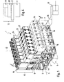
- valve battery has a longitudinal shape having fluid distributor 2, which is traversed in the direction of its longitudinal axis 5 by a fluid distributor feed channel 3 and at least one and in the present case two fluid distributor-venting channels 4a, 4b.
- a fluid distributor feed channel 3 is derived from a pressure source, not shown, which is under an operating pressure fluidic pressure medium is fed, which is in particular compressed air. Consumed compressed air can be removed via the fluid distributor ventilation channels 4a, 4b.
- the feeding and removal takes place via channel openings, not shown, on one or both of two end elements 6, 7, which are indicated in phantom in FIG. 1 and which are mounted on the front side of the fluid distributor 2.
- One of the outer surfaces of the fluid distributor 4 - has expediently a rectangular cross-section with four outer surfaces - forms a component surface 8. This is divided in the longitudinal direction of the fluid distributor 2 in a plurality of placement places, on each of which an e-lektrofluidische control unit 12 can be installed. At each placement place opens a branching from the fluid distributor feed channel 3 feed connection channel 3 'and each one of one of the two fluid distributor-venting channels 4a, 4b branching vent connection channel 4' from.
- the fluid distributor 2 is also traversed in its longitudinal direction by a receiving channel 13, which receives an electrical linkage strand 14. At each placement place, the fluid distributor 2 has at least one wall opening, through which first electrical interface means 15 of the electrical linking strand 14 are accessible from the outside. At one or both of the end elements 6, 7 is a central interface, not shown, which is connected to the electrical daisy chain 14 and which allows connection to an external electronic control device. Apart from this, an electronic control device communicating with the electrical linking strand 14 can also be located on board the valve battery 1, in particular on or in one of the two end elements 6, 7.
- the fluid distributor 2 is composed of a plurality of fluid distribution modules 16, which are placed adjacent to one another in the direction of the longitudinal axis 5 while sealing. Of these, each is equipped with at least one placement space, wherein in the present case two placement locations are present per fluid distribution module 16 by way of example.
- the modular structure would also be an integral realization of the fluid distributor 2 possible.
- the electrofluidic control units 12 each include an intermediate module 17 sitting directly on the mounting surface 8 and a multi-way valve 18 seated on the intermediate module 17 on the fluid distributor 2.
- the direction of this sequence is referred to as the height linking direction 22, which is indicated by a dot-dash line in the drawing is indicated.
- the intermediate modules 17 are attached independently of the respectively associated multi-way valve 18 on the fluid manifold 2.
- the multiway valves 18 are fixed in each case releasably on the associated intermediate module 17 via suitable fastening means 23, for example fixing screws.
- suitable fastening means 23 for example fixing screws.
- the intermediate module 17 has a lower mounting surface 24 located on the mounting surface 8 and an upper mounting surface 25 opposing the multiway valve 18.
- the multiway valve 18 is provided with a bottom surface 26 is placed in advance on the upper mounting surface 25 of the intermediate module 17.
- Each multi-way valve 18 comprises a main valve 27 with a valve spool 32 which is adjustably arranged in its main valve housing 28.
- the main valve 27 preferably has an oblong shape with a right-angled orientation, preferably both to the longitudinal axis 5 of the fluid distributor 2 and to the height-linking direction 22.
- the valve spool 32 is aligned accordingly.
- two such pilot valves 33 are present, which are combined in a pilot control unit 34 placed together on one end face of the main valve 27.
- the electrically actuable pilot valves 33 are exemplarily designed as solenoid valves. However, it could also be piezo valves or microvalves or any other electrically operable valve type.
- the main valves 27 are each designed as 5/2-way valves or as a combination of two 3/2-way valves. They include a valve feed channel 35, via which the pressure medium to be distributed to a consumer 43, which is indicated only by way of example in FIG. 1, is fed into the main valve 27.
- the consumer 43 stands with two in the main valve 27 extending valve working channels 36a, 36b in connection. Via two valve venting channels 37a, 37b, the pressure medium flowing back from the consumer can be discharged again.
- the aforementioned valve channels 35, 36, 37 each communicate at one end with a slide valve 44 containing the valve slide 32 and open at the other end to the bottom surface 26 of the main valve 27.
- the multiway valve 18 In the interior of the multiway valve 18 further extends at least one pilot channel 45, which also opens at one end to the bottom surface 26 and the other communicates with the pilot unit 34.
- a control pressure medium is fed into the multi-way valve 18, which is supplied through the intermediary of the pilot valves 33 in a selective manner two Beauftschungsabêten 46 of the valve spool 32 to impose the valve spool 32, a fluidic loading force, which shifts him to the desired switching position.
- the two pilot valves 33 are supplied from a common pilot channel 45.
- each pilot valve 33 could also be assigned a separate, separate pilot channel.
- the electrical signals required for their operation including the actuation energy receive the pilot valves 33 from the electrical interlinking line 14.
- the intermediate module 17 in the stiinverkettungsges 22 passing electrical contact means 47 are present, which are contactable at one end with the first electrical interface means 15 and the other end, in the Area of the upper mounting surface 25, are electrically contacted by second electrical interface means 48 of the pilot valves 33.
- the contacting and interface means 47, 15, 48 are preferably formed as a connector means and in any case of a type that establishes and interrupts an automatic electrical connection when the solenoid valve 18 is mounted on the intermediate module 17 and removed from this.
- valve slide 32 Between the valve spool 32 and the wall of the slide holder 44, the valve slide 32 concentrically enclosing annular seals 52 are provided. Their distribution is chosen so that in the two possible switching positions the valve spool 32 of the valve feed channel 35 is connected to one of the two valve working channels 36a and 36b, while at the same time the other valve working channel 36b or 36a with the other not connected to the valve feed channel 35 other valve vent passage 37b or 37a communicates. In this way, pressure medium can be output to the connected consumer 43 in the two switching positions via the respective one valve working channel, while at the same time pressure medium flows back through the other valve working channel.
- the intermediate module 17 has the sole purpose of being able to temporarily shut off the pressure supply of the multiway valve 18 supported by it, when the multiway valve 18 has to be temporarily removed for repair purposes and / or for replacement.
- the pressure prevailing in the fluid distributor feed channel 3 can be kept constant even if one or more of the multiway valves 18 are removed. The remaining in the valve battery 1 multi-way valves 18 can then continue to operate unrestricted.
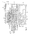
- the intermediate module 17 is penetrated by a module feed channel 53 designated channel which opens at one end - with an input-side channel mouth 54 - on the lower mounting surface 24 and the other - with an output-side channel mouth 55 - on the upper mounting surface 25.
- the channel mouths 45, 55 are placed so that the input-side channel mouth 54 is connected to the feed connection channel 3 'of the associated placement space and the output-side channel mouth 55 with the valve feed channel 35 of the multi-way valve 18.
- valve feed passage 35 is supplied through the module feed passage 53 from the fluid distribution feed passage 3 with pressure medium.
- the pilot passage 45 of the multi-way valve 18 receives the control pressure medium.
- the intermediate module 17 branches off from the module feed channel 53 from a branch channel 56, the other ends with a branch channel mouth 57 at the upper mounting surface 25, that he communicates with the present at the bottom surface 26 channel mouth 58 of the pilot channel 45 in connection.
- a plurality of branch channels 56 can also branch off from the module feed channel 53, or the channel mouths are designed such that all pilot channels 45 are fed from one and the same single branch channel 56.
- the pending in the pilot passage 45 feed pressure medium is thus about the branch channel 56 from the module feed channel 53 branched pressure medium.
- the multi-way valve 18 is thus externally supplied from the fluid manifold 2 and the intermediate module 17 with pressure. Within the multi-way valve 18, no connection between the pilot passage 45 and the valve feed passage 35 is present or required.
- the intermediate module 17 is also penetrated by two through-channels 62a, 62b in the height-linking direction 22, each of which establishes the connection between one of the fluid distributor-venting channels 4a, 4b and one of the valve-venting channels 37a, 37b.
- each one of the Valve working channels 36a, 36b connect to a running in the fluid distributor 2 fluid distributor working channel 64a, 64b, the latter open with consumer ports 65 to an outer surface of the fluid distributor 2.
- connecting means not shown in detail are provided, which allow the detachable connection of fluid lines 66, which lead to the consumer 43 to be driven, for example, to an actuatable by fluid force drive.
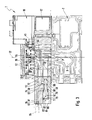
- the intermediate module 17 is equipped with a shut-off device 67 switched on in the course of the module feed channel. It contains a preferably tappet-like shut-off member 70 which is adjustably mounted in the intermediate module housing 68 and which can be switched between a shown in Figure 2, the flow through the module feed channel 53 releasing open position and a shut-off position shown in Figure 3, the module feed channel 53 ,
- the branch channel 56 branches off from the module feed channel 53 downstream of the shut-off point 69 of the shut-off device 67.
- the shut-off member 70 subdivides the module feed channel 53 at the shut-off point 69 into an upstream input side section 71 connected to the fluid distribution feed channel 3 and a downstream exit channel section 72, which is further connected to the valve feed channel 35 and 35. across the branch passage 56 - connected to the pilot channel 45.
- This position of the shut-off point 69 has the result that the multi-way valve 18 is completely separated from the pressure supply from the fluid distribution feed channel 3 in the shut-off position of the shut-off device 67. Neither the valve feed passage 35 nor the pilot passage 45 will then still supplied with pressure medium.
- the operating pressure within the fluid distribution feed channel 3 thus remains upright, which permits unrestricted operation of the further multiway valves 18 of the valve battery 1, which are likewise supplied by this fluid distribution feed channel 3.
- the shut-off device 67 could have a drive device that can be operated, for example, electrically or with other energy, with which the shut-off element 70 can be positioned as required.
- a drive device that can be operated, for example, electrically or with other energy, with which the shut-off element 70 can be positioned as required.
- the valve battery 1 since one must go to the valve battery 1 anyway for the replacement of a multi-way valve 18 on site, is usually realized in the embodiment simple variant of a purely manual, activatable solely by manually applied actuation force shut-off 67th
- the shut-off point 69 is located in the transition region between a perpendicular to theassinverkettungsraum 22 extending first channel length portion 75 of the input-side channel portion 71 and a perpendicular course adjoining thereto second channel length portion 76 which is a part of the output-side channel portion 72.
- the second channel length section 76 is adjoined in turn by a channel length section which is parallel to the first channel length section 75 and ultimately leads to the output-side channel opening 55 with a further bending.
- the shut-off member 70 is aligned in coaxial extension to the first channel length portion 45, wherein its direction indicated by a double arrow switching direction 77 coincides with the longitudinal axis 78 of the first channel length portion 75.
- the shut-off member 70 is seated in a guide recess 79 passing through the intermediate module housing 68, which connects coaxially to the first channel longitudinal section 75 and opens out via an outlet opening 80 to an end face 83 of the intermediate module housing 68 oriented at right angles to the height-linking direction 22.
- the two positions of the shut-off member 70 are defined by a guide element 79 passing through the stop element 84 which engages in a recessed on the circumference of the Absperrgliedes 70 recess 85.
- a spring means 86 By a spring means 86, the shut-off member 70 is always biased in the direction of the open position.
- the closed position can be locked by the shut-off member 70 is rotated through the outlet opening 80 therethrough with a tool, so that the stop element 84 engages in a subsequent to the recess 85 circumferential groove 87 of the shut-off member 70.
- the shut-off member 70 carries at its module feed channel 53 facing, preferably piston-like shut-off 88 two axially spaced sealing rings 89, 90. In the open position of the rear seal 89 is sealingly against the peripheral surface of the guide recess 79 and the shut-off 88 does not dive or only slightly into the module feed channel 53 ( Figure 2).
- shut-off section 88 continues to dip into the module feed channel 53, to such an extent that, with its shut-off section 88 in FIG the first channel length portion 75 is immersed and thereby sealingly abuts with its front sealing ring 90 on the wall of this first channel length portion 55. The latter causes the interruption of the fluid supply.
- the shut-off device 67 operates in the manner of a 3/2-way valve. This means that in the shut-off position according to FIG. 3 it vents the output-side channel section 72 to the atmosphere. The vent flow is shown dotted in Figure 3. In this way, a pressure reduction in the output-side channel portion 72 takes place, which simplifies the release of the solenoid valve 18. The existing fasteners are then less biased.
- a module venting channel 91 is expediently formed in the intermediate module 17, which communicates at one end with the guide recess 79 and at the other end to an outer surface 83 of the intermediate module 17 not covered by the components 2, 18 attached to the intermediate module 17 Vent opening 92 opens.
- the rear sealing ring 89 is arranged on the shut-off member 70 so that it tightly separates the junction region of the module ventilation channel 91 in the open position of the shut-off device 67 from the module feed channel 53.
- the position of the rear sealing ring 89 is selected such that it has emerged from the guide recess 79 in the shut-off position, so that a flow gap 93 is released on the circumference between the shut-off member 70 and the wall of the guide recess 79, passing a venting flow past the shut-off member 70 the module feed passage 53 is allowed into the module vent passage 91.
- the module venting channel 91 is equipped in the region of the venting opening 92 with connection means 94 which, for example, allow the attachment of a silencer 95 schematically indicated in FIG. 3 or a fluid line 96 indicated in FIG. 2, which permits a controlled removal of the exhaust air.
- shut-off member 70 comes to lie in the shut-off position with respect to the outer surface 83 deeper in the intermediate module 17 than in the open position. This results in a visual indication of the currently occupied position. In the open position, the shut-off member 70 preferably closes flush with the outer surface 83 located in the region of the outlet opening 80.
- FIG. 4 shows in a front view very schematically a further embodiment of the valve battery.
- the multi-way valve 18 is not directly, but with the interposition of at least one additional module 97 on the intermediate module 17.
- the additional module 97 may be, for example, a pressure regulator module or a throttling module. Any number of additional modules can be inserted.
- the additional modules 97 are penetrated by connecting channels, not shown, which connect the channels of the intermediate module 17 in the same assignment as in the embodiment of Figures 1 to 3 with the channels of the multi-way valve 18.
- electrical contact means are provided in the at least one additional module 97, which cause the electrical connection between the electric drive of a respective pilot valve 33 and the electrical interlinking strand 14.
- the intermediate module 17 could also be mounted on the fluid distributor 2 with the interposition of an additional module 97.
- the intermediate module 17 It is also possible to integrate in the intermediate module 17 at least one additional function which has an effect on the fluid flow, for example a throttling and / or pressure regulating function. This makes it possible to dispense with separate additional modules corresponding functionality.
Abstract
Description
- Die Erfindung betrifft eine Ventilbatterie mit mehreren in lösbarer Weise von einem Fluidverteiler getragenen und aus diesem mit Druckmedium versorgten Mehrwegeventilen, die jeweils ein Hauptventil und wenigstens ein zu dessen Ansteuerung dienendes, elektrisch betätigbares Vorsteuerventil aufweisen, wobei zwischen mindestens einem der Mehrwegeventile und dem Fluidverteiler ein Zwischenmodul angeordnet ist, das von einem einenends mit einem im Fluidverteiler laufenden Fluidverteiler-Speisekanal und andernends mit einem in dem Mehrwegeventil verlaufenden Ventil-Speisekanal verbundenen Modul-Speisekanal durchsetzt ist, wobei das wenigstens eine Vorsteuerventil aus mindestens einem im betreffenden Mehrwegeventil verlaufenden Vorsteuerkanal mit zur Ansteuerung des zugeordneten Hauptventils verwendetem Steuerdruckmedium versorgt wird und wobei das Hauptventil bei entsprechender Ansteuerung in der Lage ist, den Ventil-Speisekanal mit mindestens einem zur Ansteuerung eines Verbrauchers geeigneten Ventil-Arbeitskanal zu verbinden.
- Eine im Wesentlichen diese Merkmale aufweisende Ventilbatterie geht aus der
DE 38 22 340 C2 hervor. Sie enthält einen Fluidverteiler mit mehreren darauf unter Zwischenschaltung eines Zwischenmoduls installierten Mehrwegeventilen. Die Mehrwegeventile enthalten jeweils ein Hauptventil mit einem Ventil-Speisekanal, der über einen das Zwischenmodul durchsetzenden Modul-Speisekanal mit einem im Fluidverteiler verlaufenden Fluidverteiler-Speisekanal verbunden ist, über den sämtliche Mehrwegeventile mit Druckmedium versorgt werden. Durch elektrische Vorsteuerventile kann das Hauptventil eines jeden Mehrwegeventils in unterschiedliche Schaltstellungen verbracht werden, in denen mindestens ein Ventil-Arbeitskanal des Mehrwegeventils wahlweise mit dem Ventil-Speisekanal oder einem Entlüftungskanal verbindbar ist. Auf diese Weise kann ein an den Ventil-Arbeitskanal angeschlossener Verbraucher bestimmungsgemäß angesteuert werden. Für die Betätigung des Hauptventils scheint innerhalb des Mehrwegeventils über einen Vorsteuerkanal als Steuerdruckmedium fungierendes Druckmedium vom Ventil-Speisekanal abgezweigt zu werden, dessen Zufuhr zum Hauptventil über die elektrisch betätigbaren Vorsteuerventile individuell steuerbar ist. - Ein Nachteil der bekannten Ventilbatterie besteht darin, dass ein Austausch defekter Mehrwegeventile nur möglich ist, wenn zuvor die zentrale Druckmittelversorgung zum Fluidverteiler abgesperrt wird. Andernfalls würde die Druckluft aus dem auf Grund des entfernten Mehrwegeventils nicht mehr verschlossenen Modul-Speisekanal ungehindert austreten.
- Nach Kenntnis der Anmelderin hat man bei Ventilbatterien, deren Mehrwegeventile über Zwischenmodule an einem Fluidverteiler befestigt sind, zur Lösung der vorgenannten Problematik bereits vorgeschlagen, dem Zwischenmodul eine Absperreinrichtung zuzuordnen, die in der Lage ist, den Modul-Speisekanal abzusperren, um bei entferntem Mehrwegeventil einen Fluidaustritt aus dem Modul-Speisekanal zu verhindern. Bei dieser Ventilbatterie können jedoch, wie auch bei der eingangs diskutierten, nur solche Mehrwegeventile zum Einsatz gelangen, bei denen das Steuerdruckmedium ventilintern vom Ventil-Speisekanal abgegriffen wird.
- Der vorliegenden Erfindung liegt daher die Aufgabe zu Grunde, eine Ventilbatterie zu schaffen, bei der sich mindestens ein Mehrwegeventil auch dann ohne Beeinträchtigung der Funktion der anderen Mehrwegeventile austauschen lässt, wenn es für eine externe Einspeisung des Steuerdruckmediums ausgelegt ist.
- Zur Lösung dieser Aufgabe ist vorgesehen, dass das Zwischenmodul mit einer in den Verlauf des Modul-Speisekanals eingeschalteten, ein bedarfsgemäßes Absperren des Modul-Speisekanals ermöglichenden Absperreinrichtung ausgestattet ist, wobei von dem stromab der Absperrstelle der Absperreinrichtung liegenden ausgangsseitigen Kanalabschnitt des Modul-Speisekanals innerhalb des Zwischenmoduls mindestens ein zur Versorgung des zugeordneten Mehrwegeventils mit dem Steuerdruckmedium dienender Zweigkanal abgeht, der mit dem mindestens einen Vorsteuerkanal des mindestens einen Mehrwegeventils verbunden ist, sodass bei durch die Absperreinrichtung abgesperrtem Modul-Speisekanal gleichzeitig auch der Vorsteuerkanal des Mehrwegeventils von der Druckversorgung abgetrennt ist.
- Somit ist die Möglichkeit gegeben, dem Mehrwegeventil das zur Ansteuerung des Hauptventils verwendete Steuerdruckmedium von extern zuzuführen, und zwar aus dem Zwischenmodul heraus. Das Zwischenmodul enthält mindestens einen das Steuerdruckmedium führenden Kanal, der mit dem entsprechend verlaufenden Vorsteuerkanal des installierten Vorsteuerventils in Verbindung steht. Allerdings handelt es sich bei diesem Kanal des Zwischenmoduls nicht um einen autarken Kanal, sondern um einen innerhalb des Zwischenmoduls vom dortigen Modul-Speisekanal abzweigenden Zweigkanal. Die Abzweigstelle für diesen Zweigkanal liegt stromab einer in den Verlauf des Modul-Speisekanals eingeschalteten Absperreinrichtung, sodass das Absperren des Modul-Speisekanals gleichzeitig zur Folge hat, dass auch der Zweigkanal nicht weiter mit Druckmedium gespeist wird. Mit nur einer Absperreinrichtung des Zwischenmoduls hat man somit die Möglichkeit, gleichzeitig die Druckversorgung des Ventil-Speisekanals und des Vorsteuerkanals des Ventils abzusperren. Ist im Falle eines Defektes ein Austausch eines Mehrwegeventils notwendig, kann somit mit nur einem Handgriff und bei minimaler technischer Ausstattung des Zwischenmoduls die gesamte Druckversorgung für das Mehrwegeventil abgeschaltet werden. Das Mehrwegeventil kann dann abgenommen werden, ohne im Fluidverteiler einen Druckabfall hervorzurufen, sodass die übrigen Mehrwegeventile der Ventilbatterie weiter funktionsfähig bleiben. Ist ein Mehrwegeventil mit mehreren Vorsteuerventilen ausgestattet, können diese je nach gewählter Bauform aus einem gemeinsamen oder auch zwei separaten Zweigkanälen versorgt werden.
- Vorteilhafte Weiterbildungen der Erfindung gehen aus den Unteransprüchen hervor.
- Die erfindungsgemäße Maßnahme lässt sich sowohl realisieren, wenn das Mehrwegeventil direkt auf dem Zwischenmodul platziert ist, als auch dann, wenn zwischen dem Mehrwegeventil und dem Zwischenmodul mindestens ein weiteres Zusatzmodul installiert ist, beispielsweise ein Druckreglermodul und/oder ein Drosselungsmodul.
- Durch das Zwischenmodul hindurch findet im Normalbetrieb der Mehrwegeventile zweckmäßigerweise auch die Entlüftung des jeweils angeschlossenen Verbrauchers statt. In diesem Zusammenhang beinhaltet der Fluidverteiler dann zweckmäßigerweise mindestens einen Fluidverteiler-Entlüftungskanal, der über einen das Zwischenmodul durchsetzenden Durchgangskanal mit einem Ventil-Entlüftungskanal des zugeordneten Mehrwegeventils verbunden ist.
- Der jeweils anzusteuernde Verbraucher könnte bei entsprechender Auslegung des Mehrwegeventils direkt am Mehrwegeventil an den in diesem verlaufenden Ventil-Arbeitskanal angeschlossen werden. Als zweckmäßiger wird es jedoch erachtet, den zur Verbindung mit dem Verbraucher benötigten Verbraucheranschluss am Fluidverteiler vorzusehen und über eine den Fluidverteiler und das Zwischenmodul durchsetzende Kanalverbindung mit dem Ventil-Arbeitskanal des Mehrwegeventils zu verbinden.
- Eine vorteilhafte Weiterbildung der Erfindung sieht vor, das in dem Zwischenmodul ein mit der Atmosphäre verbundener Modul-Entlüftungskanal verläuft und die Absperreinrichtung des Zwischenmoduls so ausgebildet ist, dass sie den ausgangsseitigen Kanalabschnitt des Modul-Speisekanals und somit gleichzeitig auch den Zweigkanal mit dem Modul-Entlüftungskanal verbindet, wenn sie in die Absperrstellung umgeschaltet ist. Auf diese Weise findet ventilseitig eine Druckentlastung statt, die auch bei hohen Betriebsdrücken eine gefahrlose Demontage des Mehrwegeventils ermöglichen.
- Es ist zweckmäßig, den Modul-Entlüftungskanal mit einem derartigen Verlauf zu versehen, dass er mit einer Entlüftungsöffnung an einer Außenfläche des Zwischenmoduls ausmündet, die weder vom Fluidverteiler noch vom Mehrwegeventil oder einem optional vorhandenen Zusatzmodul abgedeckt ist. Die Entlüftungsöffnung ist somit frei zugänglich. Vorteilhaft ist dies vor allem dann, wenn der Entlüftungsöffnung Anschlussmittel zugeordnet sind, die das Anschließen eines das Geräusch der ausströmenden Luft mildernden Schalldämpfers ermöglichen oder gar den Anschluss einer wegführenden Abluftleitung, um einen Betrieb mit gefasster Abluft zu ermöglichen, beispielsweise in Verbindung mit Reinraumanwendungen.
- Die Absperreinrichtung kann über ein Absperrglied verfügen, das zwischen einer den Durchfluss durch den Modul-Speisekanal freigebenden Offenstellung und einer unter Absperrung des Modul-Speisekanals in diesen eintauchenden Absperrstellung umschaltbar ist. Bevorzugt ist die Absperreinrichtung für manuelle Betriebsweise ausgelegt, sodass keine elektrische Energie für die Betätigung erforderlich ist. In diesem Zusammenhang kann das Absperrglied so platziert werden, dass es in der Absperrstellung tiefer im Zwischenmodul zu liegen kommt, als in der Offenstellung, sodass man unmittelbar die momentan vom Absperrglied eingenommene Stellung optisch wahrnehmen kann.
- Die erfindungsgemäßen Maßnahmen lassen sich sowohl bei Ventilbatterien mit einstückigem, insbesondere plattenförmigem Fluidverteiler realisieren, als auch in Verbindung mit modular aufgebauten Fluidverteilern, die aus mehreren in einer Aufreihungsrichtung aneinander angesetzten und jeweils mindestens ein Mehrwegeventil tragenden Fluidverteilermodulen zusammengesetzt sind.
- Nachfolgend wir die Erfindung anhand der beiliegenden Zeichnungen näher erläutert. In dieser zeigen:
- Figur 1
- eine bevorzugte erste Ausführungsform der erfindungsgemäßen Ventilbatterie in perspektivischer Darstellung,
- Figur 2
- einen Querschnitt durch die Ventilbatterie im Bereich eines Mehrwegeventils gemäß Schnittlinie II-II bei in der Offenstellung befindlicher Absperreinrichtung,
- Figur 3
- die Anordnung aus Figur 2 bei in die Absperrstellung umgestalteter Absperreinrichtung, und
- Figur 4
- in schematischer Stirnansicht eine weitere Ausführungsform der Ventilbatterie, bei der das Mehrwegeventil unter Zwischenschaltung eines Zusatzmoduls auf dem unmittelbar am Fluidverteiler fixierten Zwischenmodul montiert ist.
- Die in Figuren 1 bis 3 abgebildete, insgesamt mit Bezugsziffer 1 versehene Ventilbatterie verfügt über einen Längsgestalt aufweisenden Fluidverteiler 2, der in Richtung seiner Längsachse 5 von einem Fluidverteiler-Speisekanal 3 sowie von mindestens einem und vorliegend zwei Fluidverteiler-Entlüftungskanälen 4a, 4b durchzogen ist. In den Fluidverteiler-Speisekanal 3 wird von einer nicht näher dargestellten Druckquelle stammendes, unter einem Betriebsdruck stehendes fluidisches Druckmedium eingespeist, bei dem es sich insbesondere um Druckluft handelt. Über die Fluidverteiler-Entlüftungskanäle 4a, 4b kann verbrauchte Druckluft abgeführt werden. Die Einspeisung und Abfuhr geschieht über nicht näher dargestellte Kanalöffnungen an einem oder beiden von zwei Abschlusselementen 6, 7, die in Figur 1 lediglich strichpunktiert angedeutet sind und die stirnseitig an den Fluidverteiler 2 angebaut sind.
- Eine der Außenflächen des Fluidverteilers 4 - letzterer hat zweckmäßigerweise einen rechteckigen Querschnitt mit vier Außenflächen - bildet eine Bestückungsfläche 8. Diese ist in der Längsrichtung des Fluidverteilers 2 in eine Vielzahl von Bestückungsplätzen unterteilt, an denen jeweils eine e-lektrofluidische Steuereinheit 12 installierbar ist. An jedem Bestückungsplatz mündet ein vom Fluidverteiler-Speisekanal 3 abzweigender Speise-Verbindungskanal 3' sowie je ein von einem der beiden Fluidverteiler-Entlüftungskanäle 4a, 4b abzweigender Entlüftungs-Verbindungskanal 4' aus.
- Der Fluidverteiler 2 ist in seiner Längsrichtung außerdem noch von einem Aufnahmekanal 13 durchzogen, der einen elektrischen Verkettungsstrang 14 aufnimmt. An jedem Bestückungsplatz verfügt der Fluidverteiler 2 über mindestens eine Wanddurchbrechung, durch die hindurch erste elektrische Schnittstellenmittel 15 des elektrischen Verkettungsstranges 14 von außen her zugänglich sind. An einem oder beiden der Abschlusselemente 6, 7 befindet sich eine nicht näher dargestellte zentrale Schnittstelle, die mit dem elektrischen Verkettungsstrang 14 verbunden ist und die eine Verbindung mit einer externen elektronischen Steuereinrichtung ermöglicht. Abgesehen davon kann sich eine mit dem elektrischen Verkettungsstrang 14 kommunizierende elektronische Steuereinrichtung auch an Bord der Ventilbatterie 1 befinden, insbesondere an oder in einem der beiden Abschlusselemente 6, 7.
- Beim Ausführungsbeispiel setzt sich der Fluidverteiler 2 aus einer Mehrzahl von in Richtung der Längsachse 5 unter Abdichtung aneinandergesetzten Fluidverteilermodulen 16 zusammen. Von diesen ist jedes mit mindestens einem Bestückungsplatz ausgestattet, wobei vorliegend pro Fluidverteilermodul 16 exemplarisch zwei Bestückungsplätze vorhanden sind. Anstelle des modularen Aufbaues wäre allerdings auch eine einstückige Verwirklichung des Fluidverteilers 2 möglich.
- Die elektrofluidischen Steuereinheiten 12 beinhalten jeweils ein direkt auf der Bestückungsfläche 8 sitzendes Zwischenmodul 17 und ein auf der dem Fluidverteiler 2 entgegengesetzten Seite auf dem Zwischenmodul 17 sitzendes Mehrwegeventil 18. Die Richtung dieser Aufeinanderfolge sei als Höhenverkettungsrichtung 22 bezeichnet, die in der Zeichnung durch eine strichpunktierte Linie angedeutet ist.
- Mittels nicht näher dargestellter Schrauben oder anderer Befestigungsmittel sind die Zwischenmodule 17 unabhängig vom jeweils zugeordneten Mehrwegeventil 18 am Fluidverteiler 2 befestigt. Die Mehrwegeventile 18 sind über geeignete Befestigungsmittel 23, beispielsweise Befestigungsschrauben, jeweils lösbar am zugeordneten Zwischenmodul 17 fixiert. Man kann also die einzelnen Mehrwegeventile 18 unabhängig voneinander aus der Ventilbatterie 1 entnehmen, wobei das jeweils zugeordnete Zwischenmodul 17 am Fluidverteiler 2 verbleibt.
- Insgesamt kann man somit sagen, dass die verschiedenen Mehrwegeventile 18 jeweils unter Zwischenschaltung eines Zwischenmoduls 17 in lösbarer Weise vom Fluidverteiler 2 getragen werden.
- Ohne mit den gewählten Begriffen eine Festlegung auf eine bestimmte räumliche Orientierung verbinden zu wollen, verfügt das Zwischenmodul 17 über eine auf der Bestückungsfläche 8 liegende untere Montagefläche 24 und eine dieser entgegengesetzte, das Mehrwegeventil 18 tragende obere Montagefläche 25. Das Mehrwegeventil 18 ist mit einer Bodenfläche 26 voraus auf der oberen Montagefläche 25 des Zwischenmoduls 17 platziert.
- Jedes Mehrwegeventil 18 umfasst ein Hauptventil 27 mit einem in seinem Hauptventilgehäuse 28 verstellbar angeordneten Ventilschieber 32. Das Hauptventil 27 hat bevorzugt längliche Gestalt mit bevorzugt sowohl zur Längsachse 5 des Fluidverteilers 2 als auch zur Höhenverkettungsrichtung 22 rechtwinkeliger Ausrichtung. Der Ventilschieber 32 ist entsprechend ausgerichtet. An prinzipiell beliebiger Stelle des Hauptventils 27, bevorzugt jedoch an mindestens einer Stirnseite desselben, ist mindestens ein elektrisch betätigbares Vorsteuerventil 33 angeordnet, das der Ansteuerung des Hauptventils 27 bzw. dessen Ventilschiebers 32 dient. Beim Ausführungsbeispiel sind zwei solcher Vorsteuerventile 33 vorhanden, die in einer gemeinsam an einer Stirnseite des Hauptventils 27 platzierten Vorsteuereinheit 34 zusammengefasst sind.
- Die elektrisch betätigbaren Vorsteuerventile 33 sind exemplarisch als Magnetventile ausgebildet. Es könnte sich allerdings auch um Piezoventile oder Mikroventile oder jede beliebige andere elektrisch betätigbare Ventilart handeln.
- Beim Ausführungsbeispiel sind die Hauptventile 27 jeweils als 5/2-Wegeventile oder als Kombination zweier 3/2-Wegeventile ausgeführt. Sie beinhalten einen Ventil-Speisekanal 35, über den das an einen lediglich in Figur 1 exemplarisch angedeuteten Verbraucher 43 zu verteilende Druckmedium in das Hauptventil 27 eingespeist wird. Der Verbraucher 43 steht dabei mit zwei im Hauptventil 27 verlaufenden Ventil-Arbeitskanälen 36a, 36b in Verbindung. Über zwei Ventil-Entlüftungskanäle 37a, 37b kann das vom Verbraucher zurückströmende Druckmedium wieder abgeführt werden. Die vorgenannten Ventilkanäle 35, 36, 37 kommunizieren jeweils einenends mit einer den Ventilschieber 32 enthaltenden Schieberaufnahme 44 und münden andernends zur Bodenfläche 26 des Hauptventils 27 aus.
- Im Innern des Mehrwegeventils 18 verläuft des weiteren mindestens ein Vorsteuerkanal 45, der einenends ebenfalls zu der Bodenfläche 26 ausmündet und andernends mit der Vorsteuereinheit 34 kommuniziert. Über ihn wird ein Steuerdruckmedium in das Mehrwegeventil 18 eingespeist, das unter Vermittlung der Vorsteuerventile 33 in ausgewählter Weise zwei Beaufschlagungsabschnitten 46 des Ventilschiebers 32 zuführbar ist, um dem Ventilschieber 32 eine fluidische Beaufschlagungskraft aufzuerlegen, die ihn in die gewünschte Schaltstellung verlagert. Beim Ausführungsbeispiel werden die beiden Vorsteuerventile 33 aus einem gemeinsamen Vorsteuerkanal 45 versorgt. Allerdings könnte jedem Vorsteuerventil 33 auch ein gesonderter, eigener Vorsteuerkanal zugeordnet sein.
- Die für ihren Betrieb erforderlichen elektrischen Signale einschließlich der Betätigungsenergie erhalten die Vorsteuerventile 33 von dem elektrischen Verkettungsstrang 14. Hierzu sind das Zwischenmodul 17 in der Höhenverkettungsrichtung 22 durchsetzende elektrische Kontaktierungsmittel 47 vorhanden, die einenends mit den ersten elektrischen Schnittstellenmitteln 15 kontaktierbar sind und die andernends, im Bereich der oberen Montagefläche 25, von zweiten elektrischen Schnittstellenmitteln 48 der Vorsteuerventile 33 elektrisch kontaktiert werden. Die Kontaktierungs- und Schnittstellenmittel 47, 15, 48 sind bevorzugt als Steckverbindungsmittel ausgebildet und jedenfalls von einem Typ, der eine selbsttätige elektrische Verbindung herstellt und unterbricht, wenn das Magnetventil 18 auf dem Zwischenmodul 17 montiert bzw. von diesem abgenommen wird.
- Zwischen dem Ventilschieber 32 und der Wandung der Schieberaufnahme 44 sind den Ventilschieber 32 konzentrisch umschließende ringförmige Dichtungen 52 vorgesehen. Ihre Verteilung ist so gewählt, dass in den beiden möglichen Schaltstellungen des Ventilschiebers 32 der Ventil-Speisekanal 35 mit jeweils einem der beiden Ventil-Arbeitskanäle 36a bzw. 36b verbunden ist, während gleichzeitig der jeweils andere Ventil-Arbeitskanal 36b bzw. 36a mit dem nicht mit dem Ventil-Speisekanal 35 verbundenen anderen Ventil-Entlüftungskanal 37b bzw. 37a kommuniziert. Auf diese Weise kann in den beiden Schaltstellungen über den jeweils einen Ventil-Arbeitskanal Druckmedium zum angeschlossenen Verbraucher 43 ausgegeben werden, während gleichzeitig über den anderen Ventil-Arbeitskanal Druckmedium zurückströmt.
- Das Zwischenmodul 17 hat beim Ausführungsbeispiel den alleinigen Zweck, die Druckversorgung des von ihm getragenen Mehrwegeventils 18 vorübergehend absperren zu können, wenn das Mehrwegeventil 18 zu Reparaturzwecken und/wegen eines Austausches zeitweilig entfernt werden muss. Dadurch kann der im Fluidverteiler-Speisekanal 3 herrschende Druck auch dann konstant gehalten werden, wenn eines oder mehrere der Mehrwegeventile 18 entfernt sind. Die in der Ventilbatterie 1 verbliebenen Mehrwegeventile 18 können dann weiterhin uneingeschränkt betrieben werden.
- Das Zwischenmodul 17 ist von einem als Modul-Speisekanal 53 bezeichneten Kanal durchsetzt, der einenends - mit einer eingangsseitigen Kanalmündung 54 - an der unteren Montagefläche 24 und andernends - mit einer ausgangsseitigen Kanalmündung 55 - an der oberen Montagefläche 25 ausmündet. Die Kanalmündungen 45, 55 sind dabei so platziert, dass die eingangsseitige Kanalmündung 54 mit dem Speise-Verbindungskanal 3' des zugeordneten Bestückungsplatzes und die ausgangsseitige Kanalmündung 55 mit dem Ventil-Speisekanal 35 des Mehrwegeventils 18 verbunden ist.
- Somit wird der Ventil-Speisekanal 35 durch den Modul-Speisekanal 53 hindurch aus dem Fluidverteiler-Speisekanal 3 mit Druckmedium versorgt.
- In ähnlicher Weise erhält der Vorsteuerkanal 45 des Mehrwegeventils 18 das Steuerdruckmedium. Innerhalb des Zwischenmoduls 17 zweigt vom Modul-Speisekanal 53 ein Zweigkanal 56 ab, der andernends mit einer Zweigkanalmündung 57 so an der oberen Montagefläche 25 ausmündet, dass er mit der an der Bodenfläche 26 vorhandenen Kanalmündung 58 des Vorsteuerkanals 45 in Verbindung steht. Enthält das Mehrwegeventil 18 mehrere Vorsteuerkanäle 45, können entsprechend auch mehrere Zweigkanäle 56 vom Modul-Speisekanal 53 abzweigen oder die Kanalmündungen werden so ausgebildet, dass sämtliche Vorsteuerkanäle 45 aus ein und demselben einzigen Zweigkanal 56 gespeist werden.
- Bei dem im Vorsteuerkanal 45 anstehenden Speisedruckmedium handelt es sich folglich um über den Zweigkanal 56 aus dem Modul-Speisekanal 53 abgezweigtes Druckmedium. Das Mehrwegeventil 18 wird somit von extern her, aus dem Fluidverteiler 2 bzw. dem Zwischenmodul 17 mit Druck versorgt. Innerhalb des Mehrwegeventils 18 ist keine Verbindung zwischen dem Vorsteuerkanal 45 und dem Ventil-Speisekanal 35 vorhanden bzw. erforderlich.
- Das Zwischenmodul 17 ist außerdem noch von zwei Durchgangskanälen 62a, 62b in der Höhenverkettungsrichtung 22 durchsetzt, die jeweils die Verbindung zwischen einem der Fluidverteiler-Entlüftungskanäle 4a, 4b und einem der Ventil-Entlüftungskanäle 37a, 37b herstellen.
- Schließlich ist das Zwischenmodul 17 noch von zwei weiteren Durchgangskanälen 63a, 63b durchsetzt, die jeweils einen der Ventil-Arbeitskanäle 36a, 36b mit einem im Fluidverteiler 2 verlaufenden Fluidverteiler-Arbeitskanal 64a, 64b verbinden, wobei letztere mit Verbraucheranschlüssen 65 zu einer Außenfläche des Fluidverteilers 2 ausmünden. An den Verbraucheranschlüssen 65 sind nicht näher dargestellte Anschlussmittel vorgesehen, die das lösbare Anschließen von Fluidleitungen 66 ermöglichen, die zu dem anzusteuernden Verbraucher 43 führen, beispielsweise zu einem durch Fluidkraft betätigbaren Antrieb.
- Zum Absperren der Druckversorgung des Mehrwegeventils 18 ist das Zwischenmodul 17 mit einer in den Verlauf des Modul-Speisekanals eingeschalteten Absperreinrichtung 67 ausgestattet. Sie enthält ein bevorzugt stößelartiges Absperrglied 70, das im Zwischenmodulgehäuse 68 verstellbar gelagert ist und das zwischen einer aus Figur 2 ersichtlichen, den Durchfluss durch den Modul-Speisekanal 53 freigebenden Offenstellung und einer in Figur 3 gezeigten, den Modul-Speisekanal 53 absperrenden Absperrstellung umschaltbar ist.
- Wesentlich ist dabei, dass der Zweigkanal 56 stromab der Absperrstelle 69 der Absperreinrichtung 67 vom Modul-Speisekanal 53 abzweigt. In der Absperrstellung unterteilt das Absperrglied 70 den Modul-Speisekanal 53 an der Absperrstelle 69 in einen stromauf liegenden, mit dem Fluidverteiler-Speisekanal 3 weiterhin verbundenen eingangsseitigen Kanalabschnitt 71 und einen stromab liegenden ausgangsseitigen Kanalabschnitt 72, der weiterhin mit dem Ventil-Speisekanal 35 und - über den Zweigkanal 56 hinweg - mit dem Vorsteuerkanal 45 verbunden ist. Diese Lage der Absperrstelle 69 hat zur Folge, dass das Mehrwegeventil 18 in der Absperrstellung der Absperreinrichtung 67 komplett von der Druckversorgung aus dem Fluidverteiler-Speisekanal 3 abgetrennt ist. Weder der Ventil-Speisekanal 35 noch der Vorsteuerkanal 45 werden dann noch mit Druckmedium versorgt. Man kann somit das Mehrwegeventil 18 vom Zwischenmodul 17 abnehmen, ohne dass dadurch Druckmedium durch den Modul-Speisekanal 53 hindurch zur Atmosphäre abströmt. Der Betriebsdruck innerhalb des Fluidverteiler-Speisekanals 3 bleibt mithin aufrecht, was einen uneingeschränkten Betrieb der ebenfalls von diesem Fluidverteiler-Speisekanal 3 versorgten weiteren Mehrwegeventile 18 der Ventilbatterie 1 ermöglicht.
- Die Absperreinrichtung 67 könnte eine beispielsweise elektrisch oder mit sonstiger Energie betreibbare Antriebseinrichtung aufweisen, mit der sich das Absperrglied 70 bedarfsgemäß positionieren lässt. Da man sich jedoch für den Austausch eines Mehrwegeventils 18 sowieso vor Ort zur Ventilbatterie 1 begeben muss, genügt in der Regel die auch beim Ausführungsbeispiel realisierte einfache Variante einer rein manuell, allein durch manuell aufgebrachte Betätigungskraft aktivierbaren Absperreinrichtung 67.
- Eine besonders zweckmäßige Gestaltung ist möglich, wenn der Modul-Speisekanal 53 das Zwischenmodul 17 mit einem im Wesentlichen U-förmigen Kanalverlauf durchsetzt. Die Absperrstelle 69 liegt im Übergangsbereich zwischen einem zur Höhenverkettungsrichtung 22 rechtwinkelig verlaufenden ersten Kanal-Längenabschnitt 75 des eingangsseitigen Kanalabschnittes 71 und einem sich mit rechtwinkeligem Verlauf daran anschließenden zweiten Kanal-Längenabschnitt 76, der ein Bestandteil des ausgangsseitigen Kanalabschnittes 72 ist. An den zweiten Kanal-Längenabschnitt 76 schließt sich wiederum ein zum ersten Kanal-Längenabschnitt 75 paralleler Kanal-Längenabschnitt an, der unter nochmaliger Abwinkelung letztlich zur ausgangsseitigen Kanalmündung 55 führt.
- Das Absperrglied 70 ist in koaxialer Verlängerung zu dem ersten Kanal-Längenabschnitt 45 ausgerichtet, wobei seine durch einen Doppelpfeil angedeutete Umschaltrichtung 77 mit der Längsachse 78 des ersten Kanal-Längenabschnittes 75 zusammenfällt.
- Das Absperrglied 70 sitzt in einer das Zwischenmodulgehäuse 68 durchsetzenden Führungsausnehmung 79, die sich koaxial an den ersten Kanal-Längenabschnitt 75 anschließt und über eine Austrittsöffnung 80 zu einer rechtwinkelig zur Höhenverkettungsrichtung 22 orientierten Stirnfläche 83 des Zwischenmodulgehäuses 68 ausmündet. Die beiden Stellungen des Absperrgliedes 70 sind durch ein die Führungsausnehmung 79 durchquerendes Anschlagelement 84 vorgegeben, das in eine am Umfang des Absperrgliedes 70 ausgenommene Vertiefung 85 eingreift. Durch eine Federeinrichtung 86 ist das Absperrglied 70 ständig in Richtung der Offenstellung vorgespannt. Die Schließstellung ist verriegelbar, indem das Absperrglied 70 durch die Austrittsöffnung 80 hindurch mit einem Werkzeug verdreht wird, sodass das Anschlagelement 84 in eine sich an die Vertiefung 85 anschließende Umfangsnut 87 des Absperrgliedes 70 eingreift.
- Das Absperrglied 70 trägt an seinem dem Modul-Speisekanal 53 zugewandten, bevorzugt kolbenartigen Absperrabschnitt 88 zwei axial beabstandete Dichtringe 89, 90. In der Offenstellung liegt der hintere Dichtring 89 unter Abdichtung an der Umfangsfläche der Führungsausnehmung 79 an und der Absperrabschnitt 88 taucht nicht oder nur geringfügig in den Modul-Speisekanal 53 ein (Figur 2).
- In der aus Figur 3 ersichtlichen Absperrstellung taucht der Absperrabschnitt 88 weiter in den Modul-Speisekanal 53 ein, und zwar soweit, dass er mit seinem Absperrabschnitt 88 in den ersten Kanal-Längenabschnitt 75 eintaucht und dabei mit seinem vorderen Dichtring 90 an der Wandung dieses ersten Kanal-Längenabschnittes 55 dichtend zur Anlage gelangt. Letzteres bewirkt die Unterbrechung der Fluidversorgung.
- Zweckmäßigerweise arbeitet die Absperreinrichtung 67 nach Art eines 3/2-Wegeventils. Dies bedeutet, dass sie in der Absperrstellung gemäß Figur 3 den ausgangsseitigen Kanalabschnitt 72 zur Atmosphäre entlüftet. Die Entlüftungsströmung ist in Figur 3 gepunktet eingezeichnet. Auf diese Weise findet ein Druckabbau im ausgangsseitigen Kanalabschnitt 72 statt, was das Lösen des Magnetventils 18 vereinfacht. Die vorhandenen Befestigungsmittel stehen dann weniger stark unter Vorspannung.
- Um die Entlüftungsfunktion zu realisieren, ist in dem Zwischenmodul 17 zweckmäßigerweise ein Modul-Entlüftungskanal 91 ausgebildet, der einenends mit der Führungsausnehmung 79 kommuniziert und andernends zu einer von den an das Zwischenmodul 17 angebauten Komponenten 2, 18 nicht abgedeckten Außenfläche 83 des Zwischenmoduls 17 mit einer Entlüftungsöffnung 92 ausmündet. Der hintere Dichtungsring 89 ist so am Absperrglied 70 angeordnet, dass er den Einmündungsbereich des Modul-Entlüftungskanals 91 in der Offenstellung der Absperreinrichtung 67 vom Modul-Speisekanal 53 dicht abtrennt. Andererseits ist die Position des hinteren Dichtungsringes 89 aber so gewählt, dass er in der Absperrstellung aus der Führungsausnehmung 79 herausgetreten ist, sodass umfangsseitig zwischen dem Absperrglied 70 und der Wandung der Führungsausnehmung 79 ein Strömungsspalt 93 freigegeben ist, der am Absperrglied 70 vorbei eine Entlüftungsströmung aus dem Modul-Speisekanal 53 in den Modul-Entlüftungskanal 91 gestattet.
- Zweckmäßigerweise ist der Modul-Entlüftungskanal 91 im Bereich der Entlüftungsöffnung 92 mit Anschlussmitteln 94 ausgestattet, die beispielsweise das Anbringen eines in Figur 3 schematisch angedeuteten Schalldämpfers 95 oder einer in Figur 2 angedeuteten, eine gefasste Abfuhr der Abluft ermöglichenden Fluidleitung 96 gestattet.
- Aus einem Vergleich der Figuren 2 und 3 ist ersichtlich, dass das Absperrglied 70 in der Absperrstellung bezüglich der Außenfläche 83 tiefer im Zwischenmodul 17 zu liegen kommt als in der Offenstellung. Daraus resultiert eine optische Anzeige der momentan eingenommenen Stellung. Bevorzugt schließt das Absperrglied 70 in der Offenstellung im Bereich der Austrittsöffnung 80 bündig mit der dort befindlichen Außenfläche 83 ab.
- Die Figur 4 zeigt in einer Stirnansicht sehr schematisch eine weitere Ausführungsform der Ventilbatterie. Mit der bisherigen Beschreibung übereinstimmende Komponenten sind dabei mit gleichen Bezugszeichen versehen. Im Unterschied zur Bauform der Figuren 1 bis 3 sitzt hier das Mehrwegeventil 18 nicht direkt, sondern unter Zwischenschaltung mindestens eines Zusatzmoduls 97 auf dem Zwischenmodul 17. Bei dem Zusatzmodul 97 kann es sich beispielsweise um ein Druckreglermodul oder um ein Drosselungsmodul handeln. Es ist eine beliebige Anzahl von Zusatzmodulen einfügbar. Die Zusatzmodule 97 sind von nicht näher dargestellten Verbindungskanälen durchsetzt, die die Kanäle des Zwischenmoduls 17 in gleicher Zuordnung wie beim Ausführungsbeispiel der Figuren 1 bis 3 mit den Kanälen des Mehrwegeventils 18 verbinden. Auch elektrische Kontaktmittel sind in dem mindestens einen Zusatzmodul 97 vorhanden, die die elektrische Verbindung zwischen dem elektrischen Antrieb eines jeweiligen Vorsteuerventils 33 und dem elektrischen Verkettungsstrang 14 bewirken.
- Ist mindestens ein Zusatzmodul 97 vorhanden, könnte prinzipiell das Zwischenmodul 17 auch unter Zwischenschaltung eines Zusatzmoduls 97 am Fluidverteiler 2 montiert sein.
- Es besteht auch die Möglichkeit, in das Zwischenmodul 17 mindestens eine sich auf die Fluidströmung auswirkende Zusatzfunktion zu integrieren, beispielsweise eine Drosselungs-und/oder Druckregelungsfunktion. Dadurch kann auf gesonderte Zusatzmodule entsprechender Funktionalität verzichtet werden.
Claims (14)
- Ventilbatterie, mit mehreren in lösbarer Weise von einem Fluidverteiler (2) getragenen und aus diesem mit Druckmedium versorgten Mehrwegeventilen (18), die jeweils ein Hauptventil (27) und wenigstens ein zu dessen Ansteuerung dienendes, elektrisch betätigbares Vorsteuerventil (33) aufweisen, wobei zwischen mindestens einem der Mehrwegeventile (18) und dem Fluidverteiler (2) ein Zwischenmodul (17) angeordnet ist, das von einem einenends mit einem im Fluidverteiler (2) verlaufenden Fluidverteiler-Speisekanal (3) und andernends mit einem in dem Mehrwegeventil (18) verlaufenden Ventil-Speisekanal (35) verbundenen Modul-Speisekanal (53) durchsetzt ist, wobei das wenigstens eine Vorsteuerventil (33) aus mindestens einem im betreffenden Mehrwegeventil (18) verlaufenden Vorsteuerkanal (45) mit zur Ansteuerung des zugeordneten Hauptventils (27) verwendetem Steuerdruckmedium versorgt wird und wobei das Hauptventil (27) bei entsprechender Ansteuerung in der Lage ist, den Ventil-Speisekanal (35) mit mindestens einem zur Ansteuerung eines Verbrauchers (43) geeigneten Ventil-Arbeitskanal (36a, 36b) zu verbinden, dadurch gekennzeichnet, dass das Zwischenmodul (17) mit einer in den Verlauf des Modul-Speisekanals (53) eingeschalteten, ein bedarfsgemäßes Absperren des Modul-Speisekanals (53) ermöglichenden Absperreinrichtung (67) ausgestattet ist, wobei von dem stromab der Absperrstelle (69) der Absperreinrichtung (67) liegenden ausgangsseitigen Kanalabschnitt (72) des Modul-Speisekanals (53) innerhalb des Zwischenmoduls (17) mindestens ein zur Versorgung des zugeordneten Mehrwegeventils (18) mit dem Steuerdruckmedium dienender Zweigkanal (56) abgeht, der mit dem mindestens einen Vorsteuerkanal (45) des mindestens einen Mehrwegeventils (18) verbunden ist, sodass bei durch die Absperreinrichtung (67) abgesperrtem Modul-Speisekanal (35) gleichzeitig auch der Vorsteuerkanal (45) des Mehrwegeventils (18) von der Druckversorgung abgetrennt ist.
- Ventilbatterie nach Anspruch 1, dadurch gekennzeichnet, dass das Zwischenmodul (17) eine dem Mehrwegeventil (18) zugewandte Montagefläche (25) aufweist, an der sowohl der Modul-Zwischenkanal (35) als auch der Zweigkanal (56) ausmünden und an der das Mehrwegeventil (18) direkt oder unter Zwischenschaltung mindestens eines Zusatzmoduls (97), beispielsweise ein Druckreglermodul und/oder ein Drosselungsmodul, montiert ist.
- Ventilbatterie nach Anspruch 1 oder 2, dadurch gekennzeichnet, dass in dem Fluidverteiler (2) mindestens ein Fluidverteiler-Entlüftungskanal (4a, 4b) verläuft, der über einen das Zwischenmodul (17) durchsetzenden Durchgangskanal (62a, 62b) mit einem Ventil-Entlüftungskanal (37a, 37b) des zugeordneten Mehrwegeventils (18) verbunden ist.
- Ventilbatterie nach einem der Ansprüche 1 bis 3, dadurch gekennzeichnet, dass der mindestens eine Ventil-Arbeitskanal (36a, 36b) durch das Zwischenmodul (17) hindurch mit einem Verbraucheranschluss (65) am Fluidverteiler (2) verbunden ist.
- Ventilbatterie nach einem der Ansprüche 1 bis 4, dadurch gekennzeichnet, dass in dem Zwischenmodul (17) ein Modul-Entlüftungskanal (91) verläuft und die Absperreinrichtung (67) so ausgebildet ist, dass sie in der den Modul-Speisekanal absperrenden Absperrstellung den ausgangsseitigen Kanalabschnitt (72) des Modul-Speisekanals (53) mit dem bis dahin abgetrennten Modul-Entlüftungskanal (91) verbindet.
- Ventilbatterie nach Anspruch 5, dadurch gekennzeichnet, dass der Modul-Entlüftungskanal (91) an einer von den an das Zwischenmodul angebrachten Komponenten (2, 18, 97) nicht abgedeckten Außenfläche (83) des Zwischenmoduls (17) mit einer Entlüftungsöffnung (92) ausmündet.
- Ventilbatterie nach Anspruch 6, dadurch gekennzeichnet, dass der Entlüftungsöffnung (92) Anschlussmittel (94) zum Anschließen eines Schalldämpfers (95) oder einer Abluftleitung (96) zugeordnet sind.
- Ventilbatterie nach einem der Ansprüche 1 bis 7, dadurch gekennzeichnet, dass die Absperreinrichtung (67) ein zweckmäßigerweise stößelartiges Absperrglied (70) aufweist, das zwischen einer den Durchfluss durch den Modul-Speisekanal (53) freigebenden Offenstellung und einer unter Absperrung des Modul-Speisekanals (53) in diesen eintauchenden Absperrstellung verstellbar ist.
- Ventilbatterie nach Anspruch 8, dadurch gekennzeichnet, dass das Absperrglied (70) durch eine Federeinrichtung (86) in die Offenstellung vorgespannt und in der Absperrstellung bei komprimierter Federeinrichtung (86) lösbar verriegelbar ist.
- Ventilbatterie nach Anspruch 8 oder 9, dadurch gekennzeichnet, dass der Fluidverteiler (2) und ein jeweiliges Mehrwegeventil (18) in einer Höhenverkettungsrichtung (22) übereinanderliegend angeordnet sind, wobei das Absperrglied (70) zum Umschalten zwischen der Offenstellung und der Absperrstellung in einer zu der Höhenverkettungsrichtung rechtwinkeligen Umschaltrichtung (77) verstellbar ist.
- Ventilbatterie nach Anspruch 10, dadurch gekennzeichnet, dass der Modul-Speisekanal (53) einen zur Höhenverkettungsrichtung (22) rechtwinkeligen ersten Kanal-Längenabschnitt (75) und einen sich in der Höhenverkettungsrichtung (22) daran anschließenden zweiten Kanal-Längenabschnitt (76) aufweist, wobei das Absperrglied (70) koaxial zu dem ersten Kanal-Längenabschnitt (75) ausgerichtet ist und seine Umschaltrichtung (77) mit der Längsrichtung des ersten Kanal-Längenabschnittes (75) zusammenfällt.
- Ventilbatterie nach einem der Ansprüche 1 bis 11, dadurch gekennzeichnet, dass die Absperreinrichtung (67) manuell betätigbar ausgeführt ist.
- Ventilbatterie nach Anspruch 12, dadurch gekennzeichnet, dass die Absperreinrichtung (67) ein manuell verstellbares Absperrglied (70) aufweist, das in der Absperrstellung tiefer im Zwischenmodul (17) zu liegen kommt als in der Offenstellung, wobei es in der Offenstellung zweckmäßigerweise zumindest im Wesentlichen bündig mit der Außenfläche (83) des Zwischenmoduls (17) verläuft.
- Ventilbatterie nach einem der Ansprüche 1 bis 13, gekennzeichnet durch einen modularen Aufbau des Fluidverteilers (2) mit mehreren aneinander angesetzten Fluidverteilermodulen (16), die jeweils mindestens ein Mehrwegeventil (18) tragen können.
Applications Claiming Priority (1)
| Application Number | Priority Date | Filing Date | Title |
|---|---|---|---|
| DE202005016766U DE202005016766U1 (de) | 2005-10-26 | 2005-10-26 | Ventilbatterie |
Publications (2)
| Publication Number | Publication Date |
|---|---|
| EP1780421A1 true EP1780421A1 (de) | 2007-05-02 |
| EP1780421B1 EP1780421B1 (de) | 2008-03-19 |
Family
ID=35669057
Family Applications (1)
| Application Number | Title | Priority Date | Filing Date |
|---|---|---|---|
| EP06007244A Active EP1780421B1 (de) | 2005-10-26 | 2006-04-06 | Ventilbatterie |
Country Status (3)
| Country | Link |
|---|---|
| EP (1) | EP1780421B1 (de) |
| AT (1) | ATE389814T1 (de) |
| DE (2) | DE202005016766U1 (de) |
Cited By (4)
| Publication number | Priority date | Publication date | Assignee | Title |
|---|---|---|---|---|
| EP2151587A1 (de) * | 2008-08-08 | 2010-02-10 | Asco Joucomatic | Druckdämpfungsvorrichtung |
| WO2010129669A1 (en) * | 2009-05-08 | 2010-11-11 | Siemens Industry, Inc. | Compressible fluid control system valve positioner isolation apparatus and method |
| DE102008027154C5 (de) * | 2007-06-15 | 2016-08-11 | Smc Corp. | Verteiler-Elektromagnetventilvorrichtung mit Stoppventil |
| CN107208666A (zh) * | 2015-02-06 | 2017-09-26 | 费斯托股份有限两合公司 | 阀电池 |
Families Citing this family (5)
| Publication number | Priority date | Publication date | Assignee | Title |
|---|---|---|---|---|
| DE102006010844A1 (de) * | 2006-03-09 | 2007-09-13 | Festo Ag & Co. | Ventilbatterie mit Sicherheitsventil |
| GB0721702D0 (en) * | 2007-11-06 | 2007-12-12 | Hydrogienic Global Technology | Hydrogienic globaltechnology limited |
| DE102010022624B4 (de) | 2010-06-04 | 2013-06-27 | Festo Ag & Co. Kg | Ventilanordnung |
| DE102013016652B4 (de) * | 2013-10-08 | 2022-01-27 | Festo Se & Co. Kg | Ventilbatterie mit Sicherheitsventil |
| JP6684480B2 (ja) * | 2017-05-17 | 2020-04-22 | Smc株式会社 | シリンダ駆動用マニホールド装置及びシリンダ駆動装置 |
Citations (5)
| Publication number | Priority date | Publication date | Assignee | Title |
|---|---|---|---|---|
| FR2511786A1 (fr) * | 1981-08-21 | 1983-02-25 | Climax France Sa | Module regleur d'echappement pour un distributeur d'un fluide sous pression |
| EP0822361A2 (de) * | 1996-08-01 | 1998-02-04 | Smc Corporation | An ein mehrstufiges Umschaltventil angeflanschter Druckregler |
| JPH1038119A (ja) * | 1996-07-26 | 1998-02-13 | Ckd Corp | マニホールド |
| EP0840047A2 (de) * | 1996-10-29 | 1998-05-06 | Smc Corporation | Druckregelventil montierbar an einem auf einer Grundplatte angebauten Umschaltventil |
| EP1227384A2 (de) * | 2001-01-30 | 2002-07-31 | Smc Corporation | Druckreduzierventil mit einem Abstandhalterprofil |
-
2005
- 2005-10-26 DE DE202005016766U patent/DE202005016766U1/de not_active Expired - Lifetime
-
2006
- 2006-04-06 AT AT06007244T patent/ATE389814T1/de not_active IP Right Cessation
- 2006-04-06 DE DE502006000493T patent/DE502006000493D1/de active Active
- 2006-04-06 EP EP06007244A patent/EP1780421B1/de active Active
Patent Citations (5)
| Publication number | Priority date | Publication date | Assignee | Title |
|---|---|---|---|---|
| FR2511786A1 (fr) * | 1981-08-21 | 1983-02-25 | Climax France Sa | Module regleur d'echappement pour un distributeur d'un fluide sous pression |
| JPH1038119A (ja) * | 1996-07-26 | 1998-02-13 | Ckd Corp | マニホールド |
| EP0822361A2 (de) * | 1996-08-01 | 1998-02-04 | Smc Corporation | An ein mehrstufiges Umschaltventil angeflanschter Druckregler |
| EP0840047A2 (de) * | 1996-10-29 | 1998-05-06 | Smc Corporation | Druckregelventil montierbar an einem auf einer Grundplatte angebauten Umschaltventil |
| EP1227384A2 (de) * | 2001-01-30 | 2002-07-31 | Smc Corporation | Druckreduzierventil mit einem Abstandhalterprofil |
Cited By (5)
| Publication number | Priority date | Publication date | Assignee | Title |
|---|---|---|---|---|
| DE102008027154C5 (de) * | 2007-06-15 | 2016-08-11 | Smc Corp. | Verteiler-Elektromagnetventilvorrichtung mit Stoppventil |
| EP2151587A1 (de) * | 2008-08-08 | 2010-02-10 | Asco Joucomatic | Druckdämpfungsvorrichtung |
| FR2934880A1 (fr) * | 2008-08-08 | 2010-02-12 | Asco Joucomatic Sa | Dispositif isolateur de pression. |
| WO2010129669A1 (en) * | 2009-05-08 | 2010-11-11 | Siemens Industry, Inc. | Compressible fluid control system valve positioner isolation apparatus and method |
| CN107208666A (zh) * | 2015-02-06 | 2017-09-26 | 费斯托股份有限两合公司 | 阀电池 |
Also Published As
| Publication number | Publication date |
|---|---|
| DE202005016766U1 (de) | 2006-01-12 |
| ATE389814T1 (de) | 2008-04-15 |
| EP1780421B1 (de) | 2008-03-19 |
| DE502006000493D1 (de) | 2008-04-30 |
Similar Documents
| Publication | Publication Date | Title |
|---|---|---|
| EP1780421B1 (de) | Ventilbatterie | |
| EP0002187B1 (de) | Steuerventilanordnung für zahnärztliche Geräte | |
| DE60301746T2 (de) | Pneumatikventilgruppe mit einfacher Installierung und einfacher Wartung | |
| EP2024648B1 (de) | Ventilanordnung | |
| DE60016696T2 (de) | Fluidische Wegeventilvorrichtung einer Magnetventilanordnung | |
| EP0968372B1 (de) | Ventilanordnung | |
| DE69822963T2 (de) | Verbindungseinrichtung für ein Wegeventil | |
| DE102015115593A1 (de) | Modulares Ventilsystem | |
| DE112017006181B4 (de) | Elektropneumatisches Steuergerät und damit ausgestattete Prozesssteuervorrichtung | |
| DE3427589A1 (de) | Ventiltraeger | |
| DE3810278A1 (de) | Vorgesteuerte kuehlmittelregelventile | |
| DE102018200680A1 (de) | Drucküberwachungsvorrichtung und damit ausgestattete Ventilanordnung | |
| EP3296602B1 (de) | Fluidverteilervorrichtung | |
| DE102007040929B3 (de) | Ventilanordnung mit Maßnahmen zur Drucküberwachung | |
| EP0187222A1 (de) | Ventilsteuereinrichtung für ein zahnärztliches Gerät | |
| EP1991791B1 (de) | Ventilbatterie mit sicherheitsventil | |
| EP2110563B1 (de) | Ventilanordnung mit Zentralabsperreinrichtung | |
| DE10153545B4 (de) | Fluidkraft-Verriegelungssystem und Verfahren zum Verriegeln von Fluidkraftsignalen | |
| DE10213397B4 (de) | Ventilanordnung | |
| DE2241902B2 (de) | Versorgungseinrichtung für zahnärztliche Handstucke | |
| EP2674652A1 (de) | Ventilanordnung mit Quetschventilen | |
| EP0878658B1 (de) | Progressiv-Verteilvorrichtung für Schmieranlagen | |
| DE10115913B4 (de) | Ventilanordnung | |
| DE10347590B3 (de) | Verteilermodul für Ventilbatterien | |
| EP1251283B1 (de) | Baukasten zur Herstellung eines fluidtechnischen Steuergerätes |
Legal Events
| Date | Code | Title | Description |
|---|---|---|---|
| PUAI | Public reference made under article 153(3) epc to a published international application that has entered the european phase |
Free format text: ORIGINAL CODE: 0009012 |
|
| AK | Designated contracting states |
Kind code of ref document: A1 Designated state(s): AT BE BG CH CY CZ DE DK EE ES FI FR GB GR HU IE IS IT LI LT LU LV MC NL PL PT RO SE SI SK TR |
|
| AX | Request for extension of the european patent |
Extension state: AL BA HR MK YU |
|
| 17P | Request for examination filed |
Effective date: 20070420 |
|
| GRAP | Despatch of communication of intention to grant a patent |
Free format text: ORIGINAL CODE: EPIDOSNIGR1 |
|
| GRAS | Grant fee paid |
Free format text: ORIGINAL CODE: EPIDOSNIGR3 |
|
| AKX | Designation fees paid |
Designated state(s): AT BE BG CH CY CZ DE DK EE ES FI FR GB GR HU IE IS IT LI LT LU LV MC NL PL PT RO SE SI SK TR |
|
| GRAA | (expected) grant |
Free format text: ORIGINAL CODE: 0009210 |
|
| AK | Designated contracting states |
Kind code of ref document: B1 Designated state(s): AT BE BG CH CY CZ DE DK EE ES FI FR GB GR HU IE IS IT LI LT LU LV MC NL PL PT RO SE SI SK TR |
|
| REG | Reference to a national code |
Ref country code: GB Ref legal event code: FG4D Free format text: NOT ENGLISH |
|
| REG | Reference to a national code |
Ref country code: CH Ref legal event code: EP |
|
| REF | Corresponds to: |
Ref document number: 502006000493 Country of ref document: DE Date of ref document: 20080430 Kind code of ref document: P |
|
| REG | Reference to a national code |
Ref country code: IE Ref legal event code: FG4D Free format text: LANGUAGE OF EP DOCUMENT: GERMAN |
|
| GBT | Gb: translation of ep patent filed (gb section 77(6)(a)/1977) |
Effective date: 20080425 |
|
| PG25 | Lapsed in a contracting state [announced via postgrant information from national office to epo] |
Ref country code: LT Free format text: LAPSE BECAUSE OF FAILURE TO SUBMIT A TRANSLATION OF THE DESCRIPTION OR TO PAY THE FEE WITHIN THE PRESCRIBED TIME-LIMIT Effective date: 20080319 Ref country code: FI Free format text: LAPSE BECAUSE OF FAILURE TO SUBMIT A TRANSLATION OF THE DESCRIPTION OR TO PAY THE FEE WITHIN THE PRESCRIBED TIME-LIMIT Effective date: 20080319 |
|
| NLV1 | Nl: lapsed or annulled due to failure to fulfill the requirements of art. 29p and 29m of the patents act | ||
| PG25 | Lapsed in a contracting state [announced via postgrant information from national office to epo] |
Ref country code: SI Free format text: LAPSE BECAUSE OF FAILURE TO SUBMIT A TRANSLATION OF THE DESCRIPTION OR TO PAY THE FEE WITHIN THE PRESCRIBED TIME-LIMIT Effective date: 20080319 Ref country code: LV Free format text: LAPSE BECAUSE OF FAILURE TO SUBMIT A TRANSLATION OF THE DESCRIPTION OR TO PAY THE FEE WITHIN THE PRESCRIBED TIME-LIMIT Effective date: 20080319 Ref country code: PL Free format text: LAPSE BECAUSE OF FAILURE TO SUBMIT A TRANSLATION OF THE DESCRIPTION OR TO PAY THE FEE WITHIN THE PRESCRIBED TIME-LIMIT Effective date: 20080319 |
|
| REG | Reference to a national code |
Ref country code: IE Ref legal event code: FD4D |
|
| BERE | Be: lapsed |
Owner name: FESTO A.G. & CO. Effective date: 20080430 |
|
| PG25 | Lapsed in a contracting state [announced via postgrant information from national office to epo] |
Ref country code: SK Free format text: LAPSE BECAUSE OF FAILURE TO SUBMIT A TRANSLATION OF THE DESCRIPTION OR TO PAY THE FEE WITHIN THE PRESCRIBED TIME-LIMIT Effective date: 20080319 Ref country code: PT Free format text: LAPSE BECAUSE OF FAILURE TO SUBMIT A TRANSLATION OF THE DESCRIPTION OR TO PAY THE FEE WITHIN THE PRESCRIBED TIME-LIMIT Effective date: 20080827 Ref country code: ES Free format text: LAPSE BECAUSE OF FAILURE TO SUBMIT A TRANSLATION OF THE DESCRIPTION OR TO PAY THE FEE WITHIN THE PRESCRIBED TIME-LIMIT Effective date: 20080630 Ref country code: CZ Free format text: LAPSE BECAUSE OF FAILURE TO SUBMIT A TRANSLATION OF THE DESCRIPTION OR TO PAY THE FEE WITHIN THE PRESCRIBED TIME-LIMIT Effective date: 20080319 Ref country code: SE Free format text: LAPSE BECAUSE OF FAILURE TO SUBMIT A TRANSLATION OF THE DESCRIPTION OR TO PAY THE FEE WITHIN THE PRESCRIBED TIME-LIMIT Effective date: 20080619 |
|
| PG25 | Lapsed in a contracting state [announced via postgrant information from national office to epo] |
Ref country code: RO Free format text: LAPSE BECAUSE OF FAILURE TO SUBMIT A TRANSLATION OF THE DESCRIPTION OR TO PAY THE FEE WITHIN THE PRESCRIBED TIME-LIMIT Effective date: 20080319 Ref country code: NL Free format text: LAPSE BECAUSE OF FAILURE TO SUBMIT A TRANSLATION OF THE DESCRIPTION OR TO PAY THE FEE WITHIN THE PRESCRIBED TIME-LIMIT Effective date: 20080319 Ref country code: MC Free format text: LAPSE BECAUSE OF NON-PAYMENT OF DUE FEES Effective date: 20080430 |
|
| PG25 | Lapsed in a contracting state [announced via postgrant information from national office to epo] |
Ref country code: IS Free format text: LAPSE BECAUSE OF FAILURE TO SUBMIT A TRANSLATION OF THE DESCRIPTION OR TO PAY THE FEE WITHIN THE PRESCRIBED TIME-LIMIT Effective date: 20080719 |
|
| PLBE | No opposition filed within time limit |
Free format text: ORIGINAL CODE: 0009261 |
|
| STAA | Information on the status of an ep patent application or granted ep patent |
Free format text: STATUS: NO OPPOSITION FILED WITHIN TIME LIMIT |
|
| PG25 | Lapsed in a contracting state [announced via postgrant information from national office to epo] |
Ref country code: IE Free format text: LAPSE BECAUSE OF FAILURE TO SUBMIT A TRANSLATION OF THE DESCRIPTION OR TO PAY THE FEE WITHIN THE PRESCRIBED TIME-LIMIT Effective date: 20080319 Ref country code: EE Free format text: LAPSE BECAUSE OF FAILURE TO SUBMIT A TRANSLATION OF THE DESCRIPTION OR TO PAY THE FEE WITHIN THE PRESCRIBED TIME-LIMIT Effective date: 20080319 Ref country code: DK Free format text: LAPSE BECAUSE OF FAILURE TO SUBMIT A TRANSLATION OF THE DESCRIPTION OR TO PAY THE FEE WITHIN THE PRESCRIBED TIME-LIMIT Effective date: 20080319 |
|
| 26N | No opposition filed |
Effective date: 20081222 |
|
| PG25 | Lapsed in a contracting state [announced via postgrant information from national office to epo] |
Ref country code: BE Free format text: LAPSE BECAUSE OF NON-PAYMENT OF DUE FEES Effective date: 20080430 |
|
| PG25 | Lapsed in a contracting state [announced via postgrant information from national office to epo] |
Ref country code: BG Free format text: LAPSE BECAUSE OF FAILURE TO SUBMIT A TRANSLATION OF THE DESCRIPTION OR TO PAY THE FEE WITHIN THE PRESCRIBED TIME-LIMIT Effective date: 20080619 |
|
| PG25 | Lapsed in a contracting state [announced via postgrant information from national office to epo] |
Ref country code: AT Free format text: LAPSE BECAUSE OF NON-PAYMENT OF DUE FEES Effective date: 20080406 |
|
| PG25 | Lapsed in a contracting state [announced via postgrant information from national office to epo] |
Ref country code: CY Free format text: LAPSE BECAUSE OF FAILURE TO SUBMIT A TRANSLATION OF THE DESCRIPTION OR TO PAY THE FEE WITHIN THE PRESCRIBED TIME-LIMIT Effective date: 20080319 |
|
| PG25 | Lapsed in a contracting state [announced via postgrant information from national office to epo] |
Ref country code: HU Free format text: LAPSE BECAUSE OF FAILURE TO SUBMIT A TRANSLATION OF THE DESCRIPTION OR TO PAY THE FEE WITHIN THE PRESCRIBED TIME-LIMIT Effective date: 20080920 Ref country code: LU Free format text: LAPSE BECAUSE OF NON-PAYMENT OF DUE FEES Effective date: 20080406 |
|
| PG25 | Lapsed in a contracting state [announced via postgrant information from national office to epo] |
Ref country code: TR Free format text: LAPSE BECAUSE OF FAILURE TO SUBMIT A TRANSLATION OF THE DESCRIPTION OR TO PAY THE FEE WITHIN THE PRESCRIBED TIME-LIMIT Effective date: 20080319 |
|
| PG25 | Lapsed in a contracting state [announced via postgrant information from national office to epo] |
Ref country code: GR Free format text: LAPSE BECAUSE OF FAILURE TO SUBMIT A TRANSLATION OF THE DESCRIPTION OR TO PAY THE FEE WITHIN THE PRESCRIBED TIME-LIMIT Effective date: 20080620 |
|
| REG | Reference to a national code |
Ref country code: CH Ref legal event code: PL |
|
| PG25 | Lapsed in a contracting state [announced via postgrant information from national office to epo] |
Ref country code: LI Free format text: LAPSE BECAUSE OF NON-PAYMENT OF DUE FEES Effective date: 20100430 Ref country code: CH Free format text: LAPSE BECAUSE OF NON-PAYMENT OF DUE FEES Effective date: 20100430 |
|
| PGFP | Annual fee paid to national office [announced via postgrant information from national office to epo] |
Ref country code: GB Payment date: 20150325 Year of fee payment: 10 |
|
| REG | Reference to a national code |
Ref country code: FR Ref legal event code: PLFP Year of fee payment: 11 |
|
| GBPC | Gb: european patent ceased through non-payment of renewal fee |
Effective date: 20160406 |
|
| PG25 | Lapsed in a contracting state [announced via postgrant information from national office to epo] |
Ref country code: GB Free format text: LAPSE BECAUSE OF NON-PAYMENT OF DUE FEES Effective date: 20160406 |
|
| REG | Reference to a national code |
Ref country code: FR Ref legal event code: PLFP Year of fee payment: 12 |
|
| PGFP | Annual fee paid to national office [announced via postgrant information from national office to epo] |
Ref country code: FR Payment date: 20170424 Year of fee payment: 12 |
|
| PGFP | Annual fee paid to national office [announced via postgrant information from national office to epo] |
Ref country code: IT Payment date: 20170420 Year of fee payment: 12 |
|
| PG25 | Lapsed in a contracting state [announced via postgrant information from national office to epo] |
Ref country code: IT Free format text: LAPSE BECAUSE OF NON-PAYMENT OF DUE FEES Effective date: 20180406 Ref country code: FR Free format text: LAPSE BECAUSE OF NON-PAYMENT OF DUE FEES Effective date: 20180430 |
|
| REG | Reference to a national code |
Ref country code: DE Ref legal event code: R082 Ref document number: 502006000493 Country of ref document: DE Representative=s name: PATENTANWAELTE MAGENBAUER & KOLLEGEN PARTNERSC, DE Ref country code: DE Ref legal event code: R081 Ref document number: 502006000493 Country of ref document: DE Owner name: FESTO SE & CO. KG, DE Free format text: FORMER OWNER: FESTO AG & CO. KG, 73734 ESSLINGEN, DE Ref country code: DE Ref legal event code: R081 Ref document number: 502006000493 Country of ref document: DE Owner name: FESTO AG & CO. KG, DE Free format text: FORMER OWNER: FESTO AG & CO. KG, 73734 ESSLINGEN, DE |
|
| PGFP | Annual fee paid to national office [announced via postgrant information from national office to epo] |
Ref country code: DE Payment date: 20220622 Year of fee payment: 18 |
|
| P01 | Opt-out of the competence of the unified patent court (upc) registered |
Effective date: 20230623 |