EP1780137A1 - Manual device to facilitate the emptying of tubes storing pastry products - Google Patents
Manual device to facilitate the emptying of tubes storing pastry products Download PDFInfo
- Publication number
- EP1780137A1 EP1780137A1 EP06380260A EP06380260A EP1780137A1 EP 1780137 A1 EP1780137 A1 EP 1780137A1 EP 06380260 A EP06380260 A EP 06380260A EP 06380260 A EP06380260 A EP 06380260A EP 1780137 A1 EP1780137 A1 EP 1780137A1
- Authority
- EP
- European Patent Office
- Prior art keywords
- arms
- tube
- pair
- arm
- emptying
- Prior art date
- Legal status (The legal status is an assumption and is not a legal conclusion. Google has not performed a legal analysis and makes no representation as to the accuracy of the status listed.)
- Granted
Links
Images
Classifications
-
- B—PERFORMING OPERATIONS; TRANSPORTING
- B65—CONVEYING; PACKING; STORING; HANDLING THIN OR FILAMENTARY MATERIAL
- B65D—CONTAINERS FOR STORAGE OR TRANSPORT OF ARTICLES OR MATERIALS, e.g. BAGS, BARRELS, BOTTLES, BOXES, CANS, CARTONS, CRATES, DRUMS, JARS, TANKS, HOPPERS, FORWARDING CONTAINERS; ACCESSORIES, CLOSURES, OR FITTINGS THEREFOR; PACKAGING ELEMENTS; PACKAGES
- B65D35/00—Pliable tubular containers adapted to be permanently or temporarily deformed to expel contents, e.g. collapsible tubes for toothpaste or other plastic or semi-liquid material; Holders therefor
- B65D35/24—Pliable tubular containers adapted to be permanently or temporarily deformed to expel contents, e.g. collapsible tubes for toothpaste or other plastic or semi-liquid material; Holders therefor with auxiliary devices
- B65D35/28—Pliable tubular containers adapted to be permanently or temporarily deformed to expel contents, e.g. collapsible tubes for toothpaste or other plastic or semi-liquid material; Holders therefor with auxiliary devices for expelling contents
Definitions
- the invention relates to a manual device designed to facilitate the emptying of tubes storing pasty products, such as toothpaste, cosmetics, adhesive, paint pastes, or sealants and/or silicones.
- the device is characterised in that it is comprised of a pair of flat, substantially elongated arms, articulately joined together at one of their ends by way of a means of coupling comprised of a pair of tabs, folded orthogonally and provided with respective orifices, axially aligned, at the end of the first arm, and a pair of extensions, folded orthogonally and provided with respective protuberances, at the end of the second arm; the tabs and the extensions being adapted so that the arms are joined by the lodging of the protuberances of one arm in the orifices of the other, determining a space between said coupled arms through which an empty, flattened portion of the tube may be inserted and slid, and in that said arms are provided with inflexions whose fold lines are parallel with and close to the axis whereon the respective arms swing, and they are designed to pinch the tube together and to prevent the passage towards the closed end of the tube of the product stored in the same when the arms are brought together in order to exert pressure on the portion of the
- the aforementioned manual device is especially designed, as is disclosed in these characteristics, to be manufactured in only two component parts.
- the edges of the free ends of the arms are each provided with cut-outs whose profile is complementary to that of the nozzles of conventional tubes.
- the fold lines of the inflexions determine an appendix on each of the arms of the device, said appendices being divergent from each other when said arms are parallel and whereon the means of coupling is arranged.
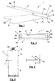
- the manual device 1 depicted in Figure 1 is designed to facilitate the emptying of tubes storing toothpaste products.
- Said device is composed of a pair of elongated, flat arms 3 and 4, which are articulately joined together at one of their ends by a means of coupling 5.
- Said manual device 1 is therefore composed of only two component parts which, by way of a stamping and folding process, adopt the final shape of arms 3 and 4 depicted in Figures 1, 2, 3 and 4. In this way, the process of producing these is simplified and manufacturing costs are reduced, avoiding operations such as welding or riveting, in comparison with other known devices.
- the means of coupling 5 is comprised of a pair of tabs 5a, folded orthogonally and provided with respective orifices 5b, axially aligned, at the end of the first arm 3, and a pair of extensions 5c, folded orthogonally and provided with respective protuberances 5d, at the end of the second arm 4, the measurements being such that arms 3 and 4 are articulately joined by means of housing the protuberances 5d of arm 4 in the orifices 5b of arm 3.
- the profile of the tabs 5a and of the extensions 5c is rounded, so that said profiles do not interfere with the inner wall of the opposing arms. Specifically, in the example of Figure 3, said characteristic prevents the extensions 5c from interfering with the rotation of the arms of the device due to their ends abutting against arm 3.
- arms 3 and 4 are both equipped with inflexions 7a and 7b, whose fold lines 7c and 7d are parallel with, and close to the axis whereon the respective arms 3 and 4 swing, as portrayed in Figure 1.
- Said fold lines 7c and 7d are designed to pinch tube 2 together and to prevent the passage towards the closed end of tube 2 of the product stored in the same when arms 3 and 4 are brought together in order to exert pressure on the portion of tube 2 placed between them and to expel, by means of this pressure, the product stored in tube 2 through the nozzle 8 of the tube 2.
- the edges of the free ends 9 of arms 3 and 4 are each provided with cut-outs 9a and 9b.
- the profile of said cut-outs 9a and 9b is complementary to that of the nozzles 8 of conventional tubes 2, thus guaranteeing the total emptying of the pasty product from the tube 2, it being possible to exert pressure by means of arms 3 and 4 on the front end of the tube 2 without interfering with the nozzle 8 of said tube 2, which will be partially surrounded by cut-outs 9a and 9b of arms 3 and 4 respectively.
- Fold lines 7c and 7d of arms 3 and 4 each determine appendices 10 at the opposite ends to their free ends, which are divergent from each other when arms 3 and 4 are parallel. These appendices 10 are designed to restrict the opening of arms 3 and 4 by abutment of appendix 10 of one arm against appendix 10 of the opposite arm.
- the device 1 remains open with its arms 3 and 4 essentially disposed perpendicularly one in relation to the other; thus, said device 1, with the tube 2 held between arms 3 and 4, may rest on the edge of a horizontal surface, such as a shelf, by resting one of its arms 3 or 4 on said surface, as portrayed in Figure 4.
- the means of coupling 5 is arranged on said appendices 10 of arms 3 and 4.
- the lateral edges 11 of the respective arms 3 and 4 are slightly curved inwards, which permits easier grasping of the device 1 in order to move it longitudinally with regard to the paste tube 2.
- the manual device 1 of the invention may be manufactured from two sheets of metallic material such as carbon steel, stainless steel or similar, subjected to a process of stamping, punching and pressing (to provide the sheet with orifices 5b and protuberances 5d) and folding (to provide the sheet with orthogonal tabs 5a and extensions 5c) which give rise to arms 3 and 4, or by means of a process of moulding by injection of a plastic or polymeric material.
- metallic material such as carbon steel, stainless steel or similar
Landscapes
- Engineering & Computer Science (AREA)
- Mechanical Engineering (AREA)
- Tubes (AREA)
- Containers And Packaging Bodies Having A Special Means To Remove Contents (AREA)
Abstract
Description
- The invention relates to a manual device designed to facilitate the emptying of tubes storing pasty products, such as toothpaste, cosmetics, adhesive, paint pastes, or sealants and/or silicones.
- Currently, the majority of pasty products, such as toothpaste, cosmetics, adhesive, paint pastes or sealants and/or silicones are stored in flexible, tubular containers. These tubular containers require manipulation to empty the same, which consists of exerting pressure with the fingers from the rear end of the tube, towards its front end, in order to push the paste stored and to cause its egress through a nozzle provided for that purpose at the said front end of the tube.
- When the user exerts pressure on the tube with the thumbs of his/her hand, the pressure transmitted to the paste is irregular; as a result of this, part of the pasty product accumulates inside the tube at its rear part, in spite of the fact that the product stored is expelled through the nozzle of the tube. As a result, it is difficult to extract all the paste content from the tube without repeating the emptying manoeuvre several times.
- On the other hand, nowadays the majority of these tubes are manufactured from polymeric materials, one of whose properties is their elasticity; therefore, although the tube may be easily deformable in order to extract the paste through the nozzle of the tube, said tube recovers its original position due to its elastic behaviour, and whenever it is desired to extract paste, the same operation must be performed again, repeatedly and with greater intensity, in order to extract the paste once more.
- With the object of trying to resolve some of the difficulties of this manual operation and of alleviating the task of emptying, in the State of the Art there exist a number of manual devices for facilitating the emptying of pasty material from the tube storing the same. Among these devices may be found the device disclosed in patent document
DE3627701 , which discloses a pincer which consists of two plastic pressure keys configured symmetrically one in relation to the other, and a metal bar or pin to which both keys are rotably joined. This device requires a laborious manufacturing process as it is composed of three component parts, and besides, it does not guarantee the extraction of the totality of the pasty material stored in the tube. - Another example of these manual devices is disclosed in patent document
ES1057275 - In order to provide a solution to the problems outlined above, a manual device designed to facilitate the emptying of tubes storing pasty products is disclosed.
- In essence, the device is characterised in that it is comprised of a pair of flat, substantially elongated arms, articulately joined together at one of their ends by way of a means of coupling comprised of a pair of tabs, folded orthogonally and provided with respective orifices, axially aligned, at the end of the first arm, and a pair of extensions, folded orthogonally and provided with respective protuberances, at the end of the second arm; the tabs and the extensions being adapted so that the arms are joined by the lodging of the protuberances of one arm in the orifices of the other, determining a space between said coupled arms through which an empty, flattened portion of the tube may be inserted and slid, and in that said arms are provided with inflexions whose fold lines are parallel with and close to the axis whereon the respective arms swing, and they are designed to pinch the tube together and to prevent the passage towards the closed end of the tube of the product stored in the same when the arms are brought together in order to exert pressure on the portion of the tube placed between them and to expel, by means of this pressure, the product stored in the tube through the nozzle of the same.
- The aforementioned manual device is especially designed, as is disclosed in these characteristics, to be manufactured in only two component parts.
- In accordance with another characteristic of the invention, the edges of the free ends of the arms are each provided with cut-outs whose profile is complementary to that of the nozzles of conventional tubes.
- In accordance with another characteristic of the invention, the fold lines of the inflexions determine an appendix on each of the arms of the device, said appendices being divergent from each other when said arms are parallel and whereon the means of coupling is arranged.
- In the attached drawings, a preferred embodiment of the manual device for facilitating the emptying of tubes storing pasty substances which is the object of the invention is shown as a non-limiting example. In said drawings:
- Figure 1 is a schematic perspective depiction a manual device according to the invention;
- Figure 2 is a schematic elevational view of the device in Figure 1, in its operating position;
- Figure 3 is a schematic sectional view of the device in Figure 1, wherein details of the means of
coupling 5 between the arms which comprise said device may be seen; and - Figure 4 is a schematic view of the device in Figure 1 at rest on a shelf.
- The
manual device 1 depicted in Figure 1 is designed to facilitate the emptying of tubes storing toothpaste products. Said device is composed of a pair of elongated,flat arms coupling 5. Saidmanual device 1 is therefore composed of only two component parts which, by way of a stamping and folding process, adopt the final shape ofarms - As is depicted in greater detail in Figure 3, exaggeratedly for easier understanding, the means of
coupling 5 is comprised of a pair oftabs 5a, folded orthogonally and provided withrespective orifices 5b, axially aligned, at the end of thefirst arm 3, and a pair ofextensions 5c, folded orthogonally and provided withrespective protuberances 5d, at the end of thesecond arm 4, the measurements being such thatarms protuberances 5d ofarm 4 in theorifices 5b ofarm 3. - In order to facilitate the rotating movement between
arms tabs 5a and of theextensions 5c is rounded, so that said profiles do not interfere with the inner wall of the opposing arms. Specifically, in the example of Figure 3, said characteristic prevents theextensions 5c from interfering with the rotation of the arms of the device due to their ends abutting againstarm 3. - When both
arms tube 2 is inserted and slid, themanual device 1 being configured longitudinally with thetube 2, as depicted in Figure 2. - Furthermore,
arms inflexions fold lines respective arms fold lines tube 2 together and to prevent the passage towards the closed end oftube 2 of the product stored in the same whenarms tube 2 placed between them and to expel, by means of this pressure, the product stored intube 2 through thenozzle 8 of thetube 2. - In accordance with the depictions in Figures 1 and 2, the edges of the
free ends 9 ofarms outs outs nozzles 8 ofconventional tubes 2, thus guaranteeing the total emptying of the pasty product from thetube 2, it being possible to exert pressure by means ofarms tube 2 without interfering with thenozzle 8 ofsaid tube 2, which will be partially surrounded by cut-outs arms - Fold
lines arms appendices 10 at the opposite ends to their free ends, which are divergent from each other whenarms appendices 10 are designed to restrict the opening ofarms appendix 10 of one arm againstappendix 10 of the opposite arm. When this happens, thedevice 1 remains open with itsarms device 1, with thetube 2 held betweenarms arms coupling 5 is arranged on saidappendices 10 ofarms - As may be seen in Figure 2, the
lateral edges 11 of therespective arms device 1 in order to move it longitudinally with regard to thepaste tube 2. - It should be mentioned that the
manual device 1 of the invention may be manufactured from two sheets of metallic material such as carbon steel, stainless steel or similar, subjected to a process of stamping, punching and pressing (to provide the sheet withorifices 5b andprotuberances 5d) and folding (to provide the sheet withorthogonal tabs 5a andextensions 5c) which give rise toarms
Claims (3)
- Manual device (1) designed to facilitate the emptying of tubes (2) storing pasty products, such as toothpaste, cosmetics, adhesive, paint pastes, or sealants and/or silicones, characterized in that it comprises a pair of flat, substantially elongated arms (3 and 4), articulately joined together at one of their ends by way of a means of coupling (5) comprised of a pair of tabs (5a), folded orthogonally and provided with respective orifices (5b), axially aligned, at the end of the first arm (3), and a pair of extensions (5c), folded orthogonally and provided with respective protuberances (5d), at the end of the second arm (4); the tabs (5a) and the extensions (5c) being adapted so that the arms (3 and 4) are joined by the lodging of the protuberances (5d) of one arm in the orifices (5b) of the other, determining a space (6) between said coupled arms (3 and 4) through which an empty, flattened portion of the tube (2) may be inserted and slid, and in that said arms (3 and 4) are each provided with inflexions (7a and 7b) whose fold lines (7c and 7d) are parallel with and close to the axis whereon the respective arms (3 and 4) swing, and are designed to pinch the tube (2) together and to prevent the passage towards the closed end of the tube (2) of the product stored in the same when the arms (3 and 4) are brought together in order to exert pressure on the portion of the tube placed between them and to expel, by means of this pressure, the product stored in the tube (2) through the nozzle (8) of the same.
- Device (1) according to claim 1, characterized in that the edges of the free ends (9) of the arms are each provided with cut-outs (9a and 9b) whose profile is complementary to that of the nozzles (8) of conventional tubes (2).
- Device (1) according to either of the preceding claims, characterized in that the fold lines (7c and 7d) of the inflexions (7a and 7b) determine an appendix (10) on each of the arms (3 and 4) of the device 1, said appendices (10) being divergent from each other when said arms (3 and 4) are parallel and whereon the means of coupling (5) is arranged.
Applications Claiming Priority (1)
| Application Number | Priority Date | Filing Date | Title |
|---|---|---|---|
| ES200502624A ES2296472B1 (en) | 2005-10-28 | 2005-10-28 | MANUAL DEVICE TO FACILITATE THE EMPTYING OF PIPES THAT STORE PASTRY PRODUCTS. |
Publications (2)
| Publication Number | Publication Date |
|---|---|
| EP1780137A1 true EP1780137A1 (en) | 2007-05-02 |
| EP1780137B1 EP1780137B1 (en) | 2013-04-17 |
Family
ID=37735208
Family Applications (1)
| Application Number | Title | Priority Date | Filing Date |
|---|---|---|---|
| EP06380260.7A Not-in-force EP1780137B1 (en) | 2005-10-28 | 2006-10-06 | Manual device to facilitate the emptying of tubes storing pastry products |
Country Status (3)
| Country | Link |
|---|---|
| US (1) | US20070095858A1 (en) |
| EP (1) | EP1780137B1 (en) |
| ES (1) | ES2296472B1 (en) |
Cited By (1)
| Publication number | Priority date | Publication date | Assignee | Title |
|---|---|---|---|---|
| CN104276336A (en) * | 2014-11-07 | 2015-01-14 | 吉首大学 | Toothpaste squeezing device |
Families Citing this family (2)
| Publication number | Priority date | Publication date | Assignee | Title |
|---|---|---|---|---|
| US20120223099A1 (en) * | 2011-03-03 | 2012-09-06 | Roy Sanchez | Fold and Squeeze Condiment Packet Sauce Wrapper |
| US20230210317A1 (en) * | 2023-03-14 | 2023-07-06 | Shenzhen Karon Electric Technology Co., Ltd. | Full-automatic induction extrusion apparatus for emulsion and paste in tube packages |
Citations (6)
| Publication number | Priority date | Publication date | Assignee | Title |
|---|---|---|---|---|
| US2643029A (en) * | 1951-01-11 | 1953-06-23 | Chapman William John | Tube holder and dispenser with pivotally mounted tube-squeezing member |
| US5683013A (en) * | 1995-01-31 | 1997-11-04 | The Testor Corporation | Paint dispensing system |
| US5743434A (en) * | 1995-12-15 | 1998-04-28 | Light; Homer Edwin | Collapsible tube compressing device |
| NL1004869C1 (en) * | 1996-12-20 | 1998-06-23 | New Products & Systems B V | Holder for tubes containing pastes |
| US6234353B1 (en) | 1999-04-13 | 2001-05-22 | Homer E. Light | Dispensing tube compressor |
| ES1057275U (en) | 2004-04-21 | 2004-07-01 | Companyia Andorrana De Llevataps, S.L. | Container regulator expulsion tubes paste products. (Machine-translation by Google Translate, not legally binding) |
Family Cites Families (15)
| Publication number | Priority date | Publication date | Assignee | Title |
|---|---|---|---|---|
| US1242165A (en) * | 1916-07-12 | 1917-10-09 | John W Fitzgerald | Fire-extinguisher. |
| GB419383A (en) * | 1934-02-08 | 1934-11-12 | Harold Boyd | New or improved ejecting means for use more particularly in connection with collapsible tubular fire extinguishers |
| US2759636A (en) * | 1954-04-23 | 1956-08-21 | John C Albert | Dispensing device for paste tubes |
| US2790579A (en) * | 1955-03-02 | 1957-04-30 | Woldorf Herman | Dispensing device for collapsible tubes |
| FR1159246A (en) * | 1956-09-07 | 1958-06-25 | Apparatus for extracting the entire contents of a flexible tube | |
| FR1183770A (en) * | 1956-09-27 | 1959-07-13 | Device for expressing pasty or semi-liquid products out of collapsible tubes | |
| US3675822A (en) * | 1970-09-03 | 1972-07-11 | Gino Casali | Tube squeezer |
| US4326647A (en) * | 1980-05-22 | 1982-04-27 | Pool Dan L | Device for dispensing fluent material from a collapsible container |
| US4565303A (en) * | 1984-11-01 | 1986-01-21 | Gilbertson John E | Device for dispensing paste from a tube |
| US5105983A (en) * | 1989-10-31 | 1992-04-21 | Block Medical, Inc. | Infusion apparatus |
| US5105984A (en) * | 1990-06-27 | 1992-04-21 | Kazimir Charles E | Paste tube dispenser and method for making same |
| US5322194A (en) * | 1992-08-04 | 1994-06-21 | Roberts Allen L | Dispenser for collapsible tubes |
| FR2765559B1 (en) * | 1997-07-01 | 1999-09-03 | Oreal | DEVICE FOR THE FRACTIONAL DRAINING OF A TUBE |
| WO2003086897A1 (en) * | 2002-04-15 | 2003-10-23 | Unilever N.V. | Device for storing and squeezing sachets |
| US6669055B1 (en) * | 2002-08-21 | 2003-12-30 | Thomas J. Coleman | Holder for viscous fluid dispenser |
-
2005
- 2005-10-28 ES ES200502624A patent/ES2296472B1/en not_active Expired - Fee Related
-
2006
- 2006-10-06 EP EP06380260.7A patent/EP1780137B1/en not_active Not-in-force
- 2006-10-25 US US11/585,868 patent/US20070095858A1/en not_active Abandoned
Patent Citations (6)
| Publication number | Priority date | Publication date | Assignee | Title |
|---|---|---|---|---|
| US2643029A (en) * | 1951-01-11 | 1953-06-23 | Chapman William John | Tube holder and dispenser with pivotally mounted tube-squeezing member |
| US5683013A (en) * | 1995-01-31 | 1997-11-04 | The Testor Corporation | Paint dispensing system |
| US5743434A (en) * | 1995-12-15 | 1998-04-28 | Light; Homer Edwin | Collapsible tube compressing device |
| NL1004869C1 (en) * | 1996-12-20 | 1998-06-23 | New Products & Systems B V | Holder for tubes containing pastes |
| US6234353B1 (en) | 1999-04-13 | 2001-05-22 | Homer E. Light | Dispensing tube compressor |
| ES1057275U (en) | 2004-04-21 | 2004-07-01 | Companyia Andorrana De Llevataps, S.L. | Container regulator expulsion tubes paste products. (Machine-translation by Google Translate, not legally binding) |
Cited By (1)
| Publication number | Priority date | Publication date | Assignee | Title |
|---|---|---|---|---|
| CN104276336A (en) * | 2014-11-07 | 2015-01-14 | 吉首大学 | Toothpaste squeezing device |
Also Published As
| Publication number | Publication date |
|---|---|
| ES2296472A1 (en) | 2008-04-16 |
| ES2296472B1 (en) | 2009-03-01 |
| EP1780137B1 (en) | 2013-04-17 |
| US20070095858A1 (en) | 2007-05-03 |
Similar Documents
| Publication | Publication Date | Title |
|---|---|---|
| EP2488078B1 (en) | Wall-mounted metering dispenser | |
| EP3275556B1 (en) | Liquid dispenser | |
| EP0601244B1 (en) | Apparatus for dispensing material from collapsible tubes | |
| EP1780137B1 (en) | Manual device to facilitate the emptying of tubes storing pastry products | |
| WO2011009221A1 (en) | Metering dispenser | |
| DE29905296U1 (en) | Multi-purpose pliers | |
| US8747007B2 (en) | Decorating pen | |
| US5743434A (en) | Collapsible tube compressing device | |
| US6966457B1 (en) | Spring-loaded tube squeezing device | |
| WO2005087063A1 (en) | Hand press for food | |
| US5890625A (en) | Device for the fractional emptying of a tube | |
| US5975363A (en) | Device for aiding in expelling the contents of a collapsible tube | |
| US5195660A (en) | Clamping type caulking gun | |
| DE202008008468U1 (en) | Tool for opening closely adhering walls of plastic bags and bags | |
| AU776642B2 (en) | Apparatus and package for the metered dispensing of a viscous material | |
| US20070131710A1 (en) | Squeeze tube volume reducer | |
| US1728147A (en) | Tooth-paste ejector | |
| JP3220454U (en) | Tube squeezer | |
| US5199611A (en) | Apparatus for squeezing material from collapsible tubes | |
| KR101551717B1 (en) | the tube wringer | |
| JP3112151U (en) | Fluid squeezing tool in the storage bag | |
| KR20040008995A (en) | baking machine | |
| DE60302523T2 (en) | Segmenter for citrus fruits | |
| DE202012103004U1 (en) | tongs | |
| AT503920B1 (en) | Device e.g. for squeezing tube, has first long section and parallel long part for tube opening and second long section with outer side has slit and opening |
Legal Events
| Date | Code | Title | Description |
|---|---|---|---|
| PUAI | Public reference made under article 153(3) epc to a published international application that has entered the european phase |
Free format text: ORIGINAL CODE: 0009012 |
|
| AK | Designated contracting states |
Kind code of ref document: A1 Designated state(s): AT BE BG CH CY CZ DE DK EE ES FI FR GB GR HU IE IS IT LI LT LU LV MC NL PL PT RO SE SI SK TR |
|
| AX | Request for extension of the european patent |
Extension state: AL BA HR MK YU |
|
| 17P | Request for examination filed |
Effective date: 20070925 |
|
| AKX | Designation fees paid |
Designated state(s): AT BE BG CH CY CZ DE DK EE ES FI FR GB GR HU IE IS IT LI LT LU LV MC NL PL PT RO SE SI SK TR |
|
| 17Q | First examination report despatched |
Effective date: 20111215 |
|
| GRAP | Despatch of communication of intention to grant a patent |
Free format text: ORIGINAL CODE: EPIDOSNIGR1 |
|
| GRAS | Grant fee paid |
Free format text: ORIGINAL CODE: EPIDOSNIGR3 |
|
| GRAA | (expected) grant |
Free format text: ORIGINAL CODE: 0009210 |
|
| AK | Designated contracting states |
Kind code of ref document: B1 Designated state(s): AT BE BG CH CY CZ DE DK EE ES FI FR GB GR HU IE IS IT LI LT LU LV MC NL PL PT RO SE SI SK TR |
|
| REG | Reference to a national code |
Ref country code: GB Ref legal event code: FG4D |
|
| REG | Reference to a national code |
Ref country code: CH Ref legal event code: EP |
|
| REG | Reference to a national code |
Ref country code: IE Ref legal event code: FG4D |
|
| REG | Reference to a national code |
Ref country code: AT Ref legal event code: REF Ref document number: 607137 Country of ref document: AT Kind code of ref document: T Effective date: 20130515 |
|
| REG | Reference to a national code |
Ref country code: DE Ref legal event code: R096 Ref document number: 602006035698 Country of ref document: DE Effective date: 20130606 |
|
| REG | Reference to a national code |
Ref country code: AT Ref legal event code: MK05 Ref document number: 607137 Country of ref document: AT Kind code of ref document: T Effective date: 20130417 |
|
| REG | Reference to a national code |
Ref country code: LT Ref legal event code: MG4D |
|
| REG | Reference to a national code |
Ref country code: NL Ref legal event code: VDEP Effective date: 20130417 |
|
| PG25 | Lapsed in a contracting state [announced via postgrant information from national office to epo] |
Ref country code: IS Free format text: LAPSE BECAUSE OF FAILURE TO SUBMIT A TRANSLATION OF THE DESCRIPTION OR TO PAY THE FEE WITHIN THE PRESCRIBED TIME-LIMIT Effective date: 20130817 Ref country code: AT Free format text: LAPSE BECAUSE OF FAILURE TO SUBMIT A TRANSLATION OF THE DESCRIPTION OR TO PAY THE FEE WITHIN THE PRESCRIBED TIME-LIMIT Effective date: 20130417 Ref country code: SE Free format text: LAPSE BECAUSE OF FAILURE TO SUBMIT A TRANSLATION OF THE DESCRIPTION OR TO PAY THE FEE WITHIN THE PRESCRIBED TIME-LIMIT Effective date: 20130417 Ref country code: PT Free format text: LAPSE BECAUSE OF FAILURE TO SUBMIT A TRANSLATION OF THE DESCRIPTION OR TO PAY THE FEE WITHIN THE PRESCRIBED TIME-LIMIT Effective date: 20130819 Ref country code: SI Free format text: LAPSE BECAUSE OF FAILURE TO SUBMIT A TRANSLATION OF THE DESCRIPTION OR TO PAY THE FEE WITHIN THE PRESCRIBED TIME-LIMIT Effective date: 20130417 Ref country code: LT Free format text: LAPSE BECAUSE OF FAILURE TO SUBMIT A TRANSLATION OF THE DESCRIPTION OR TO PAY THE FEE WITHIN THE PRESCRIBED TIME-LIMIT Effective date: 20130417 Ref country code: FI Free format text: LAPSE BECAUSE OF FAILURE TO SUBMIT A TRANSLATION OF THE DESCRIPTION OR TO PAY THE FEE WITHIN THE PRESCRIBED TIME-LIMIT Effective date: 20130417 Ref country code: GR Free format text: LAPSE BECAUSE OF FAILURE TO SUBMIT A TRANSLATION OF THE DESCRIPTION OR TO PAY THE FEE WITHIN THE PRESCRIBED TIME-LIMIT Effective date: 20130718 Ref country code: BE Free format text: LAPSE BECAUSE OF FAILURE TO SUBMIT A TRANSLATION OF THE DESCRIPTION OR TO PAY THE FEE WITHIN THE PRESCRIBED TIME-LIMIT Effective date: 20130417 Ref country code: ES Free format text: LAPSE BECAUSE OF FAILURE TO SUBMIT A TRANSLATION OF THE DESCRIPTION OR TO PAY THE FEE WITHIN THE PRESCRIBED TIME-LIMIT Effective date: 20130728 |
|
| PG25 | Lapsed in a contracting state [announced via postgrant information from national office to epo] |
Ref country code: PL Free format text: LAPSE BECAUSE OF FAILURE TO SUBMIT A TRANSLATION OF THE DESCRIPTION OR TO PAY THE FEE WITHIN THE PRESCRIBED TIME-LIMIT Effective date: 20130417 Ref country code: CY Free format text: LAPSE BECAUSE OF FAILURE TO SUBMIT A TRANSLATION OF THE DESCRIPTION OR TO PAY THE FEE WITHIN THE PRESCRIBED TIME-LIMIT Effective date: 20130417 Ref country code: LV Free format text: LAPSE BECAUSE OF FAILURE TO SUBMIT A TRANSLATION OF THE DESCRIPTION OR TO PAY THE FEE WITHIN THE PRESCRIBED TIME-LIMIT Effective date: 20130417 Ref country code: BG Free format text: LAPSE BECAUSE OF FAILURE TO SUBMIT A TRANSLATION OF THE DESCRIPTION OR TO PAY THE FEE WITHIN THE PRESCRIBED TIME-LIMIT Effective date: 20130717 |
|
| PG25 | Lapsed in a contracting state [announced via postgrant information from national office to epo] |
Ref country code: EE Free format text: LAPSE BECAUSE OF FAILURE TO SUBMIT A TRANSLATION OF THE DESCRIPTION OR TO PAY THE FEE WITHIN THE PRESCRIBED TIME-LIMIT Effective date: 20130417 Ref country code: SK Free format text: LAPSE BECAUSE OF FAILURE TO SUBMIT A TRANSLATION OF THE DESCRIPTION OR TO PAY THE FEE WITHIN THE PRESCRIBED TIME-LIMIT Effective date: 20130417 Ref country code: DK Free format text: LAPSE BECAUSE OF FAILURE TO SUBMIT A TRANSLATION OF THE DESCRIPTION OR TO PAY THE FEE WITHIN THE PRESCRIBED TIME-LIMIT Effective date: 20130417 Ref country code: CZ Free format text: LAPSE BECAUSE OF FAILURE TO SUBMIT A TRANSLATION OF THE DESCRIPTION OR TO PAY THE FEE WITHIN THE PRESCRIBED TIME-LIMIT Effective date: 20130417 |
|
| PLBE | No opposition filed within time limit |
Free format text: ORIGINAL CODE: 0009261 |
|
| STAA | Information on the status of an ep patent application or granted ep patent |
Free format text: STATUS: NO OPPOSITION FILED WITHIN TIME LIMIT |
|
| PG25 | Lapsed in a contracting state [announced via postgrant information from national office to epo] |
Ref country code: NL Free format text: LAPSE BECAUSE OF FAILURE TO SUBMIT A TRANSLATION OF THE DESCRIPTION OR TO PAY THE FEE WITHIN THE PRESCRIBED TIME-LIMIT Effective date: 20130417 Ref country code: RO Free format text: LAPSE BECAUSE OF FAILURE TO SUBMIT A TRANSLATION OF THE DESCRIPTION OR TO PAY THE FEE WITHIN THE PRESCRIBED TIME-LIMIT Effective date: 20130417 Ref country code: IT Free format text: LAPSE BECAUSE OF FAILURE TO SUBMIT A TRANSLATION OF THE DESCRIPTION OR TO PAY THE FEE WITHIN THE PRESCRIBED TIME-LIMIT Effective date: 20130417 |
|
| 26N | No opposition filed |
Effective date: 20140120 |
|
| REG | Reference to a national code |
Ref country code: DE Ref legal event code: R097 Ref document number: 602006035698 Country of ref document: DE Effective date: 20140120 |
|
| PG25 | Lapsed in a contracting state [announced via postgrant information from national office to epo] |
Ref country code: MC Free format text: LAPSE BECAUSE OF FAILURE TO SUBMIT A TRANSLATION OF THE DESCRIPTION OR TO PAY THE FEE WITHIN THE PRESCRIBED TIME-LIMIT Effective date: 20130417 |
|
| REG | Reference to a national code |
Ref country code: CH Ref legal event code: PL |
|
| REG | Reference to a national code |
Ref country code: IE Ref legal event code: MM4A |
|
| PG25 | Lapsed in a contracting state [announced via postgrant information from national office to epo] |
Ref country code: CH Free format text: LAPSE BECAUSE OF NON-PAYMENT OF DUE FEES Effective date: 20131031 Ref country code: LI Free format text: LAPSE BECAUSE OF NON-PAYMENT OF DUE FEES Effective date: 20131031 |
|
| PG25 | Lapsed in a contracting state [announced via postgrant information from national office to epo] |
Ref country code: IE Free format text: LAPSE BECAUSE OF NON-PAYMENT OF DUE FEES Effective date: 20131006 |
|
| PG25 | Lapsed in a contracting state [announced via postgrant information from national office to epo] |
Ref country code: TR Free format text: LAPSE BECAUSE OF FAILURE TO SUBMIT A TRANSLATION OF THE DESCRIPTION OR TO PAY THE FEE WITHIN THE PRESCRIBED TIME-LIMIT Effective date: 20130417 |
|
| PG25 | Lapsed in a contracting state [announced via postgrant information from national office to epo] |
Ref country code: HU Free format text: LAPSE BECAUSE OF FAILURE TO SUBMIT A TRANSLATION OF THE DESCRIPTION OR TO PAY THE FEE WITHIN THE PRESCRIBED TIME-LIMIT; INVALID AB INITIO Effective date: 20061006 Ref country code: LU Free format text: LAPSE BECAUSE OF NON-PAYMENT OF DUE FEES Effective date: 20131006 |
|
| REG | Reference to a national code |
Ref country code: FR Ref legal event code: PLFP Year of fee payment: 10 |
|
| REG | Reference to a national code |
Ref country code: FR Ref legal event code: PLFP Year of fee payment: 11 |
|
| PGFP | Annual fee paid to national office [announced via postgrant information from national office to epo] |
Ref country code: DE Payment date: 20160928 Year of fee payment: 11 |
|
| REG | Reference to a national code |
Ref country code: FR Ref legal event code: PLFP Year of fee payment: 12 |
|
| REG | Reference to a national code |
Ref country code: DE Ref legal event code: R119 Ref document number: 602006035698 Country of ref document: DE |
|
| PG25 | Lapsed in a contracting state [announced via postgrant information from national office to epo] |
Ref country code: DE Free format text: LAPSE BECAUSE OF NON-PAYMENT OF DUE FEES Effective date: 20180501 |
|
| REG | Reference to a national code |
Ref country code: FR Ref legal event code: PLFP Year of fee payment: 13 |
|
| PGFP | Annual fee paid to national office [announced via postgrant information from national office to epo] |
Ref country code: FR Payment date: 20191026 Year of fee payment: 14 |
|
| PG25 | Lapsed in a contracting state [announced via postgrant information from national office to epo] |
Ref country code: FR Free format text: LAPSE BECAUSE OF NON-PAYMENT OF DUE FEES Effective date: 20201031 |
|
| PGFP | Annual fee paid to national office [announced via postgrant information from national office to epo] |
Ref country code: GB Payment date: 20231023 Year of fee payment: 18 |
|
| GBPC | Gb: european patent ceased through non-payment of renewal fee |
Effective date: 20241006 |
|
| PG25 | Lapsed in a contracting state [announced via postgrant information from national office to epo] |
Ref country code: GB Free format text: LAPSE BECAUSE OF NON-PAYMENT OF DUE FEES Effective date: 20241006 |