EP1779923A1 - A mixer with a stirrer having tapered blades - Google Patents
A mixer with a stirrer having tapered blades Download PDFInfo
- Publication number
- EP1779923A1 EP1779923A1 EP07001668A EP07001668A EP1779923A1 EP 1779923 A1 EP1779923 A1 EP 1779923A1 EP 07001668 A EP07001668 A EP 07001668A EP 07001668 A EP07001668 A EP 07001668A EP 1779923 A1 EP1779923 A1 EP 1779923A1
- Authority
- EP
- European Patent Office
- Prior art keywords
- paddle blade
- flat paddle
- vessel
- agitating
- flat
- Prior art date
- Legal status (The legal status is an assumption and is not a legal conclusion. Google has not performed a legal analysis and makes no representation as to the accuracy of the status listed.)
- Granted
Links
Images


Classifications
-
- B—PERFORMING OPERATIONS; TRANSPORTING
- B01—PHYSICAL OR CHEMICAL PROCESSES OR APPARATUS IN GENERAL
- B01F—MIXING, e.g. DISSOLVING, EMULSIFYING OR DISPERSING
- B01F25/00—Flow mixers; Mixers for falling materials, e.g. solid particles
- B01F25/50—Circulation mixers, e.g. wherein at least part of the mixture is discharged from and reintroduced into a receptacle
- B01F25/52—Circulation mixers, e.g. wherein at least part of the mixture is discharged from and reintroduced into a receptacle with a rotary stirrer in the recirculation tube
-
- B—PERFORMING OPERATIONS; TRANSPORTING
- B01—PHYSICAL OR CHEMICAL PROCESSES OR APPARATUS IN GENERAL
- B01F—MIXING, e.g. DISSOLVING, EMULSIFYING OR DISPERSING
- B01F27/00—Mixers with rotary stirring devices in fixed receptacles; Kneaders
- B01F27/05—Stirrers
- B01F27/07—Stirrers characterised by their mounting on the shaft
- B01F27/072—Stirrers characterised by their mounting on the shaft characterised by the disposition of the stirrers with respect to the rotating axis
- B01F27/0725—Stirrers characterised by their mounting on the shaft characterised by the disposition of the stirrers with respect to the rotating axis on the free end of the rotating axis
-
- B—PERFORMING OPERATIONS; TRANSPORTING
- B01—PHYSICAL OR CHEMICAL PROCESSES OR APPARATUS IN GENERAL
- B01F—MIXING, e.g. DISSOLVING, EMULSIFYING OR DISPERSING
- B01F27/00—Mixers with rotary stirring devices in fixed receptacles; Kneaders
- B01F27/80—Mixers with rotary stirring devices in fixed receptacles; Kneaders with stirrers rotating about a substantially vertical axis
- B01F27/90—Mixers with rotary stirring devices in fixed receptacles; Kneaders with stirrers rotating about a substantially vertical axis with paddles or arms
- B01F27/906—Mixers with rotary stirring devices in fixed receptacles; Kneaders with stirrers rotating about a substantially vertical axis with paddles or arms with fixed axis
-
- B—PERFORMING OPERATIONS; TRANSPORTING
- B01—PHYSICAL OR CHEMICAL PROCESSES OR APPARATUS IN GENERAL
- B01F—MIXING, e.g. DISSOLVING, EMULSIFYING OR DISPERSING
- B01F33/00—Other mixers; Mixing plants; Combinations of mixers
- B01F33/80—Mixing plants; Combinations of mixers
- B01F33/83—Mixing plants specially adapted for mixing in combination with disintegrating operations
- B01F33/831—Devices with consecutive working receptacles, e.g. with two intermeshing tools in one of the receptacles
-
- B—PERFORMING OPERATIONS; TRANSPORTING
- B01—PHYSICAL OR CHEMICAL PROCESSES OR APPARATUS IN GENERAL
- B01F—MIXING, e.g. DISSOLVING, EMULSIFYING OR DISPERSING
- B01F35/00—Accessories for mixers; Auxiliary operations or auxiliary devices; Parts or details of general application
- B01F35/10—Maintenance of mixers
- B01F35/145—Washing or cleaning mixers not provided for in other groups in this subclass; Inhibiting build-up of material on machine parts using other means
- B01F35/1452—Washing or cleaning mixers not provided for in other groups in this subclass; Inhibiting build-up of material on machine parts using other means using fluids
- B01F35/1453—Washing or cleaning mixers not provided for in other groups in this subclass; Inhibiting build-up of material on machine parts using other means using fluids by means of jets of fluid, e.g. air
-
- B—PERFORMING OPERATIONS; TRANSPORTING
- B01—PHYSICAL OR CHEMICAL PROCESSES OR APPARATUS IN GENERAL
- B01F—MIXING, e.g. DISSOLVING, EMULSIFYING OR DISPERSING
- B01F35/00—Accessories for mixers; Auxiliary operations or auxiliary devices; Parts or details of general application
- B01F35/90—Heating or cooling systems
- B01F35/92—Heating or cooling systems for heating the outside of the receptacle, e.g. heated jackets or burners
-
- B—PERFORMING OPERATIONS; TRANSPORTING
- B01—PHYSICAL OR CHEMICAL PROCESSES OR APPARATUS IN GENERAL
- B01F—MIXING, e.g. DISSOLVING, EMULSIFYING OR DISPERSING
- B01F35/00—Accessories for mixers; Auxiliary operations or auxiliary devices; Parts or details of general application
- B01F35/90—Heating or cooling systems
- B01F35/95—Heating or cooling systems using heated or cooled stirrers
-
- B—PERFORMING OPERATIONS; TRANSPORTING
- B01—PHYSICAL OR CHEMICAL PROCESSES OR APPARATUS IN GENERAL
- B01F—MIXING, e.g. DISSOLVING, EMULSIFYING OR DISPERSING
- B01F35/00—Accessories for mixers; Auxiliary operations or auxiliary devices; Parts or details of general application
- B01F35/90—Heating or cooling systems
- B01F2035/98—Cooling
-
- B—PERFORMING OPERATIONS; TRANSPORTING
- B01—PHYSICAL OR CHEMICAL PROCESSES OR APPARATUS IN GENERAL
- B01F—MIXING, e.g. DISSOLVING, EMULSIFYING OR DISPERSING
- B01F27/00—Mixers with rotary stirring devices in fixed receptacles; Kneaders
- B01F27/05—Stirrers
- B01F27/07—Stirrers characterised by their mounting on the shaft
- B01F27/072—Stirrers characterised by their mounting on the shaft characterised by the disposition of the stirrers with respect to the rotating axis
- B01F27/0721—Stirrers characterised by their mounting on the shaft characterised by the disposition of the stirrers with respect to the rotating axis parallel with respect to the rotating axis
-
- B—PERFORMING OPERATIONS; TRANSPORTING
- B01—PHYSICAL OR CHEMICAL PROCESSES OR APPARATUS IN GENERAL
- B01F—MIXING, e.g. DISSOLVING, EMULSIFYING OR DISPERSING
- B01F27/00—Mixers with rotary stirring devices in fixed receptacles; Kneaders
- B01F27/05—Stirrers
- B01F27/07—Stirrers characterised by their mounting on the shaft
- B01F27/072—Stirrers characterised by their mounting on the shaft characterised by the disposition of the stirrers with respect to the rotating axis
- B01F27/0724—Stirrers characterised by their mounting on the shaft characterised by the disposition of the stirrers with respect to the rotating axis directly mounted on the rotating axis
-
- B—PERFORMING OPERATIONS; TRANSPORTING
- B01—PHYSICAL OR CHEMICAL PROCESSES OR APPARATUS IN GENERAL
- B01F—MIXING, e.g. DISSOLVING, EMULSIFYING OR DISPERSING
- B01F27/00—Mixers with rotary stirring devices in fixed receptacles; Kneaders
- B01F27/05—Stirrers
- B01F27/11—Stirrers characterised by the configuration of the stirrers
- B01F27/112—Stirrers characterised by the configuration of the stirrers with arms, paddles, vanes or blades
- B01F27/1122—Stirrers characterised by the configuration of the stirrers with arms, paddles, vanes or blades anchor-shaped
-
- B—PERFORMING OPERATIONS; TRANSPORTING
- B01—PHYSICAL OR CHEMICAL PROCESSES OR APPARATUS IN GENERAL
- B01F—MIXING, e.g. DISSOLVING, EMULSIFYING OR DISPERSING
- B01F27/00—Mixers with rotary stirring devices in fixed receptacles; Kneaders
- B01F27/05—Stirrers
- B01F27/11—Stirrers characterised by the configuration of the stirrers
- B01F27/112—Stirrers characterised by the configuration of the stirrers with arms, paddles, vanes or blades
- B01F27/1125—Stirrers characterised by the configuration of the stirrers with arms, paddles, vanes or blades with vanes or blades extending parallel or oblique to the stirrer axis
Definitions
- pigment pastes are generally prepared by the steps of mixing pigments, resins, organic solvents, and like raw materials in an agitator to prepare a mill base, and then passing this mill base a few times through a bead mill dispersion apparatus or like continuous dispersion apparatus to disperse the pigment.
- the commonly employed pigment dispersion method comprises the steps of feeding an unprocessed pigment paste stored in a feeding vessel to a dispersion apparatus, temporarily storing the pigment paste obtained by dispersing it in the dispersion apparatus in a receiving vessel, returning the pigment paste stored in the receiving vessel to the dispersion apparatus to redisperse it after the completion of the first pigment dispersion process, and returning the pigment paste which has been subjected to the second pigment dispersion process to the feeding vessel to store it, and then repeating these processes a few times.
- the above-mentioned manufacturing process disadvantageously requires two vessels, i.e., feeding vessel and receiving vessel, and operations to switch between these vessels.
- a known technique connects an agitator and a dispersion apparatus via a circulation line to circulate pigment paste between the apparatuses, unifying the feeding vessel and receiving vessel (for example, refer to Japanese Unexamined Patent Publication N°s. 1996-266880 and 2002-306940 ).
- a known bead mill apparatus (cf. Japanese Unexamined Patent Publication N° 1996-266880 , Japanese Examined Patent Publication N° 1994-28745 and Japanese Unexamined Patent Publication N° 2002-204969 ) having a mechanism which separates pigment paste from a grinding medium by the action of centrifugal force caused by the rotation of a rotor has such advantages that it has a large throughput (flow rate); it requires only one vessel because it allows circulation dispersion; and it does not require a switching operation between a feeding vessel and a receiving vessel because it has only one vessel.
- a double-shafted mixer having a high-speed agitator and a low-speed anchor type agitating blade which removes the pooled mill base off the vessel wall was developed.
- said double-shaft mixer has the problem of high installation cost.
- a small interval between the vessel wall and anchor type agitating blade makes cleaning the mill base by injecting a cleaning solvent difficult, the mixer still has a problem in its ability to be cleaned when the mixer is applied to the production of coating compositions, which requires the frequent replacement of materials.
- the inventors of the present invention have previously improved the constitution of paddle blades and proposed an agitator which can be applied to a circulatory system with a large flow rate, can deal with a variety of fluids, changes in fluid volume, and has an excellent ability to mix and disperse fluids with different viscosities ranging from low to high and cleanability (refer to Japanese Patent No. 3189047 ).
- a cleaning device ejects a cleaning liquid from a cleaning nozzle connected to a cleaning liquid tank into the agitating vessel (for example, refer to Japanese Patent No. 3189047 ).
- This cleaning device showers the inner wall of the agitating vessel and the surface of the agitating blade with the cleaning liquid from the cleaning liquid tank via the cleaning nozzle to wash away pigment paste deposited therein.
- the cleaning liquid ejected from the cleaning liquid nozzle into the agitating vessel is immediately drawn out from the bottom of the agitating vessel, collected and recycled.
- the aforementioned known improved agitator previously proposed by the inventors of the present invention is capable of cleaning the flat paddle blade and the inner wall of an agitating vessel by circulating a cleaning liquid and has a much higher cleanability than the aforementioned known double-shaft mixer because it employs a flat paddle blade, pigment paste deposited on the outermost peripheral surface (flat surface) of the flat paddle blade and the pigment paste deposited on the bottom of the agitating vessel are sometimes a little difficult to scrape off.
- a cleaning liquid is collected in the agitating vessel, and then the flat paddle blade and the inner wall of the agitating vessel is cleaned by rotating the flat paddle blade backwards and forwards. At this time, the cleaning liquid simultaneously cleans the inside of the bead mill apparatus by circulating through the circulatory channel connecting the bead mill apparatus and the agitator.
- the inventors of the present invention have conducted extensive research, and consequently found that in the prior art, including the previously proposed improved agitator, pigment paste deposited on the flat surface around the agitating blade tends to pool during circulation dispersion since the peripheral edge of the agitating blade is a flat surface as shown in the cross section of Fig. 8, which results in lowered dispersibility. They also found that pigment paste readily adheres and deposits on the flat surface of the agitating blade and cannot be sufficiently cleaned by the cleaning liquid ejected from the cleaning nozzle.
- the inventors of the present invention have found that the flow of cleaning liquid fed through a fluid inlet provided in an upper part of the agitating vessel, discharged through a fluid outlet provided in the bottom, and circulated inside the agitator and bead mill apparatus through the circulatory channel of the bead mill apparatus sometimes pools at the bottom of the agitating vessel.
- an object of the present invention is to provide an agitator with increased cleanability of a paddle blade and an agitating vessel of the agitator.
- the agitator according to the present invention has an agitating vessel comprising a fluid inlet in an upper part thereof, a fluid outlet at the bottom, and having a cylindrical peripheral configuration; a rotating shaft extending vertically inside the agitating vessel; and a flat paddle blade mounted on said rotating shaft, the flat paddle blade having a bottom flat paddle blade portion which extends outwards from the bottom of the rotating shaft and a oblong upper flat paddle blade portion extending upward from an upper part of each side end of the bottom flat paddle blade portion, the outermost periphery of the flat paddle blade being tapered by two inclined surfaces.
- the outermost periphery of the flat paddle blade has a V-shaped peripheral configuration formed by the two inclined surfaces and each of said inclined surfaces is formed so that the internal angle ( ⁇ 1 ) between a flat surface of the flat paddle blade and the inclined surface is in the range of from 100°to 140°.
- the bottom configuration of the agitating vessel preferably is in the shape of a cone or a truncated cone tapering downwards, and the bottom configuration of the bottom flat paddle blade portion is preferably formed parallel with the bottom of the agitating vessel.
- the bottom conical surface of the agitating vessel preferably has an inclination so that the angle ( ⁇ 2 ) of the surface is 5°-30° from horizontal.
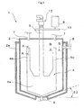
- Fig. 1 is a longitudinal sectional view showing the inner structure of the agitator
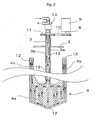
- Fig. 2 is a partial longitudinal sectional view showing the inner structure of the flat paddle blade part of Fig. 1.
- the agitator 1 has an agitating vessel 2; a rotating shaft 3 extending vertically in the inner center of the agitating vessel 2; and a flat paddle blade 4 as an agitating blade mounted on the rotating shaft 3.
- the agitating vessel 2 comprises a fluid inlet 5 in an upper part thereof and a fluid outlet 6 at the bottom. It has a cylindrical circumferential side face and a coolant jacket 2a therearound.
- the coolant jacket can be of a known constitution, and allows a coolant medium such as a coolant water to circulate inside.
- the configuration of the bottom of the agitating vessel 2 is a truncated cone with the narrow portion downwards.
- the agitating vessel 2 comprises cleaning liquid inlets 7, 7 in an upper part thereof.
- the flat paddle blade 4 has a bottom flat paddle blade portion 4a which extends outwards from the bottom of the rotating shaft 3, and oblong upper flat paddle blade portions 4b which extend upward from an upper part of each side end of the bottom flat paddle blade portion 4a.
- the bottom configuration of the bottom flat paddle blade portion 4a is formed by inclined sides parallel to the bottom conical surface of the agitating vessel 2, and has a predetermined clearance between itself and the bottom face of the agitating vessel 2.
- Each upper flat paddle blade portion 4b is set up symmetrically with respect to the rotating shaft 3.
- the rotating shaft 3 is rotationally driven by a drive 8 disposed external to the vessel via a pulley 9, pulley belt 10 and pulley 11, and the rotational drive of the rotation shaft 3 causes the flat paddle blade 4 to pass near the cylindrical inner wall face of the agitating vessel 2 as it rotates.
- a passage 12 is formed to pass a coolant medium through the flat paddle blade 4 via the rotating shaft 3.
- the passage 12 formed in the flat paddle blade 4 is preferably formed in both the bottom flat paddle blade portion 4a and upper flat paddle blade portion 4b.
- a coolant medium which is cooled by a cooler (not shown) to -10°C to 10°C can be used.
- the inner portion of the rotating shaft 3 has a double pipe structure.
- the coolant medium flows, as shown by the arrows in Fig. 2, through the passage 12 formed inside the flat paddle blade 4, through the passage 12 formed by an inner pipe 3a, and is then discharged via the passage 12 formed by an outer pipe 3b of the double pipe.
- a duplex rotary joint 13 corresponding to the double pipe is mounted so that coolant medium can be supplied and discharged from the upper end of the rotating shaft even during rotation of the rotating shaft 3.
- the flat paddle blade 4 is preferably constituted by a single piece. Moreover, the material(s) constituting the flat paddle blade 4 are not limited and materials which have been used for prior art agitating blades may be used. Stainless steel is especially preferable from the aspect of durability and strength. From the aspect of cleanability, it is preferable that the surface is mirror finished or a Teflon ® coating or glass lining is applied to the surface. It should be noted that when the capacity of the agitating vessel 2 is 500 liters, the thickness of the flat paddle blade 4 is 10-30 mm.
- the capacity of the agitating vessel 2 is not particularly limited, but in general ranges from about 2 liters to about 10000 liters.
- the flat paddle blade 4 has, as shown in the cross sectional configurations of Figs. 4 and 5, a peripheral portion which is entirely tapered by inclined surfaces 4c, 4c formed two sides and has a V-shaped cross sectional configuration.
- the inclined surfaces 4c, 4c are flat surfaces, but they can also be formed by curving faces as shown in the cross-sectional view of Fig. 6.
- the tip tapered by the inclined surfaces 4c, 4c is illustrated as a sharp point in the examples shown in Figs. 4 and 5, but can be, for example, of rounded U-shaped cross sectional configuration shown in Fig. 6.
- the cross sectional configuration of only the upper flat paddle blade portion 4b is shown in Figs. 4-6, but the case for the bottom flat paddle blade portion 4a is also the same.
- the peripheral edge of the flat paddle blade 4 is tapered by the two inclined surfaces 4c, 4c, as shown in the cross-sectional view of Fig. 7 along with the flow (broken line arrows) of the cleaning liquid, when the flat paddle blade 4 rotates backwards and forwards (in Fig. 7, shown in only one direction), the pigment paste deposited on each inclined surface can be pushed by the flow of the cleaning liquid and removed efficiently.
- each of the inclined surfaces 4c is preferably formed so that the internal angle ⁇ 1 (refer to Fig. 4) between itself and the flat surface (front or rear) of the flat paddle blade 4 is in the range of from 100°-140°. If this angle of inclination ⁇ 1 is less than 100°, the pigment paste is likely to deposit on the flat surface. If the angle of inclination ⁇ 1 is greater than 140°, the strength of the flat paddle blade 4 is lowered, and when subjected to fluorine resin coating or glass lining, the lining is likely to come off because of contraction stress.
- the agitating vessel 2 has a bottom configuration of a truncated cone tapering downwards as already stated, this forms a laminar flow along the inclined surface of the bottom when a cleaning liquid is circulated through the dispersion line. As a result, pigment paste deposited on the bottom of the agitating vessel 2 can be efficiently removed.
- the bottom conical surface of the agitating vessel 2 preferably has such an inclination that the angle ⁇ 2 (refer to Fig. 1) between itself and the horizontal plane is 5°-30°. If the angle of inclination ⁇ 2 is less than 5°, pigment paste is likely to pool around the joint of the body and the bottom of the tank, hindering the flow of pigment paste to the fluid outlet 6 during circulation cleaning. If the angle of inclination ⁇ 2 is greater than 30°, the pigment paste is likely to short-path.
Abstract
an agitating vessel (2) comprising a fluid inlet (5) in an upper part thereof; a fluid outlet (6) at the bottom and having a cylindrical peripheral configuration;
a rotating shaft (3) extending vertically inside the agitating vessel (2); and
a flat paddle blade (4) mounted on said rotating shaft (3), the flat paddle blade (4) having a bottom flat paddle blade portion (4a) which extends outwards from the bottom of the rotating shaft (3) and a oblong upper flat paddle blade portion (4b) extending upward from an upper part of each side end of the bottom flat paddle blade portion (4a), wherein the outermost periphery of the flat paddle blade (4) being tapered by two inclined surfaces.
Description
- Conventionally, coating compositions, inks and like coloring liquids are clear varnishes containing pigment pastes. Pigment pastes are generally prepared by the steps of mixing pigments, resins, organic solvents, and like raw materials in an agitator to prepare a mill base, and then passing this mill base a few times through a bead mill dispersion apparatus or like continuous dispersion apparatus to disperse the pigment.
- Specifically, the commonly employed pigment dispersion method comprises the steps of feeding an unprocessed pigment paste stored in a feeding vessel to a dispersion apparatus, temporarily storing the pigment paste obtained by dispersing it in the dispersion apparatus in a receiving vessel, returning the pigment paste stored in the receiving vessel to the dispersion apparatus to redisperse it after the completion of the first pigment dispersion process, and returning the pigment paste which has been subjected to the second pigment dispersion process to the feeding vessel to store it, and then repeating these processes a few times. The above-mentioned manufacturing process, however, disadvantageously requires two vessels, i.e., feeding vessel and receiving vessel, and operations to switch between these vessels.
- To overcome these disadvantages, a known technique connects an agitator and a dispersion apparatus via a circulation line to circulate pigment paste between the apparatuses, unifying the feeding vessel and receiving vessel (for example, refer to
Japanese Unexamined Patent Publication N°s. 1996-266880 2002-306940 - A known bead mill apparatus (cf.
Japanese Unexamined Patent Publication N° 1996-266880 Japanese Examined Patent Publication N° 1994-28745 Japanese Unexamined Patent Publication N° 2002-204969 - However, even if a pigment is dispersed and mixed by using the above-mentioned bead mill apparatus, there is the disadvantage that insufficient agitating and mixing in an agitator may cause mill base to short-path when the pigment flows in and out around the agitator (for example, anchor type, propeller type), and that the efficiency of the pigment dispersion is lowered if there is any pooling in the vessel. Here, "short-path" means that fluid supplied in an agitator is discharged from the agitator without fully being agitated.
- Accordingly, to efficiently perform agitating and mixing in the agitator, a double-shafted mixer having a high-speed agitator and a low-speed anchor type agitating blade which removes the pooled mill base off the vessel wall was developed.
- However, said double-shaft mixer has the problem of high installation cost. In addition, since a small interval between the vessel wall and anchor type agitating blade makes cleaning the mill base by injecting a cleaning solvent difficult, the mixer still has a problem in its ability to be cleaned when the mixer is applied to the production of coating compositions, which requires the frequent replacement of materials.
- There are other known mixers, for example, single shaft mixers, than the above-mentioned agitators (for example, refer to
Japanese Patent N° 3224498 Japanese Examined Patent Publication N° 1989-37173 - To overcome the aforementioned problems, the inventors of the present invention have previously improved the constitution of paddle blades and proposed an agitator which can be applied to a circulatory system with a large flow rate, can deal with a variety of fluids, changes in fluid volume, and has an excellent ability to mix and disperse fluids with different viscosities ranging from low to high and cleanability (refer to
Japanese Patent No. 3189047 - Moreover, the production of coating compositions and like coloring liquids is often in small batches of a wide variety of products. Therefore, every time the color is changed, the agitating vessel and other portions which come in contact with the pigment paste need to be cleaned. In a known cleaning step, for example, a cleaning device ejects a cleaning liquid from a cleaning nozzle connected to a cleaning liquid tank into the agitating vessel (for example, refer to
Japanese Patent No. 3189047 - Moreover, although the aforementioned known improved agitator previously proposed by the inventors of the present invention is capable of cleaning the flat paddle blade and the inner wall of an agitating vessel by circulating a cleaning liquid and has a much higher cleanability than the aforementioned known double-shaft mixer because it employs a flat paddle blade, pigment paste deposited on the outermost peripheral surface (flat surface) of the flat paddle blade and the pigment paste deposited on the bottom of the agitating vessel are sometimes a little difficult to scrape off.
- In cleaning the aforementioned known improved agitator, for example, a cleaning liquid is collected in the agitating vessel, and then the flat paddle blade and the inner wall of the agitating vessel is cleaned by rotating the flat paddle blade backwards and forwards. At this time, the cleaning liquid simultaneously cleans the inside of the bead mill apparatus by circulating through the circulatory channel connecting the bead mill apparatus and the agitator.
- The inventors of the present invention have conducted extensive research, and consequently found that in the prior art, including the previously proposed improved agitator, pigment paste deposited on the flat surface around the agitating blade tends to pool during circulation dispersion since the peripheral edge of the agitating blade is a flat surface as shown in the cross section of Fig. 8, which results in lowered dispersibility. They also found that pigment paste readily adheres and deposits on the flat surface of the agitating blade and cannot be sufficiently cleaned by the cleaning liquid ejected from the cleaning nozzle.
- Moreover, the inventors of the present invention have found that the flow of cleaning liquid fed through a fluid inlet provided in an upper part of the agitating vessel, discharged through a fluid outlet provided in the bottom, and circulated inside the agitator and bead mill apparatus through the circulatory channel of the bead mill apparatus sometimes pools at the bottom of the agitating vessel.
- Therefore, an object of the present invention is to provide an agitator with increased cleanability of a paddle blade and an agitating vessel of the agitator.
- Moreover, known cleaning devices which clean agitating vessels and the like require a large amount of a cleaning liquid for a sufficient level of cleaning to be achieved.
- Moreover, to achieve the aforementioned object, the agitator according to the present invention has an agitating vessel comprising a fluid inlet in an upper part thereof, a fluid outlet at the bottom, and having a cylindrical peripheral configuration; a rotating shaft extending vertically inside the agitating vessel; and a flat paddle blade mounted on said rotating shaft, the flat paddle blade having a bottom flat paddle blade portion which extends outwards from the bottom of the rotating shaft and a oblong upper flat paddle blade portion extending upward from an upper part of each side end of the bottom flat paddle blade portion, the outermost periphery of the flat paddle blade being tapered by two inclined surfaces.
- It is preferable that the outermost periphery of the flat paddle blade has a V-shaped peripheral configuration formed by the two inclined surfaces and each of said inclined surfaces is formed so that the internal angle (θ1) between a flat surface of the flat paddle blade and the inclined surface is in the range of from 100°to 140°.
- The bottom configuration of the agitating vessel preferably is in the shape of a cone or a truncated cone tapering downwards, and the bottom configuration of the bottom flat paddle blade portion is preferably formed parallel with the bottom of the agitating vessel.
- The bottom conical surface of the agitating vessel preferably has an inclination so that the angle (θ2) of the surface is 5°-30° from horizontal.
-
- Fig. 1 is a longitudinal sectional view showing one embodiment of an agitator incorporating the features of the present invention as specifically illustrated in figures 4-7.
- Fig. 2 is a longitudinal sectional view showing the inner structure of a component of the agitator of Fig. 1, a flat paddle blade, with partial omission.
- Fig. 3 is a longitudinal sectional view showing the agitator of Fig. 1.
- Fig. 4 is a cross-sectional view taken along the line A-A of Fig. 1.
- Fig. 5 is a cross-sectional view taken along the line B-B of Fig. 1.
- Fig. 6 shows another form of a component of an agitator according to the present invention, a flat paddle blade, and is a cross-sectional view corresponding to the cross section taken along the line B-B of Fig. 1.
- Fig. 7 is an illustrative drawing showing the action of a component the agitator of Fig. 1, a flat paddle blade.
- Fig. 8 is a horizontal sectional view showing how a prior art flat paddle blade is used.
- An embodiment of an agitator according to the present invention will be described with reference to Figs. 1 - 3 below. Fig. 1 is a longitudinal sectional view showing the inner structure of the agitator, and Fig. 2 is a partial longitudinal sectional view showing the inner structure of the flat paddle blade part of Fig. 1.
- The
agitator 1 has anagitating vessel 2; a rotatingshaft 3 extending vertically in the inner center of theagitating vessel 2; and aflat paddle blade 4 as an agitating blade mounted on the rotatingshaft 3. - The
agitating vessel 2 comprises a fluid inlet 5 in an upper part thereof and afluid outlet 6 at the bottom. It has a cylindrical circumferential side face and acoolant jacket 2a therearound. - The coolant jacket can be of a known constitution, and allows a coolant medium such as a coolant water to circulate inside. The configuration of the bottom of the
agitating vessel 2 is a truncated cone with the narrow portion downwards. Moreover, theagitating vessel 2 comprises cleaningliquid inlets - The
flat paddle blade 4 has a bottom flatpaddle blade portion 4a which extends outwards from the bottom of the rotatingshaft 3, and oblong upper flatpaddle blade portions 4b which extend upward from an upper part of each side end of the bottom flatpaddle blade portion 4a. - The bottom configuration of the bottom flat
paddle blade portion 4a is formed by inclined sides parallel to the bottom conical surface of theagitating vessel 2, and has a predetermined clearance between itself and the bottom face of theagitating vessel 2. - Each upper flat
paddle blade portion 4b is set up symmetrically with respect to the rotatingshaft 3. The rotatingshaft 3 is rotationally driven by adrive 8 disposed external to the vessel via apulley 9,pulley belt 10 andpulley 11, and the rotational drive of therotation shaft 3 causes theflat paddle blade 4 to pass near the cylindrical inner wall face of theagitating vessel 2 as it rotates. - In the rotating
shaft 3 andflat paddle blade 4, apassage 12 is formed to pass a coolant medium through theflat paddle blade 4 via the rotatingshaft 3. Thepassage 12 formed in theflat paddle blade 4 is preferably formed in both the bottom flatpaddle blade portion 4a and upper flatpaddle blade portion 4b. A coolant medium which is cooled by a cooler (not shown) to -10°C to 10°C can be used. - In the embodiment illustrated, the inner portion of the rotating
shaft 3 has a double pipe structure. The coolant medium flows, as shown by the arrows in Fig. 2, through thepassage 12 formed inside theflat paddle blade 4, through thepassage 12 formed by aninner pipe 3a, and is then discharged via thepassage 12 formed by anouter pipe 3b of the double pipe. At the upper end of the rotatingshaft 3, a duplexrotary joint 13 corresponding to the double pipe is mounted so that coolant medium can be supplied and discharged from the upper end of the rotating shaft even during rotation of the rotatingshaft 3. - The
flat paddle blade 4 is preferably constituted by a single piece. Moreover, the material(s) constituting theflat paddle blade 4 are not limited and materials which have been used for prior art agitating blades may be used. Stainless steel is especially preferable from the aspect of durability and strength. From the aspect of cleanability, it is preferable that the surface is mirror finished or a Teflon® coating or glass lining is applied to the surface. It should be noted that when the capacity of the agitatingvessel 2 is 500 liters, the thickness of theflat paddle blade 4 is 10-30 mm. - The capacity of the agitating
vessel 2 is not particularly limited, but in general ranges from about 2 liters to about 10000 liters. - According to the present invention, the
flat paddle blade 4 has, as shown in the cross sectional configurations of Figs. 4 and 5, a peripheral portion which is entirely tapered byinclined surfaces inclined surfaces inclined surfaces paddle blade portion 4b is shown in Figs. 4-6, but the case for the bottom flatpaddle blade portion 4a is also the same. - Moreover, as shown in the embodiment, if the peripheral edge of the
flat paddle blade 4 is tapered by the twoinclined surfaces flat paddle blade 4 rotates backwards and forwards (in Fig. 7, shown in only one direction), the pigment paste deposited on each inclined surface can be pushed by the flow of the cleaning liquid and removed efficiently. - Moreover, from such an efficiency perspective, when the outermost periphery of the
flat paddle blade 4 is configured to have a V-shaped peripheral configuration formed by the twoinclined surfaces inclined surfaces 4c is preferably formed so that the internal angle θ1 (refer to Fig. 4) between itself and the flat surface (front or rear) of theflat paddle blade 4 is in the range of from 100°-140°. If this angle of inclination θ1 is less than 100°, the pigment paste is likely to deposit on the flat surface. If the angle of inclination θ1 is greater than 140°, the strength of theflat paddle blade 4 is lowered, and when subjected to fluorine resin coating or glass lining, the lining is likely to come off because of contraction stress. - Moreover, since the agitating
vessel 2 has a bottom configuration of a truncated cone tapering downwards as already stated, this forms a laminar flow along the inclined surface of the bottom when a cleaning liquid is circulated through the dispersion line. As a result, pigment paste deposited on the bottom of the agitatingvessel 2 can be efficiently removed. - From such an efficiency perspective, the bottom conical surface of the agitating
vessel 2 preferably has such an inclination that the angle θ2 (refer to Fig. 1) between itself and the horizontal plane is 5°-30°. If the angle of inclination θ2 is less than 5°, pigment paste is likely to pool around the joint of the body and the bottom of the tank, hindering the flow of pigment paste to thefluid outlet 6 during circulation cleaning. If the angle of inclination θ 2 is greater than 30°, the pigment paste is likely to short-path.
Claims (4)
- An agitator comprising:an agitating vessel (2) comprising a fluid inlet (5) in an upper part thereof; a fluid outlet (6) at the bottom and having a cylindrical peripheral configuration;a rotating shaft (3) extending vertically inside the agitating vessel (2); anda flat paddle blade (4) mounted on said rotating shaft (3), the flat paddle blade (4) having a bottom flat paddle blade portion (4a) which extends outwards from the bottom of the rotating shaft (3) and a oblong upper flat paddle blade portion (4b) extending upward from an upper part of each side end of the bottom flat paddle blade portion (4a), wherein the outermost periphery of the flat paddle blade (4) being tapered by two inclined surfaces (4c, 4c).
- An agitator according to claim 1, wherein the outermost periphery of the flat paddle blade (4) has a V-shaped peripheral configuration due to the two inclined surfaces (4c, 4c), and each of said inclined surfaces (4c, 4c) is formed so that the internal angle (θ1) between a flat surface of the flat paddle blade (4) and the inclined surface (4) is in the range of from 100° to 140°.
- An agitator according to claim 2, wherein the bottom configuration of the agitating vessel (2) is the shape of a cone or truncated cone tapering downwards, and the bottom configuration of the bottom flat paddle blade portion (4a) is formed parallel to the bottom of the agitating vessel (2).
- An agitator according to claim 3, wherein the bottom conical surface of the agitating vessel (2) is inclined so that the angle (θ2) of the inclined surface (4c) is 5°-30° from the horizontal.
Applications Claiming Priority (4)
| Application Number | Priority Date | Filing Date | Title |
|---|---|---|---|
| JP2004093985A JP4484563B2 (en) | 2004-03-29 | 2004-03-29 | Stirrer |
| JP2004093992A JP4429058B2 (en) | 2004-03-29 | 2004-03-29 | Circulating cleaning device and circulating line system provided with the circulating cleaning device |
| JP2004094136A JP4217901B2 (en) | 2004-03-29 | 2004-03-29 | Stirrer |
| EP05290666A EP1582253B1 (en) | 2004-03-29 | 2005-03-25 | Cooled agitator |
Related Parent Applications (1)
| Application Number | Title | Priority Date | Filing Date |
|---|---|---|---|
| EP05290666A Division EP1582253B1 (en) | 2004-03-29 | 2005-03-25 | Cooled agitator |
Publications (2)
| Publication Number | Publication Date |
|---|---|
| EP1779923A1 true EP1779923A1 (en) | 2007-05-02 |
| EP1779923B1 EP1779923B1 (en) | 2007-12-26 |
Family
ID=34890901
Family Applications (3)
| Application Number | Title | Priority Date | Filing Date |
|---|---|---|---|
| EP06021987A Withdrawn EP1752208A1 (en) | 2004-03-29 | 2005-03-25 | Circulatory cleaning device attached to an agitator |
| EP07001668A Not-in-force EP1779923B1 (en) | 2004-03-29 | 2005-03-25 | Mixer with a stirrer having tapered blades |
| EP05290666A Not-in-force EP1582253B1 (en) | 2004-03-29 | 2005-03-25 | Cooled agitator |
Family Applications Before (1)
| Application Number | Title | Priority Date | Filing Date |
|---|---|---|---|
| EP06021987A Withdrawn EP1752208A1 (en) | 2004-03-29 | 2005-03-25 | Circulatory cleaning device attached to an agitator |
Family Applications After (1)
| Application Number | Title | Priority Date | Filing Date |
|---|---|---|---|
| EP05290666A Not-in-force EP1582253B1 (en) | 2004-03-29 | 2005-03-25 | Cooled agitator |
Country Status (3)
| Country | Link |
|---|---|
| US (1) | US7540651B2 (en) |
| EP (3) | EP1752208A1 (en) |
| DE (2) | DE602005004035T8 (en) |
Cited By (4)
| Publication number | Priority date | Publication date | Assignee | Title |
|---|---|---|---|---|
| CN103301769A (en) * | 2013-06-05 | 2013-09-18 | 江苏凯嘉胶带有限公司 | Anti-explosion adhesive cement agitator |
| CN104998855A (en) * | 2015-07-27 | 2015-10-28 | 江苏建亚树脂科技有限公司 | Ion exchange resin cleaning tower |
| CN109550426A (en) * | 2018-12-31 | 2019-04-02 | 田秀霞 | A kind of emulsifier |
| CN110681285A (en) * | 2019-11-07 | 2020-01-14 | 江山市永安消防材料有限公司 | High-efficient agitated vessel of river system fire extinguishing agent raw materials |
Families Citing this family (51)
| Publication number | Priority date | Publication date | Assignee | Title |
|---|---|---|---|---|
| WO2007054323A1 (en) * | 2005-11-10 | 2007-05-18 | Vortex-Nanofluid Gmbh | Device comprising a spray device, and method for spraying nanodispersions |
| FR2942172B1 (en) * | 2009-02-13 | 2011-02-25 | Patrick Loubeyre | KIT INTENDED TO CONTAIN A LIQUID OR VISCOUS PRODUCT AND TO BE CONNECTED TO A SPRAY DEVICE |
| ES2646462T3 (en) | 2010-03-15 | 2017-12-14 | Phoenix Innovation Technology Inc. | Method and apparatus for regenerating vulcanized rubber |
| EP2555859B1 (en) * | 2010-04-08 | 2014-09-10 | Sintokogio, Ltd. | A circulating-type dispersing system and a method therefor |
| CN102145266B (en) * | 2010-12-28 | 2013-01-16 | 广东联塑科技实业有限公司 | Automatic mixer and control method thereof |
| CN102302910A (en) * | 2011-07-27 | 2012-01-04 | 林立鹤 | Synthesizing tank for modulating bio-ethanol environment-friendly fuel and method for modulating same |
| US9138496B2 (en) * | 2012-04-18 | 2015-09-22 | Allosource | Systems and methods for cleaning and disinfecting allograft material |
| KR20140102194A (en) * | 2012-05-28 | 2014-08-21 | 가부시키가이샤 이노우에 세이사쿠쇼 | Planetary mixer |
| ITPD20120180A1 (en) * | 2012-06-05 | 2013-12-06 | Cer Group S R L | AGITATOR FOR THE STABILIZATION OF SEMI-FINISHED LIQUID BINDERS INTENDED FOR THE COMPOSITION OF CERAMIC ARTICLES |
| ITPR20120040A1 (en) * | 2012-06-20 | 2013-12-21 | Mauro Bianchini | DEVICE FOR WARMING OR COOLING LIQUIDS MORE OR LESS THAN INSIDE A CONTAINER |
| CN102744687B (en) * | 2012-07-21 | 2015-01-07 | 淄博大亚金属科技股份有限公司 | Special sponge grinding material spraying device |
| SG11201502847YA (en) | 2012-10-24 | 2015-05-28 | Phoenix Innovation Technology Inc | Temperature-controlled thermokinetic mixer |
| US9243850B1 (en) | 2013-02-07 | 2016-01-26 | Hy-Tek Manufacturing Company, Inc. | Rotary high density heat exchanger |
| CN103623733A (en) * | 2013-11-28 | 2014-03-12 | 苏州蓝王机床工具科技有限公司 | Novel stirrer |
| CN104841298B (en) * | 2014-02-14 | 2018-08-10 | 沈如华 | A kind of method and device of full-automatic colour mixer not only a large amount of slip castings but also micro slip casting |
| CN104096501A (en) * | 2014-07-23 | 2014-10-15 | 安庆市东徽机械有限公司 | Diluting kettle |
| US20160089645A1 (en) * | 2014-09-26 | 2016-03-31 | Cornelius, Inc. | Devices for Cleaning Automated Blenders |
| CN104526566B (en) * | 2015-01-08 | 2018-03-09 | 南京瑞柯徕姆环保科技有限公司 | A kind of pattern flexible media abrasive blasting device in parallel |
| CN107106921B (en) * | 2015-03-09 | 2019-12-13 | 关西化学机械制作株式会社 | Evaporation device |
| TW201707573A (en) * | 2015-05-11 | 2017-03-01 | 耐克斯特蛋白質有限公司 | Method and system for making carbonated protein beverage compositions |
| CN105126688A (en) * | 2015-08-13 | 2015-12-09 | 四川虹视显示技术有限公司 | Solution mixing system for OLED organic material spray printing |
| CN106582359A (en) * | 2015-10-20 | 2017-04-26 | 上海寰球工程有限公司 | High efficient heterogeneous stirring equipment |
| CN106622078A (en) * | 2016-12-14 | 2017-05-10 | 江门市珍图新材料有限公司 | Circulating kettle type propeller stirring machine |
| DE202017103837U1 (en) * | 2017-06-27 | 2018-10-01 | Hans Heidolph GmbH | Stirring device, in particular overhead stirrer |
| CN107376681A (en) * | 2017-08-16 | 2017-11-24 | 嘉善圣士得毛皮服饰有限公司 | A kind of bitubular lint mixing plant |
| CN107890826A (en) * | 2017-11-24 | 2018-04-10 | 佛山市高明恒祥化工树脂有限公司 | Dyeing liquor device for formulating is used in a kind of leather coloring processing |
| CN107961697A (en) * | 2017-12-11 | 2018-04-27 | 如皋市通达机械制造有限公司 | A kind of kneader with cooling |
| WO2019172222A1 (en) * | 2018-03-05 | 2019-09-12 | 日本ソセー工業株式会社 | Paddle for container-rotating mixing device |
| CN108421426A (en) * | 2018-05-28 | 2018-08-21 | 南京昊扬化工装备有限公司 | Uniaxial dissolution kettle |
| CN108568441B (en) * | 2018-06-28 | 2023-08-15 | 中核四川环保工程有限责任公司 | Mixing stirrer cleaning device and cleaning method |
| CN108662205A (en) * | 2018-07-03 | 2018-10-16 | 浙江金浦实业有限公司 | A kind of lubricating oil automatic machining device |
| CN109200865A (en) * | 2018-07-28 | 2019-01-15 | 赣州市兴顺辉科技有限公司 | Paint mixing tank is used in a kind of preparation of coating material production |
| CN109173890B (en) * | 2018-09-19 | 2023-08-22 | 赛迈科先进材料股份有限公司 | Kneading device for preparing boron-containing graphite material |
| CN109621811B (en) * | 2018-12-21 | 2021-08-06 | 山东博沂化工有限责任公司 | Chemical raw material processing is with mixing arrangement that can evenly stir |
| CN109569808B (en) * | 2018-12-27 | 2024-01-09 | 苏州世名科技股份有限公司 | Equipment and process method for large-scale continuous production of superfine pigment dispersion |
| CN109821437B (en) * | 2019-02-22 | 2023-12-29 | 中船澄西船舶修造有限公司 | Cargo tank rolling device |
| CN109999696A (en) * | 2019-04-29 | 2019-07-12 | 宝盈联华(厦门)生物科技有限公司 | It is a kind of addition Lei mountain flour remove the dedicated mixing apparatus of stinkstone |
| CN110238966B (en) * | 2019-06-27 | 2023-08-15 | 四川宏华石油设备有限公司 | Mixing device |
| CN110918554A (en) * | 2019-12-04 | 2020-03-27 | 郑州工程技术学院 | Metal nanowire washs and uses dispersion equipment |
| CN113041926A (en) * | 2019-12-26 | 2021-06-29 | 上海睿迈机械科技有限公司 | Emulsification dispersion machine |
| CN112297292A (en) * | 2020-10-23 | 2021-02-02 | 东台奥力芬化纤有限公司 | Pigment impurity removal device for recycling polypropylene fibers and use method thereof |
| CN112516851A (en) * | 2020-12-01 | 2021-03-19 | 南通立方新材料科技有限公司 | Mixer for paint produce |
| CN114797715B (en) * | 2021-01-18 | 2024-02-02 | 万华化学(四川)有限公司 | Emulsion polymerization reaction kettle |
| CN113648879A (en) * | 2021-09-10 | 2021-11-16 | 江西金德锂新能源科技有限公司 | Powder continuous size mixing system |
| CN114177864A (en) * | 2021-11-26 | 2022-03-15 | 无锡齐为金属科技有限公司 | Solid-liquid mixing stirring type reaction kettle |
| CN114618382A (en) * | 2022-04-06 | 2022-06-14 | 安徽凯泽新材料有限公司 | High-efficient stirring transmission of polymeric kettle |
| CN114749059A (en) * | 2022-04-25 | 2022-07-15 | 潍坊学院 | Preparation facilities of bimetal nanometer composite catalyst of graphite alkene base |
| CN115318140B (en) * | 2022-08-08 | 2024-02-27 | 宁夏东和化工科技有限公司 | Method and device for automatically monitoring acetic anhydride content |
| CN115382244B (en) * | 2022-08-30 | 2023-06-16 | 湖州安然生物医药科技有限公司 | Preparation device and preparation method of composite seaweed extract for cosmetics |
| CN117070124B (en) * | 2023-08-21 | 2024-04-09 | 青岛国工高新材料有限公司 | Corrosion-resistant and wear-resistant coating material for surface layer of chemical storage tank and production process of corrosion-resistant and wear-resistant coating material |
| CN117000109B (en) * | 2023-09-28 | 2023-12-01 | 广东绿洲化工有限公司 | Glue preparation mixing and dispersing equipment and application method thereof |
Citations (3)
| Publication number | Priority date | Publication date | Assignee | Title |
|---|---|---|---|---|
| US4395133A (en) * | 1980-09-25 | 1983-07-26 | Landskrona Finans Ab | Cooking apparatus having a stirring device |
| GB2183496A (en) * | 1985-11-30 | 1987-06-10 | Chem Plant Stainless Limited | A mixer vessel and a method of mixing |
| US5106199A (en) * | 1986-01-16 | 1992-04-21 | U.S. Philips Corp. | Mixer tool for an ice-cream maker |
Family Cites Families (31)
| Publication number | Priority date | Publication date | Assignee | Title |
|---|---|---|---|---|
| US15432A (en) * | 1856-07-29 | Improvement in soap-boiling apparatus | ||
| US217701A (en) * | 1879-07-22 | Improvement in apparatus for treating animal matters for fertilizers | ||
| US634999A (en) * | 1898-11-18 | 1899-10-17 | Heinrich Schaaf | Process of introducing volatile substances into soap. |
| US781529A (en) * | 1904-05-17 | 1905-01-31 | Aage Jensen | Liquid-ripener. |
| US1587840A (en) * | 1923-12-13 | 1926-06-08 | Pfaudler Co Inc | Impeller or agitator |
| US1667944A (en) * | 1924-10-31 | 1928-05-01 | Pfaudler Co Inc | Agitator |
| US1599730A (en) * | 1925-05-04 | 1926-09-14 | Telles Joseph | Pasteurizing apparatus |
| DE1253214B (en) * | 1960-08-08 | 1967-11-02 | Weigelwerk G M B H | Brewing pan |
| DE1582927A1 (en) * | 1966-04-06 | 1970-06-25 | Ahlborn E Ag | Device for the treatment of cream (cream ripener) |
| DE2146150B2 (en) * | 1971-09-15 | 1973-08-30 | MIXER WITH DEVICE FOR COOLING DUST, GRAY, LIQUID OR OTHER FLOWABLE MIXTURES, IN PARTICULAR PLASTIC AGGLOMERATES OR THE LIKE | |
| US3951682A (en) * | 1972-03-20 | 1976-04-20 | Allied Chemical Corporation | Multi-phase rinse and recovery apparatus |
| GB2097819B (en) * | 1981-04-04 | 1985-02-13 | Protonique S A | Washing operation |
| US4754437A (en) * | 1984-11-06 | 1988-06-28 | Doom Lewis W G | Method of making or drying particulate material |
| DE3716587C1 (en) * | 1987-05-18 | 1988-04-28 | Draiswerke Gmbh | Agitator mill |
| JPS6437173A (en) | 1987-08-01 | 1989-02-07 | Sharp Kk | Digital clipping device |
| JP2609578B2 (en) | 1988-02-26 | 1997-05-14 | 呉羽化学工業株式会社 | Stirring device for powders |
| US5232299A (en) * | 1992-07-21 | 1993-08-03 | Better Engineering Mfg., Inc. | Parts washer |
| JPH0680549B2 (en) | 1993-01-29 | 1994-10-12 | 松下電器産業株式会社 | Cassette recorder |
| US5534078A (en) * | 1994-01-27 | 1996-07-09 | Breunsbach; Rex | Method for cleaning electronic assemblies |
| DE19507366A1 (en) * | 1995-03-03 | 1996-09-05 | Draiswerke Gmbh | Plant for mixing liquid and solid |
| JP3224498B2 (en) | 1995-09-11 | 2001-10-29 | 綜研化学株式会社 | Stirrer |
| JPH08252445A (en) * | 1996-03-22 | 1996-10-01 | Sumitomo Heavy Ind Ltd | Stirrer |
| DE19742684C2 (en) * | 1997-09-26 | 2000-11-23 | Vakumix Ruehr Und Homogenisier | Scraper |
| KR100455952B1 (en) * | 1998-03-31 | 2004-11-06 | 스미도모쥬기가이고교 가부시키가이샤 | Vertical agitating apparatus |
| JP3632827B2 (en) * | 1998-11-11 | 2005-03-23 | リンテック株式会社 | Stirrer |
| JP3189047B2 (en) | 1999-04-23 | 2001-07-16 | 関西ペイント株式会社 | Pigment circulation and dispersion equipment |
| US6364520B1 (en) * | 2000-06-12 | 2002-04-02 | Dynamic Air Inc. | Conduction mixers |
| JP2002095946A (en) * | 2000-09-27 | 2002-04-02 | Tokyo Seiko Co Ltd | Heat exchange type stirring device |
| JP2002204969A (en) | 2001-01-10 | 2002-07-23 | Inoue Seisakusho:Kk | Bead mill for pipeline |
| JP2002301350A (en) | 2001-04-04 | 2002-10-15 | Nitto Denko Corp | Agitator and polymer production process |
| JP3718831B2 (en) | 2001-04-16 | 2005-11-24 | 関西ペイント株式会社 | Bead mill |
-
2005
- 2005-03-25 DE DE602005004035T patent/DE602005004035T8/en active Active
- 2005-03-25 EP EP06021987A patent/EP1752208A1/en not_active Withdrawn
- 2005-03-25 EP EP07001668A patent/EP1779923B1/en not_active Not-in-force
- 2005-03-25 EP EP05290666A patent/EP1582253B1/en not_active Not-in-force
- 2005-03-25 DE DE602005001218T patent/DE602005001218T2/en active Active
- 2005-03-28 US US11/092,294 patent/US7540651B2/en not_active Expired - Fee Related
Patent Citations (3)
| Publication number | Priority date | Publication date | Assignee | Title |
|---|---|---|---|---|
| US4395133A (en) * | 1980-09-25 | 1983-07-26 | Landskrona Finans Ab | Cooking apparatus having a stirring device |
| GB2183496A (en) * | 1985-11-30 | 1987-06-10 | Chem Plant Stainless Limited | A mixer vessel and a method of mixing |
| US5106199A (en) * | 1986-01-16 | 1992-04-21 | U.S. Philips Corp. | Mixer tool for an ice-cream maker |
Cited By (4)
| Publication number | Priority date | Publication date | Assignee | Title |
|---|---|---|---|---|
| CN103301769A (en) * | 2013-06-05 | 2013-09-18 | 江苏凯嘉胶带有限公司 | Anti-explosion adhesive cement agitator |
| CN104998855A (en) * | 2015-07-27 | 2015-10-28 | 江苏建亚树脂科技有限公司 | Ion exchange resin cleaning tower |
| CN109550426A (en) * | 2018-12-31 | 2019-04-02 | 田秀霞 | A kind of emulsifier |
| CN110681285A (en) * | 2019-11-07 | 2020-01-14 | 江山市永安消防材料有限公司 | High-efficient agitated vessel of river system fire extinguishing agent raw materials |
Also Published As
| Publication number | Publication date |
|---|---|
| DE602005001218D1 (en) | 2007-07-12 |
| DE602005001218T2 (en) | 2008-01-24 |
| DE602005004035T8 (en) | 2009-07-09 |
| DE602005004035T2 (en) | 2008-12-11 |
| EP1582253A2 (en) | 2005-10-05 |
| EP1582253B1 (en) | 2007-05-30 |
| DE602005004035D1 (en) | 2008-02-07 |
| US20050232071A1 (en) | 2005-10-20 |
| US7540651B2 (en) | 2009-06-02 |
| EP1779923B1 (en) | 2007-12-26 |
| EP1582253A3 (en) | 2005-12-21 |
| EP1752208A1 (en) | 2007-02-14 |
Similar Documents
| Publication | Publication Date | Title |
|---|---|---|
| EP1779923B1 (en) | Mixer with a stirrer having tapered blades | |
| CA2506286C (en) | An agitator, a circulatory cleaning device attached to the agitator, and a circulatory line system comprising the circulatory cleaning device | |
| CN100531876C (en) | Stirring device, cycle cleaning device and circulating pipeline system | |
| KR100769294B1 (en) | An agitator, a circulatory cleaning device attached to the agitator, and a circulatory line system comprising the circulatory cleaning device | |
| JP2006007128A (en) | Annular type bead mill, pigment dispersion system provided with it and pigment dispersion method using the system | |
| JP3072467B2 (en) | High-speed stirring method and apparatus | |
| JPH11501573A (en) | Dispersing apparatus and dispersing method | |
| KR100887349B1 (en) | The mixing device for using homogenizing mixer | |
| JP4217901B2 (en) | Stirrer | |
| JP4484563B2 (en) | Stirrer | |
| JPH0871397A (en) | Production of highly viscous liquid | |
| KR100769298B1 (en) | An agitator, a circulatory cleaning device attached to the agitator, and a circulatory line system comprising the circulatory cleaning device | |
| JP2022107704A (en) | Stirring blade and stirring device | |
| JP2007083157A (en) | Agitation apparatus | |
| US4986293A (en) | Cleaning system | |
| EP3313561B1 (en) | Mixing device | |
| CN210448920U (en) | Cosmetic raw material stirring paddle | |
| KR102191121B1 (en) | Kneader improved mixing efficiency | |
| ZA200503523B (en) | An agitator, a circulatory cleaning device attached to the agitator, and a circulatory line system comprising the circulatory cleaning device. | |
| JPH06510699A (en) | How to mix liquids or mix solids into liquids | |
| CN215233833U (en) | Ceramic pigment mixes machine | |
| CN219744585U (en) | Stirring barrel | |
| CN217549801U (en) | Anti-sticking bottom silicon rubber slurry reaction kettle | |
| EP3192582B1 (en) | Tool for a mixing device, mixing device comprising the tool and use of the tool | |
| CN212999491U (en) | Powder base liquid emulsifying pot |
Legal Events
| Date | Code | Title | Description |
|---|---|---|---|
| PUAI | Public reference made under article 153(3) epc to a published international application that has entered the european phase |
Free format text: ORIGINAL CODE: 0009012 |
|
| AC | Divisional application: reference to earlier application |
Ref document number: 1582253 Country of ref document: EP Kind code of ref document: P |
|
| AK | Designated contracting states |
Kind code of ref document: A1 Designated state(s): CH DE GB IT LI |
|
| 17P | Request for examination filed |
Effective date: 20070524 |
|
| GRAP | Despatch of communication of intention to grant a patent |
Free format text: ORIGINAL CODE: EPIDOSNIGR1 |
|
| RTI1 | Title (correction) |
Free format text: MIXER WITH A STIRRER HAVING TAPERED BLADES |
|
| GRAS | Grant fee paid |
Free format text: ORIGINAL CODE: EPIDOSNIGR3 |
|
| GRAA | (expected) grant |
Free format text: ORIGINAL CODE: 0009210 |
|
| AC | Divisional application: reference to earlier application |
Ref document number: 1582253 Country of ref document: EP Kind code of ref document: P |
|
| AK | Designated contracting states |
Kind code of ref document: B1 Designated state(s): CH DE GB IT LI |
|
| REG | Reference to a national code |
Ref country code: GB Ref legal event code: FG4D |
|
| AKX | Designation fees paid |
Designated state(s): CH DE GB IT LI |
|
| REG | Reference to a national code |
Ref country code: CH Ref legal event code: EP |
|
| REF | Corresponds to: |
Ref document number: 602005004035 Country of ref document: DE Date of ref document: 20080207 Kind code of ref document: P |
|
| REG | Reference to a national code |
Ref country code: CH Ref legal event code: NV Representative=s name: SERVOPATENT GMBH |
|
| REG | Reference to a national code |
Ref country code: CH Ref legal event code: NV Representative=s name: SERVOPATENT GMBH |
|
| PLBE | No opposition filed within time limit |
Free format text: ORIGINAL CODE: 0009261 |
|
| STAA | Information on the status of an ep patent application or granted ep patent |
Free format text: STATUS: NO OPPOSITION FILED WITHIN TIME LIMIT |
|
| 26N | No opposition filed |
Effective date: 20080929 |
|
| PGFP | Annual fee paid to national office [announced via postgrant information from national office to epo] |
Ref country code: CH Payment date: 20170314 Year of fee payment: 13 Ref country code: DE Payment date: 20170321 Year of fee payment: 13 |
|
| PGFP | Annual fee paid to national office [announced via postgrant information from national office to epo] |
Ref country code: GB Payment date: 20170322 Year of fee payment: 13 |
|
| PGFP | Annual fee paid to national office [announced via postgrant information from national office to epo] |
Ref country code: IT Payment date: 20170320 Year of fee payment: 13 |
|
| REG | Reference to a national code |
Ref country code: DE Ref legal event code: R119 Ref document number: 602005004035 Country of ref document: DE |
|
| REG | Reference to a national code |
Ref country code: CH Ref legal event code: PL |
|
| GBPC | Gb: european patent ceased through non-payment of renewal fee |
Effective date: 20180325 |
|
| PG25 | Lapsed in a contracting state [announced via postgrant information from national office to epo] |
Ref country code: DE Free format text: LAPSE BECAUSE OF NON-PAYMENT OF DUE FEES Effective date: 20181002 |
|
| PG25 | Lapsed in a contracting state [announced via postgrant information from national office to epo] |
Ref country code: CH Free format text: LAPSE BECAUSE OF NON-PAYMENT OF DUE FEES Effective date: 20180331 Ref country code: LI Free format text: LAPSE BECAUSE OF NON-PAYMENT OF DUE FEES Effective date: 20180331 Ref country code: IT Free format text: LAPSE BECAUSE OF NON-PAYMENT OF DUE FEES Effective date: 20180325 Ref country code: GB Free format text: LAPSE BECAUSE OF NON-PAYMENT OF DUE FEES Effective date: 20180325 |