EP1779759A2 - Staubsammler für Staubsauger - Google Patents
Staubsammler für Staubsauger Download PDFInfo
- Publication number
- EP1779759A2 EP1779759A2 EP06290895A EP06290895A EP1779759A2 EP 1779759 A2 EP1779759 A2 EP 1779759A2 EP 06290895 A EP06290895 A EP 06290895A EP 06290895 A EP06290895 A EP 06290895A EP 1779759 A2 EP1779759 A2 EP 1779759A2
- Authority
- EP
- European Patent Office
- Prior art keywords
- guide
- air
- dust collecting
- collecting apparatus
- cyclone
- Prior art date
- Legal status (The legal status is an assumption and is not a legal conclusion. Google has not performed a legal analysis and makes no representation as to the accuracy of the status listed.)
- Withdrawn
Links
Images


Classifications
-
- A—HUMAN NECESSITIES
- A47—FURNITURE; DOMESTIC ARTICLES OR APPLIANCES; COFFEE MILLS; SPICE MILLS; SUCTION CLEANERS IN GENERAL
- A47L—DOMESTIC WASHING OR CLEANING; SUCTION CLEANERS IN GENERAL
- A47L9/00—Details or accessories of suction cleaners, e.g. mechanical means for controlling the suction or for effecting pulsating action; Storing devices specially adapted to suction cleaners or parts thereof; Carrying-vehicles specially adapted for suction cleaners
- A47L9/10—Filters; Dust separators; Dust removal; Automatic exchange of filters
- A47L9/16—Arrangement or disposition of cyclones or other devices with centrifugal action
-
- A—HUMAN NECESSITIES
- A47—FURNITURE; DOMESTIC ARTICLES OR APPLIANCES; COFFEE MILLS; SPICE MILLS; SUCTION CLEANERS IN GENERAL
- A47L—DOMESTIC WASHING OR CLEANING; SUCTION CLEANERS IN GENERAL
- A47L9/00—Details or accessories of suction cleaners, e.g. mechanical means for controlling the suction or for effecting pulsating action; Storing devices specially adapted to suction cleaners or parts thereof; Carrying-vehicles specially adapted for suction cleaners
- A47L9/10—Filters; Dust separators; Dust removal; Automatic exchange of filters
- A47L9/16—Arrangement or disposition of cyclones or other devices with centrifugal action
- A47L9/1608—Cyclonic chamber constructions
-
- A—HUMAN NECESSITIES
- A47—FURNITURE; DOMESTIC ARTICLES OR APPLIANCES; COFFEE MILLS; SPICE MILLS; SUCTION CLEANERS IN GENERAL
- A47L—DOMESTIC WASHING OR CLEANING; SUCTION CLEANERS IN GENERAL
- A47L9/00—Details or accessories of suction cleaners, e.g. mechanical means for controlling the suction or for effecting pulsating action; Storing devices specially adapted to suction cleaners or parts thereof; Carrying-vehicles specially adapted for suction cleaners
- A47L9/10—Filters; Dust separators; Dust removal; Automatic exchange of filters
-
- A—HUMAN NECESSITIES
- A47—FURNITURE; DOMESTIC ARTICLES OR APPLIANCES; COFFEE MILLS; SPICE MILLS; SUCTION CLEANERS IN GENERAL
- A47L—DOMESTIC WASHING OR CLEANING; SUCTION CLEANERS IN GENERAL
- A47L9/00—Details or accessories of suction cleaners, e.g. mechanical means for controlling the suction or for effecting pulsating action; Storing devices specially adapted to suction cleaners or parts thereof; Carrying-vehicles specially adapted for suction cleaners
- A47L9/10—Filters; Dust separators; Dust removal; Automatic exchange of filters
- A47L9/16—Arrangement or disposition of cyclones or other devices with centrifugal action
- A47L9/165—Construction of inlets
-
- A—HUMAN NECESSITIES
- A47—FURNITURE; DOMESTIC ARTICLES OR APPLIANCES; COFFEE MILLS; SPICE MILLS; SUCTION CLEANERS IN GENERAL
- A47L—DOMESTIC WASHING OR CLEANING; SUCTION CLEANERS IN GENERAL
- A47L9/00—Details or accessories of suction cleaners, e.g. mechanical means for controlling the suction or for effecting pulsating action; Storing devices specially adapted to suction cleaners or parts thereof; Carrying-vehicles specially adapted for suction cleaners
- A47L9/10—Filters; Dust separators; Dust removal; Automatic exchange of filters
- A47L9/16—Arrangement or disposition of cyclones or other devices with centrifugal action
- A47L9/1658—Construction of outlets
Definitions
- the present invention relates to a vacuum cleaner. More particularly, the present invention relates to a dust collecting apparatus for a vacuum cleaner, which separates dusts from an air externally drawn.
- a vacuum cleaner draws dusts on a surface to be cleaned together with air and separates the dusts from the drawn air, to clean the surface to be cleaned.
- the vacuum cleaner includes a dust collecting apparatus collecting the dusts separated from the drawn air.
- a cyclone dust collecting apparatus is used as the dust collecting apparatus.
- the cyclone dust collecting apparatus uses centrifugal force generated by rotating the drawn air, to separate the dust from the drawn air.
- U.S. 6,042,628 discloses one example of the abovementioned cyclone dust collecting apparatus.
- the conventional cyclone dust collecting apparatus includes a cyclone chamber where the drawn air rotates, a dust collecting chamber where the dust separated from the drawn air rotating in the cyclone chamber is collected, and a guide member which disperses and guides the drawn air in a tangential direction of the cyclone chamber. Based on the above structure, it is advantageous that the drawn air dispersed by the guide member is discharged towards an inner wall surface of the cyclone chamber, descends and rotates, and accordingly a rotation velocity of the drawn air rotating inside the cyclone chamber can be accelerated.
- the conventional cyclone dust collecting apparatus there is a problem.
- An aspect of the present invention is to solve at least the above problems and/or disadvantages of the related art and to provide at least the advantages described below. Accordingly, an aspect of the present invention is to provide a cyclone dust collecting apparatus of a vacuum cleaner, which has improved structures to enhance cleaning efficiencies of the vacuum cleaner through reduction of pressure loss.
- a dust collecting apparatus for a vacuum cleaner separating dust from a drawn air, using a centrifugal force generated by rotating the drawn air.
- the dust collecting apparatus for the vacuum cleaner includes: a cyclone main body having a first inlet through which the drawn air flows, a cyclone chamber where the drawn air rotates and a first outlet where an air discharged from the cyclone chamber is guided; and a guide unit disposed between the first inlet and the cyclone chamber.
- the guide unit guides the drawn air into the cyclone chamber, while dispersed into two or more parts.
- the guide unit further comprises a plurality of guide paths spirally formed to guide the drawn air into the cyclone chamber along the spiral guide paths.
- the guide unit comprises: a guide wall having a first side facing the first inlet, a second side facing the cyclone chamber, a plurality of second inlets penetrating the guide wall, and a plurality of guide ducts formed to correspond to the plurality of second inlets, the plurality of guide ducts being formed on the second side of the guide wall.
- the guide unit may further comprise a plurality of second outlets penetrating the guide wall to discharge the drawn air free of dust therethrough; and a guide cover having a partition wall partitioning the drawn air flowing into the second inlets and the clean air discharged through the second outlets.
- the guide cover covering the first side of the guide wall.
- a first connection path connecting the first and the second inlets, and a second connection path connecting the first and the second outlets are partitioned between the guide cover and the guide wall.
- the second inlets and outlets of the guide ducts facing an inside the cyclone chamber may be formed on a slope.
- Each guide ducts may comprises a sloped plane on an outer circumference of the guide ducts, so that the drawn air discharged from other guide ducts at the upstream is guided along the sloped plane rotationally, and the drawn air discharged from the guide ducts at the upstream is guided to be far from he second inlets by the sloped plane.
- At least a part of at least two of the guide ducts may overlap with each other so that the outlets of each guide ducts are consecutively disposed further from the second side of the guide wall.
- outlets of the guide ducts at the downstream of the drawn air may be narrower than outlets of the guide ducts at the upstream.
- the guide wall may cover one side of the cyclone chamber facing the first inlet and prevent the drawn air into the cyclone chamber from being flown back into the first inlet.
- a cyclone dust collecting apparatus for a vacuum cleaner comprising a plurality of guide ducts communicated with a plurality of air inlets, respectively, and a rotary force of an external air increases while the external air passes through the plurality of guide ducts.
- the plurality of air inlets and the guide ducts may be symmetrically disposed with reference to the air discharging holes.
- the plurality of air inlets and the guide ducts may be asymmetrically disposed with reference to the air discharging holes.
- a sectional area of the plurality of guide ducts may get larger, and a height of the plurality of guide ducts may increase as the guide ducts are further from the air inlets.
- At least one of the plurality of guide ducts may be disposed in an upward and downward direction of at least one other guide duct.
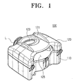
- FIG. 1 is a perspective view of a cyclone dust collecting apparatus of the present invention
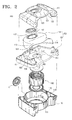
- FIG. 2 is an exploded view of the cyclone dust collecting apparatus of FIG. 1;
- FIG. 3 shows a lower side of a guide wall of FIG. 2
- FIG. 4 shows a lower side of a guide cover of FIG. 2
- FIG. 5 is a plan view of an operation state of the cyclone dust collecting apparatus of the present invention.
- FIG. 6 shows a lower side of a second embodiment of a guide wall according to the present invention.
- FIG. 7 is a graph showing changes in pressure loss between the cyclone dust collecting apparatus of the present invention and a conventional cyclone dust collecting apparatus.
- FIG. 8 is a lower side of a third embodiment of a guide wall according to the present invention.
- a cyclone dust collecting apparatus 100 of the present invention includes a cyclone main body 110, a guide unit 150, a cover member 120, and a filter unit 190.
- cyclone dust collecting apparatus 100 can include a locking member L for locking the cover member 120 and the cyclone main body 110 to one another.
- the cyclone main body 110 is internally partitioned with a cyclone chamber 111 and a dust collecting chamber 113.
- the cyclone main body 110 is shaped like a chamber having an open upper side.
- the cyclone chamber 111 is where a air drawn-in from outside of apparatus 100 through a first inlet 123 formed through the cover member 120 is rotated.
- the dust collecting chamber 113 is where that the dust separated by the centrifugal force in the rotated air is gathered.
- Upper sides of the cyclone chamber 111 and the dust collecting chamber 113 are closed by the later-mentioned guide unit 150 and the cover member 120.
- dust collecting chamber 113 comprises a plurality of dust collecting chambers 113 that enclose a part of the side outer wall of the cyclone chamber 111, as illustrated in FIG 5.
- the dust collecting chamber 113 is connected to the cyclone chamber 111 through a dust passage hole 115 penetrating through an inner wall of the cyclone chamber.
- the cover member 120 is formed on upper side of the cyclone main body 110, and includes the first inlet 123 and a first outlet 125.
- Cover member 120 can also include one or more handles 121.
- the first outlet 125 is a passage through which dust-free air from the cyclone chamber 111 is discharged. Since the first inlet 123 and the first outlet 125 are formed on the cover member 120, and the dust collecting chamber 113 is formed on a side outer wall of the cyclone chamber 111, the cyclone dust collecting apparatus 100 can be formed with a lower height than the conventional cyclone dust collecting apparatus, to accordingly achieve a compact-sized cyclone dust collecting apparatus 100.
- the guide unit 150 guides the drawn air into the cyclone chamber 111, and guides the air discharged from the cyclone chamber 111 towards the first outlet 125.
- the guide unit 150 includes a guide wall 160 partitioning the cover member 120 and the cyclone main body 110, and a guide cover 170.
- Cyclone dust collecting apparatus 100 can also include a sealing member 151 for sealing the space between the guide cover 170 and the first inlet 123.
- the guide wall 160 covers the upper sides of the cyclone chamber 111 and the dust collecting chambers 113, and includes a first side 161 facing the first inlet 123, a second side facing the cyclone chamber 111.
- the guide wall also includes a plurality of second inlets 163, a plurality of guide ducts 165, and a plurality of second outlets 169.
- the guide wall 160 closes the upper parts of the dust collecting chamber 113 and the cyclone chamber 111. By sealing the space between the cyclone chamber 111 and the guide wall 160, the air having gone through the guide wall may not flow back toward the first inlet 123.
- the plurality of second inlets 163 penetrate through the guide wall 160 to connect the cyclone chamber 111 to the first inlet 123, and guide the drawn air flown through the first inlet 123 into the cyclone chamber 111.
- the plurality of second inlets 163 may draw more air into the cyclone chamber 111 than the conventional cyclone dust collecting apparatus. Accordingly, it is possible to prevent suction force of the vacuum cleaner due to the cyclone dust collecting apparatus 100 from dropping, and consumption power from falling.
- the consumption power indicates work done by the vacuum cleaner under a predetermined condition.
- the consumption power is a term generally used as one example showing an efficiency of the cleaner in the related industry.
- the plurality of second inlets 163 comprise a pair of second inlets 163 provided.
- the drawn air flowing through the first inlet 123 is equally distributed and flown into the cyclone chamber 111 through the pair of second inlets 163.
- each second inlet 163 has a sloped part of the rim to guide the drawn air inward the guide ducts 165 in a sloped direction.
- the abovementioned second inlets 163 may be disposed outside an imaginary area (A) formed by straight lines connecting the first outlet 125 and the second outlets 169, which will be described later.
- the second inlets 163 are disposed further than the second outlets 169 from the first outlet 125.
- the plurality of guide ducts 165 each include a guide path 167 internally penetrating and a sloped plane 166 externally formed.
- the plurality of guide ducts 165 protrude on a second side of the guide wall 160 to correspond to each of the second inlets 163.
- the guide path 167 enhances rotary force of the drawn air flowing into the cyclone chamber 111, and minimizes the interference of the drawn air with the air inside the cyclone chamber 111.
- the guide path 167 has an outlet 168 thereof formed at a predetermined angle with respect to the second inlets 163 to guide the drawn air in a direction tangential to the cyclone chamber 111.
- the guide path 167 is spirally formed to guide the drawn air to rotate along an inner wall of the cyclone chamber 111, while the drawn air is gradually descending towards a lower part of the cyclone chamber.
- a sectional area of the guide path may be kept uniform along the direction of the drawn air proceeding toward the outlet 168 of the guide ducts 165 from the second inlets 163. Accordingly, it is possible to have uniform air flows inside the guide ducts, to minimize pressure loss caused by changes of proceeding direction of the drawn air as abovementioned.
- the sloped plane 166 is formed on one side facing a bottom side of the cyclone chamber 111 among outer circumference sides of the guide ducts 165. According to the embodiment of the present invention, the sloped plane 166 is bent considering the guide path 167 formed inside the guide ducts 165. The drawn air gets out of the guide path 167 and is guided to rotate downward along the inner wall of the cyclone chamber 111 by the sloped plane 166.
- the guide ducts 165 minimize the interference between the air rotating inside the cyclone chamber 111 and the air flown into the cyclone chamber 111, accordingly minimizing the pressure loss of the vacuum pressure due to the cyclone dust collecting apparatus 100.
- the second outlets 169 are a passage through which the drawn air having downwardly rotated and ascended is guided externally of the cyclone chamber 111. According to the embodiment of the present invention, on a lower part of the second outlets 169 are mounted with a filter unit to further separate minute dusts from the drawn air discharged from the cyclone chamber 111.
- the cyclone dust collecting apparatus 100 includes the guide cover 170 in order to prevent the first inlet 123 and the first outlet 125 from being mutually interfered.
- the guide cover 170 as illustrated in FIGS. 2 and 4, includes a partition wall 171 and a cutting unit 173. The partition wall 171 protrudes towards the guide wall 160 from an inner side of the guide cover 170.
- a lower part of the partition wall 171 blocks space between the second inlets 163 and the second outlets 169, when the guide cover 170 and the guide wall 160 are combined.
- the cutting unit 173 is formed by opening one end of the guide cover 170 facing the first outlet 125.
- the cutting unit 173 forms an outlet 174 connected to the first outlet 125, between the cutting unit 173 and the guide wall 160, when the guide cover 170 and the guide wall 160 are combined.
- internal space between the guide cover 170 and the guide wall 160 are partitioned with a first connection path 175 where the air flowing from the first inlet 123 passes and a second connection path 177 where the air discharged through the first outlet 125 passes.
- an external air is drawn through the first inlet 123.
- the air drawn through the first inlet 123 flows into the first connection path 175 through an inlet 172 of the guide cover 170 and is dispersed into the second inlets 163.
- the air dispersed into second inlets 163 passes through each guide paths formed inside each guide ducts 165, and flows into the cyclone chamber.
- the drawn air flowing into the cyclone chamber is guided to rotate downwardly along the inner wall of the cyclone chamber 111 by the guide paths 167.
- the drawn air discharges externally of the cyclone chamber 111 through the filter unit 190 and the second outlets 169.
- the drawn air discharged through the second outlets 169 consecutively passes through the second guide path 177, the outlet 174 of the second guide path 177 and the first outlet 125, and discharges externally of the cyclone dust collecting apparatus 100.
- dust (D) included in the drawn air are separated from the drawn air by centrifugal force generated when the drawn air rotates.
- the dust passes through the dust passage hole 115 and are housed in the dust collecting chamber 113.
- FIG. 6 shows a lower side of a guide wall 160' of a cyclone dust collecting apparatus according to the second embodiment of the present invention.
- the guide wall 160' is formed with three second inlets 163' and three guide ducts 165' corresponding thereto.
- the second inlets 163' are disposed radially with reference to second outlets 169 in the center, and equal spaced therebetween.
- the increased number of the second inlets 163' and the guide ducts 165' leads more drawn air drawn flowing into cyclone chamber 111 (refer to FIG. 1) than the first embodiment, during the same hour. Accordingly, pressure loss by the cyclone dust apparatus 100 (refer to FIG. 1) decreases.
- FIG. 7 illustrates comparison between the first and second embodiments, for pressure loss by the cyclone dust collecting apparatus 100 according to the number of the second inlets 163. 163', while motor forces, shapes of the second inlets 163, 163' and the guide ducts 165, 165' and shapes of the cyclone chamber are the same between two embodiments.
- the number of the second inlets 163, 163' increases, the more the pressure loss of the vacuum cleaner lowers.
- the number of the second inlets 163, 163' may be three.
- FIG. 8 shows a guide wall of a cyclone dust collecting apparatus according to a third embodiment of the present invention.
- the cyclone dust collecting apparatus 100 according to the embodiment of the present invention includes a first through three guide ducts 165a, 165b and 165c, and outlets 168a, 168b and 168c of each guide ducts 165a, 165b and 165c are differently shaped and located from the first and second embodiments.
- the outlets 168a, 168b and 168c of each guide ducts 165a, 165b and 165c are formed smaller, downward along the rotation direction B of the drawn air inside the cyclone chamber 111.
- the rotary force decreases.
- the decreased rotary force may be enhanced by making the drawn air flow quicker into the cyclone chamber 111 through the third guide duct 165a, than the drawn air discharged from the first guide duct 165a.
- one of the guide paths 167a, 167b and 167c overlaps with other guide duct along the direction further from the second side 162.
- a part of the second guide duct 165b overlaps with a part of the third guide duct 165c.
- Each space between the outlets 168a, 168b and 168c of the guide ducts 165a, 165b and 165c, and the second side 162 are different.
- the guide wall 160" and the guide cover 170 may have various changes in form where the drawn air rotates inside a first connection passage 175.
- the problem may be solved by making various changes in form and details for second inlets 163a, 163b and 163c, and the guide ducts 165a, 165b and 165c.
- an air flow inside a cyclone dust collecting apparatus through a first inlet is dispersed through a plurality of second inlets, and flows inside a cyclone chamber. It is possible to minimize pressure loss caused by the interference of the drawn air inside the cyclone chamber, to enhance cleaning efficiency of a vacuum cleaner.
- the drawn air having passed trough the plurality of second inlets is guided by a plurality of guide ducts spirally formed, and the rotary force of the drawn air decreases at the point when the drawn air enters into the cyclone chamber. Accordingly, dust collecting efficiencies are enhanced.
Landscapes
- Engineering & Computer Science (AREA)
- Mechanical Engineering (AREA)
- Filters For Electric Vacuum Cleaners (AREA)
- Cyclones (AREA)
Applications Claiming Priority (1)
| Application Number | Priority Date | Filing Date | Title |
|---|---|---|---|
| KR1020050102618A KR100721307B1 (ko) | 2005-10-28 | 2005-10-28 | 진공청소기의 집진장치 |
Publications (2)
| Publication Number | Publication Date |
|---|---|
| EP1779759A2 true EP1779759A2 (de) | 2007-05-02 |
| EP1779759A3 EP1779759A3 (de) | 2008-05-21 |
Family
ID=37654883
Family Applications (1)
| Application Number | Title | Priority Date | Filing Date |
|---|---|---|---|
| EP06290895A Withdrawn EP1779759A3 (de) | 2005-10-28 | 2006-06-01 | Staubsammler für Staubsauger |
Country Status (6)
| Country | Link |
|---|---|
| US (1) | US20070095034A1 (de) |
| EP (1) | EP1779759A3 (de) |
| KR (1) | KR100721307B1 (de) |
| CN (1) | CN1954763A (de) |
| AU (1) | AU2006201991B2 (de) |
| RU (1) | RU2332155C2 (de) |
Cited By (6)
| Publication number | Priority date | Publication date | Assignee | Title |
|---|---|---|---|---|
| GB2439169A (en) * | 2006-06-14 | 2007-12-19 | Panasonic Corp North America | A vacuum cleaner having a spiral air guide. |
| GB2450600A (en) * | 2007-06-29 | 2008-12-31 | Electrolux Home Care Prod Na | Vacuum cleaner |
| WO2014001496A1 (de) * | 2012-06-29 | 2014-01-03 | BSH Bosch und Siemens Hausgeräte GmbH | Staubsauger mit wirbelabscheider |
| CN103961027A (zh) * | 2014-04-23 | 2014-08-06 | 苏州科比电器有限公司 | 嵌入式吸尘器 |
| EP2820990A4 (de) * | 2012-02-29 | 2016-01-13 | Mitsubishi Electric Corp | Zyklonabscheider und elektrischer staubsauger |
| EP2659819A3 (de) * | 2012-05-03 | 2018-03-07 | BSH Hausgeräte GmbH | Staubsauger |
Families Citing this family (12)
| Publication number | Priority date | Publication date | Assignee | Title |
|---|---|---|---|---|
| US12220099B2 (en) | 2006-12-12 | 2025-02-11 | Omachron Intellectual Property Inc. | Surface cleaning apparatus |
| US11751733B2 (en) | 2007-08-29 | 2023-09-12 | Omachron Intellectual Property Inc. | Portable surface cleaning apparatus |
| US12048409B2 (en) | 2007-03-11 | 2024-07-30 | Omachron Intellectual Property Inc. | Portable surface cleaning apparatus |
| KR101471026B1 (ko) * | 2008-03-05 | 2014-12-11 | 삼성전자주식회사 | 먼지봉투 또는 사이클론 집진장치를 선택 장착할 수 있는진공청소기 |
| US7931740B2 (en) * | 2008-06-20 | 2011-04-26 | The Boeing Company | Cyclone separator |
| KR101065954B1 (ko) * | 2008-08-07 | 2011-09-19 | 엘지전자 주식회사 | 진공 청소기 |
| US9591952B2 (en) | 2009-03-11 | 2017-03-14 | Omachron Intellectual Property Inc. | Hand vacuum cleaner with removable dirt chamber |
| CA2917900C (en) | 2009-03-13 | 2019-01-08 | Omachron Intellectual Property Inc. | Portable surface cleaning apparatus |
| US11690489B2 (en) | 2009-03-13 | 2023-07-04 | Omachron Intellectual Property Inc. | Surface cleaning apparatus with an external dirt chamber |
| US9820622B2 (en) * | 2011-12-19 | 2017-11-21 | Koninklijke Philips N.V. | Cyclone vacuum cleaner and cyclone separation device |
| CN105246385B (zh) * | 2014-01-28 | 2017-08-11 | 皇家飞利浦有限公司 | 旋风分离装置 |
| US10786126B2 (en) | 2015-11-10 | 2020-09-29 | Techtronic Industries Co. Ltd. | Handheld vacuum cleaner |
Citations (1)
| Publication number | Priority date | Publication date | Assignee | Title |
|---|---|---|---|---|
| US6042628A (en) | 1996-11-12 | 2000-03-28 | Toyo Gijutsu Kogyo Co., Ltd. | Cyclone type dust collector |
Family Cites Families (19)
| Publication number | Priority date | Publication date | Assignee | Title |
|---|---|---|---|---|
| NL73070C (de) * | 1950-11-14 | |||
| US2848060A (en) * | 1956-09-13 | 1958-08-19 | Thermix Corp | Apparatus for separating mist particles or droplets from gases |
| US3034647A (en) * | 1959-06-25 | 1962-05-15 | Ametek Inc | Cyclone separator |
| US3925044A (en) * | 1971-03-19 | 1975-12-09 | Rockwell International Corp | Air filter |
| AU470888B2 (en) * | 1971-12-09 | 1976-04-01 | State Electricity Commission Of Victoria | Improvements in and relating to stream dividers |
| US3953184A (en) * | 1974-09-18 | 1976-04-27 | Stockford William F | Cyclone-type dust separator |
| US4162906A (en) * | 1977-05-05 | 1979-07-31 | Donaldson Company, Inc. | Side outlet tube |
| US4229194A (en) * | 1978-11-20 | 1980-10-21 | Atlantic Richfield Company | Vapor-solids separating device |
| US4308038A (en) * | 1979-05-10 | 1981-12-29 | Santek, Inc. | Inertial-electrostatic wet precipitator |
| HU179869B (en) * | 1980-05-29 | 1982-12-28 | Malom Es Suetoipari Kutatoin | Cyclone with double separation |
| KR20010026685A (ko) * | 1999-09-08 | 2001-04-06 | 구자홍 | 싸이클론 집진장치 |
| US6436160B1 (en) * | 2001-01-11 | 2002-08-20 | Royal Appliance Mfg. Co. | Dirt cup assembly for vacuum cleaner |
| KR100474078B1 (ko) * | 2003-06-02 | 2005-03-14 | 삼성광주전자 주식회사 | 진공청소기의 사이클론 집진장치 |
| KR100594194B1 (ko) * | 2003-09-30 | 2006-06-30 | 삼성광주전자 주식회사 | 진공청소기용 사이클론 집진장치 |
| GB0419002D0 (en) * | 2004-02-11 | 2004-09-29 | Samsung Gwanju Electronics Co | Cyclone dust-collecting apparatus |
| KR101064074B1 (ko) * | 2004-03-11 | 2011-09-08 | 엘지전자 주식회사 | 진공청소기의 집진어셈블리 |
| KR100533830B1 (ko) * | 2004-05-14 | 2005-12-07 | 삼성광주전자 주식회사 | 다중 사이클론 집진장치 |
| KR100661341B1 (ko) * | 2004-05-14 | 2006-12-27 | 삼성광주전자 주식회사 | 사이클론 집진장치 및 이를 포함한 진공청소기 |
| DE102004030350A1 (de) * | 2004-06-18 | 2006-01-12 | Alfred Kärcher Gmbh & Co. Kg | Staubsauger |
-
2005
- 2005-10-28 KR KR1020050102618A patent/KR100721307B1/ko not_active Expired - Fee Related
-
2006
- 2006-04-19 US US11/406,597 patent/US20070095034A1/en not_active Abandoned
- 2006-05-12 AU AU2006201991A patent/AU2006201991B2/en not_active Ceased
- 2006-05-25 RU RU2006117998/12A patent/RU2332155C2/ru not_active IP Right Cessation
- 2006-05-26 CN CNA2006100846330A patent/CN1954763A/zh active Pending
- 2006-06-01 EP EP06290895A patent/EP1779759A3/de not_active Withdrawn
Patent Citations (1)
| Publication number | Priority date | Publication date | Assignee | Title |
|---|---|---|---|---|
| US6042628A (en) | 1996-11-12 | 2000-03-28 | Toyo Gijutsu Kogyo Co., Ltd. | Cyclone type dust collector |
Cited By (11)
| Publication number | Priority date | Publication date | Assignee | Title |
|---|---|---|---|---|
| GB2439169A (en) * | 2006-06-14 | 2007-12-19 | Panasonic Corp North America | A vacuum cleaner having a spiral air guide. |
| GB2439169B (en) * | 2006-06-14 | 2009-06-24 | Panasonic Corp North America | Vacuum cleaner with spiral air guide |
| US7581287B2 (en) | 2006-06-14 | 2009-09-01 | Panasonic Corporation Of North America | Vacuum cleaner with spiral air guide |
| GB2450600A (en) * | 2007-06-29 | 2008-12-31 | Electrolux Home Care Prod Na | Vacuum cleaner |
| GB2460360A (en) * | 2007-06-29 | 2009-12-02 | Electrolux Home Prod Inc | Vacuum cleaner |
| GB2450600B (en) * | 2007-06-29 | 2010-01-06 | Electrolux Home Care Prod Na | Vacuum cleaner cleanout system |
| GB2460360B (en) * | 2007-06-29 | 2010-03-10 | Electrolux Home Prod Inc | Vacuum cleaner |
| EP2820990A4 (de) * | 2012-02-29 | 2016-01-13 | Mitsubishi Electric Corp | Zyklonabscheider und elektrischer staubsauger |
| EP2659819A3 (de) * | 2012-05-03 | 2018-03-07 | BSH Hausgeräte GmbH | Staubsauger |
| WO2014001496A1 (de) * | 2012-06-29 | 2014-01-03 | BSH Bosch und Siemens Hausgeräte GmbH | Staubsauger mit wirbelabscheider |
| CN103961027A (zh) * | 2014-04-23 | 2014-08-06 | 苏州科比电器有限公司 | 嵌入式吸尘器 |
Also Published As
| Publication number | Publication date |
|---|---|
| KR20070045857A (ko) | 2007-05-02 |
| RU2006117998A (ru) | 2007-12-10 |
| CN1954763A (zh) | 2007-05-02 |
| KR100721307B1 (ko) | 2007-05-28 |
| US20070095034A1 (en) | 2007-05-03 |
| EP1779759A3 (de) | 2008-05-21 |
| AU2006201991B2 (en) | 2008-09-18 |
| RU2332155C2 (ru) | 2008-08-27 |
| AU2006201991A1 (en) | 2007-05-17 |
Similar Documents
| Publication | Publication Date | Title |
|---|---|---|
| EP1779759A2 (de) | Staubsammler für Staubsauger | |
| EP1721556B1 (de) | Multi-Zyklon-Abscheider und Staubsauger mit demselben | |
| CN1839744B (zh) | 用于真空吸尘器的旋风灰尘分离设备和该真空吸尘器 | |
| KR101148125B1 (ko) | 사이클론 청소기 | |
| US20060230722A1 (en) | Multi-cyclone apparatus for vacuum cleaner | |
| KR100594194B1 (ko) | 진공청소기용 사이클론 집진장치 | |
| EP1714703B1 (de) | Zyklonabscheidevorrichtung und Staubsammelvorrichtung mit solch einer Abscheidevorrichtung | |
| US8308832B2 (en) | Dust separating and collecting apparatus of vacuum cleaner | |
| CN207412114U (zh) | 真空吸尘器 | |
| JP2005224602A (ja) | サイクロン集塵装置 | |
| JP2004358252A (ja) | サイクロン集塵装置およびそのサイクロン集塵装置を備えた真空掃除機用のハンドル組立体 | |
| EP1666154A2 (de) | Syklon-Staubabscheider | |
| KR102552903B1 (ko) | 청소기 | |
| CN113226139A (zh) | 集尘容器和清洁器 | |
| KR20060031359A (ko) | 사이클론 집진장치 | |
| JP2007117713A (ja) | 真空掃除機の集塵装置 | |
| JP2006320713A (ja) | マルチサイクロン集塵装置 | |
| EP3685725B1 (de) | Staubsammelvorrichtung und reiniger damit | |
| AU2017423525B2 (en) | Vacuum cleaner | |
| EP1952745A2 (de) | Staubsammelvorrichtung für einen Staubsauger | |
| KR100594579B1 (ko) | 사이클론 집진장치 | |
| CN101282674B (zh) | 用于真空吸尘器的灰尘收集装置 | |
| KR100606842B1 (ko) | 다중 사이클론 집진장치 | |
| EP1676517A2 (de) | Gerät zum Sammeln von Staub und Staubsauger mit diesem Gerät | |
| GB2424605A (en) | Multi-cyclone apparatus for a vacuum cleaner |
Legal Events
| Date | Code | Title | Description |
|---|---|---|---|
| PUAI | Public reference made under article 153(3) epc to a published international application that has entered the european phase |
Free format text: ORIGINAL CODE: 0009012 |
|
| AK | Designated contracting states |
Kind code of ref document: A2 Designated state(s): AT BE BG CH CY CZ DE DK EE ES FI FR GB GR HU IE IS IT LI LT LU LV MC NL PL PT RO SE SI SK TR |
|
| AX | Request for extension of the european patent |
Extension state: AL BA HR MK YU |
|
| PUAL | Search report despatched |
Free format text: ORIGINAL CODE: 0009013 |
|
| AK | Designated contracting states |
Kind code of ref document: A3 Designated state(s): AT BE BG CH CY CZ DE DK EE ES FI FR GB GR HU IE IS IT LI LT LU LV MC NL PL PT RO SE SI SK TR |
|
| AX | Request for extension of the european patent |
Extension state: AL BA HR MK YU |
|
| 17P | Request for examination filed |
Effective date: 20081016 |
|
| 17Q | First examination report despatched |
Effective date: 20081114 |
|
| AKX | Designation fees paid |
Designated state(s): DE ES FR GB IT |
|
| GRAP | Despatch of communication of intention to grant a patent |
Free format text: ORIGINAL CODE: EPIDOSNIGR1 |
|
| STAA | Information on the status of an ep patent application or granted ep patent |
Free format text: STATUS: THE APPLICATION IS DEEMED TO BE WITHDRAWN |
|
| 18D | Application deemed to be withdrawn |
Effective date: 20110101 |