EP1778986B1 - Pompe à metal en fusion - Google Patents
Pompe à metal en fusion Download PDFInfo
- Publication number
- EP1778986B1 EP1778986B1 EP05769567.8A EP05769567A EP1778986B1 EP 1778986 B1 EP1778986 B1 EP 1778986B1 EP 05769567 A EP05769567 A EP 05769567A EP 1778986 B1 EP1778986 B1 EP 1778986B1
- Authority
- EP
- European Patent Office
- Prior art keywords
- pump
- wall
- molten metal
- impeller
- opening
- Prior art date
- Legal status (The legal status is an assumption and is not a legal conclusion. Google has not performed a legal analysis and makes no representation as to the accuracy of the status listed.)
- Active
Links
- 229910052751 metal Inorganic materials 0.000 title claims description 121
- 239000002184 metal Substances 0.000 title claims description 121
- 238000002347 injection Methods 0.000 claims description 39
- 239000007924 injection Substances 0.000 claims description 39
- 239000000919 ceramic Substances 0.000 claims description 15
- 238000011144 upstream manufacturing Methods 0.000 claims description 11
- 238000004891 communication Methods 0.000 claims description 4
- 239000007789 gas Substances 0.000 description 66
- 230000008878 coupling Effects 0.000 description 24
- 238000010168 coupling process Methods 0.000 description 24
- 238000005859 coupling reaction Methods 0.000 description 24
- 239000012768 molten material Substances 0.000 description 13
- 239000000463 material Substances 0.000 description 12
- OKTJSMMVPCPJKN-UHFFFAOYSA-N Carbon Chemical compound [C] OKTJSMMVPCPJKN-UHFFFAOYSA-N 0.000 description 11
- 229910002804 graphite Inorganic materials 0.000 description 11
- 239000010439 graphite Substances 0.000 description 11
- 238000013461 design Methods 0.000 description 10
- 229910052782 aluminium Inorganic materials 0.000 description 9
- XAGFODPZIPBFFR-UHFFFAOYSA-N aluminium Chemical compound [Al] XAGFODPZIPBFFR-UHFFFAOYSA-N 0.000 description 9
- TWRXJAOTZQYOKJ-UHFFFAOYSA-L Magnesium chloride Chemical compound [Mg+2].[Cl-].[Cl-] TWRXJAOTZQYOKJ-UHFFFAOYSA-L 0.000 description 8
- 230000002093 peripheral effect Effects 0.000 description 7
- 238000005086 pumping Methods 0.000 description 7
- FYYHWMGAXLPEAU-UHFFFAOYSA-N Magnesium Chemical compound [Mg] FYYHWMGAXLPEAU-UHFFFAOYSA-N 0.000 description 6
- 229910052749 magnesium Inorganic materials 0.000 description 6
- 239000011777 magnesium Substances 0.000 description 6
- 230000007246 mechanism Effects 0.000 description 6
- 230000035515 penetration Effects 0.000 description 6
- ZAMOUSCENKQFHK-UHFFFAOYSA-N Chlorine atom Chemical compound [Cl] ZAMOUSCENKQFHK-UHFFFAOYSA-N 0.000 description 5
- 239000000460 chlorine Substances 0.000 description 5
- 229910052801 chlorine Inorganic materials 0.000 description 5
- 229910000831 Steel Inorganic materials 0.000 description 4
- 239000004568 cement Substances 0.000 description 4
- 229910001629 magnesium chloride Inorganic materials 0.000 description 4
- 238000004064 recycling Methods 0.000 description 4
- 239000010959 steel Substances 0.000 description 4
- 230000008901 benefit Effects 0.000 description 3
- 238000006243 chemical reaction Methods 0.000 description 3
- 238000004581 coalescence Methods 0.000 description 3
- 239000000945 filler Substances 0.000 description 3
- 238000000034 method Methods 0.000 description 3
- 238000012545 processing Methods 0.000 description 3
- 238000007670 refining Methods 0.000 description 3
- 239000011819 refractory material Substances 0.000 description 3
- 238000012546 transfer Methods 0.000 description 3
- XEEYBQQBJWHFJM-UHFFFAOYSA-N Iron Chemical compound [Fe] XEEYBQQBJWHFJM-UHFFFAOYSA-N 0.000 description 2
- 230000000712 assembly Effects 0.000 description 2
- 238000000429 assembly Methods 0.000 description 2
- 230000015572 biosynthetic process Effects 0.000 description 2
- 230000000295 complement effect Effects 0.000 description 2
- 239000006185 dispersion Substances 0.000 description 2
- -1 ferrous metals Chemical class 0.000 description 2
- 238000004519 manufacturing process Methods 0.000 description 2
- 239000007769 metal material Substances 0.000 description 2
- 230000003647 oxidation Effects 0.000 description 2
- 238000007254 oxidation reaction Methods 0.000 description 2
- 230000008569 process Effects 0.000 description 2
- 230000001681 protective effect Effects 0.000 description 2
- 230000009467 reduction Effects 0.000 description 2
- 230000007704 transition Effects 0.000 description 2
- 229910000838 Al alloy Inorganic materials 0.000 description 1
- UFHFLCQGNIYNRP-UHFFFAOYSA-N Hydrogen Chemical compound [H][H] UFHFLCQGNIYNRP-UHFFFAOYSA-N 0.000 description 1
- ATJFFYVFTNAWJD-UHFFFAOYSA-N Tin Chemical compound [Sn] ATJFFYVFTNAWJD-UHFFFAOYSA-N 0.000 description 1
- MUBKMWFYVHYZAI-UHFFFAOYSA-N [Al].[Cu].[Zn] Chemical compound [Al].[Cu].[Zn] MUBKMWFYVHYZAI-UHFFFAOYSA-N 0.000 description 1
- 229910045601 alloy Inorganic materials 0.000 description 1
- 239000000956 alloy Substances 0.000 description 1
- 238000005275 alloying Methods 0.000 description 1
- 238000002485 combustion reaction Methods 0.000 description 1
- 238000005336 cracking Methods 0.000 description 1
- 230000001419 dependent effect Effects 0.000 description 1
- 230000009977 dual effect Effects 0.000 description 1
- 230000000694 effects Effects 0.000 description 1
- 230000007613 environmental effect Effects 0.000 description 1
- 230000002349 favourable effect Effects 0.000 description 1
- 239000003779 heat-resistant material Substances 0.000 description 1
- 239000001257 hydrogen Substances 0.000 description 1
- 229910052739 hydrogen Inorganic materials 0.000 description 1
- 239000012535 impurity Substances 0.000 description 1
- 239000000411 inducer Substances 0.000 description 1
- 239000011261 inert gas Substances 0.000 description 1
- 229910052742 iron Inorganic materials 0.000 description 1
- 239000011133 lead Substances 0.000 description 1
- 238000003754 machining Methods 0.000 description 1
- 230000014759 maintenance of location Effects 0.000 description 1
- 230000013011 mating Effects 0.000 description 1
- 239000000155 melt Substances 0.000 description 1
- 238000002844 melting Methods 0.000 description 1
- 230000008018 melting Effects 0.000 description 1
- 150000002739 metals Chemical class 0.000 description 1
- 210000003739 neck Anatomy 0.000 description 1
- 230000010349 pulsation Effects 0.000 description 1
- 239000007787 solid Substances 0.000 description 1
- 239000011135 tin Substances 0.000 description 1
- XLYOFNOQVPJJNP-UHFFFAOYSA-N water Substances O XLYOFNOQVPJJNP-UHFFFAOYSA-N 0.000 description 1
- 238000003466 welding Methods 0.000 description 1
Images


Classifications
-
- F—MECHANICAL ENGINEERING; LIGHTING; HEATING; WEAPONS; BLASTING
- F04—POSITIVE - DISPLACEMENT MACHINES FOR LIQUIDS; PUMPS FOR LIQUIDS OR ELASTIC FLUIDS
- F04D—NON-POSITIVE-DISPLACEMENT PUMPS
- F04D7/00—Pumps adapted for handling specific fluids, e.g. by selection of specific materials for pumps or pump parts
- F04D7/02—Pumps adapted for handling specific fluids, e.g. by selection of specific materials for pumps or pump parts of centrifugal type
- F04D7/06—Pumps adapted for handling specific fluids, e.g. by selection of specific materials for pumps or pump parts of centrifugal type the fluids being hot or corrosive, e.g. liquid metals
- F04D7/065—Pumps adapted for handling specific fluids, e.g. by selection of specific materials for pumps or pump parts of centrifugal type the fluids being hot or corrosive, e.g. liquid metals for liquid metal
-
- F—MECHANICAL ENGINEERING; LIGHTING; HEATING; WEAPONS; BLASTING
- F04—POSITIVE - DISPLACEMENT MACHINES FOR LIQUIDS; PUMPS FOR LIQUIDS OR ELASTIC FLUIDS
- F04D—NON-POSITIVE-DISPLACEMENT PUMPS
- F04D29/00—Details, component parts, or accessories
- F04D29/60—Mounting; Assembling; Disassembling
- F04D29/62—Mounting; Assembling; Disassembling of radial or helico-centrifugal pumps
- F04D29/628—Mounting; Assembling; Disassembling of radial or helico-centrifugal pumps especially adapted for liquid pumps
-
- F—MECHANICAL ENGINEERING; LIGHTING; HEATING; WEAPONS; BLASTING
- F16—ENGINEERING ELEMENTS AND UNITS; GENERAL MEASURES FOR PRODUCING AND MAINTAINING EFFECTIVE FUNCTIONING OF MACHINES OR INSTALLATIONS; THERMAL INSULATION IN GENERAL
- F16D—COUPLINGS FOR TRANSMITTING ROTATION; CLUTCHES; BRAKES
- F16D1/00—Couplings for rigidly connecting two coaxial shafts or other movable machine elements
- F16D1/06—Couplings for rigidly connecting two coaxial shafts or other movable machine elements for attachment of a member on a shaft or on a shaft-end
- F16D1/08—Couplings for rigidly connecting two coaxial shafts or other movable machine elements for attachment of a member on a shaft or on a shaft-end with clamping hub; with hub and longitudinal key
- F16D1/0876—Couplings for rigidly connecting two coaxial shafts or other movable machine elements for attachment of a member on a shaft or on a shaft-end with clamping hub; with hub and longitudinal key with axial keys and no other radial clamping
- F16D1/0882—Couplings for rigidly connecting two coaxial shafts or other movable machine elements for attachment of a member on a shaft or on a shaft-end with clamping hub; with hub and longitudinal key with axial keys and no other radial clamping the key being axially tapered and tightening when loaded axially
-
- F—MECHANICAL ENGINEERING; LIGHTING; HEATING; WEAPONS; BLASTING
- F16—ENGINEERING ELEMENTS AND UNITS; GENERAL MEASURES FOR PRODUCING AND MAINTAINING EFFECTIVE FUNCTIONING OF MACHINES OR INSTALLATIONS; THERMAL INSULATION IN GENERAL
- F16D—COUPLINGS FOR TRANSMITTING ROTATION; CLUTCHES; BRAKES
- F16D1/00—Couplings for rigidly connecting two coaxial shafts or other movable machine elements
- F16D1/06—Couplings for rigidly connecting two coaxial shafts or other movable machine elements for attachment of a member on a shaft or on a shaft-end
- F16D1/08—Couplings for rigidly connecting two coaxial shafts or other movable machine elements for attachment of a member on a shaft or on a shaft-end with clamping hub; with hub and longitudinal key
- F16D1/0894—Couplings for rigidly connecting two coaxial shafts or other movable machine elements for attachment of a member on a shaft or on a shaft-end with clamping hub; with hub and longitudinal key with other than axial keys, e.g. diametral pins, cotter pins and no other radial clamping
Definitions
- a desired relationship between metal flow in the pump and the dimensions of the diffusing outlet may be provided.
- Q equals metal flow (in3/sec.) and Q/240 ⁇ (W, X H,) ⁇ Q/40.
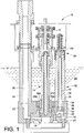
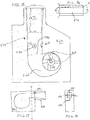
- the pump base housing 18 includes a vertical bore 44 that is dimensioned to receive the elongated rod 42 of the post assembly 32.
- the elongated rod 42 extends through the vertical bore 44 into a cavity 46.
- the rod 42 includes a threaded end 48 that cooperates with a nut 52, or other retaining member, to retain the threaded end 48 of the elongated rod 42 inside and to the base housing 18.
- the nut 52 can have an inclined face that cooperates with an inclined wall in the pump base housing 16 that defines an upper wall of the cavity 46.
- the base housing 18 Aligned with the vertical bore 44, the base housing 18 also includes a circular recess 54 that is dimensioned to receive the outer sheath 36.
- the outer sheath 36 and the retaining member 52 inhibit molten metal from the molten metal bath 28 from contacting the metal elongated rod 42.
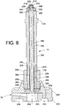
- a nut 214 and washer 216 can attach to an upper threaded end 218 of the elongated rod 172 to secure the key 212 vertically in place.
- a cotter pin 222 is received in a transverse throughbore adjacent the upper end of the elongated rod 172.
- a lower end of the impeller shaft assembly 14 attaches to the impeller 16.
- the impeller 16 includes a top structure 240 that attaches to a lower structure 242 using a key 244.
- the top structure 240 and the bottom structure 242 define vanes 246 through which the molten metal is pumped.
- the bottom structure 242 also includes an inlet 248 where molten metal enters the impeller.
- the impeller 16 depicted is a bottom inlet impeller; however, the impeller can take other configurations, such as a top inlet impeller.
- the depicted pump is a gas injection type but that any type of circulation or electromagnetic pump and in fact, any type of pump transporting molten metal may benefit by the inclusion of the present fan diffusing outlet design.
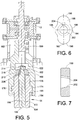
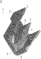
- Adapter 600 is comprised of a graphite, ceramic or other molten metal resistant body 601 having an inlet end 602, and an outlet end 604.
- the body 601 defines a passage 606 within which bifurcating fin 608 is positioned.
- the fin 108 is depicted as aligned along a longitudinal axis L of the adapter 600; however, the fin can be located elsewhere or could be curved if desired.
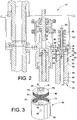
- a motor mount assembly 800 including among other elements, a primary support plate 803 to which the pump posts can be secured.
- Four threaded stud elements 805 are secured to the plate 803.
- Mounting ring 807 is positioned on stud elements 805 and the motor (not shown) secured thereto.
- Intermediate plate 803 and mounting ring 807, and positioned on studs 805, are adjustment elements 809.
- Adjustment elements 809 are constructed of tube element 811 , threaded adjustment cap 813 and locking ring 815.
- Adjustment cap 813 includes a threaded outer surface 817 suitable for mating with locking ring 815.
Claims (21)
- Pompe à métal en fusion (10) comprenant :un rotor (16) ;un boîtier de base de pompe (18) entourant au moins partiellement le rotor (16) ;un arbre (14) relié au rotor (16) ;un moteur (12) relié à l'arbre (14) ;une plaque de support de moteur (34) pour soutenir le moteur (12) ;un montant (32) pour relier la plaque de support de moteur (34) au boîtier de base de pompe (18),et un connecteur (60) reliant le montant (32) à la plaque de support de moteur (34) ;le connecteur (60) comprenant :une paroi latérale (62) ;une paroi interne (64) s'étendant depuis la paroi latérale (62) et comportant une ouverture alignée axialement (70), la paroi latérale (62) et la paroi interne (64) définissant un réceptacle inférieur (98) adapté pour recevoir le montant (32), caractérisée en ce quela paroi latérale (62) et la paroi interne (64) définissant un réceptacle supérieur adapté pour coopérer avec une plaque de support de moteur ou une structure (74) reliée à la plaque de support de moteur (34).
- Pompe de la revendication 1, dans laquelle l'ouverture (70) dans la paroi interne (64) est adaptée pour recevoir une tige allongée (42) qui est une composante de l'ensemble de montant (14).
- Pompe de la revendication 1 ou 2, comprenant en outre une structure de montage (74) adaptée pour être reliée au support de moteur (34) de la pompe à métal en fusion associée et pour être reçue à l'intérieur du réceptacle supérieur (72).
- Pompe de la revendication 3, dans laquelle la structure de montage (74) comporte des filetages externes (90) et la paroi latérale (62) comporte des filetages internes (92) dans le réceptacle supérieur (72).
- Pompe de la revendication 3, dans laquelle la structure de montage (74) comporte une ouverture (82) alignée avec l'ouverture (70) dans la paroi interne (64), où au moins l'une des ouvertures a une périphérie non circulaire.
- Pompe de l'une des revendications précédentes, dans laquelle la paroi latérale (62) comporte des ouvertures (68) adjacentes à la paroi interne (64).
- Pompe de l'une des revendications précédentes, dans laquelle la paroi latérale (62) comporte au moins une ouverture espacée de la paroi interne et débouchant dans le réceptacle inférieur (98).
- Pompe de la revendication 7, comprenant en outre un écrou de canon (142) dimensionné pour être reçu dans l'au moins une ouverture (140), l'écrou de canon comportant une ouverture filetée (146) qui est adaptée pour s'aligner avec l'ouverture dans la paroi interne (116).
- Pompe de la revendication 1, comprenant en outre un dispositif pour fournir une connexion réglable entre le montant (32) et la plaque de support de moteur (34) comprenant :une paroi latérale (62) définissant un réceptacle (98) dimensionné pour recevoir un montant (32) pour une pompe à métal en fusion associée ; etune partie supérieure (72) qui est adaptée pour être supportée de manière réglable sur un support de moteur ou une structure qui est reliée au support de moteur de la pompe à métal en fusion associée (10) pour permettre le réglage du dispositif dans un axe défini par l'axe longitudinal du montant pour la pompe à métal en fusion associée.
- Pompe de la revendication 9, dans laquelle la partie supérieure (72) du dispositif est filetée.
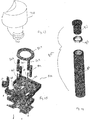
- Pompe de l'une des revendications précédentes, comprenant en outre un dispositif pour relier un arbre de rotor (14) à un moteur (12), le dispositif comprenant :une douille (162) adaptée pour se relier à un arbre d'entraînement (160) d'un moteur (12) d'une pompe à métal en fusion associée, la douille comportant une cavité étagée définissant une cavité supérieure (182) et une cavité inférieure (176), la cavité supérieure ayant une configuration non circulaire dans une section transversale prise perpendiculairement à un axe central de la douille, et la cavité inférieure étant adaptée pour recevoir un ensemble d'arbre de rotor (14) de la pompe à métal en fusion associée.
- Pompe de la revendication 11, comprenant en outre un connecteur d'arbre (188) ayant une ouverture centrale (202) pour recevoir une tige allongée (172) de l'ensemble d'arbre de rotor et une périphérie formée de sorte que la pompe d'arbre soit reçue de manière correspondante par la cavité supérieure (182) de sorte que la rotation de la douille (162) entraîne la rotation de la pompe d'arbre.
- Dispositif de la revendication 11 ou 12, comprenant en outre une clé pour verrouiller le connecteur d'arbre (188) sur la tige allongée (172).
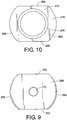
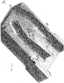
- Pompe de l'une des revendications précédentes, dans laquelle le rotor (16) comprend :un corps de forme généralement cylindrique ayant un axe de rotation ; etun élément de capuchon (300) fixé au corps et ayant une pluralité d'ouvertures d'entrée (306) communiquant avec des passages internes du corps, chaque ouverture d'entrée ayant une paroi intérieure (314) et une paroi extérieure (316), la paroi extérieure étant plus longue que la paroi intérieure, chaque ouverture d'entrée comportant également une paroi avant et une paroi arrière, la paroi avant (308) et la paroi arrière (312) interconnectant chacune la paroi intérieure et la paroi extérieure et étant chacune inclinée de sorte que le bord le plus haut de chaque paroi précède le bord le plus bas de chaque paroi dans une première direction de rotation.
- Pompe de la revendication 14, dans laquelle les ouvertures d'entrée (306) définissent l'un d'une pluralité de rayons radiaux en forme de barre, de rayons incurvés ou de rayons décalés radialement.
- Pompe de la revendication 14 ou 15, dans laquelle la paroi intérieure (314) de chaque ouverture d'entrée (306) est généralement parallèle à la paroi extérieure (316).
- Pompe de la revendication 14, 15 ou 16, dans laquelle la paroi avant (308) et la paroi arrière (312) sont planes ou concaves.
- Pompe de l'une des revendications précédentes, comportant un bouchon de tube d'injection de gaz (338) comprenant :un corps ayant un canal à travers lequel le gaz peut s'écouler, une partie du corps étant adaptée pour communiquer avec une source d'injection de gaz pour fournir du gaz au canal ; etun élément de pointe en céramique (368) disposé à l'intérieur du corps, l'élément de pointe en céramique comportant un passage en communication avec le canal.
- Pompe de la revendication 18, dans laquelle le corps comprend une partie en forme d'ailette (274) adaptée pour être disposée dans un écoulement de métal en fusion, où l'élément de pointe en céramique (368) s'étend depuis la partie en forme d'ailette.
- Pompe de la revendication 18, dans laquelle la forme du passage de sortie (332) est telle que le passage de sortie s'élargit dans une zone qui reçoit la partie en forme d'ailette.
- Pompe de l'une des revendications précédentes, comportant un adaptateur de sortie (600) comprenant un corps formant un passage dans lequel une ailette (608) est disposée à l'intérieur dudit passage de sortie, ladite ailette ayant une première extrémité ascendante conique et une deuxième extrémité avale conique reliées par une région généralement plus épaisse où les parois dudit passage de sortie divergent essentiellement au même degré d'augmentation que la conicité de la première extrémité de ladite ailette, et où un orifice d'injection de gaz s'étend à travers ladite ailette, sortant d'au moins une paroi latérale de celle-ci.
Priority Applications (1)
| Application Number | Priority Date | Filing Date | Title |
|---|---|---|---|
| EP16207575.8A EP3181916B1 (fr) | 2004-07-07 | 2005-07-07 | Pompe à metal en fusion |
Applications Claiming Priority (4)
| Application Number | Priority Date | Filing Date | Title |
|---|---|---|---|
| US58613404P | 2004-07-07 | 2004-07-07 | |
| US60764404P | 2004-09-07 | 2004-09-07 | |
| US67582805P | 2005-04-28 | 2005-04-28 | |
| PCT/US2005/024044 WO2006014517A2 (fr) | 2004-07-07 | 2005-07-07 | Pompe a metal en fusion |
Related Child Applications (1)
| Application Number | Title | Priority Date | Filing Date |
|---|---|---|---|
| EP16207575.8A Division EP3181916B1 (fr) | 2004-07-07 | 2005-07-07 | Pompe à metal en fusion |
Publications (3)
| Publication Number | Publication Date |
|---|---|
| EP1778986A2 EP1778986A2 (fr) | 2007-05-02 |
| EP1778986A4 EP1778986A4 (fr) | 2011-03-16 |
| EP1778986B1 true EP1778986B1 (fr) | 2017-01-04 |
Family
ID=35787635
Family Applications (2)
| Application Number | Title | Priority Date | Filing Date |
|---|---|---|---|
| EP16207575.8A Active EP3181916B1 (fr) | 2004-07-07 | 2005-07-07 | Pompe à metal en fusion |
| EP05769567.8A Active EP1778986B1 (fr) | 2004-07-07 | 2005-07-07 | Pompe à metal en fusion |
Family Applications Before (1)
| Application Number | Title | Priority Date | Filing Date |
|---|---|---|---|
| EP16207575.8A Active EP3181916B1 (fr) | 2004-07-07 | 2005-07-07 | Pompe à metal en fusion |
Country Status (8)
| Country | Link |
|---|---|
| US (2) | US9951777B2 (fr) |
| EP (2) | EP3181916B1 (fr) |
| JP (4) | JP4874243B2 (fr) |
| CA (3) | CA3051752C (fr) |
| ES (2) | ES2620735T3 (fr) |
| MX (1) | MX348717B (fr) |
| PL (1) | PL1778986T3 (fr) |
| WO (1) | WO2006014517A2 (fr) |
Families Citing this family (31)
| Publication number | Priority date | Publication date | Assignee | Title |
|---|---|---|---|---|
| US20070253807A1 (en) | 2006-04-28 | 2007-11-01 | Cooper Paul V | Gas-transfer foot |
| US9410744B2 (en) | 2010-05-12 | 2016-08-09 | Molten Metal Equipment Innovations, Llc | Vessel transfer insert and system |
| US8366993B2 (en) | 2007-06-21 | 2013-02-05 | Cooper Paul V | System and method for degassing molten metal |
| US8337746B2 (en) | 2007-06-21 | 2012-12-25 | Cooper Paul V | Transferring molten metal from one structure to another |
| US9205490B2 (en) | 2007-06-21 | 2015-12-08 | Molten Metal Equipment Innovations, Llc | Transfer well system and method for making same |
| US9643247B2 (en) | 2007-06-21 | 2017-05-09 | Molten Metal Equipment Innovations, Llc | Molten metal transfer and degassing system |
| US9409232B2 (en) | 2007-06-21 | 2016-08-09 | Molten Metal Equipment Innovations, Llc | Molten metal transfer vessel and method of construction |
| US9156087B2 (en) | 2007-06-21 | 2015-10-13 | Molten Metal Equipment Innovations, Llc | Molten metal transfer system and rotor |
| US10428821B2 (en) | 2009-08-07 | 2019-10-01 | Molten Metal Equipment Innovations, Llc | Quick submergence molten metal pump |
| US8524146B2 (en) | 2009-08-07 | 2013-09-03 | Paul V. Cooper | Rotary degassers and components therefor |
| US8535603B2 (en) | 2009-08-07 | 2013-09-17 | Paul V. Cooper | Rotary degasser and rotor therefor |
| US8444911B2 (en) | 2009-08-07 | 2013-05-21 | Paul V. Cooper | Shaft and post tensioning device |
| US9108244B2 (en) | 2009-09-09 | 2015-08-18 | Paul V. Cooper | Immersion heater for molten metal |
| AU2012245552B2 (en) * | 2011-04-18 | 2017-06-08 | Pyrotek, Inc. | Mold pump assembly |
| DE102011051961A1 (de) * | 2011-07-20 | 2013-01-24 | Zf Lenksysteme Gmbh | Vorrichtung zur Lagesicherung einer Einheit |
| PL220603B1 (pl) | 2012-03-31 | 2015-11-30 | Biopal Spółka Z Ograniczoną Odpowiedzialnością | Pompa ciekłego metalu dla obiegu grzewczego reaktora chemicznego |
| US9903383B2 (en) | 2013-03-13 | 2018-02-27 | Molten Metal Equipment Innovations, Llc | Molten metal rotor with hardened top |
| US9011761B2 (en) | 2013-03-14 | 2015-04-21 | Paul V. Cooper | Ladle with transfer conduit |
| US10052688B2 (en) | 2013-03-15 | 2018-08-21 | Molten Metal Equipment Innovations, Llc | Transfer pump launder system |
| KR101307447B1 (ko) * | 2013-04-10 | 2013-09-11 | 김형용 | 용탕펌프 |
| US20140363309A1 (en) * | 2013-06-07 | 2014-12-11 | Pyrotek, Inc, | Emergency molten metal pump out |
| US10465688B2 (en) | 2014-07-02 | 2019-11-05 | Molten Metal Equipment Innovations, Llc | Coupling and rotor shaft for molten metal devices |
| RU2589735C2 (ru) * | 2014-11-19 | 2016-07-10 | Открытое Акционерное Общество "Акмэ-Инжиниринг" | Насос для перекачки расплавленного металла |
| US10947980B2 (en) | 2015-02-02 | 2021-03-16 | Molten Metal Equipment Innovations, Llc | Molten metal rotor with hardened blade tips |
| US10267314B2 (en) | 2016-01-13 | 2019-04-23 | Molten Metal Equipment Innovations, Llc | Tensioned support shaft and other molten metal devices |
| MX2019001063A (es) * | 2016-07-25 | 2019-09-26 | Pyrotek Inc | Bomba de inyeccion de gas de metal fundido con salida abierta. |
| EP3655658B1 (fr) * | 2017-07-20 | 2022-03-23 | Pyrotek, Inc. | Appareil d'engagement de pompe de moule et procede de remplissage d'un moule |
| US11149747B2 (en) | 2017-11-17 | 2021-10-19 | Molten Metal Equipment Innovations, Llc | Tensioned support post and other molten metal devices |
| US11358216B2 (en) | 2019-05-17 | 2022-06-14 | Molten Metal Equipment Innovations, Llc | System for melting solid metal |
| CA3216159A1 (fr) * | 2021-04-23 | 2022-10-27 | Andrew Horsfall | Ensembles arbre et montant pour appareil pour matiere fondue |
| US11873845B2 (en) | 2021-05-28 | 2024-01-16 | Molten Metal Equipment Innovations, Llc | Molten metal transfer device |
Family Cites Families (47)
| Publication number | Priority date | Publication date | Assignee | Title |
|---|---|---|---|---|
| FR2182623B1 (fr) * | 1972-03-30 | 1974-12-20 | Activite Atom Avance | |
| US4052199A (en) * | 1975-07-21 | 1977-10-04 | The Carborundum Company | Gas injection method |
| FR2358576A1 (fr) * | 1976-07-12 | 1978-02-10 | Robot Coupe Sa | Dispositif de fixation d'outils sur l'axe d'un moteur, notamment pour appareils electromenagers |
| US4169584A (en) | 1977-07-18 | 1979-10-02 | The Carborundum Company | Gas injection apparatus |
| JPS63120897A (ja) * | 1986-11-10 | 1988-05-25 | Matsuda Pump Seisakusho:Kk | セラミツク製溶融金属ポンプ |
| EP0286809B1 (fr) * | 1987-04-10 | 1991-10-16 | Rockwell International Corporation | Roue d'aspiration réfractaire à la cavitation |
| US5092821A (en) * | 1990-01-18 | 1992-03-03 | The Carborundum Company | Drive system for impeller shafts |
| JPH03164594A (ja) * | 1990-10-30 | 1991-07-16 | Matsuda Pump Seisakusho:Kk | セラミック製溶融金属ポンプ |
| CA2097648C (fr) * | 1992-06-12 | 1998-04-28 | Ronald E. Gilbert | Pompe a metal en fusion avec roue a palettes et chambre de pompage dirigeant le debit |
| DE4221705A1 (de) * | 1992-07-02 | 1994-01-05 | Voith Gmbh J M | Hydrostatische Maschine mit axialem Schubausgleich |
| US5662725A (en) * | 1995-05-12 | 1997-09-02 | Cooper; Paul V. | System and device for removing impurities from molten metal |
| US5685701A (en) * | 1995-06-01 | 1997-11-11 | Metaullics Systems Co., L.P. | Bearing arrangement for molten aluminum pumps |
| US5735668A (en) * | 1996-03-04 | 1998-04-07 | Ansimag Inc. | Axial bearing having independent pads for a centrifugal pump |
| DE69722878T2 (de) * | 1996-04-23 | 2003-12-04 | Metaullics Systems Co | Laufrad für flüssigmetallpumpen |
| WO1998004372A1 (fr) * | 1996-07-26 | 1998-02-05 | Metaullics Systems Co., L.P. | Pompe de gazage |
| US6254340B1 (en) | 1997-04-23 | 2001-07-03 | Metaullics Systems Co., L.P. | Molten metal impeller |
| US6019576A (en) * | 1997-09-22 | 2000-02-01 | Thut; Bruno H. | Pumps for pumping molten metal with a stirring action |
| US6071074A (en) | 1998-08-07 | 2000-06-06 | Alphatech, Inc. | Advanced motor driven impeller pump for moving metal in a bath of molten metal |
| US6093000A (en) * | 1998-08-11 | 2000-07-25 | Cooper; Paul V | Molten metal pump with monolithic rotor |
| US6887425B2 (en) * | 1998-11-09 | 2005-05-03 | Metaullics Systems Co., L.P. | Shaft and post assemblies for molten metal apparatus |
| ES2277300T3 (es) | 1998-11-09 | 2007-07-01 | Pyrotek, Inc. | Conjuntos de eje y poste para aparato de bombeo de metal fundido. |
| JP4081889B2 (ja) * | 1998-11-11 | 2008-04-30 | 日産自動車株式会社 | 電動車両の強電ハーネス配索構造 |
| JP3891533B2 (ja) * | 1998-11-16 | 2007-03-14 | アイシン・エィ・ダブリュ株式会社 | 駆動装置 |
| US6303074B1 (en) * | 1999-05-14 | 2001-10-16 | Paul V. Cooper | Mixed flow rotor for molten metal pumping device |
| US6457940B1 (en) * | 1999-07-23 | 2002-10-01 | Dale T. Lehman | Molten metal pump |
| US6439860B1 (en) | 1999-11-22 | 2002-08-27 | Karl Greer | Chambered vane impeller molten metal pump |
| US6562286B1 (en) | 2000-03-13 | 2003-05-13 | Dale T. Lehman | Post mounting system and method for molten metal pump |
| US6524006B1 (en) * | 2000-04-11 | 2003-02-25 | International Business Machines Corporation | Fluid dynamic bearing assembly |
| JP3843702B2 (ja) * | 2000-06-09 | 2006-11-08 | アイシン・エィ・ダブリュ株式会社 | 電動車両駆動用駆動装置 |
| US6524066B2 (en) * | 2001-01-31 | 2003-02-25 | Bruno H. Thut | Impeller for molten metal pump with reduced clogging |
| US6533535B2 (en) * | 2001-04-06 | 2003-03-18 | Bruno H. Thut | Molten metal pump with protected inlet |
| JP4159797B2 (ja) * | 2001-05-10 | 2008-10-01 | 株式会社ミツバ | 電動モータ |
| US6709234B2 (en) * | 2001-08-31 | 2004-03-23 | Pyrotek, Inc. | Impeller shaft assembly system |
| WO2003085814A1 (fr) * | 2002-04-04 | 2003-10-16 | Hitachi, Ltd. | Convertisseur de puissance, systeme d'alimentation equipe de celui-ci et corps mobile |
| JP2003311398A (ja) * | 2002-04-16 | 2003-11-05 | Nihon Dennetsu Keiki Co Ltd | 鉛フリーはんだ用誘導型電磁ポンプ |
| US7402276B2 (en) * | 2003-07-14 | 2008-07-22 | Cooper Paul V | Pump with rotating inlet |
| JP4014152B2 (ja) * | 2002-10-09 | 2007-11-28 | 本田技研工業株式会社 | 電気車両用パワーコントロールユニット |
| US6869564B2 (en) * | 2002-10-29 | 2005-03-22 | Pyrotek, Inc. | Molten metal pump system |
| US6918741B2 (en) * | 2002-11-15 | 2005-07-19 | Pyrotek, Inc. | Molten metal pump impeller system |
| JP3858841B2 (ja) * | 2003-03-20 | 2006-12-20 | トヨタ自動車株式会社 | ハイブリッド車両 |
| JP2005253167A (ja) * | 2004-03-03 | 2005-09-15 | Hitachi Ltd | 車両駆動装置及びそれを用いた電動4輪駆動車両 |
| US7476357B2 (en) * | 2004-12-02 | 2009-01-13 | Thut Bruno H | Gas mixing and dispersement in pumps for pumping molten metal |
| US7326028B2 (en) * | 2005-04-28 | 2008-02-05 | Morando Jorge A | High flow/dual inducer/high efficiency impeller for liquid applications including molten metal |
| US9599111B2 (en) * | 2008-10-29 | 2017-03-21 | Jorge A. Morando | Riserless recirculation/transfer pump and mixer/pre-melter for molten metal applications |
| US9458724B2 (en) * | 2010-07-02 | 2016-10-04 | Pyrotek, Inc. | Molten metal impeller |
| US9903383B2 (en) * | 2013-03-13 | 2018-02-27 | Molten Metal Equipment Innovations, Llc | Molten metal rotor with hardened top |
| EP3309401B1 (fr) * | 2016-10-17 | 2019-12-04 | Xylem Europe GmbH | Procédé permettant de fournir un espace axial situé dans un ensemble de coupe d'une pompe de rectifieuse et pompe de rectifieuse comprenant une cale conçue pour fournir ledit interstice axial |
-
2005
- 2005-07-07 WO PCT/US2005/024044 patent/WO2006014517A2/fr active Application Filing
- 2005-07-07 ES ES05769567.8T patent/ES2620735T3/es active Active
- 2005-07-07 CA CA3051752A patent/CA3051752C/fr active Active
- 2005-07-07 CA CA2948335A patent/CA2948335C/fr active Active
- 2005-07-07 PL PL05769567T patent/PL1778986T3/pl unknown
- 2005-07-07 US US11/631,885 patent/US9951777B2/en active Active
- 2005-07-07 EP EP16207575.8A patent/EP3181916B1/fr active Active
- 2005-07-07 CA CA2573137A patent/CA2573137C/fr active Active
- 2005-07-07 EP EP05769567.8A patent/EP1778986B1/fr active Active
- 2005-07-07 JP JP2007520484A patent/JP4874243B2/ja active Active
- 2005-07-07 MX MX2007000047A patent/MX348717B/es active IP Right Grant
- 2005-07-07 ES ES16207575T patent/ES2857580T3/es active Active
-
2011
- 2011-04-05 JP JP2011083416A patent/JP5562282B2/ja active Active
-
2013
- 2013-03-05 JP JP2013042688A patent/JP5684305B2/ja active Active
-
2014
- 2014-08-04 JP JP2014158978A patent/JP5941950B2/ja active Active
-
2017
- 2017-11-16 US US15/814,479 patent/US11131309B2/en active Active
Non-Patent Citations (1)
| Title |
|---|
| None * |
Also Published As
| Publication number | Publication date |
|---|---|
| PL1778986T3 (pl) | 2017-08-31 |
| JP2008506067A (ja) | 2008-02-28 |
| ES2857580T3 (es) | 2021-09-29 |
| CA2948335C (fr) | 2019-09-17 |
| JP5684305B2 (ja) | 2015-03-11 |
| JP5562282B2 (ja) | 2014-07-30 |
| JP4874243B2 (ja) | 2012-02-15 |
| JP5941950B2 (ja) | 2016-06-29 |
| US9951777B2 (en) | 2018-04-24 |
| EP1778986A4 (fr) | 2011-03-16 |
| CA2573137A1 (fr) | 2006-02-09 |
| CA3051752C (fr) | 2021-12-14 |
| MX2007000047A (es) | 2007-03-27 |
| EP3181916B1 (fr) | 2021-01-27 |
| EP3181916A3 (fr) | 2017-11-08 |
| CA3051752A1 (fr) | 2006-02-09 |
| CA2948335A1 (fr) | 2006-02-09 |
| CA2573137C (fr) | 2016-11-15 |
| EP1778986A2 (fr) | 2007-05-02 |
| WO2006014517A2 (fr) | 2006-02-09 |
| US20080253905A1 (en) | 2008-10-16 |
| MX348717B (es) | 2017-06-27 |
| US11131309B2 (en) | 2021-09-28 |
| JP2014224541A (ja) | 2014-12-04 |
| JP2013148097A (ja) | 2013-08-01 |
| US20180187685A1 (en) | 2018-07-05 |
| JP2011132964A (ja) | 2011-07-07 |
| EP3181916A2 (fr) | 2017-06-21 |
| ES2620735T3 (es) | 2017-06-29 |
| WO2006014517A3 (fr) | 2006-04-20 |
Similar Documents
| Publication | Publication Date | Title |
|---|---|---|
| EP1778986B1 (fr) | Pompe à metal en fusion | |
| US11391293B2 (en) | Molten metal rotor with hardened top | |
| US20190360491A1 (en) | Coupling and rotor shaft for molten metal devices | |
| US7476357B2 (en) | Gas mixing and dispersement in pumps for pumping molten metal | |
| US10947980B2 (en) | Molten metal rotor with hardened blade tips | |
| US5685701A (en) | Bearing arrangement for molten aluminum pumps | |
| US6398525B1 (en) | Monolithic rotor and rigid coupling | |
| EP2729748B1 (fr) | Système d'immersion de déchet | |
| US6723276B1 (en) | Scrap melter and impeller | |
| US8449814B2 (en) | Systems and methods for melting scrap metal | |
| US8529828B2 (en) | Molten metal pump components | |
| US7731891B2 (en) | Couplings for molten metal devices | |
| US20060180963A1 (en) | Vortexer apparatus | |
| US6755614B1 (en) | Molten metal pump impeller |
Legal Events
| Date | Code | Title | Description |
|---|---|---|---|
| PUAI | Public reference made under article 153(3) epc to a published international application that has entered the european phase |
Free format text: ORIGINAL CODE: 0009012 |
|
| 17P | Request for examination filed |
Effective date: 20070207 |
|
| AK | Designated contracting states |
Kind code of ref document: A2 Designated state(s): AT BE BG CH CY CZ DE DK EE ES FI FR GB GR HU IE IS IT LI LT LU LV MC NL PL PT RO SE SI SK TR |
|
| DAX | Request for extension of the european patent (deleted) | ||
| RIN1 | Information on inventor provided before grant (corrected) |
Inventor name: MORDUE, GEORGE Inventor name: TIPTON, JON Inventor name: VILD, CHRIS, T. Inventor name: LUTES, LENNARD Inventor name: BRIGHT, MARK Inventor name: HENDERSON, RICHARD, S. Inventor name: MORANDO, JORGE, A. |
|
| RIN1 | Information on inventor provided before grant (corrected) |
Inventor name: BRIGHT, MARK Inventor name: MORDUE, GEORGE Inventor name: TIPTON, JON Inventor name: VILD, CHRIS, T. Inventor name: HENDERSON, RICHARD, S. Inventor name: MORANDO, JORGE, A. Inventor name: LUTES, LENNARD |
|
| A4 | Supplementary search report drawn up and despatched |
Effective date: 20110216 |
|
| 17Q | First examination report despatched |
Effective date: 20121019 |
|
| GRAP | Despatch of communication of intention to grant a patent |
Free format text: ORIGINAL CODE: EPIDOSNIGR1 |
|
| INTG | Intention to grant announced |
Effective date: 20160719 |
|
| GRAS | Grant fee paid |
Free format text: ORIGINAL CODE: EPIDOSNIGR3 |
|
| GRAA | (expected) grant |
Free format text: ORIGINAL CODE: 0009210 |
|
| AK | Designated contracting states |
Kind code of ref document: B1 Designated state(s): AT BE BG CH CY CZ DE DK EE ES FI FR GB GR HU IE IS IT LI LT LU LV MC NL PL PT RO SE SI SK TR |
|
| REG | Reference to a national code |
Ref country code: GB Ref legal event code: FG4D |
|
| REG | Reference to a national code |
Ref country code: CH Ref legal event code: EP |
|
| REG | Reference to a national code |
Ref country code: AT Ref legal event code: REF Ref document number: 859533 Country of ref document: AT Kind code of ref document: T Effective date: 20170115 |
|
| REG | Reference to a national code |
Ref country code: IE Ref legal event code: FG4D |
|
| REG | Reference to a national code |
Ref country code: DE Ref legal event code: R096 Ref document number: 602005051075 Country of ref document: DE |
|
| REG | Reference to a national code |
Ref country code: DE Ref legal event code: R082 Ref document number: 602005051075 Country of ref document: DE Representative=s name: MEISSNER BOLTE PATENTANWAELTE RECHTSANWAELTE P, DE |
|
| REG | Reference to a national code |
Ref country code: NL Ref legal event code: FP |
|
| REG | Reference to a national code |
Ref country code: LT Ref legal event code: MG4D |
|
| REG | Reference to a national code |
Ref country code: AT Ref legal event code: MK05 Ref document number: 859533 Country of ref document: AT Kind code of ref document: T Effective date: 20170104 |
|
| REG | Reference to a national code |
Ref country code: FR Ref legal event code: PLFP Year of fee payment: 13 |
|
| REG | Reference to a national code |
Ref country code: ES Ref legal event code: FG2A Ref document number: 2620735 Country of ref document: ES Kind code of ref document: T3 Effective date: 20170629 |
|
| PG25 | Lapsed in a contracting state [announced via postgrant information from national office to epo] |
Ref country code: IS Free format text: LAPSE BECAUSE OF FAILURE TO SUBMIT A TRANSLATION OF THE DESCRIPTION OR TO PAY THE FEE WITHIN THE PRESCRIBED TIME-LIMIT Effective date: 20170504 Ref country code: FI Free format text: LAPSE BECAUSE OF FAILURE TO SUBMIT A TRANSLATION OF THE DESCRIPTION OR TO PAY THE FEE WITHIN THE PRESCRIBED TIME-LIMIT Effective date: 20170104 Ref country code: LT Free format text: LAPSE BECAUSE OF FAILURE TO SUBMIT A TRANSLATION OF THE DESCRIPTION OR TO PAY THE FEE WITHIN THE PRESCRIBED TIME-LIMIT Effective date: 20170104 |
|
| PG25 | Lapsed in a contracting state [announced via postgrant information from national office to epo] |
Ref country code: BG Free format text: LAPSE BECAUSE OF FAILURE TO SUBMIT A TRANSLATION OF THE DESCRIPTION OR TO PAY THE FEE WITHIN THE PRESCRIBED TIME-LIMIT Effective date: 20170404 Ref country code: AT Free format text: LAPSE BECAUSE OF FAILURE TO SUBMIT A TRANSLATION OF THE DESCRIPTION OR TO PAY THE FEE WITHIN THE PRESCRIBED TIME-LIMIT Effective date: 20170104 Ref country code: SE Free format text: LAPSE BECAUSE OF FAILURE TO SUBMIT A TRANSLATION OF THE DESCRIPTION OR TO PAY THE FEE WITHIN THE PRESCRIBED TIME-LIMIT Effective date: 20170104 Ref country code: PT Free format text: LAPSE BECAUSE OF FAILURE TO SUBMIT A TRANSLATION OF THE DESCRIPTION OR TO PAY THE FEE WITHIN THE PRESCRIBED TIME-LIMIT Effective date: 20170504 Ref country code: LV Free format text: LAPSE BECAUSE OF FAILURE TO SUBMIT A TRANSLATION OF THE DESCRIPTION OR TO PAY THE FEE WITHIN THE PRESCRIBED TIME-LIMIT Effective date: 20170104 |
|
| REG | Reference to a national code |
Ref country code: DE Ref legal event code: R097 Ref document number: 602005051075 Country of ref document: DE |
|
| PG25 | Lapsed in a contracting state [announced via postgrant information from national office to epo] |
Ref country code: SK Free format text: LAPSE BECAUSE OF FAILURE TO SUBMIT A TRANSLATION OF THE DESCRIPTION OR TO PAY THE FEE WITHIN THE PRESCRIBED TIME-LIMIT Effective date: 20170104 Ref country code: EE Free format text: LAPSE BECAUSE OF FAILURE TO SUBMIT A TRANSLATION OF THE DESCRIPTION OR TO PAY THE FEE WITHIN THE PRESCRIBED TIME-LIMIT Effective date: 20170104 Ref country code: RO Free format text: LAPSE BECAUSE OF FAILURE TO SUBMIT A TRANSLATION OF THE DESCRIPTION OR TO PAY THE FEE WITHIN THE PRESCRIBED TIME-LIMIT Effective date: 20170104 |
|
| REG | Reference to a national code |
Ref country code: GR Ref legal event code: EP Ref document number: 20170400995 Country of ref document: GR Effective date: 20171023 |
|
| PLBE | No opposition filed within time limit |
Free format text: ORIGINAL CODE: 0009261 |
|
| STAA | Information on the status of an ep patent application or granted ep patent |
Free format text: STATUS: NO OPPOSITION FILED WITHIN TIME LIMIT |
|
| PG25 | Lapsed in a contracting state [announced via postgrant information from national office to epo] |
Ref country code: DK Free format text: LAPSE BECAUSE OF FAILURE TO SUBMIT A TRANSLATION OF THE DESCRIPTION OR TO PAY THE FEE WITHIN THE PRESCRIBED TIME-LIMIT Effective date: 20170104 |
|
| 26N | No opposition filed |
Effective date: 20171005 |
|
| PG25 | Lapsed in a contracting state [announced via postgrant information from national office to epo] |
Ref country code: SI Free format text: LAPSE BECAUSE OF FAILURE TO SUBMIT A TRANSLATION OF THE DESCRIPTION OR TO PAY THE FEE WITHIN THE PRESCRIBED TIME-LIMIT Effective date: 20170104 |
|
| REG | Reference to a national code |
Ref country code: CH Ref legal event code: PL |
|
| REG | Reference to a national code |
Ref country code: IE Ref legal event code: MM4A |
|
| PG25 | Lapsed in a contracting state [announced via postgrant information from national office to epo] |
Ref country code: CH Free format text: LAPSE BECAUSE OF NON-PAYMENT OF DUE FEES Effective date: 20170731 Ref country code: LI Free format text: LAPSE BECAUSE OF NON-PAYMENT OF DUE FEES Effective date: 20170731 Ref country code: IE Free format text: LAPSE BECAUSE OF NON-PAYMENT OF DUE FEES Effective date: 20170707 |
|
| REG | Reference to a national code |
Ref country code: FR Ref legal event code: PLFP Year of fee payment: 14 |
|
| PG25 | Lapsed in a contracting state [announced via postgrant information from national office to epo] |
Ref country code: LU Free format text: LAPSE BECAUSE OF NON-PAYMENT OF DUE FEES Effective date: 20170707 |
|
| PG25 | Lapsed in a contracting state [announced via postgrant information from national office to epo] |
Ref country code: HU Free format text: LAPSE BECAUSE OF FAILURE TO SUBMIT A TRANSLATION OF THE DESCRIPTION OR TO PAY THE FEE WITHIN THE PRESCRIBED TIME-LIMIT; INVALID AB INITIO Effective date: 20050707 Ref country code: MC Free format text: LAPSE BECAUSE OF FAILURE TO SUBMIT A TRANSLATION OF THE DESCRIPTION OR TO PAY THE FEE WITHIN THE PRESCRIBED TIME-LIMIT Effective date: 20170104 |
|
| PG25 | Lapsed in a contracting state [announced via postgrant information from national office to epo] |
Ref country code: CY Free format text: LAPSE BECAUSE OF NON-PAYMENT OF DUE FEES Effective date: 20170104 |
|
| PGFP | Annual fee paid to national office [announced via postgrant information from national office to epo] |
Ref country code: NL Payment date: 20230619 Year of fee payment: 19 Ref country code: FR Payment date: 20230616 Year of fee payment: 19 Ref country code: CZ Payment date: 20230620 Year of fee payment: 19 |
|
| PGFP | Annual fee paid to national office [announced via postgrant information from national office to epo] |
Ref country code: PL Payment date: 20230619 Year of fee payment: 19 Ref country code: GR Payment date: 20230626 Year of fee payment: 19 |
|
| PGFP | Annual fee paid to national office [announced via postgrant information from national office to epo] |
Ref country code: BE Payment date: 20230616 Year of fee payment: 19 |
|
| PGFP | Annual fee paid to national office [announced via postgrant information from national office to epo] |
Ref country code: TR Payment date: 20230705 Year of fee payment: 19 Ref country code: IT Payment date: 20230711 Year of fee payment: 19 Ref country code: GB Payment date: 20230614 Year of fee payment: 19 Ref country code: ES Payment date: 20230802 Year of fee payment: 19 |
|
| PGFP | Annual fee paid to national office [announced via postgrant information from national office to epo] |
Ref country code: DE Payment date: 20230614 Year of fee payment: 19 |