EP1778986B1 - Molten metal pump - Google Patents
Molten metal pump Download PDFInfo
- Publication number
- EP1778986B1 EP1778986B1 EP05769567.8A EP05769567A EP1778986B1 EP 1778986 B1 EP1778986 B1 EP 1778986B1 EP 05769567 A EP05769567 A EP 05769567A EP 1778986 B1 EP1778986 B1 EP 1778986B1
- Authority
- EP
- European Patent Office
- Prior art keywords
- pump
- wall
- molten metal
- impeller
- opening
- Prior art date
- Legal status (The legal status is an assumption and is not a legal conclusion. Google has not performed a legal analysis and makes no representation as to the accuracy of the status listed.)
- Active
Links
- 229910052751 metal Inorganic materials 0.000 title claims description 121
- 239000002184 metal Substances 0.000 title claims description 121
- 238000002347 injection Methods 0.000 claims description 39
- 239000007924 injection Substances 0.000 claims description 39
- 239000000919 ceramic Substances 0.000 claims description 15
- 238000011144 upstream manufacturing Methods 0.000 claims description 11
- 238000004891 communication Methods 0.000 claims description 4
- 239000007789 gas Substances 0.000 description 66
- 230000008878 coupling Effects 0.000 description 24
- 238000010168 coupling process Methods 0.000 description 24
- 238000005859 coupling reaction Methods 0.000 description 24
- 239000012768 molten material Substances 0.000 description 13
- 239000000463 material Substances 0.000 description 12
- OKTJSMMVPCPJKN-UHFFFAOYSA-N Carbon Chemical compound [C] OKTJSMMVPCPJKN-UHFFFAOYSA-N 0.000 description 11
- 229910002804 graphite Inorganic materials 0.000 description 11
- 239000010439 graphite Substances 0.000 description 11
- 238000013461 design Methods 0.000 description 10
- 229910052782 aluminium Inorganic materials 0.000 description 9
- XAGFODPZIPBFFR-UHFFFAOYSA-N aluminium Chemical compound [Al] XAGFODPZIPBFFR-UHFFFAOYSA-N 0.000 description 9
- TWRXJAOTZQYOKJ-UHFFFAOYSA-L Magnesium chloride Chemical compound [Mg+2].[Cl-].[Cl-] TWRXJAOTZQYOKJ-UHFFFAOYSA-L 0.000 description 8
- 230000002093 peripheral effect Effects 0.000 description 7
- 238000005086 pumping Methods 0.000 description 7
- FYYHWMGAXLPEAU-UHFFFAOYSA-N Magnesium Chemical compound [Mg] FYYHWMGAXLPEAU-UHFFFAOYSA-N 0.000 description 6
- 229910052749 magnesium Inorganic materials 0.000 description 6
- 239000011777 magnesium Substances 0.000 description 6
- 230000007246 mechanism Effects 0.000 description 6
- 230000035515 penetration Effects 0.000 description 6
- ZAMOUSCENKQFHK-UHFFFAOYSA-N Chlorine atom Chemical compound [Cl] ZAMOUSCENKQFHK-UHFFFAOYSA-N 0.000 description 5
- 239000000460 chlorine Substances 0.000 description 5
- 229910052801 chlorine Inorganic materials 0.000 description 5
- 229910000831 Steel Inorganic materials 0.000 description 4
- 239000004568 cement Substances 0.000 description 4
- 229910001629 magnesium chloride Inorganic materials 0.000 description 4
- 238000004064 recycling Methods 0.000 description 4
- 239000010959 steel Substances 0.000 description 4
- 230000008901 benefit Effects 0.000 description 3
- 238000006243 chemical reaction Methods 0.000 description 3
- 238000004581 coalescence Methods 0.000 description 3
- 239000000945 filler Substances 0.000 description 3
- 238000000034 method Methods 0.000 description 3
- 238000012545 processing Methods 0.000 description 3
- 238000007670 refining Methods 0.000 description 3
- 239000011819 refractory material Substances 0.000 description 3
- 238000012546 transfer Methods 0.000 description 3
- XEEYBQQBJWHFJM-UHFFFAOYSA-N Iron Chemical compound [Fe] XEEYBQQBJWHFJM-UHFFFAOYSA-N 0.000 description 2
- 230000000712 assembly Effects 0.000 description 2
- 238000000429 assembly Methods 0.000 description 2
- 230000015572 biosynthetic process Effects 0.000 description 2
- 230000000295 complement effect Effects 0.000 description 2
- 239000006185 dispersion Substances 0.000 description 2
- -1 ferrous metals Chemical class 0.000 description 2
- 238000004519 manufacturing process Methods 0.000 description 2
- 239000007769 metal material Substances 0.000 description 2
- 230000003647 oxidation Effects 0.000 description 2
- 238000007254 oxidation reaction Methods 0.000 description 2
- 230000008569 process Effects 0.000 description 2
- 230000001681 protective effect Effects 0.000 description 2
- 230000009467 reduction Effects 0.000 description 2
- 230000007704 transition Effects 0.000 description 2
- 229910000838 Al alloy Inorganic materials 0.000 description 1
- UFHFLCQGNIYNRP-UHFFFAOYSA-N Hydrogen Chemical compound [H][H] UFHFLCQGNIYNRP-UHFFFAOYSA-N 0.000 description 1
- ATJFFYVFTNAWJD-UHFFFAOYSA-N Tin Chemical compound [Sn] ATJFFYVFTNAWJD-UHFFFAOYSA-N 0.000 description 1
- MUBKMWFYVHYZAI-UHFFFAOYSA-N [Al].[Cu].[Zn] Chemical compound [Al].[Cu].[Zn] MUBKMWFYVHYZAI-UHFFFAOYSA-N 0.000 description 1
- 229910045601 alloy Inorganic materials 0.000 description 1
- 239000000956 alloy Substances 0.000 description 1
- 238000005275 alloying Methods 0.000 description 1
- 238000002485 combustion reaction Methods 0.000 description 1
- 238000005336 cracking Methods 0.000 description 1
- 230000001419 dependent effect Effects 0.000 description 1
- 230000009977 dual effect Effects 0.000 description 1
- 230000000694 effects Effects 0.000 description 1
- 230000007613 environmental effect Effects 0.000 description 1
- 230000002349 favourable effect Effects 0.000 description 1
- 239000003779 heat-resistant material Substances 0.000 description 1
- 239000001257 hydrogen Substances 0.000 description 1
- 229910052739 hydrogen Inorganic materials 0.000 description 1
- 239000012535 impurity Substances 0.000 description 1
- 239000000411 inducer Substances 0.000 description 1
- 239000011261 inert gas Substances 0.000 description 1
- 229910052742 iron Inorganic materials 0.000 description 1
- 239000011133 lead Substances 0.000 description 1
- 238000003754 machining Methods 0.000 description 1
- 230000014759 maintenance of location Effects 0.000 description 1
- 230000013011 mating Effects 0.000 description 1
- 239000000155 melt Substances 0.000 description 1
- 238000002844 melting Methods 0.000 description 1
- 230000008018 melting Effects 0.000 description 1
- 150000002739 metals Chemical class 0.000 description 1
- 210000003739 neck Anatomy 0.000 description 1
- 230000010349 pulsation Effects 0.000 description 1
- 239000007787 solid Substances 0.000 description 1
- 239000011135 tin Substances 0.000 description 1
- XLYOFNOQVPJJNP-UHFFFAOYSA-N water Substances O XLYOFNOQVPJJNP-UHFFFAOYSA-N 0.000 description 1
- 238000003466 welding Methods 0.000 description 1
Images


Classifications
-
- F—MECHANICAL ENGINEERING; LIGHTING; HEATING; WEAPONS; BLASTING
- F04—POSITIVE - DISPLACEMENT MACHINES FOR LIQUIDS; PUMPS FOR LIQUIDS OR ELASTIC FLUIDS
- F04D—NON-POSITIVE-DISPLACEMENT PUMPS
- F04D7/00—Pumps adapted for handling specific fluids, e.g. by selection of specific materials for pumps or pump parts
- F04D7/02—Pumps adapted for handling specific fluids, e.g. by selection of specific materials for pumps or pump parts of centrifugal type
- F04D7/06—Pumps adapted for handling specific fluids, e.g. by selection of specific materials for pumps or pump parts of centrifugal type the fluids being hot or corrosive, e.g. liquid metals
- F04D7/065—Pumps adapted for handling specific fluids, e.g. by selection of specific materials for pumps or pump parts of centrifugal type the fluids being hot or corrosive, e.g. liquid metals for liquid metal
-
- F—MECHANICAL ENGINEERING; LIGHTING; HEATING; WEAPONS; BLASTING
- F04—POSITIVE - DISPLACEMENT MACHINES FOR LIQUIDS; PUMPS FOR LIQUIDS OR ELASTIC FLUIDS
- F04D—NON-POSITIVE-DISPLACEMENT PUMPS
- F04D29/00—Details, component parts, or accessories
- F04D29/60—Mounting; Assembling; Disassembling
- F04D29/62—Mounting; Assembling; Disassembling of radial or helico-centrifugal pumps
- F04D29/628—Mounting; Assembling; Disassembling of radial or helico-centrifugal pumps especially adapted for liquid pumps
-
- F—MECHANICAL ENGINEERING; LIGHTING; HEATING; WEAPONS; BLASTING
- F16—ENGINEERING ELEMENTS AND UNITS; GENERAL MEASURES FOR PRODUCING AND MAINTAINING EFFECTIVE FUNCTIONING OF MACHINES OR INSTALLATIONS; THERMAL INSULATION IN GENERAL
- F16D—COUPLINGS FOR TRANSMITTING ROTATION; CLUTCHES; BRAKES
- F16D1/00—Couplings for rigidly connecting two coaxial shafts or other movable machine elements
- F16D1/06—Couplings for rigidly connecting two coaxial shafts or other movable machine elements for attachment of a member on a shaft or on a shaft-end
- F16D1/08—Couplings for rigidly connecting two coaxial shafts or other movable machine elements for attachment of a member on a shaft or on a shaft-end with clamping hub; with hub and longitudinal key
- F16D1/0876—Couplings for rigidly connecting two coaxial shafts or other movable machine elements for attachment of a member on a shaft or on a shaft-end with clamping hub; with hub and longitudinal key with axial keys and no other radial clamping
- F16D1/0882—Couplings for rigidly connecting two coaxial shafts or other movable machine elements for attachment of a member on a shaft or on a shaft-end with clamping hub; with hub and longitudinal key with axial keys and no other radial clamping the key being axially tapered and tightening when loaded axially
-
- F—MECHANICAL ENGINEERING; LIGHTING; HEATING; WEAPONS; BLASTING
- F16—ENGINEERING ELEMENTS AND UNITS; GENERAL MEASURES FOR PRODUCING AND MAINTAINING EFFECTIVE FUNCTIONING OF MACHINES OR INSTALLATIONS; THERMAL INSULATION IN GENERAL
- F16D—COUPLINGS FOR TRANSMITTING ROTATION; CLUTCHES; BRAKES
- F16D1/00—Couplings for rigidly connecting two coaxial shafts or other movable machine elements
- F16D1/06—Couplings for rigidly connecting two coaxial shafts or other movable machine elements for attachment of a member on a shaft or on a shaft-end
- F16D1/08—Couplings for rigidly connecting two coaxial shafts or other movable machine elements for attachment of a member on a shaft or on a shaft-end with clamping hub; with hub and longitudinal key
- F16D1/0894—Couplings for rigidly connecting two coaxial shafts or other movable machine elements for attachment of a member on a shaft or on a shaft-end with clamping hub; with hub and longitudinal key with other than axial keys, e.g. diametral pins, cotter pins and no other radial clamping
Definitions
- a desired relationship between metal flow in the pump and the dimensions of the diffusing outlet may be provided.
- Q equals metal flow (in3/sec.) and Q/240 ⁇ (W, X H,) ⁇ Q/40.
- the pump base housing 18 includes a vertical bore 44 that is dimensioned to receive the elongated rod 42 of the post assembly 32.
- the elongated rod 42 extends through the vertical bore 44 into a cavity 46.
- the rod 42 includes a threaded end 48 that cooperates with a nut 52, or other retaining member, to retain the threaded end 48 of the elongated rod 42 inside and to the base housing 18.
- the nut 52 can have an inclined face that cooperates with an inclined wall in the pump base housing 16 that defines an upper wall of the cavity 46.
- the base housing 18 Aligned with the vertical bore 44, the base housing 18 also includes a circular recess 54 that is dimensioned to receive the outer sheath 36.
- the outer sheath 36 and the retaining member 52 inhibit molten metal from the molten metal bath 28 from contacting the metal elongated rod 42.
- a nut 214 and washer 216 can attach to an upper threaded end 218 of the elongated rod 172 to secure the key 212 vertically in place.
- a cotter pin 222 is received in a transverse throughbore adjacent the upper end of the elongated rod 172.
- a lower end of the impeller shaft assembly 14 attaches to the impeller 16.
- the impeller 16 includes a top structure 240 that attaches to a lower structure 242 using a key 244.
- the top structure 240 and the bottom structure 242 define vanes 246 through which the molten metal is pumped.
- the bottom structure 242 also includes an inlet 248 where molten metal enters the impeller.
- the impeller 16 depicted is a bottom inlet impeller; however, the impeller can take other configurations, such as a top inlet impeller.
- the depicted pump is a gas injection type but that any type of circulation or electromagnetic pump and in fact, any type of pump transporting molten metal may benefit by the inclusion of the present fan diffusing outlet design.
- Adapter 600 is comprised of a graphite, ceramic or other molten metal resistant body 601 having an inlet end 602, and an outlet end 604.
- the body 601 defines a passage 606 within which bifurcating fin 608 is positioned.
- the fin 108 is depicted as aligned along a longitudinal axis L of the adapter 600; however, the fin can be located elsewhere or could be curved if desired.
- a motor mount assembly 800 including among other elements, a primary support plate 803 to which the pump posts can be secured.
- Four threaded stud elements 805 are secured to the plate 803.
- Mounting ring 807 is positioned on stud elements 805 and the motor (not shown) secured thereto.
- Intermediate plate 803 and mounting ring 807, and positioned on studs 805, are adjustment elements 809.
- Adjustment elements 809 are constructed of tube element 811 , threaded adjustment cap 813 and locking ring 815.
- Adjustment cap 813 includes a threaded outer surface 817 suitable for mating with locking ring 815.
Description
- In the course of processing molten materials, it is often necessary to transfer the molten materials from one vessel to another or to circulate the molten materials within a vessel. Pumps for processing molten materials are commonly used for these purposes. The pumps can also be used for other purposes, such as to inject purifying gases into the molten materials being pumped.
- This invention relates to a molten metal pump facilitating the same.
- In the non-ferrous metals industry, scrap recycling has become a way of economic life. In fact, long before environmental concerns and conservation began to drive scrap recycling efforts, recycling of aluminum, copper, zinc, lead and tin occupied a firm niche in the marketplace.
- It is known to provide a holding portion of a furnace in which a body of molten metal is heated within an enclosure within which controlled combustion inhibits oxidation of the molten metal. Metal solids are introduced in a well annexed to the holding portion of the furnace and molten metal is transferred between the holding portion and the well in order to both maintain the temperature of the metal in the well and to deliver fresh metal to the holding portion. A molten metal pump is typically used to circulate the metal.
- In the aluminum recycling industry in particular, refining processes are complicated greatly by the potency of aluminum to oxidize quite readily. Consequently, refining by oxidating reactions alone, common for other non-ferrous metals, is not feasible. Similarly, aluminum has exceptionally strong alloying characteristics with a variety of other metals, therefore, a broad range of metallic impurities must often be removed during processing. Along these lines, the removal of magnesium has become a particular focus within the industry. The ability to remove magnesium from molten aluminum is made possible by a favorable chemical reaction between magnesium and chlorine. The reaction of the molten aluminum with chlorine ultimately results in the formation of magnesium chloride which collects as a dross on the surface of the molten aluminum in the furnace and can be skimmed away. Although the moisten aluminum must be treated, the ultimate goal in the aluminum cast house is to maintain and/or continuously improve product quality while pushing the production rate upward.
- As generally outlined above, the secondary production of aluminum alloys often requires the use of a reactive gas to lower magnesium content and/or an inert gas to remove inclusions and hydrogen. Moreover, in order to achieve a desired final magnesium specification for the materials being processed, magnesium removal must occur during the melt refining process. In many operations today, gas injection pumps are considered the most effective tool for this task. Gas injection pumps of this type are depicted in
U.S. Pat. Nos. 4,052,199 and4,169,584 , herein incorporated by reference. - In the case where a molten material is melted in a reverbatory furnace, the furnace is typically provided with an external well in which a pump is disposed. When it is desired to remove molten materials from the vessel, a transfer pump is used. When it is desired to circulate molten materials within the vessel, a circulation pump is used. When it is desired to modify molten materials disposed within the vessel, a gas injection pump is used.
- In each of these pumps, a rotatable impeller is disposed within a cavity or housing of a base member that is immersed in a molten material. Upon rotation of the impeller, the molten material is pumped through an outlet or discharge opening and processed in a manner dependent upon the type of pump being used. The impeller itself is supported for rotation in the base member by a rotatable shaft. The shaft is rotated by a motor provided at the shaft's upper end. Several support posts extend from a motor support platform to the base member for supporting and suspending the base member within the molten material. In addition, risers may extend upward from the base member for providing a path or channel for the molten materials to exit through.
- It is preferable to make these types of components, e.g. support posts, risers and rotating shafts, include a metallic material, such as iron based alloys or steel, since metallic materials are considerably stronger per pound than graphite. The problem with using these materials is that the base member and impeller are typically constructed from graphite (due to its wear characteristics) and it is difficult to maintain a connection between metallic and graphite components. Such a difficulty arises because of the differences in thermal expansion experienced by these materials. Accordingly, bolts and conventional fasteners are generally not feasible connecting mechanisms.
- Documents
US 2004/080085 ,US 2001/028846 andUS 6,562,286 disclose molten metal pump systems comprising a connector having a lower receptacle adapted to receive a post that extends from a motor support platform to a base member. - The known connections between the support posts and the motor support platform do not allow for easy adjustments to facilitate leveling of the motor support platform. An unleveled motor support platform can cause stress on many of the components of the molten metal pump.
-
-
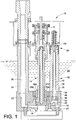
FIGURE 1 is a side cross-sectional view of a molten metal pump; -
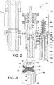
FIGURE 2 is a side cross-sectional view of an upper portion of the molten metal pump ofFIGURE 1 showing the connection between a support post and a motor mount; -
FIGURE 3 is a perspective view of a coupling unit and seat for the support post for the molten metal pump ofFIGURE 1 ; -
FIGURE 4 is a cross-sectional view of a portion of a molten metal pump showing a support post and coupling unit; -
FIGURE 5 is a cross-sectional view taken fromFIGURE 1 showing the connection between an impeller shaft and a motor for the molten metal pump ofFIGURE 1 ; -
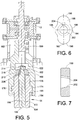
FIGURE 6 is a plan view of a shaft connector for the molten metal pump ofFIGURE I ; -
FIGURE 7 is a side cross-sectional view of the shaft connector shown inFIGURE 6 ; -
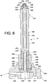
FIGURE 8 is a side cross-sectional view of an impeller and shaft assembly of the molten metal pump ofFIGURE 1 ; -
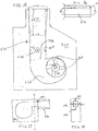
FIGURE 9 is a bottom plan view of the shaft assembly of the molten metal pump ofFIGURE I ; -
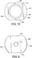
FIGURE 10 is a top plan view of a boot of the shaft assembly of the molten metal pump ofFIGURE 1 ; -
FIGURE 11 is a top perspective view of a cap member for use with an impeller of a molten metal pump, such as the pump depicted inFIGURE 1 ; -
FIGURE 12 is a bottom perspective view of the cap member ofFIGURE 11 ; -
FIGURE 13 is a perspective view of a gas tube plug for use with a gas injection molten metal pump; -
FIGURE 14 is a side perspective view of the gas injection tube in a pump outlet; -
FIGURE 15 is a schematic view of a pump base; -
FIGURE 16 is a schematic view representing the height dimension of a representative outlet; -
FIGURE 17 is a schematic view of a representative pump base wherein the outlet diffusing element forms a separate component secured to the base; -
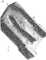
FIGURE 18 represents a cross section of the pump base ofFigure 17 ; -
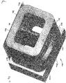
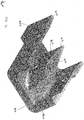
FIGURE 19 is a perspective view of the outlet diffusing element from an inlet end; -
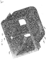
FIGURE 20 is a perspective view of the outlet diffusing element from an outlet end; -
FIGURE 21 is a perspective cross-sectional view of the outlet diffusing element; and -
FIGURE 22 is a perspective deep cross-sectional view of the inlet diffusing element. -
FIGURE 23 is a perspective view of an alternative gas tube plug; -
FIGURE 24 is a perspective view of a motor mount adjustment mechanism; -
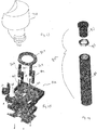
FIGURE 25 is an exploded perspective view of a motor mount including the adjustment mechanism ofFigure 24 ; and, -
FIGURE 26 is a side elevation view of a prior art molten metal gas injection pump; -
FIGURE 27 is a perspective view of an impeller base; and -
FIGURE 28 is a plan view of the impeller base ofFIGURE 27 . - The present invention provides an improved molten metal pump comprising the features of claim 1. The molten metal pump comprises an impeller, a pump base housing at least partially enclosing the impeller, a shaft connected to the impeller, a motor connected to the shaft, a motor mount plate for supporting the motor, a post for connecting the motor mount plate to the pump base housing, and a connector connecting the post to the motor mount plate, the connector comprising: a side wall, an internal wall extending from the side wall and including an axially aligned opening, the side wall and the internal wall defining a lower receptacle adapted to receive the post. The molten metal pump is characterized in that the side wall and the internal wall defining an upper receptacle adapted to cooperate with the motor mount plate or a structure connected to the motor mount plate. The molten metal pump can include a socket for connecting the shaft to the motor. The shaft can comprise an assembly including an elongated metal rod having a first end and a second end and a metal non-circular drive member attached at the second end of the elongated metal rod. The impeller can include a cap member having a plurality of inlet openings communicating with internal passages of the impeller, each inlet opening having an inner wall and an outer wall, the outer wall being longer than the inner wall, each inlet opening also including a leading wall and a trailing wall, the leading wall and the trailing wall each interconnecting the inner wall and the outer wall and each being inclined such that an uppermost edge of each wall precedes a lowermost edge of each wall in a first rotational direction.
- The molten metal pump can be used as a gas injection pump. A gas injection tube plug for use with the molten metal pump includes a body having a channel through which gas can flow and a ceramic tip member positioned within the body. A portion of the body is adapted to communicate with a gas injection source for providing gas to the channel. The ceramic tip member includes a passage in communication with the channel.
- The molten metal pump can include a fin disposed within the outlet passage. The fin includes a first tapered upstream portion and a second tapered downstream portion, these positions connected by a generally thicker portion wherein the walls of the outlet passage diverge at substantially the same degree of increase as the taper of the first end of the fin, and wherein a gas inject port extends through the fin, exiting the side walls thereof.
- The molten metal pump may have an inlet, an outlet, and a means for drawing molten metal into said inlet and expelling said molten metal from said outlet. The outlet comprises a channel having a first cross-sectional area at an upstream location and a second larger cross-sectional area at a terminal location. More particularly, the channel includes a length L, a height H, and a width W, wherein W generally increases according to an angle a greater than 0 from an upstream location Wu to a terminal location W1. Alternatively, or in addition thereto, the pump has a height H generally increasing according to an angle from an upstream location Hu to a terminal location Ht. Preferably, α lies between about 1.5 and 11 °, which β falls between about 1.0 and 10°. α and β can be comprised of an increasing dimension of one wall or the combination of an increasing dimension in opposed walls.
- A desired relationship between metal flow in the pump and the dimensions of the diffusing outlet may be provided. Q equals metal flow (in3/sec.) and Q/240 < (W, X H,)< Q/40. 0.026 < 1/2 (W, - WJ < 0.195, formula 0.017 < 1/2 (H, - HJL < 0.177.
- With reference to
FIGURE 1 , amolten metal pump 10 includes amotor 12 that drives animpeller shaft assembly 14 connected to animpeller 16. Thepump 10 moves molten metal by rotating theimpeller 16 located in apumping chamber 20 of apump base housing 18 to move molten metal through anoutlet passage 22 in the base housing towards ariser tube 24 having aninternal passage 26 through which the molten metal travels. Thebase housing 18 is positioned inside amolten metal bath 28.Post assemblies 32 space thebase housing 18 from amotor mount plate 34 upon which themotor 12 is mounted. - In
FIGURE 1 , the depictedpost assembly 32 includes a hollow cylindrical outerprotective sheath 36 having alongitudinal throughbore 38 that receives a cylindricalelongated rod 42. The outerprotective sheath 36 typically is made from a heat resistant and nonreactive material such as a refractory material including graphite, ceramic, and the like. Theelongated rod 42 is typically made from a material having a high tensile strength such as steel, but other suitable materials can also be used. - The
pump base housing 18 includes avertical bore 44 that is dimensioned to receive theelongated rod 42 of thepost assembly 32. Theelongated rod 42 extends through thevertical bore 44 into acavity 46. Therod 42 includes a threadedend 48 that cooperates with anut 52, or other retaining member, to retain the threadedend 48 of theelongated rod 42 inside and to thebase housing 18. Thenut 52 can have an inclined face that cooperates with an inclined wall in thepump base housing 16 that defines an upper wall of thecavity 46. Aligned with thevertical bore 44, thebase housing 18 also includes acircular recess 54 that is dimensioned to receive theouter sheath 36. Theouter sheath 36 and the retainingmember 52 inhibit molten metal from themolten metal bath 28 from contacting the metal elongatedrod 42. - Connection between the
post assembly 32 and themotor mount plate 34 is provided by acoupling unit 60. With reference toFIGURE 2 , thecoupling unit 60 includes an at least substantiallyannular wall 62 and aninternal wall 64 that extends from the annular wall in a plane that is normal to acentral axis 66 of thecoupling unit 60 and theelongated rod 42. Theannular wall 62 includesopenings 68 to allow for attachment of theinternal wall 64 to the annular wall. Theannular wall 62 and theinternal wall 64 can also be made as one integral piece, e.g. cast as one piece, which may obviate the need for theopenings 68. Theinternal wall 64 also includes acentral opening 70 aligned with thecentral axis 66. Theinternal wall 64 and theannular wall 62 define an upper cavity 72 (FIGURE 3 ) that is configured to cooperate with themotor mount plate 34 and/or a mounting structure, or seat, 74 that attaches to themotor mount plate 34 viafasteners 76. - As more clearly seen in
FIGURE 3 , theseat 74 includesfastener openings 78 dimensioned to receive the fasteners 76 (FIGURE 2 ) to attach theseat 74 to themotor mount plate 34. Theseat 74 can attach to themotor mount plate 34 in other conventional manners, for example welding. - The
seat 74 also includes acentral opening 82 that is dimensioned to receive theelongated rod 42. Thecentral opening 82 can have a polygonal configuration, which inFIGURE 3 is hexagonal, to accommodate a corresponding polygonal-shaped end 84 (FIGURE 2 ) of theelongated rod 42. Thecentral opening 82 and theend 84 of theelongated rod 42 can take other non-circular configurations. Thecentral opening 82 is aligned with thecentral axis 66. With reference back toFIGURE 2 , thepolygonal opening 82 limits rotation of the polygonal-shapedend 84 ofelongated rod 42 as a threadedfastener 86 is screwed into a threaded opening 88 in theend 84 to connect thepost assembly 32 to themotor mount plate 34. Alternatively, thecentral opening 70 of theinternal wall 64 can have a non-circular configuration and theopening 82 in theseat 74 can be circular. Theseat 74 also includes an externally threadedsidewall 90 that cooperates withinternal threads 92 formed in theupper cavity 72. The threaded connection between theseat 74 and thecoupling unit 60 allows for vertical adjustment of theentire post assembly 32. Theseat 74 also includes an uppercentral boss 94 that is received in a correspondingly shaped opening 96 (FIGURE 2 ) in themotor mount plate 34, both of which are aligned with thecentral axis 66. To attach theshaft assembly 32 to themotor mount plate 34, thecoupling unit 60 is screwed onto the mountingseat 74. Alternatively, the seat can be configured to receive theside wall 62. For example, the seat can be internally threaded and the side wall can be externally threaded. - In addition to the
upper cavity 72 described above, thecoupling unit 60 defines a lower cavity 98 (FIGURE 2 ) below theinternal wall 64 that is configured to receive theouter sheath 36 of thepost assembly 32. Theouter sheath 36 can include a tapered end that is received inside thelower cavity 98. Theouter sheath 36 and theelongated rod 42 are inserted into thelower cavity 98 of thecoupling unit 60 and the polygonal-shapedend 84 of theelongated rod 42 extends through thecentral opening 70 in theinternal wall 66 and into thecentral opening 82 in theseat 74. Thefastener 86 is inserted into the threaded central opening 88 in the polygonal-shapedend 84 of theelongated rod 42. Thefastener 86 extends through a biasingmember 104, for example Bellville springs having washers disposed at opposite ends, and is screwed into the threaded opening 88 of theelongated rod 42. The biasingmember 104 places therod 42 in tension which compresses theouter sheath 36. - The
coupling unit 60 provides for an easier connection between theshaft assembly 32 and themotor mount plate 34, as compared to known devices. The coupling between theshaft assembly 32 and themotor mount plate 34 has fewer parts than known coupling assemblies. Where a plurality of posts are provided in a molten metal pump, thecoupling unit 60 provides for a self leveling configuration by providing theseat 74 to which the coupling unit can adjustably connect. Also, the dimensions of theouter sheath 36 are not as critical as known devices because of the adjustable, e.g. threaded, connection between thecoupling unit 60 and theseat 74. - With reference to
FIGURE 4 , an alternative coupling arrangement between a graphite post and themotor mount plate 34 is disclosed. Acoupling unit 112 is similarly configured to thecoupling unit 60 disclosed inFIGURE 2 . Thecoupling unit 112 includes anannular wall 114 and aninternal wall 116 that is attached to theannular wall 114 and resides in a plane that is at least substantially normal to acentral axis 118 of thepost 110 and thecoupling unit 112. Theinternal wall 116 includes acentral opening 122 dimensioned to receive a fastener (not shown) similar to thefastener 86 depicted inFIGURE 2 . Theannular wall 114 and theinternal wall 116 define anupper cavity 124 that is configured to cooperate with themotor mount plane 34 and/or aseat 126. Theseat 126 can attach to themotor mount plate 34 in a similar manner as theseat 74 described inFIGURE 2 . The seat includes acentral opening 128 that is dimensioned to receive a fastener (not shown). Theseat 126 also includes apilot boss 132 that is received inside anopening 134 in themotor mount plate 34. Theannular wall 114 is threaded onto theseat 126 in a similar manner to that described inFIGURE 2 . - The
graphite post 110 includes ahorizontal bore 140 that extends through the post in a direction perpendicular to thecentral axis 118. Thebore 140 is configured to receive abarrel nut 142. Theannular wall 114 of thecoupling unit 112 includes alignedopenings 144 that are also configured for receipt of thebarrel nut 142. Thebarrel nut 142 includes a vertical threadedtap hole 146 that aligns with thecentral axis 118 when thebarrel nut 142 is properly positioned inside thebore 140. Thepost 110 also includes avertical bore 148 that is aligned with thecentral axis 118 and extends from an upper end of thepost 110 into thecross bore 140. - A fastener (not shown) similar to the
fastener 86 disclosed inFIGURE 2 , is inserted into thecentral opening 128 of theseat 126, thecentral opening 122 of theinternal wall 116, thevertical bore 148 of thepost 110 and the threadedtap hole 146 of thebarrel nut 140. Thefastener 86 can cooperate with a biasing member similar to that shown inFIGURE 2 . The fastener is tightened drawing thebarrel nut 140 upward which provides a compressive force on thepost 110 and can put the fastener in tension. Components from the coupling assembly described inFIGURE 4 can also be used with the coupling assembly described inFIGURES 2 and 3 . - With reference to
FIGURE 5 , the connection between themotor 12 and theimpeller shaft assembly 14 is disclosed. Adrive shaft 160 extends from themotor 12 and connects to asocket 162 that receives theimpeller shaft assembly 14. Theimpeller shaft assembly 14 includes a generally cylindrical hollowouter sleeve 164 that is made from a refractory material such as graphite, ceramic, or the like. Theouter sleeve 164 includes a verticalcentral throughbore 166 that is aligned with acentral axis 168 of theshaft assembly 14. Thecentral bore 166 receives anelongated rod 172 that is made from a heat resistant metal, such as a heat resistant steel that is known in the art. - The
outer sleeve 164 includes aradial shoulder 174 located near an upper end of the outer sleeve. Thesocket 162 includes a stepped cavity that defines alower cavity 176, acentral cavity 178, and anupper cavity 182. Thelower cavity 176 is appropriately dimensioned to receive theshoulder 174 of theouter sleeve 164. Thesocket 162 includesopenings 184 that receivepins 186 that are disposed just below theshoulder 174 of theouter sleeve 164 when theshaft assembly 14 is inserted into the socket's cavity. Thepins 186 can vertically retain theshaft assembly 14 inside thesocket 162. Thecentral cavity 178 is dimensioned to receive an upper portion of theouter sleeve 164 that is disposed above theshoulder 174. Theupper cavity 182 of thesocket 162 is appropriately dimensioned to matingly receive ashaft connector 188, which is described in more detail below. - With reference to
FIGURES 6 and 7 , theshaft connector 188 is made from a heat resistant steel. The periphery of theupper cavity 182 of the socket 162 (FIGURE 5 ), which is not circular, is shaped to match the periphery of theshaft connector 188. Thus when theshaft connector 188 is connected to the elongated rod 172 (FIGURE 5 ) and received inside the complementary shapedupper cavity 182 of thesocket 162, rotation of thesocket 162 results in rotation of theelongated rod 172. - As depicted in
FIGURES 6 and 7 , theshaft connector 188 is symmetrical in both a first, or major,axis 192 and a second, or minor,axis 194. Themajor axis 192 and theminor axis 194 are both perpendicular to one another and perpendicular to the central axis 168 (FIGURE 5 ). Theshaft connector 188 includes opposing circularlongitudinal ends 196 and opposinglateral sides 198 that interconnect the longitudinal ends 196. Theshaft connector 188 includes a keyedconical opening 202 that includes akeyway 204 extending into theshaft connector 188 from theconical opening 202. - With reference to
FIGURE 8 , theelongated rod 172 includes a conically taperedportion 206 that is received inside thecentral opening 202 of theshaft connector 188. The taperedportion 206 is shaped to matingly conform with thecentral opening 202 of theshaft connector 188. The taperedportion 206 includes akeyway 208 cut vertically into the outer surface of the taperedportion 206 that aligns with thekeyway 204 of theshaft connector 188. Thekeyways shaft connector 188 to theelongated rod 172. Theshaft connector 188 provides a metal-to-metal connector between thesocket 162 and theelongated rod 172 thus providing a strong connection between themotor shaft 160 and theimpeller shaft assembly 14. Anut 214 andwasher 216 can attach to an upper threadedend 218 of theelongated rod 172 to secure the key 212 vertically in place. Acotter pin 222 is received in a transverse throughbore adjacent the upper end of theelongated rod 172. - With reference to
FIGURE 8 , a lower end of theimpeller shaft assembly 14 attaches to theimpeller 16. Theimpeller 16 includes atop structure 240 that attaches to alower structure 242 using a key 244. Thetop structure 240 and thebottom structure 242 definevanes 246 through which the molten metal is pumped. Thebottom structure 242 also includes aninlet 248 where molten metal enters the impeller. Theimpeller 16 depicted is a bottom inlet impeller; however, the impeller can take other configurations, such as a top inlet impeller. - The
top structure 240 of theimpeller 16 includes an upwardly extendinghollow boss 252 that defines acavity 254 that receives the lower end of theshaft assembly 14. Anobround plate 256 attaches to a lower end of theelongated rod 172. As more clearly seen inFIGURE 9 , which is a bottom plan view of theshaft assembly 14, theplate 256 includes opposing roundedlongitudinal edges 258 and flattened lateral edges 262. Thecavity 254 of theimpeller 16 is appropriately shaped to match the periphery of thelower plate 256 so that rotation of theelongated rod 172 results in rotation of theimpeller 16. - With reference back to
FIGURE 8 , ahollow boot 270 having avertical throughbore 272 receives a lower end of theouter shield 164. Theouter shield 164 includes a taperedportion 274 that transitions into a lower portion that is received inside theboot 270. As more clearly seen inFIGURE 10 , which is a top plan view of theboot 270, the boot includes an annularupper portion 276 that extends upwardly from alower obround portion 278 that matches the configuration of thelower plate 256. Accordingly, theobround base 278 of theboot 270 includes roundedlongitudinal ends 286 and flattened lateral ends 288. Theboot 270 is made from a refractory material such as graphite, ceramic, or other similar material. With reference back toFIGURE 8 ,filler material 282 is interposed between a lower surface of thebase 278 of theboot 270 and an upper surface of thelower plate 256. Likewise, thefiller material 284 is interposed between theelongated rod 172 and theouter sleeve 164. The filler material can comprise granular graphite and other heat resistant materials. - The configuration of the
boot 270 provides a large bearing surface (i.e., flattened surfaces 288), to engage cooperating surfaces of thecavity 254 of theimpeller 16 so that theimpeller 16 can rotate along with theshaft assembly 14.Horizontal throughbores 290 are provided in theupper structure 240 of theimpeller 16 and align withhorizontal throughbores 292 in theboot 270. Cement can be injected through thebores boot 270 to theimpeller 16. - With reference back to
FIGURE 1 , theimpeller 16 is housed the pumpingchamber 20 defined in thepump base housing 18. Anannular bearing ring 294 having acentral bore 296 receives theboot 270. Thebearing ring 294 bears against astationary bearing ring 298 that is attached to thepump base housing 18. - With reference to
FIGURE 11 , acap member 300 for a top inlet impeller that can attach to theimpeller shaft assembly 14 is shown. Thecap member 300 can also attach at the bottom of an impeller to form a bottom inlet impeller. Vanes, similar to vanes 246 (FIGURE 8 ) are provided in both of the aforementioned impellers so that the impeller can move molten metal. Thecap member 300 disclosed inFIGURES 11 and12 increases the quantity of molten metal that can be pumped in a particular amount of time, as compared to known impellers. Themember 300 will be described as a cap member, however, it is understood that the member can attach to either the top or bottom of an impeller. - With reference again to
FIGURE 11 , thecap member 300 includes anupper surface 302 and a lower surface 304 (FIGURE 12 ). A plurality ofinlet openings 306 are formed through thecap member 300. Each inlet opening 306 will communicate with internal passages of an impeller, such aspassages 246 inFIGURE 8 . Thecap member 300 is meant to rotate in a clockwise direction as shown by arrow A. Each inlet opening 306 is defined by a leadingradial wall 308, a trailingradial wall 312, an innercircumferential wall 314, and an outercircumferential wall 316. The inner andouter walls walls circumferential walls 314 and the outercircumferential walls 316 can be generally concentric with a central rotational axis of theface 300. The intersection between adjacent walls results in rounded corners. - The leading
radial wall 308 and the trailingradial wall 312 are inclined as compared to the rotational axis of theface 300 such that molten metal travels downward along the planar leading and trailing walls into the impeller. In other words, an uppermost edge of eachleading wall 308 and each trailingwall 312 precedes a lowermost edge of eachleading wall 308 and each trailingwall 312 as the impeller rotates in the clockwise direction. The angle of inclination is about to about degrees for each of the walls. The walls can be parallel to one another; however, the walls can be situated other than parallel to one another. The inclined walls encourage more molten metal to enter the impeller passages as compared to vertically oriented inlet walls. Furthermore, the generally concentricinner wall 314 andouter wall 316 provide a larger inlet opening as compared to circular inlet or rectangular inlet openings in that only inclined bar-like spokes 318 that are defined by theinlet openings 306 interrupt the flow of molten metal into the impeller. Even where theinner wall 314 and theouter wall 316 are linear, the opening has a generally trapezoidal shape to provide a larger opening. Accordingly, more inlet opening surface area is provided to receive more molten metal. - The
cap member 300 includes acentral opening 322 to accommodate an impeller shaft, such as theimpeller shaft assembly 14 ofFIGURE 1 . Even though the central opening is depicted as circular, it can be shaped to accommodate a non- circular portion of theimpeller shaft assembly 14. As depicted inFIGURES 11 and12 , thecap member 300 also includes aperipheral wall 324 that depends away from thelower surface 304 of the cap member. Theperipheral wall 324 can attach to a lower portion of an impeller, such as thebottom structure 242 depicted inFIGURE 1 . - The molten metal pump depicted in
FIGURE 1 is referred to as a transfer pump since molten metal is transferred to another location through thepassage 26 in theriser tube 24. The molten metal pump can be used in other environments as a gas injection pump where theoutlet 22 and the base 18 would be substantially horizontally disposed to communicate with adischarge device 330 depicted inFIGURE 14 . - The
cap member 300 can also attach to abase member 900, which is depicted inFIGURES 27 and 28 . Thebase member 900 includes acentral opening 902 formed in a raisedcentral boss 904. Thecentral opening 902 aligns with thecentral opening 322 of thecap member 300 to accommodate the impeller shaft assembly 14 (FIGURE 1 ). A plurality ofradial walls 906, or impeller blades, extend radially from thecentral boss 904. Eachradial wall 906 includes anotch 908 formed in an upper outer end of the radial wall. Thenotch 908 accommodates theperipheral wall 324 of the cap member 300 (FIGURE 12 ). - Each
radial wall 906 includes afirst surface 912 and asecond surface 914. When thebase member 900 rotates in a clockwise direction, thefirst surface 912 can be referred to as a leading surface and thesecond surface 914 can be referred to as a trailing surface. When thebase member 900 rotates in a counterclockwise direction, thefirst surface 912 can be referred to as a trailing surface and thesecond surface 914 can be referred to as a leading surface. The first and second surfaces define anoutlet passage 916, which is generally horizontal. - Each
radial wall 906 includes a chamferedperipheral end 918 that extends towards into theoutlet passage 916. Accordingly, thefirst surface 912 is angled at its peripheral edge toward thesecond surface 914 of an adjacentradial wall 906 that defines theoutlet passage 916 defined by the subject first surface and the subject second surface. The chamferedperipheral end 918 acts as a sort of exit inducer and can further increase the velocity of the molten metal that passes through the impeller. - The
cap member 300 attaches to thebase member 900 such that thespokes 318 of the cap member align with theradial walls 906 of the base member. Thecap member 300 can be cemented to thebase member 900. The entire impeller can have a height of about seven inches, which is less than known impellers. If desired, a bearing ring (not shown inFIGURES 27 and 28 ) can attach to a lower portion of thebase member 900. - For a gas injection pump, molten metal is pumped through an
outlet passage 332 formed in thedischarge device 330 that is in communication with the pumping chamber 20 (FIGURE 1 ). Gas such as chlorine is introduced into thedischarge passage 332 through apassage 334 formed in agas injection tube 336. Atube plug 338 mounts to thedischarge device 330 inside anopening 342. The tube plug includes acontoured opening 344 that receives a lower end of thegas discharge tube 336 to allow communication between thepassage 334 in thegas discharge tube 336 and thedischarge outlet passage 332. - In known devices that pump molten aluminum, magnesium chloride tends to buildup near the location where the chlorine is introduced in the discharge stream, e.g. the molten metal stream passing through the
discharge passage 332. The buildup of magnesium chloride can result in great difficulty in removing the discharge tube from the tube plug. A great enough flow of molten metal through thedischarge passage 332 results in a vacuum being created where the chlorine is introduced into the discharge stream. Accordingly, the buildup of magnesium chloride can be greatly reduced or eliminated. By using the cap member 300 (FIGURES 11 and12 ) on an impeller of a pump, the flow through thedischarge passage 332 can be greatly increased, as compared to known impellers operating at the same RPM. - Where great enough flow is achieved, the
gas injection tube 334 can be received inside theopening 344 formed in thetube plug 338 without the need of cement to secure thetube 336 to theplug 338. Thegas injection tube 336 includes atapered end 358 that has a complementary shape to the conically shapedopening 344 in theplug 338. Theplug 338 includes aslanted opening 366. A ceramic tube is received inside and extends from theopening 366. - The
tube plug 338 includes a generally elliptically shapedintermediate portion 372 extending from acylindrical portion 362. Theintermediate portion 372 transitions into adistal fin 374 having a taperededge 376. The elliptically shapedportion 372 andfin 374 can extend into the discharge opening 332 of thegas discharge device 330. The flow of molten metal can be in the direction from the vertical end of thefin 374 towards thetapered edge 376, or vice versa, which is shown inFIGURE 14 . Theceramic tip member 368 can extend into the molten metal stream flowing through thedischarge opening 332. The depth that theceramic tip member 368 extends into the molten stream can vary from the top of the molten metal stream to near the bottom of the molten metal stream. In one alternative design, it is feasible that theentire fin element 374 or even theentire tube plug 338 be comprised of ceramic. - Having the
ceramic tip 368 extend into the molten metal stream extends the life of the system, as compared to known systems that use only graphite to make the components of the gas injection system. Theceramic tip 368 can extend into the molten metal stream so that gas that is injected into the stream is injected at a lower portion of the stream. - In contrast to known gas injection systems, the
gas injection tube 336 can be seated in theopening 344 of thetube plug 338 without cementing the tube to the plug, where the flow of molten metal through thedischarge outlet 332 is such that an adequate vacuum is created. The shape of thefin 374 and the intermediateelliptical region 372 is such that the flow of molten metal is not greatly hindered. The shape of the discharge passage can also be made to minimize the flow- hindering effect of the tube plug 364, for example by widening the discharge passage in the area that is adjacent thetube plug 338. - Referring now to
FIG. 26 , a typical gas injection pump 400 is depicted. Particularly, the pump 400 includes ahanger assembly 402 used for lifting and positioning of the pump as necessary within a furnace (not shown). A motor 403 is supported by a motor mount 404, itself supported by a support plate 406. The motor 403 is connected via a coupling assembly 408 to a rotatable shaft 410 secured to an impeller 412. - A base assembly 414 rests on the floor of a refractory furnace and forms a foundation for the support plate 406 and motor mount 404 by a plurality of posts 416. The impeller 412 is rotatable within a pumping chamber 418 and its rotation draws molten metal 419 into the pumping chamber 418 through an inlet 420 and discharges the molten metal through an outlet passage 422.
- A reactive gas is provided to a gas injection tube 424 supported by a clamping mechanism 426 attached to the support plate 406. The submerged end of the gas injection tube 424 is connected via a tube plug 428 to the outlet passage 422. Adjacent the discharge opening 430 of the outlet passage 422 is a convergent nozzle 425. Particularly, the outlet "necks down" to form an area of restriction 432 (a "zone of convergence") injection point. Unfortunately, this design increases velocity of the metal at the outlet and restricts flow resulting in increased impact with the relatively stationary molten metal in the charge well.
- In contrast to this design, there is included a divergent fan type of outlet. Otherwise, the pumps can be similar.
- Referring now to
Figure 15 , a centrifugal moltenmetal pump base 560 is depicted. Withinbase 560, avolute pumping chamber 562 which houses animpeller 564 is provided. Upon rotation ofimpeller 564, molten metal enters the impeller inlet 566 through thepump base 560 inlet (not shown) and exits intovolute chamber 562 viamultiple passages 568. Accordingly, molten metal is forcibly expelled from thevolute chamber 562 intooutlet passage 570.Outlet passage 570 includes agas injection inlet 572 and a fan diffusing section 574. Preferably, thegas injection inlet 572 is positioned downstream ofline 576 which is positioned generally perpendicular to the volute cut water and upstream of the fan diffusing section 574. Thepump impeller 564 has a radial wall which lies generally tangential to an imaginary line extended from the near wall 578 of theoutlet passage 570. - Fan diffusing section 574 can be characterized by an upstream width (WJ and a terminal width (WT). WT exceeds that of Wu as a result of the diverging nature of the side walls in the width direction. In this instance, the increase in width is shown by an increasing dimension of the angle α of each wall. However, the increase does not necessarily occur in each wall but could be expressed in a single wall. This arrangement is shown particularly in
Figure 16 wherein the height aspect of fan diffusing section 574 is depicted. More particularly, fan diffusing section 574 increases in its height according to angle β providing a greater terminal height dimension H1- than an upstream height dimension H1J. - Referring now to
Figure 17 , the design is shown in an alternative form, wherein thefan diffusing section 580 comprises a separate component from base 582.Fan diffusing section 580 can be attached to base 582 by any means available to the skilled artisan, including a dowel/cement combination 584, a threaded connection, cement alone, or any other suitable technique. - Referring now to
Figure 18 , the use of an alternative gas injection system is depicted whereingas injection inlets 590 are dispersed to each wall of the outlet passage 592. Thegas injection inlet 590 can feed via separate gas lines or via a single gas line in combination with a splitting mechanism. In any event, this design is believed to aid gas dispersion. - Thereby, the outlet flow pressure pulsations resulting in a similar reduction in pump base fractures are reduced. Furthermore, it has been determined that an increase in molten metal penetration into the charge well is established. As a skilled artisan will recognize, the primary significance of utilizing a molten metal pump for circulation is to provide the desired BTU units in the form of molten metal from the furnace to the charge well. If molten metal penetration into the charge well is too low, insufficient energy is provided for the melting of scrap charge therein. If molten metal velocity into the charge well is too high, undesirable disruption of the charge well molten metal surface results in undesirable oxidation. More particularly, the pump metal would diffuse outwardly at an angle equal to 2α increasing the charge wells swept area. In short, the introduced metal wets a more significant area of the charge well.
- In addition, by increasing the molten metal outlet pressure, deeper and smoother penetration into the stationary metal pool of the charge well results. Historically, the introduction of a high velocity metal flow from the outlet to a stationary charge well pool results in significant impact vibration often causing cracking of the molten metal pump components, particularly the base. By reducing the flow velocity and increasing flow pressure utilizing the fan diffusing outlet, impact vibrations are reduced. Advantageously, this also allows the pump to operate at higher rotational speeds and/or tangential velocities.
- It should be noted that the depicted pump is a gas injection type but that any type of circulation or electromagnetic pump and in fact, any type of pump transporting molten metal may benefit by the inclusion of the present fan diffusing outlet design.
- Referring again to
Figure 15 , the gas injection inlet is positioned in the base slightly downstream of theline 576 and slightly upstream of the fan diffusing outlet section 574. The upstream location of the gas injection inlet is limited by the desire to prevent gas from being circulated into thevolute pumping chamber 562. The gas injection upstream of the fan diffuser element is to allow gas introduction at a relatively lower pressure location. Of course, the gas injection orifices could be multiple and located anywhere including top, sides or bottom of the outlet, as long as they are concentric or if multiple injection is used, it is symmetrical to the outlet access. Advantageously, introduction of the gas in this location with the downstream fan diffusing section high pressure zone reduces the tendency for bubbles to coalesce into a larger pocket which is more difficult to keep entrained in the molten metal. - In general, there is provided a longer gas residence, slower bubble coalescence formation, high gas dispersion into the metal proportional to peripheral velocity and metal flow, deeper gas penetration into the stationary metal, no gas backflow out of the pump inlet, higher metal flows at similar gas flows of prior designs, no pump flow velocity reduction, no outlet flow pressure fluctuations resulting from large velocity changes and limited vibration and material fatigue due to high resonance stress and hydraulic waves.
- Referring now to
Figures 19-22 , a gas injection adapter is depicted. Importantly, while the adapter 600 is depicted herein as a component separate from the molten metal base, it is to be noted that the adapter can be constructed as an integral component of the material forming the base as well. - Adapter 600 is comprised of a graphite, ceramic or other molten metal
resistant body 601 having aninlet end 602, and anoutlet end 604. Thebody 601 defines apassage 606 within which bifurcatingfin 608 is positioned. The fin 108 is depicted as aligned along a longitudinal axis L of the adapter 600; however, the fin can be located elsewhere or could be curved if desired. Bifurcatingfin 608 includes a tapered leading edge 610, preferably having an angular increase of between about 5 degrees and 15 degrees with respect to a longitudinal axis L of the adapter 100, and atapered trailing edge 612, preferably having an angular decrease of between about 2 degrees and 8 degrees with respect to the longitudinal axis of the adapter. Tapered leadingedge 608 and tapered trailing edge 610 are joined by a central section 614 having two generally planar side walls 616 that are parallel to one another. The leading edge 610 of thefin 608 is shorter, thus having a larger increasing angle, as compared to the longer trailingedge 612. - Internal walls of
passage 606 are formed such that their dimensions substantially mirror that of the leading and trailing edges and central region offin 608. Moreover, the walls ofpassage 606 will be relieved in these areas consistent with the area of passage eliminated by thefin 608. Such a configuration mitigates the impact on the flow of molten metal through the adapter by providing a constant or increasing flow area (an area taken at a cross-section perpendicular to the longitudinal axis L) throughout the adapter. Accordingly, interior walls 618 in region 620 increase at an angular rate of between about 5 degrees and 15 degrees generally matching the outer dimension of leading edge 610. Interior walls 621 adjacent the central region 622 can be relatively flat. Interior walls 624 adjacent to the rear region 626 can remain flat or in fact, continue to diverge to provide the apparatus with the benefits of the diffusing fan discussed above. In this manner, turbulence is not introduced into the molten metal stream to an influential level. - Outlet adapter 600 includes a recessed gas injection
tube receiving region 628 having chamferededges 629 to facilitate the seating of a gas injection tube (not shown).Seat 628 includes at least onegas injection port 630 that extends intofin 608 and including two outlet ports 632, providing gas access to molten metal flowing passedfin 608. Of course, many outlet port locations are feasible. For example, the ports can be moved forwardly-rearwardly and higher-lower than shown. Similarly, the angle at which the part is directed into the molten metal stream is adjustable. Therefore, the fin design allows the gas to be injected at a maximum suction point. The greater the suction, the more gas that can be injected and metal treated. Adapter 600 includes side wall holes 634, provided to facilitate the machining of the ports 632. - The bifurcated pump outlet advantageously allows gas injected to be at the load center for maximum residence, maximum flow velocity, and maximum stream penetration. One significant advantage is no volute area constriction is created. In addition, gradual volute discharge area expansion exists to minimize bubble coalescence. Similarly, dual metal flow coalescence occurs for maximum gas retention occurs with no velocity turbulence.
- In addition, by design selection of the taper of the side walls at the downstream point, the exist velocity is allowing metal to metal penetration velocity between 4 to 20 ft/sec.
- Referring now to
Figure 23 , an alternativegas injection tube 700 is shown. As opposed to a single or double gas inlet port (ex.Figures 13- 14, and 19-22 ) a plurality ofoutlet ports 703. Preferably, each individual port will have an opening dimension no greater than 5% of the overall gas discharge outlet area. - Referring now to
Figures 24 and 25 , an alternative leveling mechanism is depicted. More particularly, amotor mount assembly 800 is shown including among other elements, a primary support plate 803 to which the pump posts can be secured. Four threadedstud elements 805 are secured to the plate 803. Mountingring 807 is positioned onstud elements 805 and the motor (not shown) secured thereto. Intermediate plate 803 and mountingring 807, and positioned onstuds 805, areadjustment elements 809.Adjustment elements 809 are constructed of tube element 811 , threadedadjustment cap 813 and locking ring 815.Adjustment cap 813 includes a threaded outer surface 817 suitable for mating with locking ring 815. The internal bore of lockingcap 813 is threaded to mate withstuds 805. The design depicted herein facilitates the adjustment ofmotor ring 807 and hence a motor mounted thereon. Advantageously, a slight adjustment ofelements 809 facilitates the proper orientation of the shaft and impeller elements described hereinabove. - A molten metal pump and the components that make up the molten metal pump have been described above in sufficient detail so that one skilled in the art can make and use the device. Directional terms such as "upper," "lower," "vertical," "horizontal" and the like have been used to describe the figures and are not used to limit the location of certain components. A number of alternatives of the above-described examples may occur to those skilled in the art upon reading the preceding description, which fall within the scope of the invention as defined by the appended claims.
Claims (21)
- A molten metal pump (10) comprising:an impeller (16);a pump base housing (18) at least partially enclosing the impeller (16);a shaft (14) connected to the impeller (16);a motor (12) connected to the shaft (14);a motor mount plate (34) for supporting the motor (12);a post (32) for connecting the motor mount plate (34) to the pump base housing (18),and a connector (60) connecting the post (32) to the motor mount plate (34);the connector (60) comprising:a side wall (62);an internal wall (64) extending from the side wall (62) and including an axially aligned opening (70), the side wall (62) and the internal wall (64) defining a lower receptacle (98) adapted to receive the post (32),characterized in that
the side wall (62) and the internal wall (64) defining an upper receptacle adapted to cooperate with a motor mount plate or a structure (74) connected to the motor mount plate (34). - The pump of claim 1, wherein the opening (70) in the internal wall (64) is adapted to receive an elongated rod (42) that is a component of the post assembly (14).
- The pump of claim 1 or 2, further comprising a mounting structure (74) adapted to be connected to the motor mount (34) of the associated molten metal pump and be received inside the upper receptacle (72).
- The pump of claim 3, wherein the mounting structure (74) includes external threads (90) and the side wall (62) includes internal threads (92), in the upper receptacle (72).
- The pump of claim 3, wherein the mounting structure (74) includes an opening (82) aligned with the opening (70) in the internal wall (64), wherein at least one of the openings has a non-circular periphery.
- The pump of one of the preceding claims, wherein the side wall (62) includes openings (68) adjacent the internal wall (64).
- The pump of one of the preceding claims, wherein the side wall (62) includes at least one opening spaced from the internal wall and leading to the lower receptacle (98).
- The pump of claim 7, further comprising a barrel nut (142) dimensioned to be received in the at least one opening (140), the barrel nut including a threaded opening (146) that is adapted to align with the opening in the internal wall (116).
- The pump of claim 1, further comprising a device for providing an adjustable connection between the post (32) and the motor mount plate (34) comprising:a side wall (62) defining a receptacle (98) dimensioned to receive a post (32) for an associated molten metal pump; andan upper portion (72) that is adapted to adjustably mount to a motor mount or a structure that is connected to the motor mount of the associated molten metal pump (10) to allow for adjustment of the of the device in an axis defined by the longitudinal axis of the post for the associated molten metal pump.
- The pump of claim 9, wherein the upper portion (72) of the device is threaded.
- The pump of one of the preceding claims, further comprising a device for connecting an impeller shaft (14) to a motor (12), the device comprising:a socket (162) adapted to connect to a drive shaft (160) of a motor (12) of an associated molten metal pump, the socket including a stepped cavity defining an upper cavity (182) and a lower cavity (176), the upper cavity having a non-circular configuration in a cross section taken normal to a central axis of the socket, and the lower cavity being adapted to receive an impeller shaft assembly (14) of the associated molten metal pump.
- The pump of claim 11, further comprising a shaft connector (188) having
a central opening (202) for receiving an elongated rod (172) of the impeller shaft assembly and a periphery shaped so that the shaft pump is matingly received by the upper cavity (182) so that rotation of the socket (162) results in rotation of the shaft pump. - The device of claims 11 or 12, further comprising a key for locking the shaft connector (188) to the elongated rod (172).
- The pump of one of the preceding claims, wherein the impeller (16) comprises:a generally cylindrically shaped body having a rotational axis; anda cap member (300) attached to the body and having a plurality of inlet openings (306) communicating with internal passages of the body, each inlet opening having an inner wall (314) and an outer wall (316), the outer wall being longer than the inner wall, each inlet opening also including a leading wall and a trailing wall, the leading wall (308) and the trailing wall (312) each interconnecting the inner wall and the outer wall and each being inclined such that an uppermost edge of each wall precedes a lower-most edge of each wall in a first rotational direction.
- The pump of claim 14, wherein the inlet openings (306) define one of a plurality of radial bar-like spokes, curved spokes, or radial offset spokes.
- The pump of claims 14 or 15, wherein the inner wall (314) of each inlet opening (306) is generally parallel to the outer wall (316).
- The pump of claim 14, 15 or 16, wherein the leading wall (308) and the trailing wall (312) are planar or concave.
- The pump of one of the preceding claims including a gas injection tube plug (338) comprising:a body having a channel through which gas can flow, a portion of the body being adapted to communicate with a gas injection source for providing gas to the channel; anda ceramic tip member (368) disposed within the body, the ceramic tip member including a passage in communication with the channel.
- The pump of claim, 18, wherein the body comprises a fin-shaped portion (274) adapted to be disposed in a stream of molten metal, wherein the ceramic tip member (368) extends from the fin-shaped portion.
- The pump of claim 18, wherein the shape of the outlet passage (332) is such that the outlet passage widens in an area that receives the fin-shaped portion.
- The pump of one of the preceding claims including an outlet adapter (600) comprising a body forming a passage wherein a fin (608) is disposed within said outlet passage, said fin having a first tapered upstream and a second tapered downstream end connected by generally thicker region wherein the walls of said outlet passage diverge at substantially the same degree of increase as the taper of the first end of said fin, and wherein a gas inject port extends through said fin, exiting at least one side wall thereof.
Priority Applications (1)
| Application Number | Priority Date | Filing Date | Title |
|---|---|---|---|
| EP16207575.8A EP3181916B1 (en) | 2004-07-07 | 2005-07-07 | Molten metal pump |
Applications Claiming Priority (4)
| Application Number | Priority Date | Filing Date | Title |
|---|---|---|---|
| US58613404P | 2004-07-07 | 2004-07-07 | |
| US60764404P | 2004-09-07 | 2004-09-07 | |
| US67582805P | 2005-04-28 | 2005-04-28 | |
| PCT/US2005/024044 WO2006014517A2 (en) | 2004-07-07 | 2005-07-07 | Molten metal pump |
Related Child Applications (1)
| Application Number | Title | Priority Date | Filing Date |
|---|---|---|---|
| EP16207575.8A Division EP3181916B1 (en) | 2004-07-07 | 2005-07-07 | Molten metal pump |
Publications (3)
| Publication Number | Publication Date |
|---|---|
| EP1778986A2 EP1778986A2 (en) | 2007-05-02 |
| EP1778986A4 EP1778986A4 (en) | 2011-03-16 |
| EP1778986B1 true EP1778986B1 (en) | 2017-01-04 |
Family
ID=35787635
Family Applications (2)
| Application Number | Title | Priority Date | Filing Date |
|---|---|---|---|
| EP05769567.8A Active EP1778986B1 (en) | 2004-07-07 | 2005-07-07 | Molten metal pump |
| EP16207575.8A Active EP3181916B1 (en) | 2004-07-07 | 2005-07-07 | Molten metal pump |
Family Applications After (1)
| Application Number | Title | Priority Date | Filing Date |
|---|---|---|---|
| EP16207575.8A Active EP3181916B1 (en) | 2004-07-07 | 2005-07-07 | Molten metal pump |
Country Status (8)
| Country | Link |
|---|---|
| US (2) | US9951777B2 (en) |
| EP (2) | EP1778986B1 (en) |
| JP (4) | JP4874243B2 (en) |
| CA (3) | CA2948335C (en) |
| ES (2) | ES2857580T3 (en) |
| MX (1) | MX348717B (en) |
| PL (1) | PL1778986T3 (en) |
| WO (1) | WO2006014517A2 (en) |
Families Citing this family (31)
| Publication number | Priority date | Publication date | Assignee | Title |
|---|---|---|---|---|
| US20070253807A1 (en) | 2006-04-28 | 2007-11-01 | Cooper Paul V | Gas-transfer foot |
| US9410744B2 (en) | 2010-05-12 | 2016-08-09 | Molten Metal Equipment Innovations, Llc | Vessel transfer insert and system |
| US9156087B2 (en) | 2007-06-21 | 2015-10-13 | Molten Metal Equipment Innovations, Llc | Molten metal transfer system and rotor |
| US8366993B2 (en) | 2007-06-21 | 2013-02-05 | Cooper Paul V | System and method for degassing molten metal |
| US9409232B2 (en) | 2007-06-21 | 2016-08-09 | Molten Metal Equipment Innovations, Llc | Molten metal transfer vessel and method of construction |
| US8337746B2 (en) | 2007-06-21 | 2012-12-25 | Cooper Paul V | Transferring molten metal from one structure to another |
| US9205490B2 (en) | 2007-06-21 | 2015-12-08 | Molten Metal Equipment Innovations, Llc | Transfer well system and method for making same |
| US9643247B2 (en) | 2007-06-21 | 2017-05-09 | Molten Metal Equipment Innovations, Llc | Molten metal transfer and degassing system |
| US8444911B2 (en) | 2009-08-07 | 2013-05-21 | Paul V. Cooper | Shaft and post tensioning device |
| US8524146B2 (en) | 2009-08-07 | 2013-09-03 | Paul V. Cooper | Rotary degassers and components therefor |
| US8535603B2 (en) | 2009-08-07 | 2013-09-17 | Paul V. Cooper | Rotary degasser and rotor therefor |
| US10428821B2 (en) | 2009-08-07 | 2019-10-01 | Molten Metal Equipment Innovations, Llc | Quick submergence molten metal pump |
| US9108244B2 (en) | 2009-09-09 | 2015-08-18 | Paul V. Cooper | Immersion heater for molten metal |
| JP2014512480A (en) * | 2011-04-18 | 2014-05-22 | パイロテック インコーポレイテッド | Mold pump assembly |
| DE102011051961A1 (en) * | 2011-07-20 | 2013-01-24 | Zf Lenksysteme Gmbh | Device for securing a unit |
| PL220603B1 (en) | 2012-03-31 | 2015-11-30 | Biopal Spółka Z Ograniczoną Odpowiedzialnością | Liquid metal pump for the chemical reactor heating circuit |
| US9903383B2 (en) | 2013-03-13 | 2018-02-27 | Molten Metal Equipment Innovations, Llc | Molten metal rotor with hardened top |
| US9011761B2 (en) | 2013-03-14 | 2015-04-21 | Paul V. Cooper | Ladle with transfer conduit |
| US10052688B2 (en) | 2013-03-15 | 2018-08-21 | Molten Metal Equipment Innovations, Llc | Transfer pump launder system |
| KR101307447B1 (en) * | 2013-04-10 | 2013-09-11 | 김형용 | Supply pump for molten metals |
| US20140363309A1 (en) * | 2013-06-07 | 2014-12-11 | Pyrotek, Inc, | Emergency molten metal pump out |
| US10138892B2 (en) | 2014-07-02 | 2018-11-27 | Molten Metal Equipment Innovations, Llc | Rotor and rotor shaft for molten metal |
| RU2589735C2 (en) * | 2014-11-19 | 2016-07-10 | Открытое Акционерное Общество "Акмэ-Инжиниринг" | Pump for transfer of molten metal |
| US10947980B2 (en) | 2015-02-02 | 2021-03-16 | Molten Metal Equipment Innovations, Llc | Molten metal rotor with hardened blade tips |
| US10267314B2 (en) | 2016-01-13 | 2019-04-23 | Molten Metal Equipment Innovations, Llc | Tensioned support shaft and other molten metal devices |
| CN109642581B (en) * | 2016-07-25 | 2022-07-12 | 派瑞泰克有限公司 | Open outlet type molten metal gas injection pump |
| WO2019018733A1 (en) | 2017-07-20 | 2019-01-24 | Pyrotek, Inc. | Mold pump engagement apparatus |
| US11149747B2 (en) | 2017-11-17 | 2021-10-19 | Molten Metal Equipment Innovations, Llc | Tensioned support post and other molten metal devices |
| US11858036B2 (en) | 2019-05-17 | 2024-01-02 | Molten Metal Equipment Innovations, Llc | System and method to feed mold with molten metal |
| CN117715716A (en) * | 2021-04-23 | 2024-03-15 | 派瑞泰克有限公司 | Shaft and column assembly for molten metal apparatus |
| US11873845B2 (en) | 2021-05-28 | 2024-01-16 | Molten Metal Equipment Innovations, Llc | Molten metal transfer device |
Family Cites Families (47)
| Publication number | Priority date | Publication date | Assignee | Title |
|---|---|---|---|---|
| FR2182623B1 (en) * | 1972-03-30 | 1974-12-20 | Activite Atom Avance | |
| US4052199A (en) | 1975-07-21 | 1977-10-04 | The Carborundum Company | Gas injection method |
| FR2358576A1 (en) * | 1976-07-12 | 1978-02-10 | Robot Coupe Sa | DEVICE FOR FIXING TOOLS ON THE AXLE OF A MOTOR, ESPECIALLY FOR APPLIANCES |
| US4169584A (en) | 1977-07-18 | 1979-10-02 | The Carborundum Company | Gas injection apparatus |
| JPS63120897A (en) * | 1986-11-10 | 1988-05-25 | Matsuda Pump Seisakusho:Kk | Ceramic pump for melted metal |
| EP0286809B1 (en) * | 1987-04-10 | 1991-10-16 | Rockwell International Corporation | Cavitation-resistant inducer |
| US5092821A (en) * | 1990-01-18 | 1992-03-03 | The Carborundum Company | Drive system for impeller shafts |
| JPH03164594A (en) * | 1990-10-30 | 1991-07-16 | Matsuda Pump Seisakusho:Kk | Molten metal pump made of ceramic |
| CA2097648C (en) * | 1992-06-12 | 1998-04-28 | Ronald E. Gilbert | Molton metal pump with vaned impeller and flow directing pumping chamber |
| DE4221705A1 (en) * | 1992-07-02 | 1994-01-05 | Voith Gmbh J M | Hydrostatic machine with axial thrust compensation |
| US5662725A (en) | 1995-05-12 | 1997-09-02 | Cooper; Paul V. | System and device for removing impurities from molten metal |
| US5685701A (en) * | 1995-06-01 | 1997-11-11 | Metaullics Systems Co., L.P. | Bearing arrangement for molten aluminum pumps |
| US5735668A (en) * | 1996-03-04 | 1998-04-07 | Ansimag Inc. | Axial bearing having independent pads for a centrifugal pump |
| US5785494A (en) * | 1996-04-23 | 1998-07-28 | Metaullics Systems Co., L.P. | Molten metal impeller |
| US5993728A (en) | 1996-07-26 | 1999-11-30 | Metaullics Systems Co., L.P. | Gas injection pump |
| US6254340B1 (en) | 1997-04-23 | 2001-07-03 | Metaullics Systems Co., L.P. | Molten metal impeller |
| US6019576A (en) * | 1997-09-22 | 2000-02-01 | Thut; Bruno H. | Pumps for pumping molten metal with a stirring action |
| US6071074A (en) | 1998-08-07 | 2000-06-06 | Alphatech, Inc. | Advanced motor driven impeller pump for moving metal in a bath of molten metal |
| US6093000A (en) * | 1998-08-11 | 2000-07-25 | Cooper; Paul V | Molten metal pump with monolithic rotor |
| US6887425B2 (en) * | 1998-11-09 | 2005-05-03 | Metaullics Systems Co., L.P. | Shaft and post assemblies for molten metal apparatus |
| AU760328B2 (en) | 1998-11-09 | 2003-05-15 | Metaullics Systems Co., L.P. | Shaft and post assemblies for molten metal pumping apparatus |
| JP4081889B2 (en) * | 1998-11-11 | 2008-04-30 | 日産自動車株式会社 | High-voltage harness wiring structure for electric vehicles |
| JP3891533B2 (en) * | 1998-11-16 | 2007-03-14 | アイシン・エィ・ダブリュ株式会社 | Drive device |
| US6303074B1 (en) * | 1999-05-14 | 2001-10-16 | Paul V. Cooper | Mixed flow rotor for molten metal pumping device |
| US6457940B1 (en) * | 1999-07-23 | 2002-10-01 | Dale T. Lehman | Molten metal pump |
| US6439860B1 (en) | 1999-11-22 | 2002-08-27 | Karl Greer | Chambered vane impeller molten metal pump |
| US6562286B1 (en) | 2000-03-13 | 2003-05-13 | Dale T. Lehman | Post mounting system and method for molten metal pump |
| US6524006B1 (en) | 2000-04-11 | 2003-02-25 | International Business Machines Corporation | Fluid dynamic bearing assembly |
| JP3843702B2 (en) * | 2000-06-09 | 2006-11-08 | アイシン・エィ・ダブリュ株式会社 | Driving device for driving electric vehicle |
| US6524066B2 (en) * | 2001-01-31 | 2003-02-25 | Bruno H. Thut | Impeller for molten metal pump with reduced clogging |
| US6533535B2 (en) * | 2001-04-06 | 2003-03-18 | Bruno H. Thut | Molten metal pump with protected inlet |
| JP4159797B2 (en) * | 2001-05-10 | 2008-10-01 | 株式会社ミツバ | Electric motor |
| US6709234B2 (en) * | 2001-08-31 | 2004-03-23 | Pyrotek, Inc. | Impeller shaft assembly system |
| JP3988725B2 (en) * | 2002-04-04 | 2007-10-10 | 株式会社日立製作所 | Power conversion apparatus, power system including the same, and moving body |
| JP2003311398A (en) * | 2002-04-16 | 2003-11-05 | Nihon Dennetsu Keiki Co Ltd | Induction type electromagnetic pump for lead-free solder |
| US7402276B2 (en) * | 2003-07-14 | 2008-07-22 | Cooper Paul V | Pump with rotating inlet |
| JP4014152B2 (en) * | 2002-10-09 | 2007-11-28 | 本田技研工業株式会社 | Power control unit for electric vehicles |
| US6869564B2 (en) * | 2002-10-29 | 2005-03-22 | Pyrotek, Inc. | Molten metal pump system |
| US6918741B2 (en) * | 2002-11-15 | 2005-07-19 | Pyrotek, Inc. | Molten metal pump impeller system |
| JP3858841B2 (en) * | 2003-03-20 | 2006-12-20 | トヨタ自動車株式会社 | Hybrid vehicle |
| JP2005253167A (en) * | 2004-03-03 | 2005-09-15 | Hitachi Ltd | Vehicle driving unit and electric four-wheel drive vehicle using it |
| US7476357B2 (en) * | 2004-12-02 | 2009-01-13 | Thut Bruno H | Gas mixing and dispersement in pumps for pumping molten metal |
| US7326028B2 (en) * | 2005-04-28 | 2008-02-05 | Morando Jorge A | High flow/dual inducer/high efficiency impeller for liquid applications including molten metal |
| US9599111B2 (en) * | 2008-10-29 | 2017-03-21 | Jorge A. Morando | Riserless recirculation/transfer pump and mixer/pre-melter for molten metal applications |
| US9458724B2 (en) * | 2010-07-02 | 2016-10-04 | Pyrotek, Inc. | Molten metal impeller |
| US9903383B2 (en) * | 2013-03-13 | 2018-02-27 | Molten Metal Equipment Innovations, Llc | Molten metal rotor with hardened top |
| ES2774809T3 (en) * | 2016-10-17 | 2020-07-22 | Xylem Europe Gmbh | A method of providing an axial space in a cutter assembly of a grinding pump, and a grinding pump comprising a wedge configured to provide said axial space. |
-
2005
- 2005-07-07 JP JP2007520484A patent/JP4874243B2/en active Active
- 2005-07-07 ES ES16207575T patent/ES2857580T3/en active Active
- 2005-07-07 CA CA2948335A patent/CA2948335C/en active Active
- 2005-07-07 EP EP05769567.8A patent/EP1778986B1/en active Active
- 2005-07-07 US US11/631,885 patent/US9951777B2/en active Active
- 2005-07-07 WO PCT/US2005/024044 patent/WO2006014517A2/en active Application Filing
- 2005-07-07 CA CA2573137A patent/CA2573137C/en active Active
- 2005-07-07 MX MX2007000047A patent/MX348717B/en active IP Right Grant
- 2005-07-07 EP EP16207575.8A patent/EP3181916B1/en active Active
- 2005-07-07 CA CA3051752A patent/CA3051752C/en active Active
- 2005-07-07 ES ES05769567.8T patent/ES2620735T3/en active Active
- 2005-07-07 PL PL05769567T patent/PL1778986T3/en unknown
-
2011
- 2011-04-05 JP JP2011083416A patent/JP5562282B2/en active Active
-
2013
- 2013-03-05 JP JP2013042688A patent/JP5684305B2/en active Active
-
2014
- 2014-08-04 JP JP2014158978A patent/JP5941950B2/en active Active
-
2017
- 2017-11-16 US US15/814,479 patent/US11131309B2/en active Active
Non-Patent Citations (1)
| Title |
|---|
| None * |
Also Published As
| Publication number | Publication date |
|---|---|
| US9951777B2 (en) | 2018-04-24 |
| JP4874243B2 (en) | 2012-02-15 |
| EP1778986A4 (en) | 2011-03-16 |
| JP2013148097A (en) | 2013-08-01 |
| CA2948335A1 (en) | 2006-02-09 |
| CA2948335C (en) | 2019-09-17 |
| ES2620735T3 (en) | 2017-06-29 |
| CA2573137A1 (en) | 2006-02-09 |
| JP2011132964A (en) | 2011-07-07 |
| JP5941950B2 (en) | 2016-06-29 |
| EP3181916A2 (en) | 2017-06-21 |
| PL1778986T3 (en) | 2017-08-31 |
| US11131309B2 (en) | 2021-09-28 |
| EP1778986A2 (en) | 2007-05-02 |
| JP5684305B2 (en) | 2015-03-11 |
| WO2006014517A2 (en) | 2006-02-09 |
| US20080253905A1 (en) | 2008-10-16 |
| CA3051752C (en) | 2021-12-14 |
| JP2014224541A (en) | 2014-12-04 |
| CA3051752A1 (en) | 2006-02-09 |
| WO2006014517A3 (en) | 2006-04-20 |
| EP3181916B1 (en) | 2021-01-27 |
| EP3181916A3 (en) | 2017-11-08 |
| US20180187685A1 (en) | 2018-07-05 |
| MX2007000047A (en) | 2007-03-27 |
| JP5562282B2 (en) | 2014-07-30 |
| CA2573137C (en) | 2016-11-15 |
| JP2008506067A (en) | 2008-02-28 |
| ES2857580T3 (en) | 2021-09-29 |
| MX348717B (en) | 2017-06-27 |
Similar Documents
| Publication | Publication Date | Title |
|---|---|---|
| EP1778986B1 (en) | Molten metal pump | |
| US11391293B2 (en) | Molten metal rotor with hardened top | |
| US20190360491A1 (en) | Coupling and rotor shaft for molten metal devices | |
| US7476357B2 (en) | Gas mixing and dispersement in pumps for pumping molten metal | |
| US10947980B2 (en) | Molten metal rotor with hardened blade tips | |
| US5685701A (en) | Bearing arrangement for molten aluminum pumps | |
| US6398525B1 (en) | Monolithic rotor and rigid coupling | |
| EP2729748B1 (en) | Scrap submergence system | |
| US6723276B1 (en) | Scrap melter and impeller | |
| US8449814B2 (en) | Systems and methods for melting scrap metal | |
| US7731891B2 (en) | Couplings for molten metal devices | |
| US20060180963A1 (en) | Vortexer apparatus | |
| US6755614B1 (en) | Molten metal pump impeller |
Legal Events
| Date | Code | Title | Description |
|---|---|---|---|
| PUAI | Public reference made under article 153(3) epc to a published international application that has entered the european phase |
Free format text: ORIGINAL CODE: 0009012 |
|
| 17P | Request for examination filed |
Effective date: 20070207 |
|
| AK | Designated contracting states |
Kind code of ref document: A2 Designated state(s): AT BE BG CH CY CZ DE DK EE ES FI FR GB GR HU IE IS IT LI LT LU LV MC NL PL PT RO SE SI SK TR |
|
| DAX | Request for extension of the european patent (deleted) | ||
| RIN1 | Information on inventor provided before grant (corrected) |
Inventor name: MORDUE, GEORGE Inventor name: TIPTON, JON Inventor name: VILD, CHRIS, T. Inventor name: LUTES, LENNARD Inventor name: BRIGHT, MARK Inventor name: HENDERSON, RICHARD, S. Inventor name: MORANDO, JORGE, A. |
|
| RIN1 | Information on inventor provided before grant (corrected) |
Inventor name: BRIGHT, MARK Inventor name: MORDUE, GEORGE Inventor name: TIPTON, JON Inventor name: VILD, CHRIS, T. Inventor name: HENDERSON, RICHARD, S. Inventor name: MORANDO, JORGE, A. Inventor name: LUTES, LENNARD |
|
| A4 | Supplementary search report drawn up and despatched |
Effective date: 20110216 |
|
| 17Q | First examination report despatched |
Effective date: 20121019 |
|
| GRAP | Despatch of communication of intention to grant a patent |
Free format text: ORIGINAL CODE: EPIDOSNIGR1 |
|
| INTG | Intention to grant announced |
Effective date: 20160719 |
|
| GRAS | Grant fee paid |
Free format text: ORIGINAL CODE: EPIDOSNIGR3 |
|
| GRAA | (expected) grant |
Free format text: ORIGINAL CODE: 0009210 |
|
| AK | Designated contracting states |
Kind code of ref document: B1 Designated state(s): AT BE BG CH CY CZ DE DK EE ES FI FR GB GR HU IE IS IT LI LT LU LV MC NL PL PT RO SE SI SK TR |
|
| REG | Reference to a national code |
Ref country code: GB Ref legal event code: FG4D |
|
| REG | Reference to a national code |
Ref country code: CH Ref legal event code: EP |
|
| REG | Reference to a national code |
Ref country code: AT Ref legal event code: REF Ref document number: 859533 Country of ref document: AT Kind code of ref document: T Effective date: 20170115 |
|
| REG | Reference to a national code |
Ref country code: IE Ref legal event code: FG4D |
|
| REG | Reference to a national code |
Ref country code: DE Ref legal event code: R096 Ref document number: 602005051075 Country of ref document: DE |
|
| REG | Reference to a national code |
Ref country code: DE Ref legal event code: R082 Ref document number: 602005051075 Country of ref document: DE Representative=s name: MEISSNER BOLTE PATENTANWAELTE RECHTSANWAELTE P, DE |
|
| REG | Reference to a national code |
Ref country code: NL Ref legal event code: FP |
|
| REG | Reference to a national code |
Ref country code: LT Ref legal event code: MG4D |
|
| REG | Reference to a national code |
Ref country code: AT Ref legal event code: MK05 Ref document number: 859533 Country of ref document: AT Kind code of ref document: T Effective date: 20170104 |
|
| REG | Reference to a national code |
Ref country code: FR Ref legal event code: PLFP Year of fee payment: 13 |
|
| REG | Reference to a national code |
Ref country code: ES Ref legal event code: FG2A Ref document number: 2620735 Country of ref document: ES Kind code of ref document: T3 Effective date: 20170629 |
|
| PG25 | Lapsed in a contracting state [announced via postgrant information from national office to epo] |
Ref country code: IS Free format text: LAPSE BECAUSE OF FAILURE TO SUBMIT A TRANSLATION OF THE DESCRIPTION OR TO PAY THE FEE WITHIN THE PRESCRIBED TIME-LIMIT Effective date: 20170504 Ref country code: FI Free format text: LAPSE BECAUSE OF FAILURE TO SUBMIT A TRANSLATION OF THE DESCRIPTION OR TO PAY THE FEE WITHIN THE PRESCRIBED TIME-LIMIT Effective date: 20170104 Ref country code: LT Free format text: LAPSE BECAUSE OF FAILURE TO SUBMIT A TRANSLATION OF THE DESCRIPTION OR TO PAY THE FEE WITHIN THE PRESCRIBED TIME-LIMIT Effective date: 20170104 |
|
| PG25 | Lapsed in a contracting state [announced via postgrant information from national office to epo] |
Ref country code: BG Free format text: LAPSE BECAUSE OF FAILURE TO SUBMIT A TRANSLATION OF THE DESCRIPTION OR TO PAY THE FEE WITHIN THE PRESCRIBED TIME-LIMIT Effective date: 20170404 Ref country code: AT Free format text: LAPSE BECAUSE OF FAILURE TO SUBMIT A TRANSLATION OF THE DESCRIPTION OR TO PAY THE FEE WITHIN THE PRESCRIBED TIME-LIMIT Effective date: 20170104 Ref country code: SE Free format text: LAPSE BECAUSE OF FAILURE TO SUBMIT A TRANSLATION OF THE DESCRIPTION OR TO PAY THE FEE WITHIN THE PRESCRIBED TIME-LIMIT Effective date: 20170104 Ref country code: PT Free format text: LAPSE BECAUSE OF FAILURE TO SUBMIT A TRANSLATION OF THE DESCRIPTION OR TO PAY THE FEE WITHIN THE PRESCRIBED TIME-LIMIT Effective date: 20170504 Ref country code: LV Free format text: LAPSE BECAUSE OF FAILURE TO SUBMIT A TRANSLATION OF THE DESCRIPTION OR TO PAY THE FEE WITHIN THE PRESCRIBED TIME-LIMIT Effective date: 20170104 |
|
| REG | Reference to a national code |
Ref country code: DE Ref legal event code: R097 Ref document number: 602005051075 Country of ref document: DE |
|
| PG25 | Lapsed in a contracting state [announced via postgrant information from national office to epo] |
Ref country code: SK Free format text: LAPSE BECAUSE OF FAILURE TO SUBMIT A TRANSLATION OF THE DESCRIPTION OR TO PAY THE FEE WITHIN THE PRESCRIBED TIME-LIMIT Effective date: 20170104 Ref country code: EE Free format text: LAPSE BECAUSE OF FAILURE TO SUBMIT A TRANSLATION OF THE DESCRIPTION OR TO PAY THE FEE WITHIN THE PRESCRIBED TIME-LIMIT Effective date: 20170104 Ref country code: RO Free format text: LAPSE BECAUSE OF FAILURE TO SUBMIT A TRANSLATION OF THE DESCRIPTION OR TO PAY THE FEE WITHIN THE PRESCRIBED TIME-LIMIT Effective date: 20170104 |
|
| REG | Reference to a national code |
Ref country code: GR Ref legal event code: EP Ref document number: 20170400995 Country of ref document: GR Effective date: 20171023 |
|
| PLBE | No opposition filed within time limit |
Free format text: ORIGINAL CODE: 0009261 |
|
| STAA | Information on the status of an ep patent application or granted ep patent |
Free format text: STATUS: NO OPPOSITION FILED WITHIN TIME LIMIT |
|
| PG25 | Lapsed in a contracting state [announced via postgrant information from national office to epo] |
Ref country code: DK Free format text: LAPSE BECAUSE OF FAILURE TO SUBMIT A TRANSLATION OF THE DESCRIPTION OR TO PAY THE FEE WITHIN THE PRESCRIBED TIME-LIMIT Effective date: 20170104 |
|
| 26N | No opposition filed |
Effective date: 20171005 |
|
| PG25 | Lapsed in a contracting state [announced via postgrant information from national office to epo] |
Ref country code: SI Free format text: LAPSE BECAUSE OF FAILURE TO SUBMIT A TRANSLATION OF THE DESCRIPTION OR TO PAY THE FEE WITHIN THE PRESCRIBED TIME-LIMIT Effective date: 20170104 |
|
| REG | Reference to a national code |
Ref country code: CH Ref legal event code: PL |
|
| REG | Reference to a national code |
Ref country code: IE Ref legal event code: MM4A |
|
| PG25 | Lapsed in a contracting state [announced via postgrant information from national office to epo] |
Ref country code: CH Free format text: LAPSE BECAUSE OF NON-PAYMENT OF DUE FEES Effective date: 20170731 Ref country code: LI Free format text: LAPSE BECAUSE OF NON-PAYMENT OF DUE FEES Effective date: 20170731 Ref country code: IE Free format text: LAPSE BECAUSE OF NON-PAYMENT OF DUE FEES Effective date: 20170707 |
|
| REG | Reference to a national code |
Ref country code: FR Ref legal event code: PLFP Year of fee payment: 14 |
|
| PG25 | Lapsed in a contracting state [announced via postgrant information from national office to epo] |
Ref country code: LU Free format text: LAPSE BECAUSE OF NON-PAYMENT OF DUE FEES Effective date: 20170707 |
|
| PG25 | Lapsed in a contracting state [announced via postgrant information from national office to epo] |
Ref country code: HU Free format text: LAPSE BECAUSE OF FAILURE TO SUBMIT A TRANSLATION OF THE DESCRIPTION OR TO PAY THE FEE WITHIN THE PRESCRIBED TIME-LIMIT; INVALID AB INITIO Effective date: 20050707 Ref country code: MC Free format text: LAPSE BECAUSE OF FAILURE TO SUBMIT A TRANSLATION OF THE DESCRIPTION OR TO PAY THE FEE WITHIN THE PRESCRIBED TIME-LIMIT Effective date: 20170104 |
|
| PG25 | Lapsed in a contracting state [announced via postgrant information from national office to epo] |
Ref country code: CY Free format text: LAPSE BECAUSE OF NON-PAYMENT OF DUE FEES Effective date: 20170104 |
|
| PGFP | Annual fee paid to national office [announced via postgrant information from national office to epo] |
Ref country code: NL Payment date: 20230619 Year of fee payment: 19 Ref country code: FR Payment date: 20230616 Year of fee payment: 19 Ref country code: CZ Payment date: 20230620 Year of fee payment: 19 |
|
| PGFP | Annual fee paid to national office [announced via postgrant information from national office to epo] |
Ref country code: PL Payment date: 20230619 Year of fee payment: 19 Ref country code: GR Payment date: 20230626 Year of fee payment: 19 |
|
| PGFP | Annual fee paid to national office [announced via postgrant information from national office to epo] |
Ref country code: BE Payment date: 20230616 Year of fee payment: 19 |
|
| PGFP | Annual fee paid to national office [announced via postgrant information from national office to epo] |
Ref country code: TR Payment date: 20230705 Year of fee payment: 19 Ref country code: IT Payment date: 20230711 Year of fee payment: 19 Ref country code: GB Payment date: 20230614 Year of fee payment: 19 Ref country code: ES Payment date: 20230802 Year of fee payment: 19 |
|
| PGFP | Annual fee paid to national office [announced via postgrant information from national office to epo] |
Ref country code: DE Payment date: 20230614 Year of fee payment: 19 |