EP1778426B1 - A method for producing a functionally gradient component - Google Patents
A method for producing a functionally gradient component Download PDFInfo
- Publication number
- EP1778426B1 EP1778426B1 EP05762955A EP05762955A EP1778426B1 EP 1778426 B1 EP1778426 B1 EP 1778426B1 EP 05762955 A EP05762955 A EP 05762955A EP 05762955 A EP05762955 A EP 05762955A EP 1778426 B1 EP1778426 B1 EP 1778426B1
- Authority
- EP
- European Patent Office
- Prior art keywords
- mould
- introducing
- layer
- cavity
- molten
- Prior art date
- Legal status (The legal status is an assumption and is not a legal conclusion. Google has not performed a legal analysis and makes no representation as to the accuracy of the status listed.)
- Not-in-force
Links
- 238000004519 manufacturing process Methods 0.000 title abstract description 9
- 239000000463 material Substances 0.000 claims abstract description 157
- 238000000034 method Methods 0.000 claims abstract description 63
- 238000010438 heat treatment Methods 0.000 claims description 5
- 230000000694 effects Effects 0.000 claims description 4
- 238000002156 mixing Methods 0.000 claims description 2
- 230000003647 oxidation Effects 0.000 claims description 2
- 238000007254 oxidation reaction Methods 0.000 claims description 2
- 229910052751 metal Inorganic materials 0.000 abstract description 29
- 239000002184 metal Substances 0.000 abstract description 29
- 229910000838 Al alloy Inorganic materials 0.000 abstract description 3
- KMWBBMXGHHLDKL-UHFFFAOYSA-N [AlH3].[Si] Chemical compound [AlH3].[Si] KMWBBMXGHHLDKL-UHFFFAOYSA-N 0.000 abstract description 3
- 239000010410 layer Substances 0.000 description 27
- 244000035744 Hura crepitans Species 0.000 description 26
- 238000005266 casting Methods 0.000 description 16
- 239000012768 molten material Substances 0.000 description 16
- 229910021364 Al-Si alloy Inorganic materials 0.000 description 10
- 238000007711 solidification Methods 0.000 description 10
- 230000008023 solidification Effects 0.000 description 10
- 229910045601 alloy Inorganic materials 0.000 description 9
- 239000000956 alloy Substances 0.000 description 9
- 239000004576 sand Substances 0.000 description 9
- 239000000203 mixture Substances 0.000 description 6
- 239000000047 product Substances 0.000 description 6
- XUIMIQQOPSSXEZ-UHFFFAOYSA-N Silicon Chemical compound [Si] XUIMIQQOPSSXEZ-UHFFFAOYSA-N 0.000 description 5
- 238000000576 coating method Methods 0.000 description 5
- 239000007789 gas Substances 0.000 description 5
- 229910052710 silicon Inorganic materials 0.000 description 5
- 239000010703 silicon Substances 0.000 description 5
- 229910000831 Steel Inorganic materials 0.000 description 4
- 239000011248 coating agent Substances 0.000 description 4
- 238000001816 cooling Methods 0.000 description 4
- 230000006698 induction Effects 0.000 description 4
- 239000011159 matrix material Substances 0.000 description 4
- 238000002844 melting Methods 0.000 description 4
- 239000010959 steel Substances 0.000 description 4
- 239000000919 ceramic Substances 0.000 description 3
- 239000002131 composite material Substances 0.000 description 3
- 239000011344 liquid material Substances 0.000 description 3
- 239000002245 particle Substances 0.000 description 3
- 239000007787 solid Substances 0.000 description 3
- 239000000758 substrate Substances 0.000 description 3
- OKTJSMMVPCPJKN-UHFFFAOYSA-N Carbon Chemical compound [C] OKTJSMMVPCPJKN-UHFFFAOYSA-N 0.000 description 2
- 239000004411 aluminium Substances 0.000 description 2
- 229910052782 aluminium Inorganic materials 0.000 description 2
- XAGFODPZIPBFFR-UHFFFAOYSA-N aluminium Chemical compound [Al] XAGFODPZIPBFFR-UHFFFAOYSA-N 0.000 description 2
- 230000009286 beneficial effect Effects 0.000 description 2
- 230000015572 biosynthetic process Effects 0.000 description 2
- 229910010293 ceramic material Inorganic materials 0.000 description 2
- 238000005229 chemical vapour deposition Methods 0.000 description 2
- 238000000151 deposition Methods 0.000 description 2
- 230000005496 eutectics Effects 0.000 description 2
- 238000011049 filling Methods 0.000 description 2
- 239000012530 fluid Substances 0.000 description 2
- 238000005242 forging Methods 0.000 description 2
- 230000005484 gravity Effects 0.000 description 2
- 239000011261 inert gas Substances 0.000 description 2
- 238000002955 isolation Methods 0.000 description 2
- 239000007788 liquid Substances 0.000 description 2
- 230000008018 melting Effects 0.000 description 2
- 239000011156 metal matrix composite Substances 0.000 description 2
- 239000005300 metallic glass Substances 0.000 description 2
- 238000005240 physical vapour deposition Methods 0.000 description 2
- 238000012545 processing Methods 0.000 description 2
- 239000002344 surface layer Substances 0.000 description 2
- 208000010392 Bone Fractures Diseases 0.000 description 1
- 229910001018 Cast iron Inorganic materials 0.000 description 1
- 229910017755 Cu-Sn Inorganic materials 0.000 description 1
- 229910017927 Cu—Sn Inorganic materials 0.000 description 1
- 229910017112 Fe—C Inorganic materials 0.000 description 1
- 206010017076 Fracture Diseases 0.000 description 1
- 238000000889 atomisation Methods 0.000 description 1
- 230000000903 blocking effect Effects 0.000 description 1
- 229910052799 carbon Inorganic materials 0.000 description 1
- 238000005524 ceramic coating Methods 0.000 description 1
- 239000007795 chemical reaction product Substances 0.000 description 1
- 238000010622 cold drawing Methods 0.000 description 1
- 238000004891 communication Methods 0.000 description 1
- 150000001875 compounds Chemical class 0.000 description 1
- 239000000110 cooling liquid Substances 0.000 description 1
- KUNSUQLRTQLHQQ-UHFFFAOYSA-N copper tin Chemical compound [Cu].[Sn] KUNSUQLRTQLHQQ-UHFFFAOYSA-N 0.000 description 1
- 230000007797 corrosion Effects 0.000 description 1
- 238000005260 corrosion Methods 0.000 description 1
- 239000013078 crystal Substances 0.000 description 1
- 239000002178 crystalline material Substances 0.000 description 1
- 230000032798 delamination Effects 0.000 description 1
- 230000001419 dependent effect Effects 0.000 description 1
- 230000008021 deposition Effects 0.000 description 1
- 238000001125 extrusion Methods 0.000 description 1
- 239000000835 fiber Substances 0.000 description 1
- 229910002804 graphite Inorganic materials 0.000 description 1
- 239000010439 graphite Substances 0.000 description 1
- 238000005098 hot rolling Methods 0.000 description 1
- 239000012535 impurity Substances 0.000 description 1
- 239000011810 insulating material Substances 0.000 description 1
- 238000005495 investment casting Methods 0.000 description 1
- 229910001338 liquidmetal Inorganic materials 0.000 description 1
- 238000011089 mechanical engineering Methods 0.000 description 1
- 239000000155 melt Substances 0.000 description 1
- 238000005058 metal casting Methods 0.000 description 1
- 229910001092 metal group alloy Inorganic materials 0.000 description 1
- 150000002739 metals Chemical class 0.000 description 1
- 238000012986 modification Methods 0.000 description 1
- 230000004048 modification Effects 0.000 description 1
- 210000002381 plasma Anatomy 0.000 description 1
- 239000002994 raw material Substances 0.000 description 1
- 230000003014 reinforcing effect Effects 0.000 description 1
- 238000011160 research Methods 0.000 description 1
- 238000005096 rolling process Methods 0.000 description 1
- 238000007789 sealing Methods 0.000 description 1
- 239000013049 sediment Substances 0.000 description 1
- 230000035939 shock Effects 0.000 description 1
- HBMJWWWQQXIZIP-UHFFFAOYSA-N silicon carbide Chemical compound [Si+]#[C-] HBMJWWWQQXIZIP-UHFFFAOYSA-N 0.000 description 1
- 238000004901 spalling Methods 0.000 description 1
- 238000009718 spray deposition Methods 0.000 description 1
- 239000010935 stainless steel Substances 0.000 description 1
- 229910001220 stainless steel Inorganic materials 0.000 description 1
- 238000004781 supercooling Methods 0.000 description 1
- 239000013077 target material Substances 0.000 description 1
- 229920001169 thermoplastic Polymers 0.000 description 1
- 239000004416 thermosoftening plastic Substances 0.000 description 1
- 238000012546 transfer Methods 0.000 description 1
- 238000009736 wetting Methods 0.000 description 1
Images


Classifications
-
- B—PERFORMING OPERATIONS; TRANSPORTING
- B22—CASTING; POWDER METALLURGY
- B22D—CASTING OF METALS; CASTING OF OTHER SUBSTANCES BY THE SAME PROCESSES OR DEVICES
- B22D19/00—Casting in, on, or around objects which form part of the product
- B22D19/16—Casting in, on, or around objects which form part of the product for making compound objects cast of two or more different metals, e.g. for making rolls for rolling mills
-
- B—PERFORMING OPERATIONS; TRANSPORTING
- B22—CASTING; POWDER METALLURGY
- B22D—CASTING OF METALS; CASTING OF OTHER SUBSTANCES BY THE SAME PROCESSES OR DEVICES
- B22D15/00—Casting using a mould or core of which a part significant to the process is of high thermal conductivity, e.g. chill casting; Moulds or accessories specially adapted therefor
-
- B—PERFORMING OPERATIONS; TRANSPORTING
- B22—CASTING; POWDER METALLURGY
- B22D—CASTING OF METALS; CASTING OF OTHER SUBSTANCES BY THE SAME PROCESSES OR DEVICES
- B22D18/00—Pressure casting; Vacuum casting
- B22D18/04—Low pressure casting, i.e. making use of pressures up to a few bars to fill the mould
-
- B—PERFORMING OPERATIONS; TRANSPORTING
- B22—CASTING; POWDER METALLURGY
- B22D—CASTING OF METALS; CASTING OF OTHER SUBSTANCES BY THE SAME PROCESSES OR DEVICES
- B22D18/00—Pressure casting; Vacuum casting
- B22D18/06—Vacuum casting, i.e. making use of vacuum to fill the mould
-
- B—PERFORMING OPERATIONS; TRANSPORTING
- B22—CASTING; POWDER METALLURGY
- B22D—CASTING OF METALS; CASTING OF OTHER SUBSTANCES BY THE SAME PROCESSES OR DEVICES
- B22D19/00—Casting in, on, or around objects which form part of the product
- B22D19/02—Casting in, on, or around objects which form part of the product for making reinforced articles
-
- Y—GENERAL TAGGING OF NEW TECHNOLOGICAL DEVELOPMENTS; GENERAL TAGGING OF CROSS-SECTIONAL TECHNOLOGIES SPANNING OVER SEVERAL SECTIONS OF THE IPC; TECHNICAL SUBJECTS COVERED BY FORMER USPC CROSS-REFERENCE ART COLLECTIONS [XRACs] AND DIGESTS
- Y10—TECHNICAL SUBJECTS COVERED BY FORMER USPC
- Y10T—TECHNICAL SUBJECTS COVERED BY FORMER US CLASSIFICATION
- Y10T428/00—Stock material or miscellaneous articles
- Y10T428/12—All metal or with adjacent metals
- Y10T428/12458—All metal or with adjacent metals having composition, density, or hardness gradient
Definitions
- the present invention is concerned with a method for producing a functionally gradient component, in particular a component formed from two or more materials such as metal, and more particularly a component formed from two or more aluminium alloys based on the aluminium - silicon (Al-Si) system, or other binary or multicomponent alloys such as Cu-Sn or Fe-C.
- a functionally gradient component in particular a component formed from two or more materials such as metal, and more particularly a component formed from two or more aluminium alloys based on the aluminium - silicon (Al-Si) system, or other binary or multicomponent alloys such as Cu-Sn or Fe-C.
- MMC metal matrix composite
- SiC silicon carbide
- Porosity is a feature of materials thus processed, and is very difficult to avoid.
- the raw materials are also relatively expensive.
- Spray casting is a further method by which fine microstructures may be formed in hypereutectic Al-Si alloys.
- the process involves atomisation of a stream of molten metal with an inert gas, and deposition onto a moving substrate making the process relatively expensive, and incapable of producing components to a near net shape - only preliminary shapes may be produced, which require subsequent processing to form useful components.
- US3192581 discloses a novel method and apparatus for producing a composite metal article.
- US2841846 discloses a method of making metal castings.
- JP56009044 a method of easily obtaining a composite steel ingot of good quality by filling an inert gas in the cavity of the hollow steel ingot at the time of injecting the molten steel forming central layers.
- DE2355745 discloses a process for manufacturing composite metal parts, and in particular rolling mill rolls.
- US399295 discloses a roll or pinion formed of a steel body and having a thin shell or facing of chilled cast iron upon the neck or facing surfaces.
- the present invention therefore provides a method of producing a functionally gradient component according to claim 1. Preferred method steps are claimed in the dependent claims 2 - 9.
- the term "functionally gradient component” is intended to mean a component having an outer layer of a first material, and an inner core of a second material, there being a gradual change in microstructure across the interface between the two materials.
- molten state is intended to mean that state of a material, for example a metal, which is normally achieved by heating the material to a certain temperature or within a certain temperature range and which will allow the material to flow, for example into or out of a mould or the like, whether under the influence of gravity or with additional assistance, and to conform to the shape of the mould.
- component is intended to mean a finished or substantially finished end product ready for use in an intended application, in addition to meaning a product which may require one or more subsequent processing steps prior to be considered a finished product or being ready for use in a particular application.
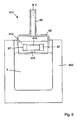
- FIG. 1 of the accompanying drawings there is illustrated a first embodiment of an apparatus, generally indicated as 10, for performing the method of producing a functionally gradient component according to the present invention.
- the method of the present invention is described primarily with reference to the use of alloys based on the aluminium-silicon (Al-Si) system, in particular hypereutectic and hypoeutective Al-Si alloys.
- Al-Si aluminium-silicon
- the method of the present invention is in no way limited to the use of these alloys or other metallic alloys, and may be used with almost any materials which can be converted to a molten state for casting, for example thermoplastics or the like.
- the choice of hypereutectic and hypoeutectic Al-Si alloys simply reflects their dominance in the manufacture of lightweight and wear resistant components in a large number of industries, for example the automotive, aerospace and robotics industry.
- Hypereutectic alloys have a microstructure of silicon needles in a eutectic matrix, and are hard, but brittle if monolithic. Hypoeutectic alloys have a microstructure of pure aluminium phase surrounded by a two phase eutectic matrix. Such alloys are generally tough and ductile, and useful as a structural material.
- the method of the present invention is capable of producing a component with a surface of hypereutectic composition and microstructure, but with a central core of hypoeutectic composition with a gradual change in microstructure between the two. This gives a wear resistant surface but a tough core, these being ideal properties of many components used in mechanical engineering.
- the apparatus 10 of the first embodiment comprises a substantially conventional mould 12 fixed to a rotatable frame F, such that the mould 12 may be held upright as illustrated, or inverted in order to decant material therefrom.
- the Frame F could be of any suitable shape and/or configuration, operable to invert the mould 12.
- the mould 12 defines a cavity 14 in the negative of the shape of a component (not shown) to be produced, which for illustrative purposes is a simple rectangular block.
- Al-Si alloy of hypereutectic composition hereinafter referred to as material A
- material A Al-Si alloy of hypereutectic composition
- Heat from material A is extracted via the mould 12, and thus the material next to the mould 12 cools and solidifies first.
- the thickness of the solid skin grows with time, until it is deemed to be of the correct thickness, wherein the mould 12 is inverted by means of the frame F, the remaining liquid material A therefore being decanted. This leaves a layer of material A solidified along the walls of the mould 12.
- the thickness of the layer of material A will vary depending on the application of the functionally gradient component (not shown) produced, and the conditions under which said component will operate. Other factors may of course influence the thickness of the layer of material A, for example the cost of producing the compontent.
- the material A decanted from the mould 12 is preferably maintained in a molten state in a suitable reservoir (not shown), to be used in producing subsequent components within the mould 12.
- the mould 12 is then returned to the upright position, and a hypoeutectic Al-Si alloy (hereinafter referred to as material B) poured in to fill the remaining space in the cavity 14. If material B is poured into the cavity 14 a sufficiently short interval after the decanting of material A, the layer of material A does not have time to oxidise, and consequently there is no final visible interface between the outer layer of material A and the core of material B. If the method is performed in a reducing gas atmosphere, such oxidation does not occur even for long exposure times.
- material B hypoeutectic Al-Si alloy
- the lack of a distinct interface between material A and material B is also due to the re-melting of the exposed surface of material A by the addition of the molten material B. Convection and mixing in the liquid zone removes the steep composition gradient between material A and material B. In this way, there is a gradual variation in composition and microstructure, from material A to material B, for example from an outer hypereutectic layer to an inner hypoeutectic core.
- FGM functionally gradient material
- Such a functionally gradient component is also less sensitive to stresses which may build up when a component is heated or cooled, as despite there being a likely difference in the thermal coefficient of the two materials forming the functionally gradient component, the gradual change in microstructure from one to the other, as described in detail hereinafter, minimises the effect of the above mentioned stresses.
- the hypereutectic outer layer is allowed to solidify relatively rapidly, resulting in a fine wear resistant surface microstructure. Because the interior liquid hypereutectic alloy is decanted, severe stresses are not set up in the centre of the component to be formed, and also the formation of the large and problematic needles of silicon are avoided, and will not be present in the final component as the central or core alloy will be hypoeutectic. If the entire component were cast from hypereutectic alloy, in order to obtain the hard wear resistant surface, the surface of the component would solidify first, and relatively quickly, but the interior would solidify more slowly, leading to the formation of large silicon needles, which are inherently brittle.
- the component produced by the method of the present invention due to its hypereutectic surface, having high silicon content, has superior surface thermal properties, namely increased strength at high temperature, and higher insulating properties. These are beneficial properties as in wear situations, friction causes heat, and it is important that the resultant high temperatures do not soften the material A. Furthermore, the gradient in the composition from material A to material B renders the material more resistant to thermal fatigue, a condition in which fluctuating or alternating stresses are caused by changes in temperature.
- FIG. 2 of the accompanying drawings there is illustrated a second embodiment of an apparatus , generally indicated as 110, being an exemplary means of performing the method of the present invention.
- the apparatus 110 again comprises a mould 112 defining a cavity 114 for casting a functionally gradient component (not shown) therein.
- the mould 112 is formed from a first sand box 20 of conventional form, the interior of the sand box 20 being filled with compacted sand 22 in order to define the cavity 114, as is conventional foundry practice.
- first sand box 20 and associated sand 22 could be replaced with a mould (not shown) formed from any other suitable material, for example a metal having a higher melting point that the material to be cast within the cavity 114, or a ceramic material.
- the first sand box 20 is mounted above a similar second sand box 24, again being filled with compacted sand 22, to define a pair of channels 26 extending downwardly from a base of the cavity 114.
- the pair of channels 26 extend into a reservoir 28, which is defined within a third sand box 30 being filled with compact sand 22 in order to define the reservoir 28.
- Each sand box 20, 24, 30 is provided with a pair of oppositely disposed handles 32 in order to facilitate the lifting/positioning thereof.
- each sand box 20, 24, 30 is provided with a lug 34 at each corner thereof, each lug 34 defining a bore 36 therethrough.
- a pair of rods 38 preferably formed from carbon or any other material having a suitably high melting point, are inserted downwardly through the cavity 114, and into the channels 26 in order to occlude same, such that molten material may be introduced into the cavity 114 and will not drain downwardly through the channels 26 into the reservoir 28.
- material A preferably a hypereutectic Al-Si alloy
- material B preferably a hypoeutectic Al-Si alloy.
- material A and material B are melted, for example in a suitable furnace, such as an induction furnace or the like.
- Material A is then poured into the cavity 114 in order to fill same.
- the cavity 114 is annular in form, having a central core 40, for example formed from stainless steel or the like.
- the apparatus 110 is adapted to produce an annular component, for example a bushing (not shown) or the like with an inner surface composed of material A.
- the pair of rods 38 While material A is being allowed to solidify around the perimeter of the cavity 114, the pair of rods 38 are maintained in position as shown. When the solidifying layer of material A has reached the desired thickness, the pair of rods 38 are drawn upwardly out of the channels 26, thereby allowing the remaining molten material A to drain downwardly into the reservoir 28. The pair of rods 38 are positioned, when secured within the channels 26, a sufficient distance from the walls of the cavity 114 in order to allow a solidified layer of material A to form.
- a molten material B is then introduced into the cavity 114; around the semi-solid layer of material A. Material B does not drain through the channels 26 as there is a sufficient volume of material A to fill both the reservoir 28 and the channels 26.
- the rods 38 may be heated or made from an insulating material to avoid any metal solidification on the rods 38 themselves.
- the introduction of the molten material B effects re-melting of the interface between material A and material B, thus resulting in a gradient in the microstructure and properties between material A and material B, instead of a step change.
- the method is performed in a reducing gas atmosphere, or at least the steps of decanting material A, and casting material B.
- the apparatus 110 thus enables the method of the present invention to be performed, in order to produce a functionally gradient component.
- FIG. 210 there is illustrated a third embodiment of an apparatus, generally indicated as 210, for performing the method according to the present invention.
- material A having certain mechanical properties
- material B having differing mechanical properties, material A preferably being hypereutectic Al-Si alloy, and material B preferably being hypoeutectic Al-Si alloy.
- the apparatus 210 comprises a mould 212 defining a cavity 214 in the negative shape of a component (not shown) to be cast.
- the cavity 214 is primarily defined within a first sand box 220, filled with compact sand 222 in order to define the shape of the cavity 214, as is conventional foundry practice.
- the first sand box 220 is mounted atop a second sand box 224, which is also filled with compact sand 222, and defines a lower portion of the cavity 214. It will of course be appreciated that the entire cavity 214 could be contained within the first sand box 220. It will also be appreciated that the sand boxes 220, 224 could be replaced with any other suitable mould (not shown), formed from any suitable material.
- Extending from the cavity 214 are a pair of channels 226, for introducing and removing material A and material B from the cavity 214, as will be described in detail hereinafter.
- the sand boxes 220, 224 are also preferably provided with a pair of handles 232 each, for lifting and positioning same.
- the apparatus 210 further comprises a crucible 50 releasably engagable with the second sand box 224, the crucible 50 being of standard refractory type, and being divided into a first chamber 52 and a second chamber 54 for receiving material A and material B respectively.
- the crucible 50 is shown in isolation in figure 4 .
- the apparatus 210 further comprises a lid 56 for the crucible 50, as illustrated in isolation in figure 5 .
- the lid 56 is shaped and dimensioned to provide a pressure tight seal between the crucible 50 and the lid 56.
- the lid 56 is provided with a rim 58 for receiving the upper end of the crucible 50, about which a sealing compound may be provided.
- a gasket (not shown) may be used between the lid 56 and the top of the crucible 50. Pressure is applied to squeeze the gasket (not shown) between the crucible 50 and the lid 56 in order to form a pressure tight seal.
- the lid 56 may be made from a ceramic fibre material and compressed onto the top of the crucible 50, thus forming a pressure tight seal.
- first feed tube 60 which is located, in use, within the first chamber 52
- second feed tube 62 which is located, in use, within the second chamber 54.
- the first and second feed tubes 60, 62 are preferably formed from graphite or ceramic material, or any other material which is capable of withstanding the heat of molten material A and material B.
- the first and second feed tubes 60, 62 are dimensioned to extend to a position adjacent a base of the crucible 50.
- first pump tube 64 which is thus located, in use, within the first chamber 52
- second pump tube 66 which is located, in use, within the second chamber 54.
- the first and second pump tubes 64, 66 are dimensioned to terminate within the upper portion of the crucible 50.
- the first and second pump tubes 64, 66 are also located such as to exit the lid 56 adjacent the perimeter thereof, in order to be accessible when the second sand box 224 is seated atop the lid 56.
- each of the channels 226 are in fluid communication with a respective one of the first feed tube 60 and the second feed tube 62.
- a first valve 68 Disposed within the channel 226 above the first feed tube 60 is a first valve 68, which is operable to permit or prevent the flow of material A between the first chamber 52 and the cavity 214, while a second valve 70 is located within the channel 226 above the second feed tube 62, the second valve 70 being operable to permit or prevent the flow of material B between the second chamber 54 and the cavity 214.
- the first and second valves 68, 70 may be of any suitable form, once capable of withstanding the temperatures which will be experienced within the apparatus 210 during use.
- a quantity of material A is located within the first chamber 52, and a quantity of material B within the second chamber 54.
- the lid 56 is then sealed onto the crucible 50, and the sand boxes 220, 224 mounted thereto as shown.
- the pair of valves 68,70 are initially located in the closed position. If not already done so, material A and material B are then melted, preferably by locating the crucible 50 within a furnace, most preferably an induction furnace. Alternately, material A and B can be melted in another furnace (not shown) and poured into the crucible 50, through their respective feed tubes 60, 62.
- the first valve 68 is then opened, and gas is fed into the first chamber 52, under pressure, through the first pump tube 64.
- the gas pressure therefore forces the molten material A up the first feed tube 60, into the cavity 214 to fill same.
- the pressure is maintained for a specified period of time in order to allow material A to solidify along the surface of the cavity 214.
- the thickness of the solidified layer is controlled by the time the pressure is maintained within the first chamber 52. Once the solidified layer of material A has reached a desired thickness, the pressure is released, and thus the remaining liquid material A drains back down through the first feed tube 60 into the first chamber 52.
- the first valve 68 is then closed, and the second valve 70 opened.
- a device (not shown) could be used to puncture a hole through any solidified metal blocking the second feed tube 62.
- Pressure is then applied to the second chamber 54 via the second pump tube 66, thereby forcing the molten material B upwardly through the second feed tube 62, and into the cavity 214.
- the molten material B re-melts the surface layer of material A within the cavity 214, thereby creating a gradient interface between the two materials A, B.
- the pressure is maintained within the second chamber 54 until material B solidifies within the cavity 214, thereby assisting the avoidance of any shrinkage problems.
- the pressure is then released in order to allow the molten material B within the second feed tube 62 to drop back into the second chamber 54.
- the first sand box 220 may then be removed from the second sand box 224, in order to expose the completed functionally gradient component.
- the crucible 50 or more particularly the first chamber 52 and the second chamber 54, could be replaced with two separate crucibles (not shown), which may be housed within an airtight chamber (not shown), preferably containing an induction furnace (not shown).
- the chamber may then be pressurised in order to pump material A and material B into the mould, with the use of suitable valving (not shown) preventing both material A and material B from being pumped into the mould at the same time.
- two separate chambers could be used to house the two crucibles (not shown), if different holding temperatures were required for material A and material B.
- valve block 80 comprising a body 82 having a first through bore 84 and a second through bore 86 therein, each through bore 84, 86 having a valve (not shown) in operative association therewith, the valves (not shown) being operable by a respective first handle 88 and second handle 90.
- valve block 80 is preferably provided with one or more heating chambers 92 extending inwardly of the body 82, into which heating elements (not shown) may be inserted in order to prevent solidification of material A or material B within the valve block 80.
- valve block 80 would then preferably replace the entire second sand box 224, and the valves 68, 70, the first sand box 220 would then be mounted directly on the valve block 80. With such an arrangement, the entire cavity 214 would need to be located within the first sand box 220 or any other suitable mould (not shown).
- the use of the valve block 80 avoids the need to carefully and accurately locate the valves 68, 70 within the compacted sand 222 of the second sand box 224, which can be a time consuming and difficult task.
- FIG. 8 and 9 there is illustrates a fourth embodiment of an apparatus , generally indicated as 410, for performing the method of producing a functionally gradient component according to the present invention.
- the apparatus 410 is adapted to perform the vacuum casting of a functionally gradient component (not shown), as described hereinafter.
- the apparatus 410 comprises a mould 412, preferably formed from compacted sand, the mould 412 defining a cavity 414 therein, for casting the functionally gradient component (not shown) therein.
- the mould 412 is clamped or held within a vacuum cup 95, between which and the mould 412 is a fluid tight seal.
- the vacuum cup 95 is substantially circular in cross section, in the embodiment illustrated, it will be appreciated that any other suitable shape could be used.
- an suction tube 96 Extending from the vacuum cup 95 is an suction tube 96 which, in use, is connected to a vacuum pump (not shown) or the like, in order to be capable of applying a negative pressure or vacuum to the mould 412, via the vacuum cup 95.
- a vacuum will thus be created within the cavity 414.
- the mould is provided with a gate or channel 426 on the underside thereof, provided external access to the cavity 414.
- the mould may also be provided with chills 97 disposed at various locations around the mould 414, in order to control solidification of material within the mould 414, and thus the thickness of the material adjacent said chills 97.
- the mould 412 held within the vacuum cup 95, is positioned above a furnace 450, preferably an induction furnace, containing molten material A.
- the mould 414 is then lowered into material A, as illustrated in Figure 9 , and a vacuum applied to the vacuum cup 95, and thus the cavity 414, by drawing air up through the suction tube 96, in the direction of arrow V.
- Material A is therefore drawn up into the cavity 414, and begins to solidify against the walls thereof.
- the vacuum is released from the vacuum cup 95, and the molten portion of material A within the cavity 414 pours back into the furnace 450 under gravity.
- the mould 412 and the vacuum cup 95 are quickly transferred to a second furnace (not shown), preferably of the same type as the first furnace 450, although containing molten material B (not shown).
- the above process is then repeated, with the mould 412 being lowered into material B, and a vacuum being applied to the cavity 414, in order to draw molten material B into the cavity 414 to form a core within the skin of material A.
- the vacuum is maintained until material B is fully solidified.
- material B could be release back into the second furnace (not shown) after the partial solidification thereof, and a third material (not shown) introduced into the cavity 414, and so on.
- CLA Countergravity Low pressure Air melt
- CLV Coutergravity Low pressure Vacuum melt
- suitable reservoirs of hot material normally known as feeders (not shown) could be provided to control the solidification rates of material A and material B, particularly to avoid solidification of the runners before material A and/or material B in the cavity 214, as this could lead to shrinkage problems and difficulties with using a second mould (not shown) in a production run.
- suitable chills could be provided around the mould 212, in order to control the solidification rates and to target material A towards specific areas of the component to be produced, for example on a particular surface or part of a surface.
- a metal mould (not shown), or a mould of any other suitable material could be used with heated or cooled sections to control solidification.
- the Hitchiner Process is an investment casting process where molten metal is drawn up into a mould (not shown) by applying a partial vacuum to an air tight chamber around the mould.
- a tube (not shown) extends downwardly from the mould into a bath or crucible of the molten metal, thereby facilitating suction of the molten metal into the mould. Drawing the molten metal up into the mould in this fashion allows for a very controlled filling rate and very low levels of impurities in the cast product (not shown).
- the method of the present invention could be adapted to the Hitchiner process by providing two baths of molten metal, one containing material A, and one containing material B.
- the mould (not shown) may be prepared in a similar fashion to the standard Hitchiner process, but may have chills (not shown) inserted at desired locations in order to produce increased solidification points for material A.
- the mould is then placed above the bath of material A, with the gate tube below the surface of the molten material A.
- Material A is then drawn up into the mould by applying a vacuum to the mould, and after a specified time, when a sufficient amount of material A has solidified on the walls of the mould (not shown), or has solidified only on the chills (not shown), the vacuum is released and the remaining molten portion of material A is decanted back into the bath or crucible (not shown).
- the mould or the crucible is then moved so that the mould is above the second bath or crucible (not shown) containing molten material B, again with the tube of the mould extending below the surface of material B.
- the vacuum is again used to draw material B upwardly to fill the remaining part of the mould.
- Material B combines with the mushy exposed surface layer of material A and forms a gradient microstructure. When material B is fully solidified in the mould the vacuum is released. If desired, the vacuum could be released after the individual components are solidified but before a runner (not shown) solidifies in order to aid in the manufacturing process.
- a further casting process which may be adapted for use with the method of the present invention is the Cosworth process, which is a variation on the low pressure casting process.
- the key difference with the Cosworth process is the use of metal pumps to transfer molten metal into a mould (not shown), rather than applying a gas pressure difference to a sealed crucible (not shown).
- the method of producing a functionally gradient component according to the present invention is primarily intended to be employed in producing a finished or substantially finished product (not shown), the method of the present invention also has the potential to produce blooms, slabs, billets (not shown) etc for the production of wrought metal products or the like.
- an ingot could be produced according to the method of the present invention, using any one of the processes described above, and a functionally gradient wrought metal product (not shown) could then be produced using one or more of a number of extrusion processes or the like, for example hot rolling, cold drawing, etc.
- Such an ingot (not shown) could also be used in a forging process, for example drop forging or the like.
- the method according to the present invention may also be used to produce a bulk metallic glass (BMG) component, or a component having an outer layer of a bulk metallic glass.
- BMG is a relatively new material produced by super cooling liquid metal to form a vitreous solid having unusually high strength, wear and corrosion resistance, and elasticity, in addition to a number of other beneficial characteristics. This new type of material was discovered at the California Institute of Technology in 1960, and has been the subject of much research and commercial activity since, particularly over the last decade. However, heat conduction in BMG is slow, and thus the required cooling rate can only be achieved for a relatively small casting thickness.
- the method of the present invention could be used to create BMG through serial casting and decanting, allowing a BMG component to be built up in layers, by virtue of only a thin layer solidifying at a given time, allowing the required cooling rates to be achieved.
- This method could also be adapted to combine a BMG with a crystalline material, with an intermediate or a transitional layer being a partially glassy zone. This process would involve the initial casting of a layer of BMG by using a sufficiently high cooling rate at a wall or portions of a wall of a mould (not shown), and then decanting the remaining liquid material, and subsequently casting a crystalline core inside the BMG layer. The transitional layer between the BMG outer layer and the crystalline core would then be a partially glassy zone.
- the present invention therefore provides a relatively simple method of producing a functionally gradient component, in particular a lightweight metal component formed from, for example two or more aluminium alloys, which has an outer layer with particular properties, for example wear resistance, and at least one inner layer or core having different properties, for example shock resistance or the like.
Abstract
Description
- The present invention is concerned with a method for producing a functionally gradient component, in particular a component formed from two or more materials such as metal, and more particularly a component formed from two or more aluminium alloys based on the aluminium - silicon (Al-Si) system, or other binary or multicomponent alloys such as Cu-Sn or Fe-C.
- There is a clear need in engineering for light weight yet wear resistant parts, produced in an economic manner. Typically, materials which are resistant to wear are often inherently brittle, and therefore if used in moving parts which are dynamically loaded (for example in an engine), there is a risk of fracture. One way of overcoming this problem is via the application of a hard wearing exterior coating to a tough and ductile core, for example a ceramic coating on a metal core. The conventional means of providing such wear resistant surface coatings are based on plasmas, e.g. physical vapour deposition (PVD), chemical vapour deposition (CVD), or the like, and thus require expensive equipment, while only depositing a very thin layer, normally in the order of micrometers, which will quickly wear during use. In addition, in coated substrates, severe stresses may build up when the component is subject to heating or cooling, due to the mismatch of thermal expansion co-efficients between the coating and its substrate. This may result in spalling the coating, and delamination of the substrate-coating interface.
- Another light yet wear resistant material is a metal matrix composite (MMC). This is a material with a metallic matrix incorporating reinforcing ceramic particles, for example of silicon carbide (SiC). It is however problematic to ensure proper adhesion (wetting) between such particles and the metallic matrix, normally aluminium. In addition, when these materials are melted for casting, the ceramic particles tend to agglomerate or sediment to the bottom of the component.
- Porosity is a feature of materials thus processed, and is very difficult to avoid. The raw materials are also relatively expensive.
- Spray casting is a further method by which fine microstructures may be formed in hypereutectic Al-Si alloys. The process involves atomisation of a stream of molten metal with an inert gas, and deposition onto a moving substrate making the process relatively expensive, and incapable of producing components to a near net shape - only preliminary shapes may be produced, which require subsequent processing to form useful components.
-
US3192581 discloses a novel method and apparatus for producing a composite metal article. -
US2841846 discloses a method of making metal castings. -
JP56009044 -
DE2355745 discloses a process for manufacturing composite metal parts, and in particular rolling mill rolls. -
US399295 discloses a roll or pinion formed of a steel body and having a thin shell or facing of chilled cast iron upon the neck or facing surfaces. - It is therefore an object of the present invention to provide a novel method of producing a functionally gradient component comprising at least one outer layer of a first material having certain physical characteristics, and an inner core of a second material having different physical characteristics, with a gradual change in microstructure between the first and the second material.
- The present invention therefore provides a method of producing a functionally gradient component according to claim 1. Preferred method steps are claimed in the dependent claims 2 - 9.
- As used herein, the term "functionally gradient component" is intended to mean a component having an outer layer of a first material, and an inner core of a second material, there being a gradual change in microstructure across the interface between the two materials.
- As used herein, the term "molten state" is intended to mean that state of a material, for example a metal, which is normally achieved by heating the material to a certain temperature or within a certain temperature range and which will allow the material to flow, for example into or out of a mould or the like, whether under the influence of gravity or with additional assistance, and to conform to the shape of the mould.
- As used herein, the term "component" is intended to mean a finished or substantially finished end product ready for use in an intended application, in addition to meaning a product which may require one or more subsequent processing steps prior to be considered a finished product or being ready for use in a particular application.
- The present invention will now be described with reference to the accompanying drawings, in which;
-
Figure 1 illustrates a perspective view of a first embodiment of an apparatus for performing the method of the present invention; -
Figure 2 illustrates a sectioned side elevation of a second embodiment of an apparatus for performing the method of the present invention; -
Figure 3 illustrates a sectioned side elevation of a third embodiment of an apparatus for performing the method of the present invention; -
Figure 4 illustrates a sectioned side elevation of a crucible forming part of the apparatus offigure 3 ; -
Figure 5 illustrates a perspective view of a lid for the crucible illustrated infigure 4 ; -
Figure 6 illustrates a sectioned side elevation of the apparatus illustrated infigure 3 , having a metal A and a metal B located therein; -
Figure 7 illustrates a perspective view of a valve block which may be used with the apparatus illustrated infigure 3 ; -
Figure 8 illustrates a perspective sectioned view of a fourth embodiment of an apparatus for performing the method of the present invention, in which a mould is in a raised position; and -
Figure 9 illustrates a sectioned side elevation of the apparatus ofFigure 9 , in which the mould is in a lowered position. - Referring now to
figure 1 of the accompanying drawings, there is illustrated a first embodiment of an apparatus, generally indicated as 10, for performing the method of producing a functionally gradient component according to the present invention. Throughout the following description, the method of the present invention is described primarily with reference to the use of alloys based on the aluminium-silicon (Al-Si) system, in particular hypereutectic and hypoeutective Al-Si alloys. However, the method of the present invention is in no way limited to the use of these alloys or other metallic alloys, and may be used with almost any materials which can be converted to a molten state for casting, for example thermoplastics or the like. The choice of hypereutectic and hypoeutectic Al-Si alloys simply reflects their dominance in the manufacture of lightweight and wear resistant components in a large number of industries, for example the automotive, aerospace and robotics industry. - Hypereutectic alloys have a microstructure of silicon needles in a eutectic matrix, and are hard, but brittle if monolithic. Hypoeutectic alloys have a microstructure of pure aluminium phase surrounded by a two phase eutectic matrix. Such alloys are generally tough and ductile, and useful as a structural material. The method of the present invention, as will be described in detail hereinafter, is capable of producing a component with a surface of hypereutectic composition and microstructure, but with a central core of hypoeutectic composition with a gradual change in microstructure between the two. This gives a wear resistant surface but a tough core, these being ideal properties of many components used in mechanical engineering.
- Thus the
apparatus 10 of the first embodiment, as illustrated infigure 1 , comprises a substantiallyconventional mould 12 fixed to a rotatable frame F, such that themould 12 may be held upright as illustrated, or inverted in order to decant material therefrom. It will therefore be appreciated that the Frame F could be of any suitable shape and/or configuration, operable to invert themould 12. - The
mould 12 defines acavity 14 in the negative of the shape of a component (not shown) to be produced, which for illustrative purposes is a simple rectangular block. Al-Si alloy of hypereutectic composition (hereinafter referred to as material A) is melted, and poured into thecavity 14. Heat from material A is extracted via themould 12, and thus the material next to themould 12 cools and solidifies first. The thickness of the solid skin grows with time, until it is deemed to be of the correct thickness, wherein themould 12 is inverted by means of the frame F, the remaining liquid material A therefore being decanted. This leaves a layer of material A solidified along the walls of themould 12. The thickness of the layer of material A will vary depending on the application of the functionally gradient component (not shown) produced, and the conditions under which said component will operate. Other factors may of course influence the thickness of the layer of material A, for example the cost of producing the compontent. The material A decanted from themould 12 is preferably maintained in a molten state in a suitable reservoir (not shown), to be used in producing subsequent components within themould 12. - The
mould 12 is then returned to the upright position, and a hypoeutectic Al-Si alloy (hereinafter referred to as material B) poured in to fill the remaining space in thecavity 14. If material B is poured into the cavity 14 a sufficiently short interval after the decanting of material A, the layer of material A does not have time to oxidise, and consequently there is no final visible interface between the outer layer of material A and the core of material B. If the method is performed in a reducing gas atmosphere, such oxidation does not occur even for long exposure times. - The lack of a distinct interface between material A and material B is also due to the re-melting of the exposed surface of material A by the addition of the molten material B. Convection and mixing in the liquid zone removes the steep composition gradient between material A and material B. In this way, there is a gradual variation in composition and microstructure, from material A to material B, for example from an outer hypereutectic layer to an inner hypoeutectic core. The result is a functionally gradient material (FGM) or component, in which there is an outer layer having certain mechanical properties, for example being hard and wear resistant, and a core having different mechanical properties, for example being softer, but tougher and more ductile. Such a functionally gradient component is also less sensitive to stresses which may build up when a component is heated or cooled, as despite there being a likely difference in the thermal coefficient of the two materials forming the functionally gradient component, the gradual change in microstructure from one to the other, as described in detail hereinafter, minimises the effect of the above mentioned stresses.
- Referring specifically to hypereutectic and hypoeutectic Al-Si alloys, the hypereutectic outer layer is allowed to solidify relatively rapidly, resulting in a fine wear resistant surface microstructure. Because the interior liquid hypereutectic alloy is decanted, severe stresses are not set up in the centre of the component to be formed, and also the formation of the large and problematic needles of silicon are avoided, and will not be present in the final component as the central or core alloy will be hypoeutectic. If the entire component were cast from hypereutectic alloy, in order to obtain the hard wear resistant surface, the surface of the component would solidify first, and relatively quickly, but the interior would solidify more slowly, leading to the formation of large silicon needles, which are inherently brittle. Due to stresses caused by solidification and shrinkage, the casting could even break apart before being completely solidified. Even if the casting did not break, the large internal needle shaped silicon crystals would provide a path for crack propagation, making the material brittle. These are some of the problems that are avoided with the method of the present invention.
- Furthermore, the component produced by the method of the present invention, due to its hypereutectic surface, having high silicon content, has superior surface thermal properties, namely increased strength at high temperature, and higher insulating properties. These are beneficial properties as in wear situations, friction causes heat, and it is important that the resultant high temperatures do not soften the material A. Furthermore, the gradient in the composition from material A to material B renders the material more resistant to thermal fatigue, a condition in which fluctuating or alternating stresses are caused by changes in temperature.
- Referring now to
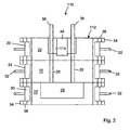
figure 2 of the accompanying drawings, there is illustrated a second embodiment of an apparatus , generally indicated as 110, being an exemplary means of performing the method of the present invention. Theapparatus 110 again comprises amould 112 defining acavity 114 for casting a functionally gradient component (not shown) therein. Themould 112 is formed from afirst sand box 20 of conventional form, the interior of thesand box 20 being filled with compactedsand 22 in order to define thecavity 114, as is conventional foundry practice. It will of course be appreciated that thefirst sand box 20 and associatedsand 22 could be replaced with a mould (not shown) formed from any other suitable material, for example a metal having a higher melting point that the material to be cast within thecavity 114, or a ceramic material. - The
first sand box 20 is mounted above a similarsecond sand box 24, again being filled with compactedsand 22, to define a pair ofchannels 26 extending downwardly from a base of thecavity 114. The pair ofchannels 26 extend into areservoir 28, which is defined within athird sand box 30 being filled withcompact sand 22 in order to define thereservoir 28. - Each
sand box sand box lug 34 at each corner thereof, eachlug 34 defining abore 36 therethrough. Thus, when thesand boxes bores 36 inadjacent lugs 34 are aligned, and thus locating pins (not shown) may be passed therethrough in order to secure thesand boxes - In use, a pair of
rods 38, preferably formed from carbon or any other material having a suitably high melting point, are inserted downwardly through thecavity 114, and into thechannels 26 in order to occlude same, such that molten material may be introduced into thecavity 114 and will not drain downwardly through thechannels 26 into thereservoir 28. - Again in describing the method of the present invention as implemented with the
apparatus 110, reference will be made to material A, preferably a hypereutectic Al-Si alloy, and material B, preferably a hypoeutectic Al-Si alloy. Initially, material A and material B are melted, for example in a suitable furnace, such as an induction furnace or the like. Material A is then poured into thecavity 114 in order to fill same. It should be noted that thecavity 114 is annular in form, having acentral core 40, for example formed from stainless steel or the like. Thus theapparatus 110 is adapted to produce an annular component, for example a bushing (not shown) or the like with an inner surface composed of material A. While material A is being allowed to solidify around the perimeter of thecavity 114, the pair ofrods 38 are maintained in position as shown. When the solidifying layer of material A has reached the desired thickness, the pair ofrods 38 are drawn upwardly out of thechannels 26, thereby allowing the remaining molten material A to drain downwardly into thereservoir 28. The pair ofrods 38 are positioned, when secured within thechannels 26, a sufficient distance from the walls of thecavity 114 in order to allow a solidified layer of material A to form. - Once the
rods 38 have been removed, and the molten material A has drained into thereservoir 28, a molten material B is then introduced into thecavity 114; around the semi-solid layer of material A. Material B does not drain through thechannels 26 as there is a sufficient volume of material A to fill both thereservoir 28 and thechannels 26. Therods 38 may be heated or made from an insulating material to avoid any metal solidification on therods 38 themselves. - The introduction of the molten material B effects re-melting of the interface between material A and material B, thus resulting in a gradient in the microstructure and properties between material A and material B, instead of a step change. Again it is preferable that the method is performed in a reducing gas atmosphere, or at least the steps of decanting material A, and casting material B.
- The
apparatus 110 thus enables the method of the present invention to be performed, in order to produce a functionally gradient component. - Referring now to
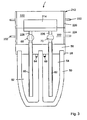
figures 3 to 6 , there is illustrated a third embodiment of an apparatus, generally indicated as 210, for performing the method according to the present invention. Again in describing this third embodiment, reference will be made to material A, having certain mechanical properties, and material B, having differing mechanical properties, material A preferably being hypereutectic Al-Si alloy, and material B preferably being hypoeutectic Al-Si alloy. - The
apparatus 210 comprises amould 212 defining acavity 214 in the negative shape of a component (not shown) to be cast. Thecavity 214 is primarily defined within afirst sand box 220, filled withcompact sand 222 in order to define the shape of thecavity 214, as is conventional foundry practice. Thefirst sand box 220 is mounted atop asecond sand box 224, which is also filled withcompact sand 222, and defines a lower portion of thecavity 214. It will of course be appreciated that theentire cavity 214 could be contained within thefirst sand box 220. It will also be appreciated that thesand boxes cavity 214 are a pair ofchannels 226, for introducing and removing material A and material B from thecavity 214, as will be described in detail hereinafter. Thesand boxes handles 232 each, for lifting and positioning same. - The
apparatus 210 further comprises acrucible 50 releasably engagable with thesecond sand box 224, thecrucible 50 being of standard refractory type, and being divided into afirst chamber 52 and asecond chamber 54 for receiving material A and material B respectively. Thecrucible 50 is shown in isolation infigure 4 . - The
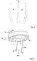
apparatus 210 further comprises alid 56 for thecrucible 50, as illustrated in isolation infigure 5 . Thelid 56 is shaped and dimensioned to provide a pressure tight seal between thecrucible 50 and thelid 56. To this end, thelid 56 is provided with arim 58 for receiving the upper end of thecrucible 50, about which a sealing compound may be provided. - Alternately, a gasket (not shown) may be used between the
lid 56 and the top of thecrucible 50. Pressure is applied to squeeze the gasket (not shown) between thecrucible 50 and thelid 56 in order to form a pressure tight seal. - Alternately, the
lid 56 may be made from a ceramic fibre material and compressed onto the top of thecrucible 50, thus forming a pressure tight seal. - Extending through the
lid 56 is afirst feed tube 60 which is located, in use, within thefirst chamber 52, and asecond feed tube 62 which is located, in use, within thesecond chamber 54. The first andsecond feed tubes second feed tubes crucible 50. - Also extending through the
lid 56 is afirst pump tube 64 which is thus located, in use, within thefirst chamber 52, and asecond pump tube 66 which is located, in use, within thesecond chamber 54. The first andsecond pump tubes crucible 50. The first andsecond pump tubes lid 56 adjacent the perimeter thereof, in order to be accessible when thesecond sand box 224 is seated atop thelid 56. - As illustrated in
figure 3 , when thesecond sand box 224 is mounted to thelid 56, each of thechannels 226 are in fluid communication with a respective one of thefirst feed tube 60 and thesecond feed tube 62. Thus there is provided a path from thefirst reservoir 52 into thecavity 214, and from thesecond chamber 54 into thecavity 214. Disposed within thechannel 226 above thefirst feed tube 60 is afirst valve 68, which is operable to permit or prevent the flow of material A between thefirst chamber 52 and thecavity 214, while asecond valve 70 is located within thechannel 226 above thesecond feed tube 62, thesecond valve 70 being operable to permit or prevent the flow of material B between thesecond chamber 54 and thecavity 214. The first andsecond valves apparatus 210 during use. - Therefore, in use, and referring in particular to
figure 6 , a quantity of material A is located within thefirst chamber 52, and a quantity of material B within thesecond chamber 54. Thelid 56 is then sealed onto thecrucible 50, and thesand boxes valves crucible 50 within a furnace, most preferably an induction furnace. Alternately, material A and B can be melted in another furnace (not shown) and poured into thecrucible 50, through theirrespective feed tubes - The
first valve 68 is then opened, and gas is fed into thefirst chamber 52, under pressure, through thefirst pump tube 64. The gas pressure therefore forces the molten material A up thefirst feed tube 60, into thecavity 214 to fill same. The pressure is maintained for a specified period of time in order to allow material A to solidify along the surface of thecavity 214. The thickness of the solidified layer is controlled by the time the pressure is maintained within thefirst chamber 52. Once the solidified layer of material A has reached a desired thickness, the pressure is released, and thus the remaining liquid material A drains back down through thefirst feed tube 60 into thefirst chamber 52. - The
first valve 68 is then closed, and thesecond valve 70 opened. If necessary, a device (not shown) could be used to puncture a hole through any solidified metal blocking thesecond feed tube 62. Pressure is then applied to thesecond chamber 54 via thesecond pump tube 66, thereby forcing the molten material B upwardly through thesecond feed tube 62, and into thecavity 214. The molten material B re-melts the surface layer of material A within thecavity 214, thereby creating a gradient interface between the two materials A, B. The pressure is maintained within thesecond chamber 54 until material B solidifies within thecavity 214, thereby assisting the avoidance of any shrinkage problems. The pressure is then released in order to allow the molten material B within thesecond feed tube 62 to drop back into thesecond chamber 54. Thefirst sand box 220 may then be removed from thesecond sand box 224, in order to expose the completed functionally gradient component. - It will be appreciated that the
crucible 50, or more particularly thefirst chamber 52 and thesecond chamber 54, could be replaced with two separate crucibles (not shown), which may be housed within an airtight chamber (not shown), preferably containing an induction furnace (not shown). The chamber may then be pressurised in order to pump material A and material B into the mould, with the use of suitable valving (not shown) preventing both material A and material B from being pumped into the mould at the same time. Alternatively, two separate chambers (not shown) could be used to house the two crucibles (not shown), if different holding temperatures were required for material A and material B. - Referring to
figure 7 , the first andsecond valves valve block 80 comprising abody 82 having a first throughbore 84 and a second throughbore 86 therein, each throughbore first handle 88 andsecond handle 90. In addition, thevalve block 80 is preferably provided with one ormore heating chambers 92 extending inwardly of thebody 82, into which heating elements (not shown) may be inserted in order to prevent solidification of material A or material B within thevalve block 80. Thevalve block 80 would then preferably replace the entiresecond sand box 224, and thevalves first sand box 220 would then be mounted directly on thevalve block 80. With such an arrangement, theentire cavity 214 would need to be located within thefirst sand box 220 or any other suitable mould (not shown). The use of thevalve block 80 avoids the need to carefully and accurately locate thevalves sand 222 of thesecond sand box 224, which can be a time consuming and difficult task. - Referring to
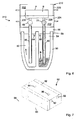
Figures 8 and9 , there is illustrates a fourth embodiment of an apparatus , generally indicated as 410, for performing the method of producing a functionally gradient component according to the present invention. Theapparatus 410 is adapted to perform the vacuum casting of a functionally gradient component (not shown), as described hereinafter. Theapparatus 410 comprises amould 412, preferably formed from compacted sand, themould 412 defining acavity 414 therein, for casting the functionally gradient component (not shown) therein. Themould 412 is clamped or held within avacuum cup 95, between which and themould 412 is a fluid tight seal. Although thevacuum cup 95 is substantially circular in cross section, in the embodiment illustrated, it will be appreciated that any other suitable shape could be used. - Extending from the
vacuum cup 95 is ansuction tube 96 which, in use, is connected to a vacuum pump (not shown) or the like, in order to be capable of applying a negative pressure or vacuum to themould 412, via thevacuum cup 95. As themould 412 is formed from a porous sand, a vacuum will thus be created within thecavity 414. The mould is provided with a gate orchannel 426 on the underside thereof, provided external access to thecavity 414. The mould may also be provided withchills 97 disposed at various locations around themould 414, in order to control solidification of material within themould 414, and thus the thickness of the material adjacent saidchills 97. - Thus, in use, the
mould 412, held within thevacuum cup 95, is positioned above afurnace 450, preferably an induction furnace, containing molten material A. Themould 414 is then lowered into material A, as illustrated inFigure 9 , and a vacuum applied to thevacuum cup 95, and thus thecavity 414, by drawing air up through thesuction tube 96, in the direction of arrow V. Material A is therefore drawn up into thecavity 414, and begins to solidify against the walls thereof. After material A has reached a desired thickness, the vacuum is released from thevacuum cup 95, and the molten portion of material A within thecavity 414 pours back into thefurnace 450 under gravity. - The
mould 412 and thevacuum cup 95 are quickly transferred to a second furnace (not shown), preferably of the same type as thefirst furnace 450, although containing molten material B (not shown). The above process is then repeated, with themould 412 being lowered into material B, and a vacuum being applied to thecavity 414, in order to draw molten material B into thecavity 414 to form a core within the skin of material A. The vacuum is maintained until material B is fully solidified. - It will of course be appreciated that material B could be release back into the second furnace (not shown) after the partial solidification thereof, and a third material (not shown) introduced into the
cavity 414, and so on. - This type of vacuum casting is generally known as Countergravity Low pressure Air melt (CLA). A common variant is the Coutergravity Low pressure Vacuum melt (CLV) process. The difference between the two processes is that with CLA, metal is normally melted open to the atmosphere, while with CLV, the metal is melted in a vacuum. CLV is therefore generally used for reactive metals that cannot be melted in air.
- It should be noted that the above described embodiments are relatively simple means of effecting the method of the present invention, and various modifications or improvements could be made to same. For example, suitable reservoirs of hot material, normally known as feeders (not shown) could be provided to control the solidification rates of material A and material B, particularly to avoid solidification of the runners before material A and/or material B in the
cavity 214, as this could lead to shrinkage problems and difficulties with using a second mould (not shown) in a production run. In addition, suitable chills (not shown) could be provided around themould 212, in order to control the solidification rates and to target material A towards specific areas of the component to be produced, for example on a particular surface or part of a surface. Alternatively, a metal mould (not shown), or a mould of any other suitable material, could be used with heated or cooled sections to control solidification. - It should also be apparent that any other suitable casting process could be adapted for use with the method according to the present invention. For example, the Hitchiner Process is an investment casting process where molten metal is drawn up into a mould (not shown) by applying a partial vacuum to an air tight chamber around the mould. A tube (not shown) extends downwardly from the mould into a bath or crucible of the molten metal, thereby facilitating suction of the molten metal into the mould. Drawing the molten metal up into the mould in this fashion allows for a very controlled filling rate and very low levels of impurities in the cast product (not shown). Thus the method of the present invention could be adapted to the Hitchiner process by providing two baths of molten metal, one containing material A, and one containing material B. The mould (not shown) may be prepared in a similar fashion to the standard Hitchiner process, but may have chills (not shown) inserted at desired locations in order to produce increased solidification points for material A. The mould is then placed above the bath of material A, with the gate tube below the surface of the molten material A. Material A is then drawn up into the mould by applying a vacuum to the mould, and after a specified time, when a sufficient amount of material A has solidified on the walls of the mould (not shown), or has solidified only on the chills (not shown), the vacuum is released and the remaining molten portion of material A is decanted back into the bath or crucible (not shown). The mould or the crucible is then moved so that the mould is above the second bath or crucible (not shown) containing molten material B, again with the tube of the mould extending below the surface of material B. The vacuum is again used to draw material B upwardly to fill the remaining part of the mould. Material B combines with the mushy exposed surface layer of material A and forms a gradient microstructure. When material B is fully solidified in the mould the vacuum is released. If desired, the vacuum could be released after the individual components are solidified but before a runner (not shown) solidifies in order to aid in the manufacturing process.
- A further casting process which may be adapted for use with the method of the present invention is the Cosworth process, which is a variation on the low pressure casting process. The key difference with the Cosworth process is the use of metal pumps to transfer molten metal into a mould (not shown), rather than applying a gas pressure difference to a sealed crucible (not shown).
- It is also worth noting that while the method of producing a functionally gradient component according to the present invention is primarily intended to be employed in producing a finished or substantially finished product (not shown), the method of the present invention also has the potential to produce blooms, slabs, billets (not shown) etc for the production of wrought metal products or the like. For example, an ingot (not shown) could be produced according to the method of the present invention, using any one of the processes described above, and a functionally gradient wrought metal product (not shown) could then be produced using one or more of a number of extrusion processes or the like, for example hot rolling, cold drawing, etc. Such an ingot (not shown) could also be used in a forging process, for example drop forging or the like.
- The method according to the present invention may also be used to produce a bulk metallic glass (BMG) component, or a component having an outer layer of a bulk metallic glass. BMG is a relatively new material produced by super cooling liquid metal to form a vitreous solid having unusually high strength, wear and corrosion resistance, and elasticity, in addition to a number of other beneficial characteristics. This new type of material was discovered at the California Institute of Technology in 1960, and has been the subject of much research and commercial activity since, particularly over the last decade. However, heat conduction in BMG is slow, and thus the required cooling rate can only be achieved for a relatively small casting thickness. The method of the present invention could be used to create BMG through serial casting and decanting, allowing a BMG component to be built up in layers, by virtue of only a thin layer solidifying at a given time, allowing the required cooling rates to be achieved. This method could also be adapted to combine a BMG with a crystalline material, with an intermediate or a transitional layer being a partially glassy zone. This process would involve the initial casting of a layer of BMG by using a sufficiently high cooling rate at a wall or portions of a wall of a mould (not shown), and then decanting the remaining liquid material, and subsequently casting a crystalline core inside the BMG layer. The transitional layer between the BMG outer layer and the crystalline core would then be a partially glassy zone.
- The present invention therefore provides a relatively simple method of producing a functionally gradient component, in particular a lightweight metal component formed from, for example two or more aluminium alloys, which has an outer layer with particular properties, for example wear resistance, and at least one inner layer or core having different properties, for example shock resistance or the like.
Claims (9)
- A method of producing a functionally gradient component, the method comprising introducing a first material, in a molten state, into a mould (12); allowing a layer of the first material to at least partially solidify against a wall of the mould (12); decanting the remaining molten portion of the first material; introducing a second material, in a molten state, into the mould (12);
characterised in that the method further comprises the step of:remelting the exposed surface of the first material by the addition of the molten second material such as to effect convection and mixing at the interface between the first and second materials to produce a gradual change in microstructure between the first and second materials. - A method according to claim 1 in which at least the decanting step is undertaken in a reducing gas atmosphere.
- A method according to claim 1 or 2 comprising immediately introducing the second material into the mould (12) after the decanting of the first material such as to prevent oxidation of the layer of the first material.
- A method according to any preceding claim comprising the additional step of altering the temperature at one or more locations on the wall of the mould (12), prior to introducing the first material, in order to achieve a desired thickness of the layer of the first material at said one or more locations.
- A method according to any preceding claim comprising, in the step of introducing the first material, introducing the first material into the mould (12) under pressure.
- A method according to any preceding claim comprising, in the step of introducing the second material, introducing the second material into the mould (12) under pressure.
- A method according to any preceding claim comprising the additional step of pre-heating at least a portion of the mould (12) prior to the introduction of the first material.
- A method according to claim 6 or 7 comprising the additional step of maintaining the second material under pressure within the mould; allowing the second material to substantially solidify; and removing the pressure from the second material.
- A method according to any preceding claim comprising the additional steps of allowing a layer of the second material to at least partially solidify on the layer of the first material; decanting the remaining molten portion of the second material; and introducing a third material, in a molten state, into the mould (12).
Applications Claiming Priority (2)
| Application Number | Priority Date | Filing Date | Title |
|---|---|---|---|
| IE20040502 | 2004-07-26 | ||
| PCT/EP2005/008137 WO2006010601A2 (en) | 2004-07-26 | 2005-07-25 | A method for producing a functionally gradient component |
Publications (2)
| Publication Number | Publication Date |
|---|---|
| EP1778426A2 EP1778426A2 (en) | 2007-05-02 |
| EP1778426B1 true EP1778426B1 (en) | 2011-12-07 |
Family
ID=35033314
Family Applications (1)
| Application Number | Title | Priority Date | Filing Date |
|---|---|---|---|
| EP05762955A Not-in-force EP1778426B1 (en) | 2004-07-26 | 2005-07-25 | A method for producing a functionally gradient component |
Country Status (8)
| Country | Link |
|---|---|
| US (1) | US7874344B2 (en) |
| EP (1) | EP1778426B1 (en) |
| JP (1) | JP2008507410A (en) |
| KR (1) | KR20070095863A (en) |
| CN (1) | CN101018630B (en) |
| AT (1) | ATE536228T1 (en) |
| ES (1) | ES2381197T3 (en) |
| WO (1) | WO2006010601A2 (en) |
Families Citing this family (7)
| Publication number | Priority date | Publication date | Assignee | Title |
|---|---|---|---|---|
| US20090095436A1 (en) * | 2007-10-11 | 2009-04-16 | Jean-Louis Pessin | Composite Casting Method of Wear-Resistant Abrasive Fluid Handling Components |
| US8448690B1 (en) * | 2008-05-21 | 2013-05-28 | Alcoa Inc. | Method for producing ingot with variable composition using planar solidification |
| US10099283B2 (en) * | 2015-12-17 | 2018-10-16 | General Electric Company | Method and assembly for forming components having an internal passage defined therein |
| US20180347011A1 (en) * | 2017-05-31 | 2018-12-06 | GM Global Technology Operations LLC | System and method to stabilize transition metal precipitates in cast aluminum alloys during primary solidification |
| DE202017105293U1 (en) * | 2017-09-01 | 2018-12-06 | Kurtz Gmbh | Apparatus for low-pressure casting |
| TR201817369A2 (en) * | 2018-11-16 | 2020-06-22 | Ondokuz Mayis Ueniversitesi Rektoerluek | Multilayer hybrid and functional grade composite foam based on waste aluminum and its production method. |
| CN114178508A (en) * | 2021-12-13 | 2022-03-15 | 湖南工程学院 | Vacuum casting method of multilayer aluminum-based composite material |
Citations (1)
| Publication number | Priority date | Publication date | Assignee | Title |
|---|---|---|---|---|
| US399295A (en) * | 1889-03-12 | Robert g |
Family Cites Families (11)
| Publication number | Priority date | Publication date | Assignee | Title |
|---|---|---|---|---|
| US2841846A (en) * | 1953-05-19 | 1958-07-08 | Otani Kokichi | Method of making metal castings |
| US3192581A (en) * | 1962-09-19 | 1965-07-06 | Amsted Res Lab | Method and apparatus for producing composite metal articles |
| US3192582A (en) * | 1962-10-03 | 1965-07-06 | Harbison Walker Refractories | Bottom pour ladle nozzle and stopper rod construction |
| FR2206146B1 (en) * | 1972-11-10 | 1974-12-13 | Usinor | |
| JPS569044A (en) | 1979-07-02 | 1981-01-29 | Kawasaki Steel Corp | Production of cast ingot of composite metal |
| SU997970A1 (en) | 1981-11-25 | 1983-02-23 | Предприятие П/Я Р-6793 | Unit for low pressure die casting of multilayer metallic blanks |
| CN85102836A (en) * | 1985-04-01 | 1987-03-11 | 大连工学院 | The method of centrifugal casting bi-metal double-pipe |
| CN1021302C (en) * | 1991-12-14 | 1993-06-23 | 山西省冶金研究所 | Technology for casting double-layer metallic material (steel body with copper liner) |
| CN1057949C (en) * | 1997-02-05 | 2000-11-01 | 杜永康 | Bimetallic centrifugal casting process for cylindrical casting |
| CN1194897A (en) * | 1997-04-01 | 1998-10-07 | 本溪钢铁(集团)有限责任公司 | Centrifugal casting method for producing semi-steel composite roll |
| CN1059617C (en) * | 1998-03-20 | 2000-12-20 | 北京科技大学 | One-step cast shaping appts. and tech. for multi-layer composite material |
-
2005
- 2005-07-25 KR KR1020077004580A patent/KR20070095863A/en not_active Application Discontinuation
- 2005-07-25 CN CN2005800251102A patent/CN101018630B/en not_active Expired - Fee Related
- 2005-07-25 JP JP2007523009A patent/JP2008507410A/en active Pending
- 2005-07-25 WO PCT/EP2005/008137 patent/WO2006010601A2/en active Application Filing
- 2005-07-25 ES ES05762955T patent/ES2381197T3/en active Active
- 2005-07-25 EP EP05762955A patent/EP1778426B1/en not_active Not-in-force
- 2005-07-25 AT AT05762955T patent/ATE536228T1/en active
- 2005-07-25 US US11/632,706 patent/US7874344B2/en not_active Expired - Fee Related
Patent Citations (1)
| Publication number | Priority date | Publication date | Assignee | Title |
|---|---|---|---|---|
| US399295A (en) * | 1889-03-12 | Robert g |
Also Published As
| Publication number | Publication date |
|---|---|
| ES2381197T3 (en) | 2012-05-24 |
| CN101018630A (en) | 2007-08-15 |
| WO2006010601A2 (en) | 2006-02-02 |
| JP2008507410A (en) | 2008-03-13 |
| US7874344B2 (en) | 2011-01-25 |
| ATE536228T1 (en) | 2011-12-15 |
| CN101018630B (en) | 2011-08-03 |
| KR20070095863A (en) | 2007-10-01 |
| WO2006010601A3 (en) | 2006-05-26 |
| US20080107916A1 (en) | 2008-05-08 |
| EP1778426A2 (en) | 2007-05-02 |
Similar Documents
| Publication | Publication Date | Title |
|---|---|---|
| EP1778426B1 (en) | A method for producing a functionally gradient component | |
| US5730201A (en) | Oxide remover | |
| Maleki et al. | Effects of squeeze casting parameters on density, macrostructure and hardness of LM13 alloy | |
| US5299619A (en) | Method and apparatus for making intermetallic castings | |
| US9381569B2 (en) | Vacuum or air casting using induction hot topping | |
| US20090165989A1 (en) | Casting method and apparatus | |
| US6089309A (en) | Method for manufacturing gradient material by continuous and semi-continuous casting | |
| CN201534212U (en) | Semi continuous casting device for plied timber ingot | |
| CN110396625A (en) | A kind of preparation method of antiwear heat resisting aluminium alloy | |
| JP6514237B2 (en) | Process for preparing molten metal for casting at low to zero superheat temperatures | |
| TW200407445A (en) | Die cast sputter targets | |
| CN108213383B (en) | Semi-solid slurry preparation method and device | |
| CN201442085U (en) | Directional solidification casting device for titanium alloy missile cabins | |
| US8312913B2 (en) | Casting process | |
| Yarandi et al. | Fluidity and microstructure formation during flow of Al-SiC particle composites | |
| US20030056929A1 (en) | Die casting of wrought aluminum alloys | |
| US3153822A (en) | Method and apparatus for casting molten metal | |
| US20080096043A1 (en) | Process and Equipment For Obtaining Metal Or Metal Matrix Components With A Varying Chemical Composition Along The Height Of The Component And Components Thus Obtained | |
| Zheng et al. | Semi-Solid Precision Forming Process of High-Strength and Wear-Resistant Aluminum Matrix Composites | |
| CN109047368A (en) | A kind of preparation method of the compound Bar Wire Product of aluminium packet magnesium | |
| KR100856097B1 (en) | Production method by means of liquid forging and hot shaping | |
| JP2599729B2 (en) | Ingot making method for alloy articles | |
| Minkoff et al. | Solidification/liquid state processes | |
| RU2177859C2 (en) | Method of casting hollow metal articles | |
| Lloyd | Effects of a Niobium-Boron grain refiner on undercooling and microstructural evolution of aluminium silicon alloys |
Legal Events
| Date | Code | Title | Description |
|---|---|---|---|
| PUAI | Public reference made under article 153(3) epc to a published international application that has entered the european phase |
Free format text: ORIGINAL CODE: 0009012 |
|
| 17P | Request for examination filed |
Effective date: 20070226 |
|
| AK | Designated contracting states |
Kind code of ref document: A2 Designated state(s): AT BE BG CH CY CZ DE DK EE ES FI FR GB GR HU IE IS IT LI LT LU LV MC NL PL PT RO SE SI SK TR |
|
| DAX | Request for extension of the european patent (deleted) | ||
| 17Q | First examination report despatched |
Effective date: 20081128 |
|
| RIN1 | Information on inventor provided before grant (corrected) |
Inventor name: BATES, ANDREW J. Inventor name: KELLY, STEPHEN Inventor name: TIERNAN, PEADARDEPT. OF MECHANICAL ENGINEERING Inventor name: SCANLAN, MICHELLE Inventor name: BROWNE, DAVIDDEPT. OF MECHANICAL ENGINEERING |
|
| GRAP | Despatch of communication of intention to grant a patent |
Free format text: ORIGINAL CODE: EPIDOSNIGR1 |
|
| GRAS | Grant fee paid |
Free format text: ORIGINAL CODE: EPIDOSNIGR3 |
|
| GRAA | (expected) grant |
Free format text: ORIGINAL CODE: 0009210 |
|
| AK | Designated contracting states |
Kind code of ref document: B1 Designated state(s): AT BE BG CH CY CZ DE DK EE ES FI FR GB GR HU IE IS IT LI LT LU LV MC NL PL PT RO SE SI SK TR |
|
| REG | Reference to a national code |
Ref country code: GB Ref legal event code: FG4D |
|
| REG | Reference to a national code |
Ref country code: CH Ref legal event code: EP |
|
| REG | Reference to a national code |
Ref country code: IE Ref legal event code: FG4D |
|
| REG | Reference to a national code |
Ref country code: DE Ref legal event code: R096 Ref document number: 602005031563 Country of ref document: DE Effective date: 20120202 |
|
| REG | Reference to a national code |
Ref country code: NL Ref legal event code: VDEP Effective date: 20111207 |
|
| PG25 | Lapsed in a contracting state [announced via postgrant information from national office to epo] |
Ref country code: LT Free format text: LAPSE BECAUSE OF FAILURE TO SUBMIT A TRANSLATION OF THE DESCRIPTION OR TO PAY THE FEE WITHIN THE PRESCRIBED TIME-LIMIT Effective date: 20111207 |
|
| REG | Reference to a national code |
Ref country code: ES Ref legal event code: FG2A Ref document number: 2381197 Country of ref document: ES Kind code of ref document: T3 Effective date: 20120524 |
|
| LTIE | Lt: invalidation of european patent or patent extension |
Effective date: 20111207 |
|
| PG25 | Lapsed in a contracting state [announced via postgrant information from national office to epo] |
Ref country code: LV Free format text: LAPSE BECAUSE OF FAILURE TO SUBMIT A TRANSLATION OF THE DESCRIPTION OR TO PAY THE FEE WITHIN THE PRESCRIBED TIME-LIMIT Effective date: 20111207 Ref country code: GR Free format text: LAPSE BECAUSE OF FAILURE TO SUBMIT A TRANSLATION OF THE DESCRIPTION OR TO PAY THE FEE WITHIN THE PRESCRIBED TIME-LIMIT Effective date: 20120308 Ref country code: SE Free format text: LAPSE BECAUSE OF FAILURE TO SUBMIT A TRANSLATION OF THE DESCRIPTION OR TO PAY THE FEE WITHIN THE PRESCRIBED TIME-LIMIT Effective date: 20111207 Ref country code: NL Free format text: LAPSE BECAUSE OF FAILURE TO SUBMIT A TRANSLATION OF THE DESCRIPTION OR TO PAY THE FEE WITHIN THE PRESCRIBED TIME-LIMIT Effective date: 20111207 Ref country code: SI Free format text: LAPSE BECAUSE OF FAILURE TO SUBMIT A TRANSLATION OF THE DESCRIPTION OR TO PAY THE FEE WITHIN THE PRESCRIBED TIME-LIMIT Effective date: 20111207 |
|
| PG25 | Lapsed in a contracting state [announced via postgrant information from national office to epo] |
Ref country code: CY Free format text: LAPSE BECAUSE OF FAILURE TO SUBMIT A TRANSLATION OF THE DESCRIPTION OR TO PAY THE FEE WITHIN THE PRESCRIBED TIME-LIMIT Effective date: 20111207 Ref country code: BE Free format text: LAPSE BECAUSE OF FAILURE TO SUBMIT A TRANSLATION OF THE DESCRIPTION OR TO PAY THE FEE WITHIN THE PRESCRIBED TIME-LIMIT Effective date: 20111207 |
|
| PG25 | Lapsed in a contracting state [announced via postgrant information from national office to epo] |
Ref country code: EE Free format text: LAPSE BECAUSE OF FAILURE TO SUBMIT A TRANSLATION OF THE DESCRIPTION OR TO PAY THE FEE WITHIN THE PRESCRIBED TIME-LIMIT Effective date: 20111207 Ref country code: CZ Free format text: LAPSE BECAUSE OF FAILURE TO SUBMIT A TRANSLATION OF THE DESCRIPTION OR TO PAY THE FEE WITHIN THE PRESCRIBED TIME-LIMIT Effective date: 20111207 Ref country code: SK Free format text: LAPSE BECAUSE OF FAILURE TO SUBMIT A TRANSLATION OF THE DESCRIPTION OR TO PAY THE FEE WITHIN THE PRESCRIBED TIME-LIMIT Effective date: 20111207 Ref country code: BG Free format text: LAPSE BECAUSE OF FAILURE TO SUBMIT A TRANSLATION OF THE DESCRIPTION OR TO PAY THE FEE WITHIN THE PRESCRIBED TIME-LIMIT Effective date: 20120307 Ref country code: IS Free format text: LAPSE BECAUSE OF FAILURE TO SUBMIT A TRANSLATION OF THE DESCRIPTION OR TO PAY THE FEE WITHIN THE PRESCRIBED TIME-LIMIT Effective date: 20120407 |
|
| PG25 | Lapsed in a contracting state [announced via postgrant information from national office to epo] |
Ref country code: PL Free format text: LAPSE BECAUSE OF FAILURE TO SUBMIT A TRANSLATION OF THE DESCRIPTION OR TO PAY THE FEE WITHIN THE PRESCRIBED TIME-LIMIT Effective date: 20111207 Ref country code: RO Free format text: LAPSE BECAUSE OF FAILURE TO SUBMIT A TRANSLATION OF THE DESCRIPTION OR TO PAY THE FEE WITHIN THE PRESCRIBED TIME-LIMIT Effective date: 20111207 Ref country code: PT Free format text: LAPSE BECAUSE OF FAILURE TO SUBMIT A TRANSLATION OF THE DESCRIPTION OR TO PAY THE FEE WITHIN THE PRESCRIBED TIME-LIMIT Effective date: 20120409 |
|
| REG | Reference to a national code |
Ref country code: AT Ref legal event code: MK05 Ref document number: 536228 Country of ref document: AT Kind code of ref document: T Effective date: 20111207 |
|
| PLBE | No opposition filed within time limit |
Free format text: ORIGINAL CODE: 0009261 |
|
| STAA | Information on the status of an ep patent application or granted ep patent |
Free format text: STATUS: NO OPPOSITION FILED WITHIN TIME LIMIT |
|
| PG25 | Lapsed in a contracting state [announced via postgrant information from national office to epo] |
Ref country code: DK Free format text: LAPSE BECAUSE OF FAILURE TO SUBMIT A TRANSLATION OF THE DESCRIPTION OR TO PAY THE FEE WITHIN THE PRESCRIBED TIME-LIMIT Effective date: 20111207 |
|
| 26N | No opposition filed |
Effective date: 20120910 |
|
| REG | Reference to a national code |
Ref country code: DE Ref legal event code: R097 Ref document number: 602005031563 Country of ref document: DE Effective date: 20120910 |
|
| PG25 | Lapsed in a contracting state [announced via postgrant information from national office to epo] |
Ref country code: AT Free format text: LAPSE BECAUSE OF FAILURE TO SUBMIT A TRANSLATION OF THE DESCRIPTION OR TO PAY THE FEE WITHIN THE PRESCRIBED TIME-LIMIT Effective date: 20111207 |
|
| PG25 | Lapsed in a contracting state [announced via postgrant information from national office to epo] |
Ref country code: MC Free format text: LAPSE BECAUSE OF NON-PAYMENT OF DUE FEES Effective date: 20120731 |
|
| REG | Reference to a national code |
Ref country code: CH Ref legal event code: PL |
|
| PG25 | Lapsed in a contracting state [announced via postgrant information from national office to epo] |
Ref country code: LI Free format text: LAPSE BECAUSE OF NON-PAYMENT OF DUE FEES Effective date: 20120731 Ref country code: CH Free format text: LAPSE BECAUSE OF NON-PAYMENT OF DUE FEES Effective date: 20120731 |
|
| REG | Reference to a national code |
Ref country code: IE Ref legal event code: MM4A |
|
| PG25 | Lapsed in a contracting state [announced via postgrant information from national office to epo] |
Ref country code: FI Free format text: LAPSE BECAUSE OF FAILURE TO SUBMIT A TRANSLATION OF THE DESCRIPTION OR TO PAY THE FEE WITHIN THE PRESCRIBED TIME-LIMIT Effective date: 20111207 |
|
| PG25 | Lapsed in a contracting state [announced via postgrant information from national office to epo] |
Ref country code: IE Free format text: LAPSE BECAUSE OF NON-PAYMENT OF DUE FEES Effective date: 20120725 |
|
| PGFP | Annual fee paid to national office [announced via postgrant information from national office to epo] |
Ref country code: ES Payment date: 20130729 Year of fee payment: 9 |
|
| PGFP | Annual fee paid to national office [announced via postgrant information from national office to epo] |
Ref country code: IT Payment date: 20130731 Year of fee payment: 9 |
|
| PG25 | Lapsed in a contracting state [announced via postgrant information from national office to epo] |
Ref country code: TR Free format text: LAPSE BECAUSE OF FAILURE TO SUBMIT A TRANSLATION OF THE DESCRIPTION OR TO PAY THE FEE WITHIN THE PRESCRIBED TIME-LIMIT Effective date: 20111207 |
|
| PG25 | Lapsed in a contracting state [announced via postgrant information from national office to epo] |
Ref country code: LU Free format text: LAPSE BECAUSE OF NON-PAYMENT OF DUE FEES Effective date: 20120725 |
|
| PG25 | Lapsed in a contracting state [announced via postgrant information from national office to epo] |
Ref country code: HU Free format text: LAPSE BECAUSE OF FAILURE TO SUBMIT A TRANSLATION OF THE DESCRIPTION OR TO PAY THE FEE WITHIN THE PRESCRIBED TIME-LIMIT Effective date: 20050725 |
|
| REG | Reference to a national code |
Ref country code: FR Ref legal event code: PLFP Year of fee payment: 10 |
|
| PG25 | Lapsed in a contracting state [announced via postgrant information from national office to epo] |
Ref country code: IT Free format text: LAPSE BECAUSE OF NON-PAYMENT OF DUE FEES Effective date: 20140725 |
|
| PGFP | Annual fee paid to national office [announced via postgrant information from national office to epo] |
Ref country code: DE Payment date: 20150130 Year of fee payment: 10 |
|
| PGFP | Annual fee paid to national office [announced via postgrant information from national office to epo] |
Ref country code: GB Payment date: 20150130 Year of fee payment: 10 Ref country code: FR Payment date: 20150130 Year of fee payment: 10 |
|
| REG | Reference to a national code |
Ref country code: ES Ref legal event code: FD2A Effective date: 20150827 |
|
| PG25 | Lapsed in a contracting state [announced via postgrant information from national office to epo] |
Ref country code: ES Free format text: LAPSE BECAUSE OF NON-PAYMENT OF DUE FEES Effective date: 20140726 |
|
| REG | Reference to a national code |
Ref country code: DE Ref legal event code: R119 Ref document number: 602005031563 Country of ref document: DE |
|
| GBPC | Gb: european patent ceased through non-payment of renewal fee |
Effective date: 20150725 |
|
| PG25 | Lapsed in a contracting state [announced via postgrant information from national office to epo] |
Ref country code: DE Free format text: LAPSE BECAUSE OF NON-PAYMENT OF DUE FEES Effective date: 20160202 Ref country code: GB Free format text: LAPSE BECAUSE OF NON-PAYMENT OF DUE FEES Effective date: 20150725 |
|
| REG | Reference to a national code |
Ref country code: FR Ref legal event code: ST Effective date: 20160331 |
|
| PG25 | Lapsed in a contracting state [announced via postgrant information from national office to epo] |
Ref country code: FR Free format text: LAPSE BECAUSE OF NON-PAYMENT OF DUE FEES Effective date: 20150731 |