EP1777774A1 - Dielectric device - Google Patents
Dielectric device Download PDFInfo
- Publication number
- EP1777774A1 EP1777774A1 EP06255290A EP06255290A EP1777774A1 EP 1777774 A1 EP1777774 A1 EP 1777774A1 EP 06255290 A EP06255290 A EP 06255290A EP 06255290 A EP06255290 A EP 06255290A EP 1777774 A1 EP1777774 A1 EP 1777774A1
- Authority
- EP
- European Patent Office
- Prior art keywords
- dielectric
- dielectric substrate
- film
- conductor film
- hole
- Prior art date
- Legal status (The legal status is an assumption and is not a legal conclusion. Google has not performed a legal analysis and makes no representation as to the accuracy of the status listed.)
- Granted
Links
Images


Classifications
-
- H—ELECTRICITY
- H01—ELECTRIC ELEMENTS
- H01P—WAVEGUIDES; RESONATORS, LINES, OR OTHER DEVICES OF THE WAVEGUIDE TYPE
- H01P1/00—Auxiliary devices
- H01P1/20—Frequency-selective devices, e.g. filters
- H01P1/201—Filters for transverse electromagnetic waves
- H01P1/205—Comb or interdigital filters; Cascaded coaxial cavities
- H01P1/2056—Comb filters or interdigital filters with metallised resonator holes in a dielectric block
-
- H—ELECTRICITY
- H01—ELECTRIC ELEMENTS
- H01P—WAVEGUIDES; RESONATORS, LINES, OR OTHER DEVICES OF THE WAVEGUIDE TYPE
- H01P1/00—Auxiliary devices
- H01P1/20—Frequency-selective devices, e.g. filters
- H01P1/213—Frequency-selective devices, e.g. filters combining or separating two or more different frequencies
- H01P1/2136—Frequency-selective devices, e.g. filters combining or separating two or more different frequencies using comb or interdigital filters; using cascaded coaxial cavities
Definitions
- the present invention relates to a dielectric device such as a dielectric filter or a duplexer and an electronic device using the same.
- Such dielectric devices are used in a high-frequency range such as sub-microwave band, microwave band, millimeter wave band, or sub-millimeter wave band. More specific examples of applications include satellite communication devices, mobile communication devices, wireless communication devices, high-frequency communication devices, or base stations for such communication devices.
- resonators and dielectric filters used in portable phones and the like have been constructed by combining a plurality of resonating units each formed by providing one through-hole in a dielectric substrate, wherein the resonator length is generally determined by dividing a quarter of a wavelength ⁇ of a free space by the square root of a relative dielectric constant of a material constituting the dielectric substrate.
- Such a dielectric filter may be constructed by either connecting a plurality of resonators through a separately prepared coupling circuit or providing a generally rectangular parallelepiped-shaped dielectric substrate with a plurality of through-holes extending from one side to the opposite side, wherein the through-holes are fashioned into resonating units by metalizing five external surfaces of the dielectric substrate and inner walls of the through-holes.
- an additional component may be added by providing an additional element such as a capacitor to the resonating unit or forming a conductive pattern on the non-metalized external surface.
- an additional element such as a capacitor to the resonating unit or forming a conductive pattern on the non-metalized external surface.
- a groove or recess may be formed in the dielectric substrate itself to intentionally upset the balance of electromagnetic coupling distribution for achieving electric field or magnetic field coupling.
- Each of the resonator units may be provided with first and second terminals, which may serve as input/output terminals.
- the first and second terminals are disposed on a surface intended to face a circuit board.
- Japanese Patent No. 3329450 discloses a novel dielectric device whose resonator unit is composed of a first hole and a second hole meeting one end of the first hole.
- this prior art document also fails to disclose a means to solve the above problems.
- the present invention provides dielectric devices of three embodiments and an electronic device constructed by incorporating any one of the dielectric devices into a circuit board.
- the dielectric device may be a dielectric filter or a duplexer.
- the dielectric device comprises a dielectric substrate, a plurality of resonator units, and first and second terminals.
- the dielectric substrate has an external conductor film thereon.
- Each of the resonator units has a hole and an internal conductor provided inside the hole and connecting with the external conductor film.
- the first terminal is provided on the dielectric substrate and electrically coupled with at least one of the resonator units, while the second terminal is provided on the dielectric substrate and electrically coupled with at least another of the resonator units.
- An intermediate conductor film which is a part of the external conductor film, is provided between the first and second terminals.
- the above configuration has been well known in the art.
- the first aspect of the present invention is characterized in that the intermediate conductor film has an insulating film thereon.
- the insulating film ensures separation of the intermediate conductor film from the earthing conductor. Therefore, filter characteristics such as pass band width can be adjusted by generating a sharp attenuation pole at a high-frequency side while hardly shifting a low-frequency attenuation pole. It is also possible to adjust an attenuation pole frequency by changing the relative length of the insulating film to the terminal.
- the dielectric device comprises a dielectric substrate, a plurality of resonator units, and first and second terminals.
- the dielectric substrate has an external conductor film thereon.
- Each of the resonator units has first and second holes.
- the first hole is provided in the dielectric substrate, opens on a first external surface of the dielectric substrate, extends toward a second external surface of the dielectric substrate opposite to the first external surface, and has a first internal conductor therein.
- the second hole is provided in the dielectric substrate, opens on a third external surface of the dielectric substrate not opposite to the first external surface, connects with the first hole inside the dielectric substrate, and has a second internal conductor therein.
- the second internal conductor connects with the first internal conductor inside the dielectric substrate.
- the first terminal is provided on the dielectric substrate and electrically coupled with at least one of the resonator units, while the second terminal is provided on the dielectric substrate and electrically coupled with at least another of the resonator units.
- An intermediate conductor film which is a part of the external conductor film, is provided between the first and second terminals.
- the above configuration has been well known as disclosed in Japanese Patent No. 3329450 .
- the second aspect of the present invention is characterized in that the intermediate conductor film has an insulating film thereon.
- the insulating film ensures separation of the intermediate conductor film from the earthing conductor. Therefore, filter characteristics such as pass band width can be adjusted by generating a sharp attenuation pole at a high-frequency side while hardly shifting a low-frequency attenuation pole. It is also possible to adjust an attenuation pole frequency by changing the relative length of the insulating film to the terminal.
- the insulating film may be provided on each intermediate conductor film lying between adjacent terminals.
- a dielectric device has the same basic structure as the dielectric device according to the second aspect, but is characterized in that the intermediate conductor film is thinner than the first and second terminals to have a difference in surface level.
- the difference in surface level between the intermediate conductor film and the first and second terminals ensures separation of the intermediate conductor film from the earthing conductor. Therefore, a sharp attenuation pole can be generated at a high-frequency side while hardly shifting a low-frequency attenuation pole. It is also possible to adjust an attenuation pole frequency.
- the third aspect can be realized only by forming the first and second terminals to be thicker than the external conductor film, which does not cause any difficulty in manufacturing.
- an electronic device can be obtained by combining any one of the above dielectric devices and a circuit board. It will be appreciated that the above effects and advantages can also be obtained from such combinations.
- Such an electronic device may also be obtained, without limited to the above dielectric devices of the present invention, by adapting the circuit board to have the same function as the above dielectric devices. That is, the insulating film may be formed on a portion of the circuit board which is intended to face the intermediate conductor film of the dielectric device, instead of directly on the intermediate conductor film of the dielectric device. This also ensures the above effects and advantages.
- the present invention has at least one of the following advantages:
- a dielectric device includes a dielectric substrate 1 and two resonator units Q1, Q2.
- the dielectric substrate 1 is formed from a well-known dielectric ceramic to have a generally hexahedral shape with first to sixth external surfaces 21 to 26.
- an external conductor film 3 may be formed by baking, plating or the like to contain copper, silver or the like as a main component.
- the resonator unit Q1 includes a hole 51.
- the hole 51 opens on the third and fourth surfaces 23, 24 with an internal conductor 81 therein.
- the internal conductor 81 connects with the external conductor film 3 at one end opening on the fourth external surface 24.
- the internal conductor 81 may be formed by filling a part or the whole of the hole 51.
- the resonator unit Q2 which has substantially the same configuration as the resonator unit Q1, includes a hole 52. Since the resonator unit Q2 has the same configuration as the resonator unit Q1, the explanation about the effects and advantages of the resonator unit Q1 is applicable to the resonator unit Q2. Concerning the effects of the whole dielectric device, furthermore, the coupling between the resonator units Q1, Q2 should be considered.
- the second external surface 22 of the dielectric substrate 1 is provided with first and second terminals 11, 12, which may serve as input/output terminals.
- the first terminal 11 is opposed to the hole 51 and electrically isolated from the external conductor film 3 by an isolating gap g21.
- the second terminal 12 is opposed to the hole 52 and electrically isolated from the external conductor film 3 by an isolating gap g22.
- first and second terminals 11, 12 Between the first and second terminals 11, 12 and the internal conductors 51, 52, there is generated a coupling capacitance that depends on the thickness, dielectric constant and area of the dielectric layer. Between the first and second terminals 11, 12, there is provided an intermediate conductor film 31, which is a par of the external conductor film 3.
- the first embodiment of the present invention is characterized in that the intermediate conductor film 31 has an insulating film 91 thereon.
- the effects and advantages thereof will be described hereinbelow with reference to Figs. 7 to 11.
- Examples of the insulating film 91 include a glass film, a solder resist film, an organic insulating film, and an inorganic insulating film. These films can be formed by using a simple coating method and therefore are highly suitable for mass production.
- a dielectric device includes a dielectric substrate 1 and two resonator units Q1, Q2.
- the dielectric substrate 1 is formed from a well-known dielectric ceramic to have a generally hexahedral shape with first to sixth external surfaces 21 to 26.
- an external conductor film 3 may be formed by baking, plating or the like to contain copper, silver or the like as a main component.
- the resonator unit Q1 includes first and second holes 41, 51.
- the first hole 41 is provided in the dielectric substrate 1 and extends from the first external surface 21 toward the opposite second external surface 22 with one end opening on the first external surface 21.
- the first hole 41 has a first internal conductor 61 therein.
- the first internal conductor 61 may be formed as an electrode film from the same material and by the same means as the external conductor film 3. Alternatively, the first internal conductor 61 may be formed by filling a part or the whole of the first hole 41.
- the first internal conductor 61 is separated from the external conductor film 3 on the first external surface 21 by a gap g11.
- the second hole 51 is also provided in the dielectric substrate 1 and extends from the third external surface 23 toward the opposite fourth external surface 24 with one end opening on the third external surface 23. The other end of the second hole 51 is connected to the first hole 41 inside the dielectric substrate 1.
- the second hole 51 has a second internal conductor 81 therein.
- the second internal conductor 81 has one end connected to the external conductor film 3 on the third surface 23 and the other end connected to the first internal conductor 61.
- the second internal conductor 81 may be formed from the same material and by the same means as the first internal conductor 61. Alternatively, the second internal conductor 81 may be formed by filling a part or the whole of the second hole 51.
- the second hole 51 is of a substantially circular shape with an inner diameter D2.
- the first hole 41 is of a generally rectangular shape, of which an inner diameter D11 along the width direction is larger than an inner diameter D12 along the length direction.
- the inner diameter D11 along the width direction is larger than the inner diameter D2 of the second hole 51. Therefore, the second hole 51 is connected to the first hole 41 with its inside end within the width of the first hole 41.
- the first hole 41 preferably has rounded corners.
- D11 is larger than D12 in the illustrated embodiment, D12 may be equal to or larger than D11.
- the first hole 41 extends a distance X1 along the depth direction beyond a junction with the second hole 51 (see Fig. 5).
- the resonator unit Q2 which has substantially the same configuration as the resonator unit Q1, includes first and second holes 42, 52. Since the resonator unit Q2 has the same configuration as the resonator unit Q1, the explanation about the effects and advantages of the resonator unit Q1 is applicable to the resonator unit Q2. Concerning the effects of the whole dielectric device, furthermore, the coupling between the resonator units Q1, Q2 should be considered.
- the coupling between the resonator units Q1, Q2 is a capacitive coupling or an inductive coupling depends on the relative relationship between two capacitances: one being a capacitance formed between the internal conductor 61 of the first hole 41 and the internal conductor 62 of the first hole 42; the other being a capacitance formed between the external conductor film 3 and the internal conductors 61, 62 of the first holes 41, 42.
- the coupling between the resonator units Q1, Q2 is predominantly capacitive, and when the latter is stronger, the coupling is predominantly inductive.
- the second external surface 22 of the dielectric substrate 1 is provided with first and second terminals 11, 12, which may serve as input/output terminals.
- the first terminal 11 is opposed to the first hole 41 and electrically isolated from the external conductor film 3 by an isolating gap g21.
- the second terminal 12 is opposed to the first hole 42 and electrically isolated from the external conductor film 3 by an isolating gap g22.
- first and second terminals 11, 12 Between the first and second terminals 11, 12 and the internal conductors 61, 62 of the first holes 41, 42, there is generated a coupling capacitance that depends on the thickness, dielectric constant and area of the dielectric layer.
- the first and second terminals 11, 12 are not required to coincide with the internal conductors 61, 62 of the first holes 41, 42.
- the first and second terminals 11, 12 may partially face or may not face the internal conductors 61, 62 of the first holes 41, 42.
- an intermediate conductor film 31 Between the first and second terminals 11, 12, there is provided an intermediate conductor film 31, which is a part of the external conductor film 3.
- the first hole 41 extends from the first external surface 21 toward the opposite second external surface 22 with one end opening on the first external surface 21.
- the second hole 51 extends from the third external surface 23 toward the opposite fourth external surface 24 with one end opening on the third external surface 23. The other end of the second hole 51 is connected to the first hole 41 inside the dielectric substrate 1.
- the first hole 41 and the second hole 51 constitute one electric circuit.
- the first internal conductor 61 is opposed to the external conductor film 3 on the second, fourth to sixth external surfaces 22, 24 to 26 across dielectric layers 71 to 74. Consequently, a capacitive coupling is formed between the first internal conductor 61 and the external conductor film 3.
- the dielectric device according to the second embodiment of the present invention resonates at a frequency that is less than the electrical length of the dielectric substrate 1 having a length L1 along the axial direction of the second hole 51. In other words, miniaturization and height reduction can be achieved by shortening the length L1 of the dielectric substrate 1 in order to obtain a desired resonant frequency.
- the external dimensions of the dielectric substrate 1 were such that the plane area of the third external surface 23 was (2 mm x 2 mm) and the length L1 was 2.5 mm.
- the inner diameter D2 of the second hole 51 was 0.5 mm, and the inner diameter D11 of the first hole 41 was 1 mm.
- this dielectric device When measured in a loosely coupled state, this dielectric device had a resonant frequency of 2.02 GHz.
- the second embodiment of the present invention is also characterized in that the intermediate conductor film 31 has an insulating film 91 thereon.
- the insulating film 91 on the intermediate conductor film 31 As in the first and second embodiments illustrated in Figs. 1 to 6, although most of the external conductor film 3 connects with an earthing conductor 102 on a circuit board 101 through a solder 105 or the like when a dielectric device 100 is mounted on the circuit board 101 with the first and second terminals 11, 12 facing the circuit board 101, the insulating film 91 ensures separation of the intermediate conductor film 31 from the earthing conductor 102, as shown in Fig. 7. Therefore, filter characteristics such as pass band width can be adjusted by generating a sharp attenuation pole at a high-frequency side while hardly shifting a low-frequency attenuation pole. It is also possible to adjust an attenuation pole frequency by changing the relative length of the insulating film 91 to the first and second terminals 11, 12. This will be described in detail with reference to experimental data.
- examples of the insulating film 91 include a glass film, a solder resist film, an organic insulating film, and an inorganic insulating film. These films can be formed by using a simple coating method and therefore are highly suitable for mass production. It should be noted that the first and second terminals 11, 12 are connected to conductors 103, 104 on the circuit board 101 through the solder 105.
- the basic technical idea of the present invention is to separate the intermediate conductor film 31, which is a part of the external conductor film 3, from the earthing conductor 102. Accordingly, it may be embodied in a variety of ways as long as having the above function, for example, as shown in Figs. 8 and 9 as a third embodiment.
- the intermediate conductor film 31 is thinner than the first and second terminals 11, 12 to have a difference in surface level.
- the difference in surface level between the intermediate conductor film 31 and the first and second terminals 11, 12 ensures separation of the intermediate conductor film 31 from the earthing conductor 102, as shown in Fig. 9. Therefore, a sharp attenuation pole can be generated at a high-frequency side while hardly shifting a low-frequency attenuation pole. It is also possible to adjust an attenuation pole frequency.
- circuit board 101 which is intended to face the intermediate conductor film 3 when the dielectric device 100 is mounted on the circuit board 101, is covered with an insulating film 91.
- the insulating film 91 ensures separation of the intermediate conductor film 31 from the earthing conductor 102. Therefore, filter characteristics such as pass band width can be adjusted by generating a sharp attenuation pole at a high-frequency side while hardly shifting a low-frequency attenuation pole. It is also possible to adjust an attenuation pole frequency by changing the relative length of the insulating film 91 to the first and second terminals 11, 12.
- Fig. 12 is a perspective view of a dielectric device with three resonator units Q1, Q2, Q3;
- Fig. 13 is a perspective view of the dielectric device shown in Fig. 12, as seen from a rear side thereof;
- Fig. 14 is a cross-sectional view taken along line 14-14 in Fig. 12;
- Fig. 15 is a cross-sectional view taken along line 15-15 in Fig. 14.
- the resonator units Q1, Q2, Q3 share a dielectric substrate 1 and are integrated via the dielectric substrate 1.
- the resonator unit Q1 includes first and second holes 41, 51.
- the resonator unit Q2 includes first and second holes 42, 52.
- the resonator unit Q3 includes first and second holes 43, 53.
- the first holes 41 to 43 and the second holes 51 to 53 may be configured and related to each other as described above.
- the first terminal 11 is provided on the second external surface 22, opposed to the first hole 41, and electrically isolated from the external conductor film 3 by the isolating gap g21.
- the second terminal 12 is provided on the second external surface 22, opposed to the first hole 43, and electrically isolated from the external conductor film 3 by the isolating gap g22. Between the first and second terminals 11, 12, there is provided an intermediate conductor film 31, which is a part of the external conductor film 3.
- the insulating film 91 on the intermediate conductor film 31 ensures separation of the intermediate conductor film 31 from the earthing conductor 102, as shown in Fig. 7. Therefore, filter characteristics such as pass band width can be adjusted by generating a sharp attenuation pole at a high-frequency side while hardly shifting a low-frequency attenuation pole. It is also possible to adjust an attenuation pole frequency by changing the relative length of the insulating film 91 to the first and second terminals 11, 12.
- Fig. 16 shows frequency attenuation characteristics of dielectric devices (or dielectric filter) having the basic structure shown in Figs. 12 to 15.
- the curve L12 represents characteristics of a dielectric device provided with the insulating film 91
- the curve L22 represents characteristics of a dielectric device not provided with the insulating film 91.
- the high-frequency attenuation pole was generated in the vicinity of 5,400 MHz as shown by the curve L22.
- the high-frequency attenuation pole was generated in the vicinity of 2,700 MHz as shown by the curve L12, which means that the insulating film 91 shifted the high-frequency attenuation pole from a place P2 to a lower frequency place P1.
- the frequency place of the high-frequency attenuation pole may shift closer to the low-frequency side depending on the length, width and material of the insulating film 91.
- Fig. 17 is a perspective view of a dielectric device with three resonator units Q1, Q2, Q3 according to still another embodiment of the present invention
- Fig. 18 is a perspective view of the dielectric device as seen from a rear side thereof
- Fig. 19 is a cross-sectional view taken along line 19-19 in Fig. 18.
- the first internal conductors 61, 62, 63 are connected to the external conductor film 3 on the first external surface 21.
- the third external surface 23, on which the second holes 51, 52, 53 and the second internal conductors 81, 82, 83 open, is not covered with the external conductor film 3. Therefore, the plane area of the third external surface 23 may be exploited to form a conductive pattern as a circuit element, thereby adjusting a coupling capacitance between the resonator units Q1, Q2, Q3 to obtain desired filter characteristics.
- the first terminal 11 is disposed adjacent the third external surface 23, which is an open end surface, and opposed to the second hole 51 while being electrically isolated from the external conductor film 3 by the insulating gap 21.
- the second terminal 12 is also disposed adjacent the third external surface 23 and opposed to the second hole 53 while being electrically isolated from the external conductor film 3 by the insulating gap 22.
- the intermediate conductor film 31 has an insulating film 91 thereon.
- filter characteristics such as pass band width can be adjusted by generating an attenuation pole at a desired frequency place in the vicinity of the pass band while hardly shifting a low-frequency attenuation pole. It is also possible to adjust an attenuation pole frequency by changing the relative length of the insulating film 91 to the first and second terminals 11, 12 and the width, thickness and material of the insulating film 91.
- the circuit element to be formed on the third external surface (or open end surface) 23 may have a variety of patterns, as exemplified in Fig. 20.
- Fig. 20 is a perspective view of a dielectric device according to still another embodiment of the present invention.
- circuit elements 94, 93 are separately formed in crank-like conductive patterns extending between the adjacent resonator units Q1, Q2 and between the adjacent resonator units Q2, Q3, respectively.
- the circuit elements 94, 93 are not limited to the crank-like patterns, but may be formed in curved patterns or straight patterns.
- Fig. 21 is a perspective view of a duplexer according to still another embodiment of the present invention
- Fig. 22 is a perspective view of the duplexer shown in Fig. 21, as seen from a rear side thereof;
- Fig. 23 is a cross-sectional view taken along line 23-23 in Fig. 22.
- the illustrated duplexer includes six resonator units Q1 to Q6.
- the resonator units Q1 to Q6 share the dielectric substrate 1 and are integrated via the dielectric substrate 1.
- most of the external surfaces, except the third external surface 23, are covered with the external conductor film 3.
- the resonator unit Q1 includes a combination of first and second holes 41, 51
- the resonator unit Q2 includes a combination of first and second holes 42, 52
- resonator unit Q3 includes a combination of first and second holes 43, 53
- the resonator unit Q4 includes a combination of first and second holes 44, 54
- the resonator unit Q5 includes a combination of first and second holes 45, 55
- resonator unit Q6 includes a combination of first and second holes 46, 56.
- the first hole (41 to 46) and the second hole (51 to 56) may be configured and related to each other as described with reference to Figs. 1 to 15.
- the first hole (41 to 46) has the first internal conductor (61 to 66), and the second hole (51 to 56) has the second internal conductor (81 to 86).
- the duplexer is used as an antenna duplexer, either of two resonator unit groups (the resonator units Q1 to Q3 or the resonator units Q4 to Q6) is used for a transmitter, while the other group is used for a receiver. Since the transmit frequency and the receive frequency are different from each other, the resonance characteristics of the resonator units Q1 to Q3 and the resonance characteristics of the resonator units Q4 to Q6 also should be different from each other.
- the resonator units Q1 to Q3 may be coupled together via a conductive pattern (or a circuit element).
- a first terminal 11 is provided on the second external surface 22 and coupled with the first hole 41 of the resonator unit Q1 via the dielectric layer of the dielectric substrate 1.
- the resonator units Q4 to Q6 may also be coupled together via a conductive pattern (or a circuit element).
- a third terminal 13 is provided on the second external surface 22 and coupled with the first hole 46 of the resonator unit Q6 via the dielectric layer of the dielectric substrate 1. Such capacitive coupling has been described in detail hereinabove.
- a second terminal 12 for connection with an antenna is provided on the second external surface 22 and coupled with the first holes 43, 44 of the central resonator units Q3, Q4.
- the first to third terminals 11 to 13 on the second external surface 22 are electrically isolated from the external conductor film 3 by insulating gaps g21 to g23.
- the first to third terminals 11 to 13 ensure face-to-face attachment to a mounting board.
- an intermediate conductor film 31 which is a part of the external conductor film 3.
- an intermediate conductor film 32 which is also a part of the external conductor film 3.
- the intermediate conductor film 31 has an insulating film 91 thereon
- the intermediate conductor film 32 has an insulating film 92 thereon.
- the first holes 41 to 46 of the resonator units Q1 to Q6 do not necessarily need to open on a common external surface. They may open on different external surfaces depending on the locations of the input/output terminals and the convenience of adjustment. If the fourth external surface 24 opposite to the third external surface 23 is not covered with the external conductor film 3, there can be obtained a ⁇ /2 dielectric resonator.
Abstract
Description
- The present invention relates to a dielectric device such as a dielectric filter or a duplexer and an electronic device using the same.
- Such dielectric devices are used in a high-frequency range such as sub-microwave band, microwave band, millimeter wave band, or sub-millimeter wave band. More specific examples of applications include satellite communication devices, mobile communication devices, wireless communication devices, high-frequency communication devices, or base stations for such communication devices.
- Conventionally, resonators and dielectric filters used in portable phones and the like have been constructed by combining a plurality of resonating units each formed by providing one through-hole in a dielectric substrate, wherein the resonator length is generally determined by dividing a quarter of a wavelength λ of a free space by the square root of a relative dielectric constant of a material constituting the dielectric substrate.
- Such a dielectric filter may be constructed by either connecting a plurality of resonators through a separately prepared coupling circuit or providing a generally rectangular parallelepiped-shaped dielectric substrate with a plurality of through-holes extending from one side to the opposite side, wherein the through-holes are fashioned into resonating units by metalizing five external surfaces of the dielectric substrate and inner walls of the through-holes.
- In the case of using a dielectric substrate for the dielectric filter, an additional component may be added by providing an additional element such as a capacitor to the resonating unit or forming a conductive pattern on the non-metalized external surface. Furthermore, a groove or recess may be formed in the dielectric substrate itself to intentionally upset the balance of electromagnetic coupling distribution for achieving electric field or magnetic field coupling.
- Each of the resonator units may be provided with first and second terminals, which may serve as input/output terminals. Typically, the first and second terminals are disposed on a surface intended to face a circuit board.
- When the dielectric device is mounted with the first and second terminals facing the circuit board, however, although most of an external conductor film connects with an earthing conductor on the circuit board through a solder or the like, electrical coupling between the earthing conductor and an intermediate conductor film, which is a part of the external conductor film, shifts an attenuation pole, resulting in fluctuation of pass band width and other filter characteristics.
- As an effective means to solve the problems of miniaturization and height reduction,
Japanese Patent No. 3329450 - It is an object of the present invention to provide a dielectric device which ensures easy adjustment of filter characteristics such as attenuation pole and pass band width.
- It is another object of the present invention to provide a dielectric device which has filter characteristics such as pass band width improved by shifting a high-frequency attenuation pole closer to a low-frequency side while hardly shifting a low frequency attenuation pole.
- In order to achieve the above objects, the present invention provides dielectric devices of three embodiments and an electronic device constructed by incorporating any one of the dielectric devices into a circuit board. The dielectric device may be a dielectric filter or a duplexer.
- According to a first aspect, the dielectric device comprises a dielectric substrate, a plurality of resonator units, and first and second terminals. The dielectric substrate has an external conductor film thereon. Each of the resonator units has a hole and an internal conductor provided inside the hole and connecting with the external conductor film.
- The first terminal is provided on the dielectric substrate and electrically coupled with at least one of the resonator units, while the second terminal is provided on the dielectric substrate and electrically coupled with at least another of the resonator units. An intermediate conductor film, which is a part of the external conductor film, is provided between the first and second terminals.
- The above configuration has been well known in the art. The first aspect of the present invention is characterized in that the intermediate conductor film has an insulating film thereon.
- With this configuration, although most of the external conductor film connects with an earthing conductor on a circuit board through a solder or the like when the dielectric device is mounted with the first and second terminals facing the circuit board, the insulating film ensures separation of the intermediate conductor film from the earthing conductor. Therefore, filter characteristics such as pass band width can be adjusted by generating a sharp attenuation pole at a high-frequency side while hardly shifting a low-frequency attenuation pole. It is also possible to adjust an attenuation pole frequency by changing the relative length of the insulating film to the terminal.
- According to a second aspect, the dielectric device comprises a dielectric substrate, a plurality of resonator units, and first and second terminals. The dielectric substrate has an external conductor film thereon. Each of the resonator units has first and second holes.
- The first hole is provided in the dielectric substrate, opens on a first external surface of the dielectric substrate, extends toward a second external surface of the dielectric substrate opposite to the first external surface, and has a first internal conductor therein. The second hole is provided in the dielectric substrate, opens on a third external surface of the dielectric substrate not opposite to the first external surface, connects with the first hole inside the dielectric substrate, and has a second internal conductor therein. The second internal conductor connects with the first internal conductor inside the dielectric substrate.
- The first terminal is provided on the dielectric substrate and electrically coupled with at least one of the resonator units, while the second terminal is provided on the dielectric substrate and electrically coupled with at least another of the resonator units.
- An intermediate conductor film, which is a part of the external conductor film, is provided between the first and second terminals.
- The above configuration has been well known as disclosed in
Japanese Patent No. 3329450 - With this configuration, although most of the external conductor film connects with an earthing conductor on a circuit board through a solder or the like when the dielectric device is mounted with the first and second terminals facing the circuit board, the insulating film ensures separation of the intermediate conductor film from the earthing conductor. Therefore, filter characteristics such as pass band width can be adjusted by generating a sharp attenuation pole at a high-frequency side while hardly shifting a low-frequency attenuation pole. It is also possible to adjust an attenuation pole frequency by changing the relative length of the insulating film to the terminal.
- In case of having first to third terminals, such as in a duplexer, the insulating film may be provided on each intermediate conductor film lying between adjacent terminals.
- A dielectric device according to a third aspect has the same basic structure as the dielectric device according to the second aspect, but is characterized in that the intermediate conductor film is thinner than the first and second terminals to have a difference in surface level. With this configuration, although most of the external conductor film connects with an earthing conductor on a circuit board through a solder or the like when the dielectric device is mounted with the first and second terminals facing the circuit board, the difference in surface level between the intermediate conductor film and the first and second terminals ensures separation of the intermediate conductor film from the earthing conductor. Therefore, a sharp attenuation pole can be generated at a high-frequency side while hardly shifting a low-frequency attenuation pole. It is also possible to adjust an attenuation pole frequency.
- The third aspect can be realized only by forming the first and second terminals to be thicker than the external conductor film, which does not cause any difficulty in manufacturing.
- According to the present invention, an electronic device can be obtained by combining any one of the above dielectric devices and a circuit board. It will be appreciated that the above effects and advantages can also be obtained from such combinations.
- Such an electronic device may also be obtained, without limited to the above dielectric devices of the present invention, by adapting the circuit board to have the same function as the above dielectric devices. That is, the insulating film may be formed on a portion of the circuit board which is intended to face the intermediate conductor film of the dielectric device, instead of directly on the intermediate conductor film of the dielectric device. This also ensures the above effects and advantages.
- As described above, the present invention has at least one of the following advantages:
- (a) Providing a dielectric device which ensures easy adjustment of filter characteristics such as attenuation pole and pass band width; and
- (b) Providing a dielectric device which has filter characteristics such as pass band width improved by shifting a high-frequency attenuation pole closer to a low-frequency side while hardly shifting a low-frequency attenuation pole.
- The present invention will be more fully understood from the detailed description given hereinbelow and the accompanying drawings which are given by way of illustration only, and thus are not to be considered as limiting the present invention.
-
- Fig. 1 is a perspective view of a dielectric device according to one embodiment of the present invention;
- Fig. 2 is a cross-sectional view taken along line 2-2 in Fig. 1;
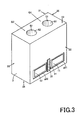
- Fig. 3 is a perspective view of a dielectric device according to another embodiment of the present invention;
- Fig. 4 is a perspective view of the dielectric device shown in Fig. 3, as seen from a rear side thereof,
- Fig. 5 is a cross-sectional view taken along
line 5·5 in Fig. 3; - Fig. 6 is a cross-sectional view taken along line 6-6 in Fig. 5;
- Fig. 7 is a diagram showing use (i.e., a mounted state to a circuit board) of the dielectric devices shown in Figs. 1 to 6;
- Fig. 8 is a diagram showing a dielectric device according to still another embodiment of the present invention and a process of mounting the dielectric device to a circuit board;
- Fig. 9 is a diagram showing a mounted state subsequent to Fig. 8;
- Fig. 10 is a diagram showing a dielectric device according to still another embodiment of the present invention and a process of mounting the dielectric device to a circuit board;
- Fig. 11 is a diagram showing a mounted state subsequent to Fig. 10;
- Fig. 12 is a perspective view of a dielectric device with three resonator units;
- Fig. 13 is a perspective view of the dielectric device shown in Fig. 12, as seen from a rear side thereof;
- Fig. 14 is a cross-sectional view of the dielectric device shown in Figs. 12 and 13;
- Fig. 15 is a cross-sectional view taken along line 15-15 in Fig. 14;
- Fig. 16 is a diagram showing frequency attenuation characteristics of dielectric devices having the basic structure shown in Figs. 12 to 15;
- Fig. 17 is a perspective view of a dielectric device according to still another embodiment of the present invention;
- Fig. 18 is a perspective view of the dielectric device shown in Fig. 17, as seen from a rear side thereof;
- Fig. 19 is a cross-sectional view taken along line 19-19 in Fig. 18;
- Fig. 20 is a perspective view of a dielectric device according to still another embodiment of the present invention;
- Fig. 21 is a perspective view of a duplexer according to still another embodiment of the present invention;
- Fig. 22 is a perspective view of the duplexer shown in Fig. 21, as seen from a rear side thereof, and
- Fig. 23 is a cross-sectional view taken along line 23-23 in Fig. 22.
- Referring to Figs. 1 and 2, a dielectric device according to a first embodiment of the present invention includes a
dielectric substrate 1 and two resonator units Q1, Q2. Thedielectric substrate 1 is formed from a well-known dielectric ceramic to have a generally hexahedral shape with first to sixthexternal surfaces 21 to 26. Typically, anexternal conductor film 3 may be formed by baking, plating or the like to contain copper, silver or the like as a main component. - The resonator unit Q1 includes a
hole 51. Thehole 51 opens on the third andfourth surfaces internal conductor 81 therein. Theinternal conductor 81 connects with theexternal conductor film 3 at one end opening on the fourthexternal surface 24. Alternatively, theinternal conductor 81 may be formed by filling a part or the whole of thehole 51. - The resonator unit Q2, which has substantially the same configuration as the resonator unit Q1, includes a
hole 52. Since the resonator unit Q2 has the same configuration as the resonator unit Q1, the explanation about the effects and advantages of the resonator unit Q1 is applicable to the resonator unit Q2. Concerning the effects of the whole dielectric device, furthermore, the coupling between the resonator units Q1, Q2 should be considered. - The second
external surface 22 of thedielectric substrate 1 is provided with first andsecond terminals first terminal 11 is opposed to thehole 51 and electrically isolated from theexternal conductor film 3 by an isolating gap g21. Thesecond terminal 12 is opposed to thehole 52 and electrically isolated from theexternal conductor film 3 by an isolating gap g22. - Between the first and
second terminals internal conductors second terminals intermediate conductor film 31, which is a par of theexternal conductor film 3. - The above configuration has been well known in the art. The first embodiment of the present invention is characterized in that the
intermediate conductor film 31 has an insulatingfilm 91 thereon. The effects and advantages thereof will be described hereinbelow with reference to Figs. 7 to 11. Examples of the insulatingfilm 91 include a glass film, a solder resist film, an organic insulating film, and an inorganic insulating film. These films can be formed by using a simple coating method and therefore are highly suitable for mass production. - Referring to Figs. 3 to 6, a dielectric device according to a second embodiment of the present invention includes a
dielectric substrate 1 and two resonator units Q1, Q2. Thedielectric substrate 1 is formed from a well-known dielectric ceramic to have a generally hexahedral shape with first to sixthexternal surfaces 21 to 26. Typically, anexternal conductor film 3 may be formed by baking, plating or the like to contain copper, silver or the like as a main component. - The resonator unit Q1 includes first and
second holes first hole 41 is provided in thedielectric substrate 1 and extends from the firstexternal surface 21 toward the opposite secondexternal surface 22 with one end opening on the firstexternal surface 21. Thefirst hole 41 has a firstinternal conductor 61 therein. The firstinternal conductor 61 may be formed as an electrode film from the same material and by the same means as theexternal conductor film 3. Alternatively, the firstinternal conductor 61 may be formed by filling a part or the whole of thefirst hole 41. The firstinternal conductor 61 is separated from theexternal conductor film 3 on the firstexternal surface 21 by a gap g11. - The
second hole 51 is also provided in thedielectric substrate 1 and extends from the thirdexternal surface 23 toward the opposite fourthexternal surface 24 with one end opening on the thirdexternal surface 23. The other end of thesecond hole 51 is connected to thefirst hole 41 inside thedielectric substrate 1. - The
second hole 51 has a secondinternal conductor 81 therein. The secondinternal conductor 81 has one end connected to theexternal conductor film 3 on thethird surface 23 and the other end connected to the firstinternal conductor 61. The secondinternal conductor 81 may be formed from the same material and by the same means as the firstinternal conductor 61. Alternatively, the secondinternal conductor 81 may be formed by filling a part or the whole of thesecond hole 51. - In the illustrated embodiment, the
second hole 51 is of a substantially circular shape with an inner diameter D2. Thefirst hole 41 is of a generally rectangular shape, of which an inner diameter D11 along the width direction is larger than an inner diameter D12 along the length direction. The inner diameter D11 along the width direction is larger than the inner diameter D2 of thesecond hole 51. Therefore, thesecond hole 51 is connected to thefirst hole 41 with its inside end within the width of thefirst hole 41. Thefirst hole 41 preferably has rounded corners. Although D11 is larger than D12 in the illustrated embodiment, D12 may be equal to or larger than D11. In the illustrated embodiment, furthermore, thefirst hole 41 extends a distance X1 along the depth direction beyond a junction with the second hole 51 (see Fig. 5). - The resonator unit Q2, which has substantially the same configuration as the resonator unit Q1, includes first and
second holes - Whether the coupling between the resonator units Q1, Q2 is a capacitive coupling or an inductive coupling depends on the relative relationship between two capacitances: one being a capacitance formed between the
internal conductor 61 of thefirst hole 41 and theinternal conductor 62 of thefirst hole 42; the other being a capacitance formed between theexternal conductor film 3 and theinternal conductors first holes - The second
external surface 22 of thedielectric substrate 1 is provided with first andsecond terminals first terminal 11 is opposed to thefirst hole 41 and electrically isolated from theexternal conductor film 3 by an isolating gap g21. Thesecond terminal 12 is opposed to thefirst hole 42 and electrically isolated from theexternal conductor film 3 by an isolating gap g22. - Between the first and
second terminals internal conductors first holes second terminals internal conductors first holes second terminals internal conductors first holes second terminals intermediate conductor film 31, which is a part of theexternal conductor film 3. - In the resonator unit Q1, as described above, the
first hole 41 extends from the firstexternal surface 21 toward the opposite secondexternal surface 22 with one end opening on the firstexternal surface 21. Thesecond hole 51 extends from the thirdexternal surface 23 toward the opposite fourthexternal surface 24 with one end opening on the thirdexternal surface 23. The other end of thesecond hole 51 is connected to thefirst hole 41 inside thedielectric substrate 1. - In this hole configuration, since the first
internal conductor 61 and the secondinternal conductor 81 are connected to each other, as described above, thefirst hole 41 and thesecond hole 51 constitute one electric circuit. The firstinternal conductor 61 is opposed to theexternal conductor film 3 on the second, fourth to sixthexternal surfaces internal conductor 61 and theexternal conductor film 3. - Since the first
internal conductor 61 of thefirst hole 41 is opposed to theexternal conductor film 3 across thedielectric substrate 1, as described above, large electrostatic capacitances are formed between the firstinternal conductor 61 and the external conductor film 3 (see Figs. 5 and 6). Therefore, the dielectric device according to the second embodiment of the present invention resonates at a frequency that is less than the electrical length of thedielectric substrate 1 having a length L1 along the axial direction of thesecond hole 51. In other words, miniaturization and height reduction can be achieved by shortening the length L1 of thedielectric substrate 1 in order to obtain a desired resonant frequency. - Next, a specific example will be given to describe miniaturization and height reduction of the dielectric device according to the second embodiment. The specific example was prepared in accordance with the configuration of the dielectric device illustrated in Figs. 3 to 6. The
dielectric substrate 1 was formed from a dielectric material of a relative dielectric constant ε r = 92 into a generally rectangular parallelepiped shape. The external dimensions of thedielectric substrate 1 were such that the plane area of the thirdexternal surface 23 was (2 mm x 2 mm) and the length L1 was 2.5 mm. The inner diameter D2 of thesecond hole 51 was 0.5 mm, and the inner diameter D11 of thefirst hole 41 was 1 mm. - When measured in a loosely coupled state, this dielectric device had a resonant frequency of 2.02 GHz. This means that the dielectric device according to the second embodiment can shorten the length L1 by about 30% as compared with conventional quarter-wavelength resonators with a resonant frequency of 2.02 GHz in which the length L1 needs to be about 3.5 to 4 mm.
- The above configuration and its effects and advantages have been well known as disclosed in
Japanese Patent No. 3329450 intermediate conductor film 31 has an insulatingfilm 91 thereon. - With the insulating
film 91 on theintermediate conductor film 31, as in the first and second embodiments illustrated in Figs. 1 to 6, although most of theexternal conductor film 3 connects with an earthingconductor 102 on acircuit board 101 through asolder 105 or the like when adielectric device 100 is mounted on thecircuit board 101 with the first andsecond terminals circuit board 101, the insulatingfilm 91 ensures separation of theintermediate conductor film 31 from the earthingconductor 102, as shown in Fig. 7. Therefore, filter characteristics such as pass band width can be adjusted by generating a sharp attenuation pole at a high-frequency side while hardly shifting a low-frequency attenuation pole. It is also possible to adjust an attenuation pole frequency by changing the relative length of the insulatingfilm 91 to the first andsecond terminals - As described above, examples of the insulating
film 91 include a glass film, a solder resist film, an organic insulating film, and an inorganic insulating film. These films can be formed by using a simple coating method and therefore are highly suitable for mass production. It should be noted that the first andsecond terminals conductors circuit board 101 through thesolder 105. - As understood from the foregoing description, the basic technical idea of the present invention is to separate the
intermediate conductor film 31, which is a part of theexternal conductor film 3, from the earthingconductor 102. Accordingly, it may be embodied in a variety of ways as long as having the above function, for example, as shown in Figs. 8 and 9 as a third embodiment. - Referring first to Fig. 8, the
intermediate conductor film 31 is thinner than the first andsecond terminals external conductor film 3 connects with the earthingconductor 102 on thecircuit board 101 through the solder or the like when thedielectric device 100 is mounted with the first andsecond terminals circuit board 101, the difference in surface level between theintermediate conductor film 31 and the first andsecond terminals intermediate conductor film 31 from the earthingconductor 102, as shown in Fig. 9. Therefore, a sharp attenuation pole can be generated at a high-frequency side while hardly shifting a low-frequency attenuation pole. It is also possible to adjust an attenuation pole frequency. - The above function can also be achieved by adapting the circuit board, for example, as shown in Figs. 10 and 11 as still another embodiment. Referring to Fig. 10, a portion of the
circuit board 101, which is intended to face theintermediate conductor film 3 when thedielectric device 100 is mounted on thecircuit board 101, is covered with an insulatingfilm 91. - With the above configuration, although most of the
external conductor film 3 connects with the earthingconductor 102 on thecircuit board 101 through thesolder 105 or the like when the dielectric device is mounted with the first andsecond terminals circuit board 101, the insulatingfilm 91 ensures separation of theintermediate conductor film 31 from the earthingconductor 102. Therefore, filter characteristics such as pass band width can be adjusted by generating a sharp attenuation pole at a high-frequency side while hardly shifting a low-frequency attenuation pole. It is also possible to adjust an attenuation pole frequency by changing the relative length of the insulatingfilm 91 to the first andsecond terminals - Fig. 12 is a perspective view of a dielectric device with three resonator units Q1, Q2, Q3; Fig. 13 is a perspective view of the dielectric device shown in Fig. 12, as seen from a rear side thereof; Fig. 14 is a cross-sectional view taken along line 14-14 in Fig. 12; and Fig. 15 is a cross-sectional view taken along line 15-15 in Fig. 14.
- The resonator units Q1, Q2, Q3 share a
dielectric substrate 1 and are integrated via thedielectric substrate 1. - The resonator unit Q1 includes first and
second holes second holes second holes first holes 41 to 43 and thesecond holes 51 to 53 may be configured and related to each other as described above. - The
first terminal 11 is provided on the secondexternal surface 22, opposed to thefirst hole 41, and electrically isolated from theexternal conductor film 3 by the isolating gap g21. Thesecond terminal 12 is provided on the secondexternal surface 22, opposed to thefirst hole 43, and electrically isolated from theexternal conductor film 3 by the isolating gap g22. Between the first andsecond terminals intermediate conductor film 31, which is a part of theexternal conductor film 3. - With the insulating
film 91 on theintermediate conductor film 31, although most of theexternal conductor film 3 connects with the earthingconductor 102 on thecircuit board 101 through thesolder 105 or the like when the dielectric device is mounted with the first andsecond terminals circuit board 101, the insulatingfilm 91 ensures separation of theintermediate conductor film 31 from the earthingconductor 102, as shown in Fig. 7. Therefore, filter characteristics such as pass band width can be adjusted by generating a sharp attenuation pole at a high-frequency side while hardly shifting a low-frequency attenuation pole. It is also possible to adjust an attenuation pole frequency by changing the relative length of the insulatingfilm 91 to the first andsecond terminals - Next, the effects and advantages of the dielectric device according to one embodiment of the present invention will be described with reference to data shown in Fig. 16. Fig. 16 shows frequency attenuation characteristics of dielectric devices (or dielectric filter) having the basic structure shown in Figs. 12 to 15. In Fig. 16, the curve L12 represents characteristics of a dielectric device provided with the insulating
film 91, and the curve L22 represents characteristics of a dielectric device not provided with the insulatingfilm 91. - Referring to Fig. 16, in case of the dielectric device not provided with the insulating
film 91, the high-frequency attenuation pole was generated in the vicinity of 5,400 MHz as shown by the curve L22. In case of the dielectric device provided with the insulatingfilm 91, on the other hand, the high-frequency attenuation pole was generated in the vicinity of 2,700 MHz as shown by the curve L12, which means that the insulatingfilm 91 shifted the high-frequency attenuation pole from a place P2 to a lower frequency place P1. - Thus, excellent pass attenuation characteristics can be obtained by generating a high-frequency attenuation pole at a place closer to the pass band without changing a low-frequency attenuation pole in the pass band. Here, the frequency place of the high-frequency attenuation pole may shift closer to the low-frequency side depending on the length, width and material of the insulating
film 91. - Fig. 17 is a perspective view of a dielectric device with three resonator units Q1, Q2, Q3 according to still another embodiment of the present invention; Fig. 18 is a perspective view of the dielectric device as seen from a rear side thereof; and Fig. 19 is a cross-sectional view taken along line 19-19 in Fig. 18. In the illustrated dielectric device, the first
internal conductors external conductor film 3 on the firstexternal surface 21. The thirdexternal surface 23, on which thesecond holes internal conductors external conductor film 3. Therefore, the plane area of the thirdexternal surface 23 may be exploited to form a conductive pattern as a circuit element, thereby adjusting a coupling capacitance between the resonator units Q1, Q2, Q3 to obtain desired filter characteristics. - Referring to Fig. 20, the
first terminal 11 is disposed adjacent the thirdexternal surface 23, which is an open end surface, and opposed to thesecond hole 51 while being electrically isolated from theexternal conductor film 3 by the insulatinggap 21. Thesecond terminal 12 is also disposed adjacent the thirdexternal surface 23 and opposed to thesecond hole 53 while being electrically isolated from theexternal conductor film 3 by the insulatinggap 22. Between the first andsecond terminals intermediate conductor film 31, which is a part of theexternal conductor film 3. - Also in this embodiment, the
intermediate conductor film 31 has an insulatingfilm 91 thereon. When the dielectric device is mounted with the first andsecond terminals film 91 to the first andsecond terminals film 91. - The circuit element to be formed on the third external surface (or open end surface) 23 may have a variety of patterns, as exemplified in Fig. 20. Fig. 20 is a perspective view of a dielectric device according to still another embodiment of the present invention. In this embodiment,
circuit elements circuit elements - Next, there will be described a duplexer, which is another important application of the dielectric device according to the present invention. Fig. 21 is a perspective view of a duplexer according to still another embodiment of the present invention; Fig. 22 is a perspective view of the duplexer shown in Fig. 21, as seen from a rear side thereof; and Fig. 23 is a cross-sectional view taken along line 23-23 in Fig. 22. The illustrated duplexer includes six resonator units Q1 to Q6. The resonator units Q1 to Q6 share the
dielectric substrate 1 and are integrated via thedielectric substrate 1. Of thedielectric substrate 1, most of the external surfaces, except the thirdexternal surface 23, are covered with theexternal conductor film 3. - Among the resonator units Q1 to Q6, the resonator unit Q1 includes a combination of first and
second holes second holes second holes second holes second holes second holes - The first hole (41 to 46) and the second hole (51 to 56) may be configured and related to each other as described with reference to Figs. 1 to 15. The first hole (41 to 46) has the first internal conductor (61 to 66), and the second hole (51 to 56) has the second internal conductor (81 to 86).
- Since the duplexer is used as an antenna duplexer, either of two resonator unit groups (the resonator units Q1 to Q3 or the resonator units Q4 to Q6) is used for a transmitter, while the other group is used for a receiver. Since the transmit frequency and the receive frequency are different from each other, the resonance characteristics of the resonator units Q1 to Q3 and the resonance characteristics of the resonator units Q4 to Q6 also should be different from each other.
- The resonator units Q1 to Q3 may be coupled together via a conductive pattern (or a circuit element). Here, a
first terminal 11 is provided on the secondexternal surface 22 and coupled with thefirst hole 41 of the resonator unit Q1 via the dielectric layer of thedielectric substrate 1. - The resonator units Q4 to Q6 may also be coupled together via a conductive pattern (or a circuit element). Here, a
third terminal 13 is provided on the secondexternal surface 22 and coupled with thefirst hole 46 of the resonator unit Q6 via the dielectric layer of thedielectric substrate 1. Such capacitive coupling has been described in detail hereinabove. - Furthermore, a
second terminal 12 for connection with an antenna is provided on the secondexternal surface 22 and coupled with thefirst holes - The first to
third terminals 11 to 13 on the secondexternal surface 22 are electrically isolated from theexternal conductor film 3 by insulating gaps g21 to g23. The first tothird terminals 11 to 13 ensure face-to-face attachment to a mounting board. - Between the first and
second terminals intermediate conductor film 31, which is a part of theexternal conductor film 3. Between the second andthird terminals intermediate conductor film 32, which is also a part of theexternal conductor film 3. - Also in this embodiment, the
intermediate conductor film 31 has an insulatingfilm 91 thereon, and theintermediate conductor film 32 has an insulatingfilm 92 thereon. When the dielectric device is mounted with the first tothird terminals 11 to 13 facing a circuit board, accordingly, filter characteristics such as pass band width can be adjusted by generating an attenuation pole at a desired frequency place in the vicinity of the pass band while hardly shifting a low-frequency attenuation pole. It is also possible to adjust an attenuation pole frequency by changing the relative length of the insulatingfilms third terminals 11 to 13 and the width, thickness and material of the insulatingfilms - Although not shown in the drawings, it will be appreciated the configurations described with reference to the dielectric filters shown in Figs. 1 to 20 may also be adopted for a duplexer.
- While the present invention has been particularly shown and described with reference to embodiments thereof, it will be understood by those skilled in the art that various changes in form and detail may be made therein without departing from the spirit, scope and teaching of the invention. For example, the
first holes 41 to 46 of the resonator units Q1 to Q6 do not necessarily need to open on a common external surface. They may open on different external surfaces depending on the locations of the input/output terminals and the convenience of adjustment. If the fourthexternal surface 24 opposite to the thirdexternal surface 23 is not covered with theexternal conductor film 3, there can be obtained a λ/2 dielectric resonator.
Claims (13)
- A dielectric device comprising a dielectric substrate (1), a plurality of resonator units (Q1, Q2), and first and second terminals (11, 12),
said dielectric substrate (1) having an external conductor film (3) thereon,
each of said resonator units (Q1, Q2) having a hole (51, 52) and an internal conductor (81,82) provided inside said hole (51, 52) and connecting with said external conductor film (3),
said first terminal (11) being provided on said dielectric substrate (1) and electrically coupled with at least one of said resonator units (Q1, Q2),
said second terminal (12) being provided on said dielectric substrate (1) and electrically coupled with at least another of said resonator units (Q1, Q2),
an intermediate conductor film (31), which is a part of said external conductor film (3), being provided between said first and second terminals (11, 12),
said intermediate conductor film (31) having an insulating film (91) thereon. - A dielectric device comprising a dielectric substrate (1), a plurality of resonator units (Q1, Q2), and first and second terminals (11, 12),
said dielectric substrate (1) having an external conductor film (3) thereon,
each of said resonator units (Q1, Q2) having first and second holes (41, 51), (42, 52),
said first hole (41, 51) being provided in said dielectric substrate (1), opening on a first external surface (21) of said dielectric substrate (1), extending toward a second external surface (22) of said dielectric substrate (1) opposite to said first external surface (21), and having a first internal conductor (61, 62) therein,
said second hole (51, 52) being provided in said dielectric substrate (1), opening on a third external surface (23) of said dielectric substrate (1) not opposite to said first external surface (21), connecting with said first hole (41, 42) inside said dielectric substrate (1), and having a second internal conductor (81, 82) therein,
said second internal conductor (81, 82) connecting with said first internal conductor (61, 62) inside said dielectric substrate (1),
said first terminal (11) being provided on said dielectric substrate (1) and electrically coupled with at least one of said resonator units,
said second terminal (12) being provided on said dielectric substrate (1) and electrically coupled with at least another of said resonator units (Q1, Q2),
an intermediate conductor film (31), which is a part of said external conductor film (3), being provided between said first and second terminals (11,12),
said intermediate conductor film (31) having an insulating film (91) thereon. - The dielectric device of any one of claims 1 and 2, wherein said insulating film is a glass film, a solder resist film, an organic insulating film, or an inorganic insulating film.
- A dielectric device comprising a dielectric substrate (1), a plurality of resonator units (Q1, Q2), and first and second terminals (11, 12),
said dielectric substrate (1) having an external conductor film (3) thereon,
each of said resonator units (Q1, Q2) having first and second holes (41, 51), (42, 52),
said first hole being provided in said dielectric substrate (1), opening on a first external surface of said dielectric substrate, extending toward a second external surface (21) of said dielectric substrate (1) opposite to said first external surface (21), and having a first internal conductor (61, 62) therein,
said second hole (51, 52) being provided in said dielectric substrate (1), opening on a third external surface (23) of said dielectric substrate (1) not opposite to said first external surface (21), connecting with said first hole (41,42) inside said dielectric substrate (1), and having a second internal conductor (81,82) therein,
said second internal conductor (81, 82) connecting with said first internal conductor (61, 62) inside said dielectric substrate (1),
said first terminal (11) being provided on said dielectric substrate (1) and electrically coupled with at least one of said resonator units (Q1, Q2),
said second terminal (12) being provided en said dielectric substrate (1) and electrically coupled with at least another of said resonator units (Q1, Q2),
an intermediate conductor film (31), which is a part of said external conductor film (3), being provided between said first and second terminals (11, 12),
said intermediate conductor film (31) being thinner than said first and second terminals (11, 12) to have a difference in surface level. - The dielectric device of any one of claims 1, 2 and 4, which is a dielectric filter or a duplexer.
- An electronic device comprising the dielectric device of claim 1 and a circuit board having said dielectric device mounted thereon.
- An electronic device comprising the dielectric device of claim 2 and a circuit board having said dielectric device mounted thereon.
- An electronic device comprising the dielectric device of claim 3 and a circuit board having said dielectric device mounted thereon.
- An electronic device comprising the dielectric device of claim 4 and a circuit board having said dielectric device mounted thereon.
- An electronic device comprising the dielectric device of claim 5 and a circuit board having said dielectric device mounted thereon.
- An electronic device comprising a dielectric device (100) and a circuit board (101),
said dielectric device (100) including a dielectric substrate (1), a plurality of resonator units (Q1, Q2), and first and second terminals (11, 12),
said dielectric substrate (1) having an external conductor film (3) thereon,
each of said resonator units (Q1, Q2) having first and second holes (41, 51), (42, 52),
said first hole (41, 51) being provided in said dielectric substrate (1), opening on a first external surface (21) of said dielectric substrate (1), extending toward a second external surface (22) of said dielectric substrate opposite to said first external surface (21), and having a first internal conductor (61,62) therein,
said second hole (51, 52) being provided in said dielectric substrate (1), opening on a third external surface (23) of said dielectric substrate (1) not opposite to said first external surface (21), connecting with said first hole (41, 42) inside said dielectric substrate (1), and having a second internal conductor (81, 82) therein,
said second internal conductor (81, 82) connecting with said first internal conductor (61, 62) inside said dielectric substrate (1),
said first terminal (11) being provided on said dielectric substrate (1) and electrically coupled with at least one of said resonator units (Q1, Q2),
said second terminal (12) being provided on said dielectric substrate (1) and electrically coupled with at least another of said resonator units (Q1, Q2),
an intermediate conductor film (31), which is a part of said external conductor film (3), being provided between said first and second terminals (11, 12),
said circuit board (101) having said dielectric device (100) mounted thereon, said circuit board (101) being covered with an insulating film (91) at a portion facing said intermediate conductor film (31) . - An electronic device of claim 11, wherein said insulating film is a glass film, a solder resist film, an organic insulating film, or an inorganic insulating film.
- The electronic device of claim 11, wherein the dielectric devices is a dielectric filter or a duplexer.
Applications Claiming Priority (1)
| Application Number | Priority Date | Filing Date | Title |
|---|---|---|---|
| JP2005299173A JP4148423B2 (en) | 2005-10-13 | 2005-10-13 | Dielectric device |
Publications (2)
| Publication Number | Publication Date |
|---|---|
| EP1777774A1 true EP1777774A1 (en) | 2007-04-25 |
| EP1777774B1 EP1777774B1 (en) | 2010-08-18 |
Family
ID=37606924
Family Applications (1)
| Application Number | Title | Priority Date | Filing Date |
|---|---|---|---|
| EP06255290A Expired - Fee Related EP1777774B1 (en) | 2005-10-13 | 2006-10-13 | Dielectric device |
Country Status (5)
| Country | Link |
|---|---|
| US (1) | US7535318B2 (en) |
| EP (1) | EP1777774B1 (en) |
| JP (1) | JP4148423B2 (en) |
| CN (2) | CN102394326A (en) |
| DE (1) | DE602006016210D1 (en) |
Families Citing this family (5)
| Publication number | Priority date | Publication date | Assignee | Title |
|---|---|---|---|---|
| JP2009147058A (en) * | 2007-12-13 | 2009-07-02 | Panasonic Corp | Impedance matching filter and mounting board |
| TWI635650B (en) * | 2016-10-13 | 2018-09-11 | 太盟光電科技股份有限公司 | Filter structure |
| US10312563B2 (en) * | 2016-11-08 | 2019-06-04 | LGS Innovations LLC | Ceramic filter with differential conductivity |
| CN110088977B (en) * | 2016-12-16 | 2020-07-28 | 华为技术有限公司 | Dielectric resonator, dielectric filter using same, transceiver and base station |
| CN113036325B (en) * | 2021-01-26 | 2022-08-12 | 嘉兴佳利电子有限公司 | Dielectric filter |
Citations (3)
| Publication number | Priority date | Publication date | Assignee | Title |
|---|---|---|---|---|
| US5045824A (en) * | 1990-09-04 | 1991-09-03 | Motorola, Inc. | Dielectric filter construction |
| US5760666A (en) * | 1992-09-07 | 1998-06-02 | Murata Manufacturing Co., Ltd. | Dielectric resonant component with resist film on the mount substrate |
| EP1298758A2 (en) * | 2001-09-28 | 2003-04-02 | TDK Corporation | Dielectric device |
Family Cites Families (19)
| Publication number | Priority date | Publication date | Assignee | Title |
|---|---|---|---|---|
| JPH0597105A (en) | 1991-10-07 | 1993-04-20 | Youka Tekko Kk | Spherical object packaging method |
| US5218329A (en) * | 1992-03-25 | 1993-06-08 | Motorola, Inc. | Low profile ceramic filter with self aligning shield |
| JPH0779104A (en) * | 1993-09-06 | 1995-03-20 | Murata Mfg Co Ltd | Dielectric resonator |
| JPH0832314A (en) | 1994-07-20 | 1996-02-02 | Murata Mfg Co Ltd | Dielectric filter |
| JP2836536B2 (en) * | 1995-08-25 | 1998-12-14 | 松下電器産業株式会社 | Dielectric filter and package mounting the same |
| JP3023949B2 (en) | 1995-12-12 | 2000-03-21 | 株式会社村田製作所 | Dielectric filter |
| JP3389819B2 (en) | 1996-06-10 | 2003-03-24 | 株式会社村田製作所 | Dielectric waveguide resonator |
| JP3155721B2 (en) | 1996-12-28 | 2001-04-16 | 東光株式会社 | Dielectric filter |
| JP3176859B2 (en) | 1996-12-28 | 2001-06-18 | 東光株式会社 | Dielectric filter |
| JPH10308608A (en) | 1997-03-03 | 1998-11-17 | Ngk Spark Plug Co Ltd | Dielectric duplexer |
| JP3752823B2 (en) * | 1998-03-19 | 2006-03-08 | 株式会社村田製作所 | Dielectric filter, dielectric duplexer, dielectric filter mounting structure, dielectric duplexer mounting structure, and communication device |
| JP2000101306A (en) | 1998-09-25 | 2000-04-07 | Ngk Spark Plug Co Ltd | Dielectric filter |
| KR100286807B1 (en) | 1998-12-21 | 2001-04-16 | 이형도 | Integral Dielectric Filter |
| JP2001094304A (en) * | 1999-09-17 | 2001-04-06 | Tdk Corp | Dielectric filter and its manufacture |
| JP3613156B2 (en) * | 2000-01-18 | 2005-01-26 | 株式会社村田製作所 | Dielectric filter, antenna duplexer, and communication device |
| US6570473B2 (en) * | 2000-08-30 | 2003-05-27 | Tkd Corporation | Band pass filter |
| JP2002158512A (en) * | 2000-09-08 | 2002-05-31 | Murata Mfg Co Ltd | Dielectric resonator, dielectric filter, dielectric duplexer and communications equipment |
| JP3317404B1 (en) * | 2001-07-25 | 2002-08-26 | ティーディーケイ株式会社 | Dielectric device |
| JP2003298310A (en) * | 2002-03-29 | 2003-10-17 | Ngk Spark Plug Co Ltd | Dielectric filter |
-
2005
- 2005-10-13 JP JP2005299173A patent/JP4148423B2/en not_active Expired - Fee Related
-
2006
- 2006-10-12 US US11/546,252 patent/US7535318B2/en not_active Expired - Fee Related
- 2006-10-13 DE DE602006016210T patent/DE602006016210D1/en active Active
- 2006-10-13 EP EP06255290A patent/EP1777774B1/en not_active Expired - Fee Related
- 2006-10-13 CN CN2011101922648A patent/CN102394326A/en active Pending
- 2006-10-13 CN CN2006101373495A patent/CN1949588B/en not_active Expired - Fee Related
Patent Citations (3)
| Publication number | Priority date | Publication date | Assignee | Title |
|---|---|---|---|---|
| US5045824A (en) * | 1990-09-04 | 1991-09-03 | Motorola, Inc. | Dielectric filter construction |
| US5760666A (en) * | 1992-09-07 | 1998-06-02 | Murata Manufacturing Co., Ltd. | Dielectric resonant component with resist film on the mount substrate |
| EP1298758A2 (en) * | 2001-09-28 | 2003-04-02 | TDK Corporation | Dielectric device |
Also Published As
| Publication number | Publication date |
|---|---|
| CN102394326A (en) | 2012-03-28 |
| JP2007110426A (en) | 2007-04-26 |
| EP1777774B1 (en) | 2010-08-18 |
| CN1949588A (en) | 2007-04-18 |
| US20070085628A1 (en) | 2007-04-19 |
| DE602006016210D1 (en) | 2010-09-30 |
| JP4148423B2 (en) | 2008-09-10 |
| CN1949588B (en) | 2013-03-13 |
| US7535318B2 (en) | 2009-05-19 |
Similar Documents
| Publication | Publication Date | Title |
|---|---|---|
| JP6522244B2 (en) | Cavity type radio frequency filter with cross coupling notch structure | |
| EP0997973B1 (en) | Antenna with filter and radio apparatus using this antenna | |
| US8283990B2 (en) | Signal transmission communication unit and coupler | |
| US6737943B2 (en) | Dielectric device with partially closed hole | |
| US7239214B2 (en) | Two-port non-reciprocal circuit device and communication apparatus | |
| KR101727066B1 (en) | Wireless Frequency Filter | |
| US7432786B2 (en) | High frequency filter | |
| EP1764858B1 (en) | Dielectric device | |
| EP1777774B1 (en) | Dielectric device | |
| US6727784B2 (en) | Dielectric device | |
| JP5762070B2 (en) | Bandpass filter | |
| JP6287031B2 (en) | Dielectric resonant component | |
| JP2020072450A (en) | Dielectric resonance component | |
| US6150906A (en) | HF filter using resonators having convex-concave structure | |
| US9634367B2 (en) | Filter | |
| KR100258788B1 (en) | Microwave band pass filters made with an half-cut coaxial resonators | |
| JPH0832307A (en) | Dielectric device | |
| KR100199330B1 (en) | Dielectric filter | |
| JP2000299601A (en) | Dielectric device and production thereof | |
| JP2010239414A (en) | Dielectric resonance component and mounting structure using the same | |
| JP2003110318A (en) | Dielectric device | |
| JP2003258505A (en) | Dielectric apparatus | |
| JP2007096773A (en) | Dielectric device | |
| JPH04188903A (en) | Dielectric band blocking filter | |
| JP2007124573A (en) | Dielectric device |
Legal Events
| Date | Code | Title | Description |
|---|---|---|---|
| PUAI | Public reference made under article 153(3) epc to a published international application that has entered the european phase |
Free format text: ORIGINAL CODE: 0009012 |
|
| AK | Designated contracting states |
Kind code of ref document: A1 Designated state(s): AT BE BG CH CY CZ DE DK EE ES FI FR GB GR HU IE IS IT LI LT LU LV MC NL PL PT RO SE SI SK TR |
|
| AX | Request for extension of the european patent |
Extension state: AL BA HR MK YU |
|
| 17P | Request for examination filed |
Effective date: 20071025 |
|
| AKX | Designation fees paid |
Designated state(s): DE FI FR GB SE |
|
| 17Q | First examination report despatched |
Effective date: 20080228 |
|
| GRAP | Despatch of communication of intention to grant a patent |
Free format text: ORIGINAL CODE: EPIDOSNIGR1 |
|
| GRAS | Grant fee paid |
Free format text: ORIGINAL CODE: EPIDOSNIGR3 |
|
| GRAA | (expected) grant |
Free format text: ORIGINAL CODE: 0009210 |
|
| AK | Designated contracting states |
Kind code of ref document: B1 Designated state(s): DE FI FR GB SE |
|
| REG | Reference to a national code |
Ref country code: GB Ref legal event code: FG4D |
|
| REF | Corresponds to: |
Ref document number: 602006016210 Country of ref document: DE Date of ref document: 20100930 Kind code of ref document: P |
|
| PG25 | Lapsed in a contracting state [announced via postgrant information from national office to epo] |
Ref country code: SE Free format text: LAPSE BECAUSE OF FAILURE TO SUBMIT A TRANSLATION OF THE DESCRIPTION OR TO PAY THE FEE WITHIN THE PRESCRIBED TIME-LIMIT Effective date: 20100818 |
|
| PLBE | No opposition filed within time limit |
Free format text: ORIGINAL CODE: 0009261 |
|
| STAA | Information on the status of an ep patent application or granted ep patent |
Free format text: STATUS: NO OPPOSITION FILED WITHIN TIME LIMIT |
|
| 26N | No opposition filed |
Effective date: 20110519 |
|
| GBPC | Gb: european patent ceased through non-payment of renewal fee |
Effective date: 20101118 |
|
| PG25 | Lapsed in a contracting state [announced via postgrant information from national office to epo] |
Ref country code: FR Free format text: LAPSE BECAUSE OF NON-PAYMENT OF DUE FEES Effective date: 20101102 |
|
| REG | Reference to a national code |
Ref country code: FR Ref legal event code: ST Effective date: 20110630 |
|
| REG | Reference to a national code |
Ref country code: DE Ref legal event code: R097 Ref document number: 602006016210 Country of ref document: DE Effective date: 20110519 |
|
| PG25 | Lapsed in a contracting state [announced via postgrant information from national office to epo] |
Ref country code: GB Free format text: LAPSE BECAUSE OF NON-PAYMENT OF DUE FEES Effective date: 20101118 |
|
| PGFP | Annual fee paid to national office [announced via postgrant information from national office to epo] |
Ref country code: DE Payment date: 20131009 Year of fee payment: 8 |
|
| PGFP | Annual fee paid to national office [announced via postgrant information from national office to epo] |
Ref country code: FI Payment date: 20131010 Year of fee payment: 8 |
|
| REG | Reference to a national code |
Ref country code: DE Ref legal event code: R119 Ref document number: 602006016210 Country of ref document: DE |
|
| PG25 | Lapsed in a contracting state [announced via postgrant information from national office to epo] |
Ref country code: FI Free format text: LAPSE BECAUSE OF NON-PAYMENT OF DUE FEES Effective date: 20141013 Ref country code: DE Free format text: LAPSE BECAUSE OF NON-PAYMENT OF DUE FEES Effective date: 20150501 |