EP1777480A1 - Wärmeübertrager - Google Patents
Wärmeübertrager Download PDFInfo
- Publication number
- EP1777480A1 EP1777480A1 EP06020006A EP06020006A EP1777480A1 EP 1777480 A1 EP1777480 A1 EP 1777480A1 EP 06020006 A EP06020006 A EP 06020006A EP 06020006 A EP06020006 A EP 06020006A EP 1777480 A1 EP1777480 A1 EP 1777480A1
- Authority
- EP
- European Patent Office
- Prior art keywords
- heat exchanger
- connecting pipe
- pipe piece
- housing
- exchanger according
- Prior art date
- Legal status (The legal status is an assumption and is not a legal conclusion. Google has not performed a legal analysis and makes no representation as to the accuracy of the status listed.)
- Granted
Links
Images
Classifications
-
- F—MECHANICAL ENGINEERING; LIGHTING; HEATING; WEAPONS; BLASTING
- F28—HEAT EXCHANGE IN GENERAL
- F28F—DETAILS OF HEAT-EXCHANGE AND HEAT-TRANSFER APPARATUS, OF GENERAL APPLICATION
- F28F27/00—Control arrangements or safety devices specially adapted for heat-exchange or heat-transfer apparatus
- F28F27/02—Control arrangements or safety devices specially adapted for heat-exchange or heat-transfer apparatus for controlling the distribution of heat-exchange media between different channels
-
- B—PERFORMING OPERATIONS; TRANSPORTING
- B60—VEHICLES IN GENERAL
- B60H—ARRANGEMENTS OF HEATING, COOLING, VENTILATING OR OTHER AIR-TREATING DEVICES SPECIALLY ADAPTED FOR PASSENGER OR GOODS SPACES OF VEHICLES
- B60H1/00—Heating, cooling or ventilating devices
- B60H1/00507—Details, e.g. mounting arrangements, desaeration devices
- B60H1/00557—Details of ducts or cables
- B60H1/00571—Details of ducts or cables of liquid ducts, e.g. for coolant liquids or refrigerants
Definitions
- the invention relates to a heat exchanger with a housing, in particular at least one collecting box, on which at least one connecting pipe piece is attached, which has at least one through hole to the housing.
- the object of the invention is to provide a heat exchanger with a housing, in particular at least one collecting box, to which at least one connecting pipe piece is attached, which has at least one through-hole to the housing, whose temperature distribution is adjustable.
- the object is at a heat exchanger with a housing, in particular at least one collecting box, on which an at least connecting pipe piece is attached, which has at least one through hole to the housing, achieved in that in at least one connecting pipe piece at least one Verstellrohrgangs movable Verstellrohrgangs is having at least one Verstell trimgangsloch, which is more or less and / or locally variably by moving the Verstellrohr choirs in the connecting pipe piece to cover with the through hole brought to the passage cross section between the connecting pipe piece and the housing targeted vary or discontinue.
- the pipe sections are preferably in the form of hollow circular cylinders. But it is also possible that the pipe pieces, for example, have a (three- or four-) square cross-section.
- the passage cross section between the connecting pipe piece and the housing can be changed defined defined in a simple manner.
- changes in size and / or position of the passage cross-section are possible.
- a plurality of passage cross sections are provided, and that also varies the number of passage cross sections depending on the respective setting.
- a preferred embodiment of the heat exchanger is characterized in that the pipe pieces have a round cross section and are rotatable relative to each other.
- the heat exchanger is preferably a radiator of an air conditioning system which is operated with a coolant.
- the coolant inlet flow and / or the coolant outlet flow of the heat exchanger can be controlled by simply rotating the Verstellrohr GmbHs in the connecting pipe piece.
- a further preferred embodiment of the heat exchanger is characterized in that at least one Verstell begangsloch is formed by a slot. It is also possible to arrange a plurality of adjustment through holes in a specific pattern, which is coordinated with a further pattern in which a plurality of through holes are arranged. Also, the size or the respective width of the adjustment or through holes may be formed varying.
- a further preferred embodiment of the heat exchanger is characterized in that at least one slot in a helical shape in the connecting pipe piece runs.
- the passage cross section can be varied locally. It is also conceivable that the pitch between the threads of the slot changes, in particular reduced or enlarged.
- a further preferred embodiment of the heat exchanger is characterized in that in the vicinity of at least one connection opening of the connecting pipe piece, a sealing element is arranged in the radial direction between the adjusting pipe piece and the connecting pipe piece.
- a further preferred embodiment of the heat exchanger is characterized in that at least one Verstellrohr choir is displaceable in at least one connecting pipe piece in the axial direction.
- the passage cross section between the connecting pipe piece and the housing can be varied.
- an adaptation of the heat exchanger connections to different mounting locations or installation spaces can be achieved.
- a further preferred embodiment of the heat exchanger is characterized in that the housing comprises at least one collecting box, on which at least one connecting pipe piece is attached.
- the connecting pipe piece is preferably an inlet pipe or a drain pipe of the heat exchanger.
- both the inlet pipe and the drain pipe are equipped with a Verstellrohr choir described above.
- a further preferred embodiment of the heat exchanger is characterized in that the heat exchanger comprises a radiator block of an air conditioner. Due to the controllable design of the connections an additional adjustment is created by the comfort in the interior of a motor vehicle can be significantly increased.
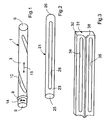
- a Verstellrohr cluster 1 is shown in perspective.
- the Verstellrohr Mos 1 has the shape of a hollow circular cylinder 3 with an open end 5 and a closed end 6. In the vicinity of the open end 5, an O-ring seal 8 is pushed onto the hollow circular cylinder 3.
- the O-ring seal 8 may be fixed in an annular groove on the hollow circular cylinder 3 in the axial direction.
- the hollow circular cylinder 3 is equipped with a helical, helical or spiral-shaped slot 10.
- the slot 10 allows the passage of a medium through the hollow circular cylinder 3 from the inside to the outside and vice versa.
- an arrow 14 is indicated that the hollow circular cylinder 3 and the Verstellrohr Cluster 1 is rotatable in the installed state in the circumferential direction.
- a double arrow 15 is indicated that the Verstellrohr brainstorm 1 or the hollow circular cylinder 3 in the installed state is also displaced in the axial direction.
- a connecting pipe piece 21 is shown in perspective.
- the connecting pipe piece 21 forms the inlet connection of a radiator of an air conditioner.
- the connecting pipe piece 21 is formed by a hollow circular cylinder 23 which has an open end 25 and a closed end 26.
- the open end 25 forms a connection opening, in particular an inlet opening, for a coolant.
- the hollow circular cylinder 23 is equipped with a longitudinal slot 28 extending in the longitudinal direction. The slot 28 allows the passage of coolant.
- a coolant collection box 31 is shown in perspective.
- the coolant collection box 31 essentially has the shape of a cuboid 32, which has two elongated holes 34 and 35 arranged parallel to one another in the longitudinal direction.
- the elongated holes 34 and 35 allow the passage of coolant.
- a plurality of elongated holes may also be provided in the coolant collecting box 31.
- a shorter slot (or a plurality of shorter slots) may be recessed in the coolant collecting box.
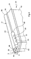
- the heat exchanger 41 is the radiator of an air conditioning system of a motor vehicle.
- the heat exchanger 41 comprises a tube block 43, which in a conventional manner consists of a larger number of tubes, in particular flat tubes, which run parallel to one another. Usually corrugated fins are provided between the tubes to improve the heat transfer to the air to be heated.
- the tube block 43 is acted upon at its broad side with an air flow substantially vertically and flows through it.
- the flat tubes open at one end in the coolant collection box 31, which is also referred to as the upper coolant box. At the other end, the flat tubes open into another (not shown) coolant collection box, which is also referred to as the lower coolant collection box.
- the connecting pipe piece 21 is attached to the upper coolant collecting box 31 so that the long hole in the hollow circular cylinder 3 congruent is disposed above the slot of the coolant collecting box 31.
- Verstellrohr Mos 1 is added in the hollow circular cylinder 23 .
- an arrow 44 is indicated that the Verstellrohrconf 1 in the connecting pipe piece 21 is rotatable.
- a double arrow 46 is indicated that the Verstellrohr Mos 1 in the axial direction in the connecting pipe piece 21 is displaceable.
- the connecting pipe piece 51 Adjacent to the connecting pipe piece 21, another connecting pipe piece 51 is attached to the upper collecting box 31.
- the connecting pipe piece 51 has the shape of a hollow circular cylinder 53, which in the presently illustrated embodiment is approximately half as long as the hollow circular cylinder 23. However, the position of the tap for the return may be variable.
- the hollow circular cylinder 53 has an open end 55 and a closed end 56.
- the open end 55 of the hollow circular cylinder 53 represents a drain opening of the heat exchanger 41, through which the coolant exits.
- a dashed longitudinal slot 58 is indicated that the interior of the hollow circular cylinder 53 is in communication with the interior of the upper header tank 31.
- the two connecting pipe pieces 51 and 21 are preferably fixed to the upper collecting box 31 by a solder joint.
Landscapes
- Engineering & Computer Science (AREA)
- Physics & Mathematics (AREA)
- Thermal Sciences (AREA)
- Mechanical Engineering (AREA)
- General Engineering & Computer Science (AREA)
- Heat-Exchange Devices With Radiators And Conduit Assemblies (AREA)
Abstract
Description
- Die Erfindung betrifft einen Wärmeübertrager mit einem Gehäuse, insbesondere mindestens einem Sammelkasten, an dem wenigstens ein Anschlussrohrstück angebracht ist, das mindestens ein Durchgangsloch zu dem Gehäuse aufweist.
- Aus der
deutschen Offenlegungsschrift DE 191 49 507 A1 ist ein Wärmetauscher eines Kraftfahrzeugs mit zwei Kühlmittelkästen bekannt, zwischen denen ein Rohrblock angeordnet ist. An einem der Kästen sind ein Zulaufrohr und ein Ablaufrohr angebaut. Die angebauten Rohre weisen wenigstens eine radiale Öffnung auf, die mit einer im Kasten ausgebildeten Seitenöffnung kommuniziert. - Aufgabe der Erfindung ist es, einen Wärmeübertrager mit einem Gehäuse, insbesondere mindestens einem Sammelkasten, an dem wenigstens ein Anschlussrohrstück angebracht ist, das mindestens ein Durchgangsloch zu dem Gehäuse aufweist, zu schaffen, dessen Temperaturverteilung einstellbar ist.
- Die Aufgabe ist bei einem Wärmeübertrager mit einem Gehäuse, insbesondere mindestens einem Sammelkasten, an dem ein wenigstens Anschlussrohrstück angebracht ist, das mindestens ein Durchgangsloch zu dem Gehäuse aufweist, dadurch gelöst, dass in zumindest einem Anschlussrohrstück wenigstens ein zu Verstellzwecken bewegbares Verstellrohrstück aufgenommen ist, das mindestens ein Verstelldurchgangsloch aufweist, das durch Bewegen des Verstellrohrstücks in dem Anschlussrohrstück mehr oder weniger und/oder lokal variabel zur Deckung mit dem Durchgangsloch bringbar ist, um den Durchtrittsquerschnitt zwischen dem Anschlussrohrstück und dem Gehäuse gezielt zu variieren beziehungsweise einzustellen. Die Rohrstücke haben vorzugsweise die Gestalt von hohlen Kreiszylindern. Es ist aber auch möglich, dass die Rohrstücke z.B. einen (drei- bzw. vier-) eckigen Querschnitt aufweisen. Durch eine Relativbewegung des Verstellrohrstücks in dem Anschlussrohrstück kann der Durchtrittsquerschnitt zwischen dem Anschlussrohrstück und dem Gehäuse auf einfache Art und Weise definiert verändert werden. Insbesondere sind Veränderungen bezüglich Größe und/oder Lage des Durchtrittsquerschnitts möglich. Selbstverständlich ist es auch denkbar, dass mehrere Durchtrittsquerschnitte vorgesehen sind, und das auch die Anzahl der Durchtrittsquerschnitte in Abhängigkeit von der jeweiligen Einstellung variiert.
- Ein bevorzugtes Ausführungsbeispiel des Wärmeübertragers ist dadurch gekennzeichnet, dass die Rohrstücke einen runden Querschnitt aufweisen und relativ zueinander verdrehbar sind. Bei dem Wärmeübertrager handelt es sich vorzugsweise um einen Heizkörper einer Klimaanlage, der mit einem Kühlmittel betrieben wird. Der Kühlmitteleintrittsstrom und/oder der Kühlmittelaustrittsstrom des Wärmeübertragers kann durch einfaches Verdrehen des Verstellrohrstücks in dem Anschlussrohrstück gesteuert werden.
- Ein weiteres bevorzugtes Ausführungsbeispiel des Wärmeübertragers ist dadurch gekennzeichnet, dass wenigstens ein Verstelldurchgangsloch von einem Langloch gebildet wird. Es können auch mehrere Verstelldurchgangslöcher in einem bestimmten Muster angeordnet sein, das mit einem weiteren Muster abgestimmt ist, in dem mehrere Durchgangslöcher angeordnet sind. Auch kann die Größe bzw. die jeweilige Breite des bzw. der Verstelldurchgangslöcher variierend ausgebildet sein.
- Ein weiteres bevorzugtes Ausführungsbeispiel des Wärmeübertragers ist dadurch gekennzeichnet, dass wenigstens ein Langloch schneckenförmig in dem Anschlussrohrstück verläuft. Dadurch kann der Durchtrittsquerschnitt lokal variiert werden. Es ist auch denkbar, dass sich die Ganghöhe zwischen den Gewindegängen des Langlochs ändert, insbesondere verkleinert bzw. vergrößert.
- Ein weiteres bevorzugtes Ausführungsbeispiel des Wärmeübertragers ist dadurch gekennzeichnet, dass in der Nähe wenigstens einer Anschlussöffnung des Anschlussrohrstücks ein Dichtelement in radialer Richtung zwischen dem Verstellrohrstück und dem Anschlussrohrstück angeordnet ist. Dadurch wird der Zwischenraum zwischen dem Verstellrohrstück und dem Anschlussrohrstück nach außen hin abgedichtet.
- Ein weiteres bevorzugtes Ausführungsbeispiel des Wärmeübertragers ist dadurch gekennzeichnet, dass wenigstens ein Verstellrohrstück in zumindest einem Anschlussrohrstück in axialer Richtung verschiebbar ist. Durch eine axiale Verschiebung kann zum einen der Durchtrittsquerschnitt zwischen dem Anschlussrohrstück und dem Gehäuse variiert werden. Zusätzlich oder alternativ kann durch eine Verschiebung des Anschlussrohrstücks in axialer Richtung aber auch eine Anpassung der Wärmeübertrageranschlüsse an unterschiedliche Montageorte oder Bauräume erreicht werden.
- Ein weiteres bevorzugtes Ausführungsbeispiel des Wärmeübertragers ist dadurch gekennzeichnet, dass das Gehäuse mindestens einen Sammelkasten umfasst, an dem wenigstens ein Anschlussrohrstück angebracht ist. Bei dem Anschlussrohrstück handelt es sich vorzugsweise um ein Zulaufrohr oder ein Ablaufrohr des Wärmeübertragers. Vorzugsweise sind sowohl das Zulaufrohr als auch das Ablaufrohr mit einem vorab beschriebenen Verstellrohrstück ausgestattet.
- Ein weiteres bevorzugtes Ausführungsbeispiel des Wärmeübertragers ist dadurch gekennzeichnet, dass der Wärmeübertrager einen Heizkörperblock einer Klimaanlage umfasst. Durch die regelbare Gestaltung der Anschlüsse wird eine zusätzliche Verstellmöglichkeit geschaffen, durch die der Komfort im Innenraum eines Kraftfahrzeugs erheblich gesteigert werden kann.
- Weitere Vorteile, Merkmale und Einzelheiten der Erfindung ergeben sich aus der nachfolgenden Beschreibung, in der unter Bezugnahme auf die Zeichnung verschiedene Ausführungsbeispiele im Einzelnen beschrieben sind. Dabei können die in den Ansprüchen und in der Beschreibung erwähnten Merkmale jeweils einzeln für sich oder in beliebiger Kombination erfindungswesentlich sein. Es zeigen:
- Figur 1
- eine perspektivische Darstellung eines Verstellrohrstücks;
- Figur 2
- eine perspektivische Darstellung eines Anschlussrohrstücks;
- Figur 3
- eine perspektivische Darstellung eines Kühlmittelsammelkastens und
- Figur 4
- eine perspektivische Darstellung eines ersten Ausführungsbeispiels eines erfindungsgemäßen Wärmeübertragers.
- In Figur 1 ist ein Verstellrohrstück 1 perspektivisch dargestellt. Das Verstellrohrstück 1 hat die Gestalt eines hohlen Kreiszylinders 3 mit einem offenen Ende 5 und einem geschlossenen Ende 6. In der Nähe des offenen Endes 5 ist eine O-Ringdichtung 8 auf den hohlen Kreiszylinder 3 aufgeschoben. Die O-Ringdichtung 8 kann in einer Ringnut an dem hohlen Kreiszylinder 3 in axialer Richtung fixiert sein. Der hohle Kreiszylinder 3 ist mit einem schneckenförmig, schraubenförmig oder spiralförmig gewundenen Langloch 10 ausgestattet. Das Langloch 10 ermöglicht den Durchtritt eines Mediums durch den hohlen Kreiszylinder 3 von innen nach außen und umgekehrt. Durch einen Pfeil 14 ist angedeutet, dass der hohle Kreiszylinder 3 beziehungsweise das Verstellrohrstück 1 im eingebauten Zustand in Umfangsrichtung drehbar ist. Durch einen Doppelpfeil 15 ist angedeutet, dass das Verstellrohrstück 1 beziehungsweise der hohle Kreiszylinder 3 im eingebauten Zustand ebenfalls in axialer Richtung verschiebbar ist.
- In Figur 2 ist ein Anschlussrohrstück 21 perspektivisch dargestellt. Das Anschlussrohrstück 21 bildet den Zulaufanschluss eines Heizkörpers einer Klimaanlage. Das Anschlussrohrstück 21 wird von einem hohlen Kreiszylinder 23 gebildet, der ein offenes Ende 25 und ein geschlossenes Ende 26 aufweist. Das offene Ende 25 bildet eine Anschlussöffnung, insbesondere eine Zulauföffnung, für ein Kühlmittel. Der hohle Kreiszylinder 23 ist mit einem in Längsrichtung verlaufenden Langloch 28 ausgestattet. Das Langloch 28 ermöglicht den Durchtritt von Kühlmittel.
- In Figur 3 ist ein Kühlmittelsammelkasten 31 perspektivisch dargestellt. Der Kühlmittelsammelkasten 31 hat im Wesentlichen die Gestalt eines Quaders 32, das zwei in Längsrichtung parallel zueinander angeordnete Langlöcher 34 und 35 aufweist. Die Langlöcher 34 und 35 ermöglichen den Durchtritt von Kühlmittel. Anstelle eines einzigen Langlochs 34, 35 können auch jeweils mehrere Langlöcher in dem Kühlmittelsammelkasten 31 vorgesehen sein. Anstelle des Langlochs 35 oder des Langlochs 34 kann auch ein kürzeres Langloch (oder mehrere kürzere Langlöcher) in dem Kühlmittelsammelkasten ausgespart sein. Im zusammengebauten Zustand des erfindungsgemäßen Wärmeübertragers kommt an dem Langloch 34 des Kühlmittelsammelkastens 31 das Langloch 28 des Anschlussrohrstücks 21 (siehe Figur 2) zur Anlage.
- In Figur 4 ist ein erstes Ausführungsbeispiel eines erfindungsgemäßen Wärmeübertrager 41 perspektivisch dargestellt. Bei dem Wärmeübertrager 41 handelt es sich um den Heizkörper einer Klimaanlage eines Kraftfahrzeugs. Der Wärmeübertrager 41 umfasst einen Rohrblock 43, der in herkömmlicher Art und Weise aus einer größeren Anzahl von Rohren, insbesondere Flachrohren, besteht, die parallel zueinander verlaufen. Üblicherweise sind zwischen den Rohren zur Verbesserung der Wärmeübertragung an die zu erwärmende Luft Wellrippen vorgesehen. Der Rohrblock 43 wird an seiner breiten Seite mit einer Luftströmung im Wesentlichen senkrecht beaufschlagt und von dieser durchströmt. Die Flachrohre münden an einem Ende in den Kühlmittelsammelkasten 31, der auch als oberer Kühlmittelkasten bezeichnet wird. An dem anderen Ende münden die Flachrohre in einen weiteren (nicht dargestellten) Kühlmittelsammelkasten, der auch als unterer Kühlmittelsammelkasten bezeichnet wird.
- Das Anschlussrohrstück 21 ist so an dem oberen Kühlmittelsammelkasten 31 befestigt, dass das Langloch in dem hohlen Kreiszylinder 3 deckungsgleich über dem Langloch des Kühlmittelsammelkastens 31 angeordnet ist. In dem hohlen Kreiszylinder 23 ist das Verstellrohrstück 1 aufgenommen. Durch einen Pfeil 44 ist angedeutet, dass das Verstellrohrstück 1 in dem Anschlussrohrstück 21 verdrehbar ist. Durch einen Doppelpfeil 46 ist angedeutet, dass das Verstellrohrstück 1 in axialer Richtung in dem Anschlussrohrstück 21 verschiebbar ist. Durch Verdrehen und/oder Verschieben des Verstellrohrstücks 1 in dem Anschlussrohrstück 21 kann der Einströmort und der Einströmquerschnitt des Wärmeübertragers 41 definiert verstellt und variiert werden.
- Benachbart zu dem Anschlussrohrstück 21 ist an dem oberen Sammelkasten 31 ein weiteres Anschlussrohrstück 51 angebracht. Das Anschlussrohrstück 51 hat die Gestalt eines hohlen Kreiszylinders 53, der im vorliegend dargestellten Ausführungsbeispiel etwa halb so lang wie der hohle Kreiszylinder 23 ist. Die Position des Abgriffs für den Rücklauf kann jedoch variabel sein. Der hohle Kreiszylinder 53 weist ein offenes Ende 55 und ein geschlossenes Ende 56 auf. Das offene Ende 55 des hohlen Kreiszylinders 53 stellt eine Ablauföffnung des Wärmeübertragers 41 dar, durch die das Kühlmittel austritt. Durch ein gestrichelt dargestelltes Langloch 58 ist angedeutet, dass der Innenraum des hohlen Kreiszylinders 53 mit dem Innenraum des oberen Sammelkastens 31 in Verbindung steht. Die beiden Anschlussrohrstücke 51 und 21 sind vorzugsweise durch eine Lötverbindung an dem oberen Sammelkasten 31 befestigt. In dem Anschlussrohrstück 51 ist ein (nicht dargestelltes) weiteres Verstellrohrstück verdrehbar und/oder verschiebbar aufgenommen. Durch Verdrehen und/oder Verschieben der Verstellrohrstücke in dem jeweiligen Anschlussrohrstück kann der Kühlmitteleintrittsstrom und der Kühlmittelaustrittsstrom des Wärmeübertragers 41 gesteuert werden oder ganz geschlossen werden. Auch ist es möglich, dass zumindest einer der Anschlüsse gar nicht verstellbar ist. Denkbar ist insbesondere in diesem Zusammenhang auch, dass ein Wärmeübertrager mehr als je einen Vor- und/oder Rücklauf besitzt. Dies kann sich zum Beispiel bei wasserseitig geregelten Wärmeübertragern mit getrennter links/rechts-Regelmöglichkeit als vorteilhaft erweisen.
Claims (8)
- Wärmeübertrager mit einem Gehäuse, insbesondere mindestens einem Sammelkasten (31), an dem wenigstens ein Anschlussrohrstück (21,51) angebracht ist, das mindestens ein Durchgangsloch (28) zu dem Gehäuse aufweist, dadurch gekennzeichnet, dass in zumindest einem Anschlussrohrstück (21,51) wenigstens ein zu Verstellzwecken bewegbares Verstellrohrstück (1) aufgenommen ist, das mindestens ein Verstelldurchgangsloch (10) aufweist, das durch Bewegen des Verstellrohrstücks (1) in dem Anschlussrohrstück (21) mehr oder weniger und/oder lokal variabel zur Deckung mit dem Durchgangsloch (28) bringbar ist, um den Durchtrittsquerschnitt zwischen dem Anschlussrohrstück (1) und dem Gehäuse gezielt zu variieren.
- Wärmeübertrager nach Anspruch 1, dadurch gekennzeichnet, dass die Rohrstücke (1,21,51) einen runden Querschnitt aufweisen und relativ zueinander verdrehbar sind.
- Wärmeübertrager nach einem der vorhergehenden Ansprüche, dadurch gekennzeichnet, dass wenigstens ein Verstelldurchgangsloch (10) von einem Langloch gebildet wird.
- Wärmeübertrager nach Anspruch 3, dadurch gekennzeichnet, dass wenigstens ein Langloch (10) schneckenförmig in dem Anschlussrohrstück (1) verläuft.
- Wärmeübertrager nach einem der vorhergehenden Ansprüche, dadurch gekennzeichnet, dass in der Nähe wenigstens einer Anschlussöffnung (25) wenigstens eines Anschlussrohrstücks (21) ein Dichtelement (8) in radialer Richtung zwischen dem Verstellrohrstück (1) und dem Anschlussrohrstück (21) angeordnet ist.
- Wärmeübertrager nach einem der vorhergehenden Ansprüche, dadurch gekennzeichnet, dass wenigstens ein Verstellrohrstück (1) in zumindest einem Anschlussrohrstück (21) in axialer Richtung verschiebbar ist.
- Wärmeübertrager nach einem der vorhergehenden Ansprüche, dadurch gekennzeichnet, dass das Gehäuse mindestens einen Sammelkasten (31) umfasst, an dem wenigstens ein Anschlussrohrstück (21,51) angebracht ist.
- Wärmeübertrager nach einem der vorhergehenden Ansprüche, dadurch gekennzeichnet, dass der Wärmeübertrager (41) einen Heizkörperblock (43) einer Klimaanlage umfasst.
Applications Claiming Priority (1)
| Application Number | Priority Date | Filing Date | Title |
|---|---|---|---|
| DE102005050421 | 2005-10-19 |
Publications (2)
| Publication Number | Publication Date |
|---|---|
| EP1777480A1 true EP1777480A1 (de) | 2007-04-25 |
| EP1777480B1 EP1777480B1 (de) | 2018-11-28 |
Family
ID=37714312
Family Applications (1)
| Application Number | Title | Priority Date | Filing Date |
|---|---|---|---|
| EP06020006.0A Ceased EP1777480B1 (de) | 2005-10-19 | 2006-09-25 | Wärmeübertrager |
Country Status (1)
| Country | Link |
|---|---|
| EP (1) | EP1777480B1 (de) |
Cited By (1)
| Publication number | Priority date | Publication date | Assignee | Title |
|---|---|---|---|---|
| CN105716447A (zh) * | 2014-12-19 | 2016-06-29 | 本特勒尔汽车技术有限公司 | 废热换热器 |
Citations (4)
| Publication number | Priority date | Publication date | Assignee | Title |
|---|---|---|---|---|
| GB391556A (en) * | 1932-01-27 | 1933-05-04 | Serck Radiators Ltd | Improvements in tubular apparatus for exchanging heat between fluids, applicable to electrical transformer tanks |
| DE3511037A1 (de) * | 1985-03-27 | 1986-10-09 | Voith Turbo Gmbh & Co Kg, 7180 Crailsheim | Waermetauscher |
| US20030047300A1 (en) * | 2001-09-12 | 2003-03-13 | Yoshihiko Okumura | Vehicle air conditioner with flow area adjustment of fluid in heating heat exchanger |
| US20040159121A1 (en) * | 2001-06-18 | 2004-08-19 | Hirofumi Horiuchi | Evaporator, manufacturing method of the same, header for evaporator and refrigeration system |
-
2006
- 2006-09-25 EP EP06020006.0A patent/EP1777480B1/de not_active Ceased
Patent Citations (4)
| Publication number | Priority date | Publication date | Assignee | Title |
|---|---|---|---|---|
| GB391556A (en) * | 1932-01-27 | 1933-05-04 | Serck Radiators Ltd | Improvements in tubular apparatus for exchanging heat between fluids, applicable to electrical transformer tanks |
| DE3511037A1 (de) * | 1985-03-27 | 1986-10-09 | Voith Turbo Gmbh & Co Kg, 7180 Crailsheim | Waermetauscher |
| US20040159121A1 (en) * | 2001-06-18 | 2004-08-19 | Hirofumi Horiuchi | Evaporator, manufacturing method of the same, header for evaporator and refrigeration system |
| US20030047300A1 (en) * | 2001-09-12 | 2003-03-13 | Yoshihiko Okumura | Vehicle air conditioner with flow area adjustment of fluid in heating heat exchanger |
Cited By (3)
| Publication number | Priority date | Publication date | Assignee | Title |
|---|---|---|---|---|
| CN105716447A (zh) * | 2014-12-19 | 2016-06-29 | 本特勒尔汽车技术有限公司 | 废热换热器 |
| US9995250B2 (en) | 2014-12-19 | 2018-06-12 | Benteler Automobiltechnik Gmbh | Exhaust gas heat exchanger |
| CN105716447B (zh) * | 2014-12-19 | 2019-02-15 | 本特勒尔汽车技术有限公司 | 废热换热器 |
Also Published As
| Publication number | Publication date |
|---|---|
| EP1777480B1 (de) | 2018-11-28 |
Similar Documents
| Publication | Publication Date | Title |
|---|---|---|
| EP1559980B1 (de) | Plattenwärmeübertrager | |
| WO2008141744A1 (de) | Wärmeübertrager | |
| DE102004011608A1 (de) | Wärmetauscher einer Fahrzeugklimaanlage | |
| DE102006055536A1 (de) | Drehschieber mit mehreren Querschnittsverstellgliedern | |
| EP1657512B2 (de) | Wärmetauscher mit offenem Profil als Gehäuse | |
| DE69626085T2 (de) | Wärmetauscher | |
| DE60306291T2 (de) | Wärmetauscher | |
| DE3633951C2 (de) | ||
| DE102005059920B4 (de) | Wärmetauscher, insbesondere Verdampfer | |
| EP1777480B1 (de) | Wärmeübertrager | |
| EP1989500B1 (de) | Gehäuse mit rotierendem maschinenelelement und wärmetauscher und herstellungsverfahren | |
| EP1434023B1 (de) | Kältetrockner | |
| EP2049859B1 (de) | Kraftfahrzeugklimaanlage | |
| DE102006045535A1 (de) | Wärmeübertrager | |
| EP1643202B1 (de) | Wärmetauscher | |
| EP1983273A2 (de) | Vorrichtung zur Einströmung von Heizmedium in einen Heizkörper | |
| DE4437877C2 (de) | Wärmetauscher, insbesondere Ölkühler | |
| EP2018984B1 (de) | Heiz- oder Klimaanlage, insbesondere für den Einsatz in einem Kraftfahrzeug | |
| DE102005039794B4 (de) | Abgas-Wärmeübertrager | |
| DE19832051C2 (de) | Heiz- bzw. Kühlkörper-Verteileranordnung | |
| DE9403848U1 (de) | Wärmetauscher für ein Kraftfahrzeug | |
| EP1798507A2 (de) | Wärmetauscher, insbesondere Verdampfer | |
| EP1613492B1 (de) | Vorrichtung zum austausch von wärme | |
| DE3403335C2 (de) | ||
| EP0898100A2 (de) | Mehrwege-Mischventil |
Legal Events
| Date | Code | Title | Description |
|---|---|---|---|
| PUAI | Public reference made under article 153(3) epc to a published international application that has entered the european phase |
Free format text: ORIGINAL CODE: 0009012 |
|
| AK | Designated contracting states |
Kind code of ref document: A1 Designated state(s): AT BE BG CH CY CZ DE DK EE ES FI FR GB GR HU IE IS IT LI LT LU LV MC NL PL PT RO SE SI SK TR |
|
| AX | Request for extension of the european patent |
Extension state: AL BA HR MK YU |
|
| 17P | Request for examination filed |
Effective date: 20071025 |
|
| AKX | Designation fees paid |
Designated state(s): DE FR |
|
| 17Q | First examination report despatched |
Effective date: 20071227 |
|
| RAP1 | Party data changed (applicant data changed or rights of an application transferred) |
Owner name: MAHLE BEHR GMBH & CO. KG |
|
| GRAP | Despatch of communication of intention to grant a patent |
Free format text: ORIGINAL CODE: EPIDOSNIGR1 |
|
| INTG | Intention to grant announced |
Effective date: 20180608 |
|
| GRAJ | Information related to disapproval of communication of intention to grant by the applicant or resumption of examination proceedings by the epo deleted |
Free format text: ORIGINAL CODE: EPIDOSDIGR1 |
|
| GRAR | Information related to intention to grant a patent recorded |
Free format text: ORIGINAL CODE: EPIDOSNIGR71 |
|
| GRAS | Grant fee paid |
Free format text: ORIGINAL CODE: EPIDOSNIGR3 |
|
| INTC | Intention to grant announced (deleted) | ||
| RIN1 | Information on inventor provided before grant (corrected) |
Inventor name: AUCHTER, HOLGER Inventor name: FRICKER, THOMAS |
|
| GRAA | (expected) grant |
Free format text: ORIGINAL CODE: 0009210 |
|
| INTG | Intention to grant announced |
Effective date: 20181018 |
|
| AK | Designated contracting states |
Kind code of ref document: B1 Designated state(s): DE FR |
|
| REG | Reference to a national code |
Ref country code: DE Ref legal event code: R096 Ref document number: 502006016119 Country of ref document: DE |
|
| REG | Reference to a national code |
Ref country code: DE Ref legal event code: R097 Ref document number: 502006016119 Country of ref document: DE |
|
| PLBE | No opposition filed within time limit |
Free format text: ORIGINAL CODE: 0009261 |
|
| STAA | Information on the status of an ep patent application or granted ep patent |
Free format text: STATUS: NO OPPOSITION FILED WITHIN TIME LIMIT |
|
| 26N | No opposition filed |
Effective date: 20190829 |
|
| REG | Reference to a national code |
Ref country code: DE Ref legal event code: R119 Ref document number: 502006016119 Country of ref document: DE |
|
| PG25 | Lapsed in a contracting state [announced via postgrant information from national office to epo] |
Ref country code: DE Free format text: LAPSE BECAUSE OF NON-PAYMENT OF DUE FEES Effective date: 20200401 |
|
| PG25 | Lapsed in a contracting state [announced via postgrant information from national office to epo] |
Ref country code: FR Free format text: LAPSE BECAUSE OF NON-PAYMENT OF DUE FEES Effective date: 20190930 |