EP1777460B2 - Fastening of a combustion chamber inside its housing - Google Patents
Fastening of a combustion chamber inside its housing Download PDFInfo
- Publication number
- EP1777460B2 EP1777460B2 EP06122476.2A EP06122476A EP1777460B2 EP 1777460 B2 EP1777460 B2 EP 1777460B2 EP 06122476 A EP06122476 A EP 06122476A EP 1777460 B2 EP1777460 B2 EP 1777460B2
- Authority
- EP
- European Patent Office
- Prior art keywords
- groove
- casing
- module according
- combustion chamber
- tab
- Prior art date
- Legal status (The legal status is an assumption and is not a legal conclusion. Google has not performed a legal analysis and makes no representation as to the accuracy of the status listed.)
- Active
Links
Images
Classifications
-
- F—MECHANICAL ENGINEERING; LIGHTING; HEATING; WEAPONS; BLASTING
- F23—COMBUSTION APPARATUS; COMBUSTION PROCESSES
- F23R—GENERATING COMBUSTION PRODUCTS OF HIGH PRESSURE OR HIGH VELOCITY, e.g. GAS-TURBINE COMBUSTION CHAMBERS
- F23R3/00—Continuous combustion chambers using liquid or gaseous fuel
- F23R3/42—Continuous combustion chambers using liquid or gaseous fuel characterised by the arrangement or form of the flame tubes or combustion chambers
- F23R3/60—Support structures; Attaching or mounting means
-
- F—MECHANICAL ENGINEERING; LIGHTING; HEATING; WEAPONS; BLASTING
- F01—MACHINES OR ENGINES IN GENERAL; ENGINE PLANTS IN GENERAL; STEAM ENGINES
- F01D—NON-POSITIVE DISPLACEMENT MACHINES OR ENGINES, e.g. STEAM TURBINES
- F01D25/00—Component parts, details, or accessories, not provided for in, or of interest apart from, other groups
- F01D25/24—Casings; Casing parts, e.g. diaphragms, casing fastenings
- F01D25/243—Flange connections; Bolting arrangements
-
- F—MECHANICAL ENGINEERING; LIGHTING; HEATING; WEAPONS; BLASTING
- F02—COMBUSTION ENGINES; HOT-GAS OR COMBUSTION-PRODUCT ENGINE PLANTS
- F02C—GAS-TURBINE PLANTS; AIR INTAKES FOR JET-PROPULSION PLANTS; CONTROLLING FUEL SUPPLY IN AIR-BREATHING JET-PROPULSION PLANTS
- F02C3/00—Gas-turbine plants characterised by the use of combustion products as the working fluid
- F02C3/14—Gas-turbine plants characterised by the use of combustion products as the working fluid characterised by the arrangement of the combustion chamber in the plant
-
- F—MECHANICAL ENGINEERING; LIGHTING; HEATING; WEAPONS; BLASTING
- F23—COMBUSTION APPARATUS; COMBUSTION PROCESSES
- F23R—GENERATING COMBUSTION PRODUCTS OF HIGH PRESSURE OR HIGH VELOCITY, e.g. GAS-TURBINE COMBUSTION CHAMBERS
- F23R3/00—Continuous combustion chambers using liquid or gaseous fuel
- F23R3/007—Continuous combustion chambers using liquid or gaseous fuel constructed mainly of ceramic components
-
- F—MECHANICAL ENGINEERING; LIGHTING; HEATING; WEAPONS; BLASTING
- F23—COMBUSTION APPARATUS; COMBUSTION PROCESSES
- F23R—GENERATING COMBUSTION PRODUCTS OF HIGH PRESSURE OR HIGH VELOCITY, e.g. GAS-TURBINE COMBUSTION CHAMBERS
- F23R3/00—Continuous combustion chambers using liquid or gaseous fuel
- F23R3/42—Continuous combustion chambers using liquid or gaseous fuel characterised by the arrangement or form of the flame tubes or combustion chambers
- F23R3/50—Combustion chambers comprising an annular flame tube within an annular casing
-
- F—MECHANICAL ENGINEERING; LIGHTING; HEATING; WEAPONS; BLASTING
- F05—INDEXING SCHEMES RELATING TO ENGINES OR PUMPS IN VARIOUS SUBCLASSES OF CLASSES F01-F04
- F05D—INDEXING SCHEME FOR ASPECTS RELATING TO NON-POSITIVE-DISPLACEMENT MACHINES OR ENGINES, GAS-TURBINES OR JET-PROPULSION PLANTS
- F05D2230/00—Manufacture
- F05D2230/60—Assembly methods
- F05D2230/64—Assembly methods using positioning or alignment devices for aligning or centring, e.g. pins
- F05D2230/642—Assembly methods using positioning or alignment devices for aligning or centring, e.g. pins using maintaining alignment while permitting differential dilatation
Definitions
- the invention relates to a turbomachine such as an aircraft engine and relates more particularly to a new type of assembly of an annular combustion chamber inside the casing.
- the combustion chamber is fixed inside a diffuser casing, upstream of the high pressure turbine, by interior and exterior fasteners, the whole forming a combustion chamber module.
- the invention relates to the system of external fasteners connecting said annular combustion chamber to the internal wall of the casing.
- the document EP1010944A2 discloses such a system having the characteristics of the preamble of claim 1, and in which the end of the connecting piece is engaged in a groove open laterally downstream, forming a hook, secured to the inner wall of the casing.
- upstream or downstream
- downstream will be used to designate the positions of the structural elements with respect to each other in the axial direction, taking the gas flow direction as a reference.
- Windows are made in the conical part to allow the air from the compressor to reach the cooling means of the turbine.
- the assembly described above ensures the positioning and maintenance of the combustion chamber in the diffuser casing while allowing relative displacements of thermal origin, making it possible to limit the stresses.
- this technology is expensive, in particular because the connecting part has a complex geometry and also because the surfaces in contact with the flanges must be of excellent flatness, which requires costly machining.
- the invention makes it possible to overcome these difficulties by proposing a simpler assembly while reducing the mass of the system as well as the aerodynamic pressure drops, when the air passes through said connecting piece.
- the invention relates to a combustion chamber module according to claim 1.
- the fixing lugs are regularly distributed circumferentially. They may for example be eighteen in number.
- the inner wall of the casing is provided with a plurality of grooves forming individualized hooks and distributed circularly so as to correspond, respectively, to the aforementioned fixing lugs, each groove receiving the end of a lug of fixation.
- the inner wall of the casing is provided with a single continuous, annular groove, in which the ends of all the fixing lugs are engaged.
- the ends of all the fixing lugs can be joined by a ring engaged in this continuous groove.
- the lugs are shaped so that, when cold, clamping is exerted between the end of each lug and the radially outermost surface of the groove or an adjacent zone of the inner surface of said casing .
- each lug is shaped with an open groove towards the upstream and cooperating with a corresponding aforementioned groove of the casing.
- the lugs are shaped so that, when cold, clamping is exerted between the radially outermost surface of the groove of each lug and the radially innermost surface of the corresponding groove of said casing.
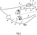
- FIG. 1 there is shown schematically, in half-section, the essential elements of a combustion chamber 11 installed inside a diffuser casing 16.
- the assembly forms a combustion chamber module of a turbomachine such as an airplane jet engine.
- this module is inserted between a compressor located upstream and a turbine installed downstream.
- the pressurized air is introduced through a pipe 30 into an annular cavity 32 inside which the combustion chamber is installed.
- the latter comprises an annular outer wall 14, an annular inner wall 15 and a chamber bottom 13, also annular, where fuel is injected and mixed with the air supplied by the compressor.
- the downstream end 12 of the outer wall 14 of the combustion chamber is connected to the wall of the diffuser casing 16 by a connecting piece 17. The latter is welded to said downstream end 12.
- the connecting piece 17 comprises a connecting flange 19 at its downstream end and a plurality of fixing lugs 36.
- the connecting flange 19, annular, is welded to the downstream end 12 of the outer wall 14 of the chamber of combustion.
- the fixing lugs 36 are oriented radially both outward and upstream. Each leg end 38 is engaged in a groove 40 open laterally downstream. The groove 40 thus forms a hook. Each groove is defined in a boss 42 in excess thickness of the wall of the casing 16, projecting from the inner face of the latter. Thus, the casing has as many internal bosses as there are lugs 36 and each boss 42 is hollowed out laterally downstream to define a groove 40 forming the aforementioned hook.
- the lugs 36 and the bosses 42 are regularly distributed circumferentially. They are eighteen in number in the example described. Each groove 40 therefore receives the end 38 of a corresponding fixing lug 36.
- the end part of each tab has a boss 46 in contact with the radially outermost surface of the groove or (as shown) an area adjacent to the inner surface of the casing. This boss 46 is located here at a certain distance from the end of the tab.
- the lugs 36 are shaped so that, when cold, a clamping is exerted between the end of the lug, in this case here the boss 46, and the radially outermost surface of the groove or (according to the example) the internal surface of said casing 16, in the vicinity of this groove.
- the assembly is such that a small predetermined clearance exists when cold between the radially innermost face 47 of the hook-forming groove and the end 38 of the lug which penetrates into this groove. Tightening changes during operation, given the increase in temperature. For all stabilized operating points, there is clamping on one of the two faces of the groove. When hot, the tightening is transferred essentially to the radially innermost face 47 of the groove 40. This arrangement with double tightening changing according to the temperature makes it possible to reduce the maximum value of the tightening, in operation and therefore to limit the stresses.
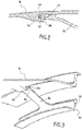
- the inner wall of the housing 16 is provided with a single aforementioned continuous groove 50 defined in an annular rib 52 projecting from the internal face of the housing.
- the groove 50 is made in this rib and opens laterally downstream. If the annular part 17 conforms to that which is illustrated in the picture 3 , the ends of the fixing lugs 36 are engaged in this single groove.
- this embodiment with a single groove 50 is more particularly advantageous when, as shown, the ends of all the fixing lugs 36 are joined by a ring 55 engaged in the groove 50 forming a hook, which is continuous.
- This ring has a rib 56 projecting from its outer surface, which is in contact, when cold, against the inner surface of the casing 16. This variant provides more rigidity to the assembly.
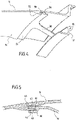
- each lug is shaped so as to have a groove 60 open upstream, capable of cooperating in the mounting position with one of the corresponding grooves 40 of the housing.
- the lugs 36 are shaped so that, when cold, clamping is exerted between the radially outermost surface 61 of the groove 60 defined at the end of each lug and the radially innermost surface 47 of the corresponding groove of the casing. .
- a clearance is defined when cold between the radially innermost surface 63 of the groove of the lug and the inner surface of the boss 42 in which the corresponding groove 40 of the casing is defined. When hot, this play disappears and the tightening refers to this location.
- grooves 40 could be replaced by a single continuous annular groove and the grooves 60 could form only one, annular, defined in a ring connecting the legs 36.
Landscapes
- Engineering & Computer Science (AREA)
- Chemical & Material Sciences (AREA)
- Mechanical Engineering (AREA)
- General Engineering & Computer Science (AREA)
- Combustion & Propulsion (AREA)
- Ceramic Engineering (AREA)
- Structures Of Non-Positive Displacement Pumps (AREA)
- Turbine Rotor Nozzle Sealing (AREA)
Claims (11)
- Brennkammermodul, umfassend eine ringförmige Brennkammer und ein Außengehäuse, wobei die Brennkammer am Außengehäuse befestigt ist, wobei das stromabwärtige Ende einer Außenwand (14) der Brennkammer an einem ringförmigen Verbindungsstück (17) befestigt ist, dadurch gekennzeichnet, dass das Verbindungsstück eine Vielzahl von Befestigungslaschen (36) umfasst, die radial nach außen und stromaufwärts gerichtet sind, wobei jedes Laschenende in eine Rille (40) eingreift, die seitlich stromabwärts offen ist, einen Haken bildet, mit der Innenwand des Gehäuses (16) verbunden ist, wobei das Verbindungsstück (17) an seinem stromabwärtigen Ende einen ringförmigen Verbindungsflansch (19) umfasst, wobei der Verbindungsflansch (19) mit dem stromabwärtigen Ende (12) der Außenwand (14) der Brennkammer verschweißt ist.
- Modul gemäß Anspruch 1, dadurch gekennzeichnet, dass die Befestigungslaschen (36) regelmäßig in Umfangsrichtung verteilt sind.
- Modul gemäß Anspruch 2, dadurch gekennzeichnet, dass die Befestigungslaschen (36) in der Anzahl von achtzehn vorhanden sind.
- Modul gemäß einem der vorhergehenden Ansprüche, dadurch gekennzeichnet, dass die Innenwand des Gehäuses mit einer Vielzahl von Rillen (40) versehen ist, die einen Haken bilden, einzeln ausgebildet und in Umfangsrichtung verteilt sind, um jeweils den vorgenannten Befestigungslaschen (36) zu entsprechen, wobei jede Rille das Ende einer Befestigungslasche aufnimmt.
- Modul gemäß einem der Ansprüche 1 bis 3, dadurch gekennzeichnet, dass die Innenwand des Gehäuses mit einer einzigen durchgehenden, ringförmigen Rille (50) versehen ist, in der die Enden aller Befestigungslaschen (36) in Eingriff sind.
- Modul gemäß Anspruch 5, dadurch gekennzeichnet, dass die Enden aller Befestigungslaschen durch einen Ring (55), der in der durchgehenden Rille in Eingriff ist, vereint sind.
- Modul gemäß einem der vorhergehenden Ansprüche, dadurch gekennzeichnet, dass die Befestigungslaschen (36) dazu vorgesehen sind, dass im kalten Zustand eine Klemmkraft zwischen dem Ende jeder Lasche und der radial äußersten Fläche einer solchen Rille oder der Innenfläche des Gehäuses ausgeübt wird.
- Modul gemäß Anspruch 7, dadurch gekennzeichnet, dass der äußerste Teil jeder Lasche einen Wulst (46) umfasst, der mit der radial äußersten Fläche der Rille oder der Innenfläche des Gehäuses in Kontakt ist.
- Modul gemäß einem der Ansprüche 1 bis 4, dadurch gekennzeichnet, dass das Ende jeder Lasche mit einer Rille (60) ausgebildet ist, die stromaufwärts offen ist und mit einer entsprechenden vorgenannten Rille (40) des Gehäuses zusammenwirkt.
- Modul gemäß Anspruch 9, dadurch gekennzeichnet, dass die Laschen (36) dazu vorgesehen sind, dass im kalten Zustand eine Klemmkraft zwischen der radial äußersten Fläche der Rille jeder Lasche und der radial innersten Fläche der entsprechenden Rille des Gehäuses ausgeübt wird.
- Turbomaschine, umfassend ein Brennkammermodul gemäß einem der vorhergehenden Ansprüche.
Applications Claiming Priority (1)
| Application Number | Priority Date | Filing Date | Title |
|---|---|---|---|
| FR0510585A FR2892181B1 (fr) | 2005-10-18 | 2005-10-18 | Fixation d'une chambre de combustion a l'interieur de son carter |
Publications (3)
| Publication Number | Publication Date |
|---|---|
| EP1777460A1 EP1777460A1 (de) | 2007-04-25 |
| EP1777460B1 EP1777460B1 (de) | 2017-11-29 |
| EP1777460B2 true EP1777460B2 (de) | 2023-01-18 |
Family
ID=36273376
Family Applications (1)
| Application Number | Title | Priority Date | Filing Date |
|---|---|---|---|
| EP06122476.2A Active EP1777460B2 (de) | 2005-10-18 | 2006-10-17 | Fastening of a combustion chamber inside its housing |
Country Status (3)
| Country | Link |
|---|---|
| US (1) | US7752851B2 (de) |
| EP (1) | EP1777460B2 (de) |
| FR (1) | FR2892181B1 (de) |
Families Citing this family (11)
| Publication number | Priority date | Publication date | Assignee | Title |
|---|---|---|---|---|
| FR2906350B1 (fr) * | 2006-09-22 | 2009-03-20 | Snecma Sa | Chambre de combustion annulaire d'une turbomachine |
| FR2919380B1 (fr) * | 2007-07-26 | 2013-10-25 | Snecma | Chambre de combustion d'une turbomachine. |
| FR2920524B1 (fr) * | 2007-08-30 | 2013-11-01 | Snecma | Turbomachine a chambre annulaire de combustion |
| FR2930628B1 (fr) * | 2008-04-24 | 2010-04-30 | Snecma | Chambre annulaire de combustion pour turbomachine |
| US8651809B2 (en) * | 2010-10-13 | 2014-02-18 | General Electric Company | Apparatus and method for aligning a turbine casing |
| US9297536B2 (en) * | 2012-05-01 | 2016-03-29 | United Technologies Corporation | Gas turbine engine combustor surge retention |
| DE102014204481A1 (de) | 2014-03-11 | 2015-09-17 | Rolls-Royce Deutschland Ltd & Co Kg | Brennkammer einer Gasturbine |
| DE102014204476A1 (de) * | 2014-03-11 | 2015-10-01 | Rolls-Royce Deutschland Ltd & Co Kg | Brennkammer einer Gasturbine |
| JP6429764B2 (ja) * | 2015-12-24 | 2018-11-28 | 三菱重工航空エンジン株式会社 | ガスタービン |
| US10550725B2 (en) * | 2016-10-19 | 2020-02-04 | United Technologies Corporation | Engine cases and associated flange |
| FR3111964B1 (fr) * | 2020-06-26 | 2023-03-17 | Safran Helicopter Engines | Assemblage d’une pièce de chambre de combustion par recouvrement par une autre pièce |
Citations (2)
| Publication number | Priority date | Publication date | Assignee | Title |
|---|---|---|---|---|
| US5528896A (en) † | 1993-11-10 | 1996-06-25 | Societe Nationale D'etude Et De Construction De Moteurs D'aviation (S.N.E.C.M.A.) | Gas-flow separator for a double dome gas turbine engine combustion chamber |
| US20030141388A1 (en) † | 2000-06-28 | 2003-07-31 | Johnson Arthur Wesley | Methods and apparatus for decreasing combustor emissions |
Family Cites Families (14)
| Publication number | Priority date | Publication date | Assignee | Title |
|---|---|---|---|---|
| GB717581A (en) * | 1951-06-25 | 1954-10-27 | Parsons C A & Co Ltd | Improvements in and relating to gas turbine power plants |
| GB1539035A (en) * | 1976-04-22 | 1979-01-24 | Rolls Royce | Combustion chambers for gas turbine engines |
| GB1578474A (en) * | 1976-06-21 | 1980-11-05 | Gen Electric | Combustor mounting arrangement |
| US6286317B1 (en) * | 1998-12-18 | 2001-09-11 | General Electric Company | Cooling nugget for a liner of a gas turbine engine combustor having trapped vortex cavity |
| FR2825783B1 (fr) * | 2001-06-06 | 2003-11-07 | Snecma Moteurs | Accrochage de chambre de combustion cmc de turbomachine par pattes brasees |
| FR2825781B1 (fr) * | 2001-06-06 | 2004-02-06 | Snecma Moteurs | Montage elastique de chambre ce combustion cmc de turbomachine dans un carter metallique |
| FR2825785B1 (fr) * | 2001-06-06 | 2004-08-27 | Snecma Moteurs | Liaison de chambre de combustion cmc de turbomachine en deux parties |
| US6851263B2 (en) * | 2002-10-29 | 2005-02-08 | General Electric Company | Liner for a gas turbine engine combustor having trapped vortex cavity |
| US6904676B2 (en) * | 2002-12-04 | 2005-06-14 | General Electric Company | Methods for replacing a portion of a combustor liner |
| FR2855249B1 (fr) * | 2003-05-20 | 2005-07-08 | Snecma Moteurs | Chambre de combustion ayant une liaison souple entre un fond de chambre et une paroi de chambre |
| FR2871847B1 (fr) * | 2004-06-17 | 2006-09-29 | Snecma Moteurs Sa | Montage d'un distributeur de turbine sur une chambre de combustion a parois en cmc dans une turbine a gaz |
| FR2871846B1 (fr) * | 2004-06-17 | 2006-09-29 | Snecma Moteurs Sa | Chambre de combustion en cmc de turbine a gaz supportee dans un carter metallique par des organes de liaison en cmc |
| FR2890156A1 (fr) * | 2005-08-31 | 2007-03-02 | Snecma | Chambre de combustion d'une turbomachine |
| US7578134B2 (en) * | 2006-01-11 | 2009-08-25 | General Electric Company | Methods and apparatus for assembling gas turbine engines |
-
2005
- 2005-10-18 FR FR0510585A patent/FR2892181B1/fr not_active Expired - Lifetime
-
2006
- 2006-10-16 US US11/549,796 patent/US7752851B2/en active Active
- 2006-10-17 EP EP06122476.2A patent/EP1777460B2/de active Active
Patent Citations (2)
| Publication number | Priority date | Publication date | Assignee | Title |
|---|---|---|---|---|
| US5528896A (en) † | 1993-11-10 | 1996-06-25 | Societe Nationale D'etude Et De Construction De Moteurs D'aviation (S.N.E.C.M.A.) | Gas-flow separator for a double dome gas turbine engine combustion chamber |
| US20030141388A1 (en) † | 2000-06-28 | 2003-07-31 | Johnson Arthur Wesley | Methods and apparatus for decreasing combustor emissions |
Also Published As
| Publication number | Publication date |
|---|---|
| FR2892181B1 (fr) | 2008-02-01 |
| FR2892181A1 (fr) | 2007-04-20 |
| EP1777460A1 (de) | 2007-04-25 |
| EP1777460B1 (de) | 2017-11-29 |
| US7752851B2 (en) | 2010-07-13 |
| US20070107439A1 (en) | 2007-05-17 |
Similar Documents
| Publication | Publication Date | Title |
|---|---|---|
| EP1265035B1 (de) | Doppelbefestigung einer Turbinenbrennkammer aus keramischem Matrix-Verbundwerkstoff | |
| EP2836684B1 (de) | Turbomaschine, wie turbostrahltriebwerk oder turbopropellertriebwerk für flugzeuge | |
| WO2009118478A1 (fr) | Chambre de combustion de turbomachine | |
| EP1777460B2 (de) | Fastening of a combustion chamber inside its housing | |
| FR2930591A1 (fr) | Optimisation du positionnement angulaire d'un distributeur de turbine en sortie d'une chambre de combustion de turbomachine | |
| FR3004518A1 (fr) | Chambre de combustion annulaire d'une turbomachine | |
| FR2998038A1 (fr) | Chambre de combustion pour une turbomachine | |
| EP1950497B1 (de) | Verteilerkammer für gasturbinenmotor, brennkammer und gasturbinenmotor, der diese umfasst | |
| EP4237678A1 (de) | Turbomaschinen-turbinenanordnung | |
| EP4251925B1 (de) | Verbrennungsmodul für eine turbomaschine | |
| EP3575689B1 (de) | Gasverbrennungsmodul eines turbotriebwerks mit anschlag am brennkammerboden | |
| EP4240957B1 (de) | Anordnung für eine turbomaschine | |
| WO2009153480A2 (fr) | Turbomachine avec diffuseur | |
| EP4240954B1 (de) | Befestigung eines abgaskonus in einer turbomaschinendüse | |
| FR2825778A1 (fr) | Liaison coulissante entre un systeme d'injection d'une chambre de combustion et un fond de cette chambre de combustion | |
| FR2992018A1 (fr) | Montage d'un distributeur de turbine haute-pression sur une chambre a combustion d'une turbomachine | |
| FR3115827A1 (fr) | Fixation d’un cône d’éjection dans une tuyère de turbomachine | |
| EP3976939B1 (de) | Modul eines flugzeugturbinentriebwerks | |
| FR2991387A1 (fr) | Turbomachine, telle qu'un turboreacteur ou un turbopropulseur d'avion | |
| FR3116305A1 (fr) | Arbre de liaison d’un corps haute pression d’une turbomachine | |
| EP3976935B1 (de) | Dichtring für ein laufrad einer turbomaschinenturbine | |
| FR2996598A1 (fr) | Chambre de combustion pour une turbomachine | |
| EP3568638B1 (de) | Brennkammer für einen turbinenmotor | |
| FR3111964A1 (fr) | Assemblage d’une pièce de chambre de combustion par recouvrement par une autre pièce | |
| FR2900460A1 (fr) | Systeme annulaire de post-combustion d'une turbomachine |
Legal Events
| Date | Code | Title | Description |
|---|---|---|---|
| PUAI | Public reference made under article 153(3) epc to a published international application that has entered the european phase |
Free format text: ORIGINAL CODE: 0009012 |
|
| 17P | Request for examination filed |
Effective date: 20061017 |
|
| AK | Designated contracting states |
Kind code of ref document: A1 Designated state(s): AT BE BG CH CY CZ DE DK EE ES FI FR GB GR HU IE IS IT LI LT LU LV MC NL PL PT RO SE SI SK TR |
|
| AX | Request for extension of the european patent |
Extension state: AL BA HR MK YU |
|
| AKX | Designation fees paid |
Designated state(s): DE FR GB IT |
|
| GRAP | Despatch of communication of intention to grant a patent |
Free format text: ORIGINAL CODE: EPIDOSNIGR1 |
|
| STAA | Information on the status of an ep patent application or granted ep patent |
Free format text: STATUS: GRANT OF PATENT IS INTENDED |
|
| INTG | Intention to grant announced |
Effective date: 20170410 |
|
| GRAS | Grant fee paid |
Free format text: ORIGINAL CODE: EPIDOSNIGR3 |
|
| GRAJ | Information related to disapproval of communication of intention to grant by the applicant or resumption of examination proceedings by the epo deleted |
Free format text: ORIGINAL CODE: EPIDOSDIGR1 |
|
| GRAL | Information related to payment of fee for publishing/printing deleted |
Free format text: ORIGINAL CODE: EPIDOSDIGR3 |
|
| STAA | Information on the status of an ep patent application or granted ep patent |
Free format text: STATUS: REQUEST FOR EXAMINATION WAS MADE |
|
| INTC | Intention to grant announced (deleted) | ||
| GRAR | Information related to intention to grant a patent recorded |
Free format text: ORIGINAL CODE: EPIDOSNIGR71 |
|
| STAA | Information on the status of an ep patent application or granted ep patent |
Free format text: STATUS: GRANT OF PATENT IS INTENDED |
|
| GRAA | (expected) grant |
Free format text: ORIGINAL CODE: 0009210 |
|
| STAA | Information on the status of an ep patent application or granted ep patent |
Free format text: STATUS: THE PATENT HAS BEEN GRANTED |
|
| INTG | Intention to grant announced |
Effective date: 20170922 |
|
| AK | Designated contracting states |
Kind code of ref document: B1 Designated state(s): DE FR GB IT |
|
| REG | Reference to a national code |
Ref country code: GB Ref legal event code: FG4D Free format text: NOT ENGLISH |
|
| REG | Reference to a national code |
Ref country code: DE Ref legal event code: R096 Ref document number: 602006054217 Country of ref document: DE |
|
| RAP2 | Party data changed (patent owner data changed or rights of a patent transferred) |
Owner name: SAFRAN AIRCRAFT ENGINES |
|
| REG | Reference to a national code |
Ref country code: DE Ref legal event code: R026 Ref document number: 602006054217 Country of ref document: DE |
|
| PLBI | Opposition filed |
Free format text: ORIGINAL CODE: 0009260 |
|
| PLAX | Notice of opposition and request to file observation + time limit sent |
Free format text: ORIGINAL CODE: EPIDOSNOBS2 |
|
| REG | Reference to a national code |
Ref country code: FR Ref legal event code: PLFP Year of fee payment: 13 |
|
| 26 | Opposition filed |
Opponent name: UNITED TECHNOLOGIES CORPORATION Effective date: 20180829 |
|
| PLBB | Reply of patent proprietor to notice(s) of opposition received |
Free format text: ORIGINAL CODE: EPIDOSNOBS3 |
|
| PLAB | Opposition data, opponent's data or that of the opponent's representative modified |
Free format text: ORIGINAL CODE: 0009299OPPO |
|
| R26 | Opposition filed (corrected) |
Opponent name: RAYTHEON TECHNOLOGIES CORPORATION Effective date: 20180829 |
|
| APAH | Appeal reference modified |
Free format text: ORIGINAL CODE: EPIDOSCREFNO |
|
| APBM | Appeal reference recorded |
Free format text: ORIGINAL CODE: EPIDOSNREFNO |
|
| APBP | Date of receipt of notice of appeal recorded |
Free format text: ORIGINAL CODE: EPIDOSNNOA2O |
|
| APBU | Appeal procedure closed |
Free format text: ORIGINAL CODE: EPIDOSNNOA9O |
|
| PUAH | Patent maintained in amended form |
Free format text: ORIGINAL CODE: 0009272 |
|
| STAA | Information on the status of an ep patent application or granted ep patent |
Free format text: STATUS: PATENT MAINTAINED AS AMENDED |
|
| 27A | Patent maintained in amended form |
Effective date: 20230118 |
|
| AK | Designated contracting states |
Kind code of ref document: B2 Designated state(s): DE FR GB IT |
|
| REG | Reference to a national code |
Ref country code: DE Ref legal event code: R102 Ref document number: 602006054217 Country of ref document: DE |
|
| PGFP | Annual fee paid to national office [announced via postgrant information from national office to epo] |
Ref country code: DE Payment date: 20251020 Year of fee payment: 20 |
|
| PGFP | Annual fee paid to national office [announced via postgrant information from national office to epo] |
Ref country code: GB Payment date: 20251029 Year of fee payment: 20 |
|
| PGFP | Annual fee paid to national office [announced via postgrant information from national office to epo] |
Ref country code: IT Payment date: 20251031 Year of fee payment: 20 |
|
| PGFP | Annual fee paid to national office [announced via postgrant information from national office to epo] |
Ref country code: FR Payment date: 20251023 Year of fee payment: 20 |