EP4240957B1 - Anordnung für eine turbomaschine - Google Patents
Anordnung für eine turbomaschine Download PDFInfo
- Publication number
- EP4240957B1 EP4240957B1 EP21815238.7A EP21815238A EP4240957B1 EP 4240957 B1 EP4240957 B1 EP 4240957B1 EP 21815238 A EP21815238 A EP 21815238A EP 4240957 B1 EP4240957 B1 EP 4240957B1
- Authority
- EP
- European Patent Office
- Prior art keywords
- cone
- exhaust
- flange
- assembly according
- lugs
- Prior art date
- Legal status (The legal status is an assumption and is not a legal conclusion. Google has not performed a legal analysis and makes no representation as to the accuracy of the status listed.)
- Active
Links
Images


Classifications
-
- F—MECHANICAL ENGINEERING; LIGHTING; HEATING; WEAPONS; BLASTING
- F02—COMBUSTION ENGINES; HOT-GAS OR COMBUSTION-PRODUCT ENGINE PLANTS
- F02K—JET-PROPULSION PLANTS
- F02K1/00—Plants characterised by the form or arrangement of the jet pipe or nozzle; Jet pipes or nozzles peculiar thereto
- F02K1/04—Mounting of an exhaust cone in the jet pipe
-
- B—PERFORMING OPERATIONS; TRANSPORTING
- B64—AIRCRAFT; AVIATION; COSMONAUTICS
- B64D—EQUIPMENT FOR FITTING IN OR TO AIRCRAFT; FLIGHT SUITS; PARACHUTES; ARRANGEMENT OR MOUNTING OF POWER PLANTS OR PROPULSION TRANSMISSIONS IN AIRCRAFT
- B64D33/00—Arrangement in aircraft of power plant parts or auxiliaries not otherwise provided for
- B64D33/04—Arrangement in aircraft of power plant parts or auxiliaries not otherwise provided for of exhaust outlets or jet pipes
- B64D33/06—Silencing exhaust or propulsion jets
-
- F—MECHANICAL ENGINEERING; LIGHTING; HEATING; WEAPONS; BLASTING
- F01—MACHINES OR ENGINES IN GENERAL; ENGINE PLANTS IN GENERAL; STEAM ENGINES
- F01D—NON-POSITIVE DISPLACEMENT MACHINES OR ENGINES, e.g. STEAM TURBINES
- F01D25/00—Component parts, details, or accessories, not provided for in, or of interest apart from, other groups
- F01D25/30—Exhaust heads, chambers, or the like
-
- F—MECHANICAL ENGINEERING; LIGHTING; HEATING; WEAPONS; BLASTING
- F01—MACHINES OR ENGINES IN GENERAL; ENGINE PLANTS IN GENERAL; STEAM ENGINES
- F01N—GAS-FLOW SILENCERS OR EXHAUST APPARATUS FOR MACHINES OR ENGINES IN GENERAL; GAS-FLOW SILENCERS OR EXHAUST APPARATUS FOR INTERNAL-COMBUSTION ENGINES
- F01N13/00—Exhaust or silencing apparatus characterised by constructional features
- F01N13/18—Construction facilitating manufacture, assembly, or disassembly
- F01N13/1805—Fixing exhaust manifolds, exhaust pipes or pipe sections to each other, to engine or to vehicle body
- F01N13/1827—Sealings specially adapted for exhaust systems
-
- F—MECHANICAL ENGINEERING; LIGHTING; HEATING; WEAPONS; BLASTING
- F02—COMBUSTION ENGINES; HOT-GAS OR COMBUSTION-PRODUCT ENGINE PLANTS
- F02C—GAS-TURBINE PLANTS; AIR INTAKES FOR JET-PROPULSION PLANTS; CONTROLLING FUEL SUPPLY IN AIR-BREATHING JET-PROPULSION PLANTS
- F02C7/00—Features, components parts, details or accessories, not provided for in, or of interest apart form groups F02C1/00 - F02C6/00; Air intakes for jet-propulsion plants
- F02C7/24—Heat or noise insulation
-
- F—MECHANICAL ENGINEERING; LIGHTING; HEATING; WEAPONS; BLASTING
- F02—COMBUSTION ENGINES; HOT-GAS OR COMBUSTION-PRODUCT ENGINE PLANTS
- F02K—JET-PROPULSION PLANTS
- F02K1/00—Plants characterised by the form or arrangement of the jet pipe or nozzle; Jet pipes or nozzles peculiar thereto
- F02K1/78—Other construction of jet pipes
- F02K1/80—Couplings or connections
-
- F—MECHANICAL ENGINEERING; LIGHTING; HEATING; WEAPONS; BLASTING
- F02—COMBUSTION ENGINES; HOT-GAS OR COMBUSTION-PRODUCT ENGINE PLANTS
- F02K—JET-PROPULSION PLANTS
- F02K1/00—Plants characterised by the form or arrangement of the jet pipe or nozzle; Jet pipes or nozzles peculiar thereto
- F02K1/78—Other construction of jet pipes
- F02K1/82—Jet pipe walls, e.g. liners
-
- F—MECHANICAL ENGINEERING; LIGHTING; HEATING; WEAPONS; BLASTING
- F05—INDEXING SCHEMES RELATING TO ENGINES OR PUMPS IN VARIOUS SUBCLASSES OF CLASSES F01-F04
- F05D—INDEXING SCHEME FOR ASPECTS RELATING TO NON-POSITIVE-DISPLACEMENT MACHINES OR ENGINES, GAS-TURBINES OR JET-PROPULSION PLANTS
- F05D2230/00—Manufacture
- F05D2230/50—Building or constructing in particular ways
- F05D2230/51—Building or constructing in particular ways in a modular way, e.g. using several identical or complementary parts or features
-
- F—MECHANICAL ENGINEERING; LIGHTING; HEATING; WEAPONS; BLASTING
- F05—INDEXING SCHEMES RELATING TO ENGINES OR PUMPS IN VARIOUS SUBCLASSES OF CLASSES F01-F04
- F05D—INDEXING SCHEME FOR ASPECTS RELATING TO NON-POSITIVE-DISPLACEMENT MACHINES OR ENGINES, GAS-TURBINES OR JET-PROPULSION PLANTS
- F05D2260/00—Function
- F05D2260/30—Retaining components in desired mutual position
- F05D2260/31—Retaining bolts or nuts
-
- F—MECHANICAL ENGINEERING; LIGHTING; HEATING; WEAPONS; BLASTING
- F05—INDEXING SCHEMES RELATING TO ENGINES OR PUMPS IN VARIOUS SUBCLASSES OF CLASSES F01-F04
- F05D—INDEXING SCHEME FOR ASPECTS RELATING TO NON-POSITIVE-DISPLACEMENT MACHINES OR ENGINES, GAS-TURBINES OR JET-PROPULSION PLANTS
- F05D2300/00—Materials; Properties thereof
- F05D2300/60—Properties or characteristics given to material by treatment or manufacturing
- F05D2300/603—Composites; e.g. fibre-reinforced
- F05D2300/6033—Ceramic matrix composites [CMC]
-
- Y—GENERAL TAGGING OF NEW TECHNOLOGICAL DEVELOPMENTS; GENERAL TAGGING OF CROSS-SECTIONAL TECHNOLOGIES SPANNING OVER SEVERAL SECTIONS OF THE IPC; TECHNICAL SUBJECTS COVERED BY FORMER USPC CROSS-REFERENCE ART COLLECTIONS [XRACs] AND DIGESTS
- Y02—TECHNOLOGIES OR APPLICATIONS FOR MITIGATION OR ADAPTATION AGAINST CLIMATE CHANGE
- Y02T—CLIMATE CHANGE MITIGATION TECHNOLOGIES RELATED TO TRANSPORTATION
- Y02T50/00—Aeronautics or air transport
- Y02T50/60—Efficient propulsion technologies, e.g. for aircraft
Definitions
- the invention relates to an assembly for a turbomachine, in particular an ejection assembly for an aircraft turbojet or turboprop.
- a propulsion system for an aircraft typically comprises a turbomachine, for example a turbojet, a nacelle and a mast or attachment pylon intended to allow the propulsion system to be attached to a structural part, for example under the wing, of the aircraft.
- a turbomachine for example a turbojet
- a nacelle for example a nacelle
- a mast or attachment pylon intended to allow the propulsion system to be attached to a structural part, for example under the wing, of the aircraft.
- the turbomachine is for example a double-flow turbojet.
- a turbomachine 1, illustrated in figure 1 has an X axis and comprises, from upstream to downstream in the direction of circulation of the gases within the turbomachine, a fan 2, a low pressure compressor 3, a high pressure compressor 4, a combustion chamber 5, a high pressure turbine 6 and a low pressure turbine 7.
- upstream and downstream are defined in relation to the direction of gas flow within the turbomachine.
- axial, radial and circumferential are defined relative to the X axis of the turbomachine.
- the air F entering at the blower is divided into a primary air flow F1 circulating through a so-called primary vein 8 and into a secondary air flow F2 circulating through a so-called secondary vein 9, surrounding the primary vein 8.
- the low and high pressure compressors 3, 4, the combustion chamber 5 and the high and low pressure turbines 6, 7 are located at the level of the primary vein 8.
- the high-pressure turbine 6 drives the high-pressure compressor 4 via a so-called high-pressure shaft.
- the low-pressure turbine 7 drives the low-pressure compressor 3 and the blower 2, via a so-called low-pressure shaft and possibly via a speed reducer in the case where the rotation speed of the blower 2 is lower than the rotation speed of the low-pressure compressor 3.
- turbomachine 1 Most of the thrust generated by turbomachine 1 is produced by secondary flow F2, downstream of fan 2.
- the fan 2 is surrounded by a fan casing 10, a so-called intermediate casing 11 being located downstream of the fan casing 10.
- the intermediate casing 11 comprises a radially external shroud 12 located in the extension of the fan casing 10 and a so-called inter-vein part 13, located between the primary 8 and secondary 9 veins.
- the inter-vein part 13 has a separating spout 14 at its upstream end and is connected to the external ferrule 12 by so-called structural arms 15.
- the turbomachine 1 also comprises a central casing 16, located downstream of the inter-vein part 13 of the intermediate casing 11, and an exhaust casing 17, located downstream of the central casing 16 and on which an ejection cone 18 is attached.
- the exhaust casing 17 comprises a radially internal shell 19 and a radially external shell 20, connected by radially extending blades.
- the internal shells 19 and external shells 20 of the exhaust casing 17 or engine casing delimit between them the downstream end of the primary stream 8.
- the nacelle 21 of the propulsion unit conventionally comprises a fan nacelle 22, surrounding the fan 2 as well as the fan casing 10 and the external shroud 12 of the intermediate casing 11.
- the fan nacelle 22 forms an air inlet lip 23 at its upstream end.
- the nacelle 21 further comprises an engine nacelle 24 surrounding the zones of the turbomachine 1 comprising the high-pressure compressor 4, the combustion chamber 5, the high-pressure turbine 6, and the low-pressure turbine 7 in particular.
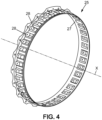
- the upstream end of the ejection cone 18 is connected to the downstream end of the internal shell 19 of the exhaust casing 17 by means of an annular connecting flange 25 (also visible in FIG. figure 4 ).
- the cone 18 is generally made of ceramic matrix composite material, also referred to by the English acronym CMC.
- the cone 18 may also include an internal acoustic structure 26.
- the internal shell 19 of the exhaust casing 18 is metallic, for example made of a nickel-based alloy, for example Inconel.
- the flange 25 is metallic, for example made of a nickel-based alloy (Inconel for example), and comprises an annular part 27 of axis X, from which flexible legs 28 extend.
- the legs 28 are regularly distributed around the circumference.
- Such flexible or supple tabs 28 make it possible to compensate for the differential expansion phenomena occurring between the internal shell 19 of the exhaust casing 17 and the cone 18, these two elements 17, 18 being made of different materials.
- Such an annular flange 25 is generally manufactured by machining a large raw element, such manufacturing being relatively expensive.
- the invention aims to remedy this drawback in a simple, reliable and inexpensive manner.
- the invention relates to an assembly for a turbomachine comprising an ejection cone and an exhaust casing comprising an annular internal shroud, the ejection cone and the exhaust casing extending around an axis, the ejection cone comprising an external surface extending in the extension of said internal shell, the ejection cone being connected to the exhaust casing by means of a flange, said flange comprising an upstream part fixed to the exhaust casing and lugs extending downstream from said upstream part, the ejection cone being fixed to said lugs, characterized in that the flange is sectorized and is formed of several angular sectors arranged circumferentially adjacent, each flange sector comprising at least one lug extending rectilinearly along an axis parallel to the axis of the cone.
- each flange sector using a raw material element of smaller dimensions than in the case of the prior art, which makes it possible to limit costs and machining times.
- Such a structure also allows the implementation of mass production of the flange sectors.
- each leg is flat and extends along a straight axis parallel to the axis of the exhaust casing and the cone, i.e. parallel to the axis of the turbomachine, makes it possible to limit the mechanical stresses in each flange sector, and in particular in the legs, so as to avoid any premature degradation.
- Such a structure of the legs also makes it easier to produce the sectors and to limit the size of each sector.
- the legs may be formed by blades, for example flat. Each leg may have a substantially constant thickness. Each leg may have a generally rectangular shape, seen radially from the outside to the inside. Each leg may have a rectangular section.
- Adjacent sectors may be arranged end to end or may be regularly spaced apart from each other in the circumferential direction.
- Each tab may be flexible or elastically deformable in the radial direction, so as to compensate for possible differential expansion effects between the cone and the exhaust casing, when these are made of different materials for example.
- the thickness of each tab i.e. its dimension in the radial direction, is for example between 0.5 mm and 10 mm.
- the cone is for example made, at least in part, of ceramic matrix composite material, also known by the English acronym CMC.
- CMC ceramic matrix composite material
- the exhaust casing is for example made, at least in part, of metallic material capable of withstanding high temperatures during operation of the turbomachine.
- Each flange sector can extend over an angular range of less than 180°.
- Each flange sector can have between 1 and 100 legs, preferably between 1 and 10 legs, preferably between 3 and 6 legs.
- the assembly may include means for rotational coupling and/or positioning of each flange sector.
- the rotational coupling and/or positioning means may comprise at least one positioning stud formed on the corresponding sector, engaged in a recess or a complementary orifice of the exhaust casing or the cone, or vice versa.
- the positioning stud may extend radially from the upstream portion of each sector and be engaged in a recess or orifice of complementary shape in the exhaust casing.
- the recess or orifice may be provided in an element fixed to the exhaust casing or to the cone.
- the rotational coupling and/or positioning means may comprise at least one flat formed on the corresponding sector, bearing on an edge or a corresponding flat surface of the exhaust casing or the cone, or vice versa.
- the flat part can come to rest on an edge or a corresponding flat surface of an element fixed to the exhaust housing or to the cone.
- the rotational coupling means are capable of preventing rotation of the corresponding sector relative to an axis perpendicular to the axis of the cone and the exhaust casing, i.e. relative to a radial axis.
- the flat part may be formed by a projecting area extending from the upstream portion of the corresponding sector and may bear on an edge or a corresponding flat area of the exhaust casing or of an element fixed to said exhaust casing.
- the rotational coupling and/or positioning means may comprise two flats, formed for example by two projecting zones, circumferentially spaced from each other.
- the cone may comprise a radially internal skin and a radially external skin, delimiting between them a box, the external skin forming at least in part said external surface of the ejection cone.
- the box can be an acoustic box.
- the acoustic enclosure helps to limit noise pollution caused by the flow of gases from the turbine.
- the radially inner skin and the radially outer skin may be connected by at least one radially extending wall.
- the radially outer skin may extend axially upstream to the exhaust housing, the flange sectors being located radially inside the radially outer skin, the lugs being fixed to the radially inner skin.
- the upstream end of the outer skin can then be spaced a limited clearance from the exhaust casing.
- An annular gasket may extend between the exhaust housing and the outer skin, so as to prevent the introduction of leakage air through the aforementioned clearance.
- each sector can be fixed to a radial or axial downstream part of the exhaust casing, directly or by means of a connecting element.
- the connecting element may have an L-shaped section.
- the upstream part of each sector can be fixed to the exhaust housing by means of at least one bolt.
- Each leg of each sector can be fixed to the exhaust cone by means of at least one bolt.
- the invention also relates to a turbomachine comprising at least one assembly of the aforementioned type.
- FIGS. 5 to 8 illustrate an exhaust assembly for an aircraft turbomachine 1 according to an embodiment of the invention.
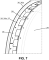
- This assembly comprises an exhaust casing 17 comprising, as previously, a radially external internal annular shell 19 and a radially external annular shell 20, connected by radial blades. Only the internal shell 19 is illustrated in figures 6 And 7 .
- the assembly further comprises an ejection cone 18 comprising a radially internal skin 29 and a radially external skin 30, delimiting between them a box, for example an acoustic box 31.
- the radially external skin 30 is a so-called acoustic skin and extends axially upstream to the internal shell 19 of the exhaust casing 17.
- the upstream end 30a of the external skin 30 is spaced by an axial clearance j at least equal to 0.2 mm, for example, relative to the exhaust casing 17.
- An annular seal 32 extends between the downstream end of the internal shell 19 of the exhaust casing 17 and the external skin 30, so as to prevent the introduction of leakage air through the aforementioned clearance j.
- the downstream end of said internal shell 19 comprises an annular rim 33 extending axially, offset radially inwards relative to the radially external surface 34 of the internal shell 17 intended to delimit the primary vein 8.
- a sectored annular flange 25 connects the annular rim 33 and the upstream end 29a of the internal skin 29 of the ejection cone 18.
- the flange 25 is formed of several angular sectors 25a arranged circumferentially end to end, each flange sector 25a comprising an upstream portion 35 extending circumferentially from which one or more flat legs 28 extend rectilinearly along an axis parallel to the axis X of the cone 18.
- the legs 28 are regularly distributed over the circumference of the flange 25.
- each sector 25a is fixed to the rim 33 by means of fixing means comprising for example one or more bolts 36, here 4 bolts regularly distributed in the circumferential direction and sometimes illustrated schematically by axis lines.
- each leg 28 is fixed to the upstream end 29a of the inner skin 29 of the cone 18 by means of fixing means comprising for example one or more bolts 37, here a single bolt, sometimes represented by center lines.
- fixing means comprising for example one or more bolts 37, here a single bolt, sometimes represented by center lines.
- fixing means by rivets or by welding are also possible for fixing the upstream part 35 or the legs 28 of each sector 25a.
- each flange 25 comprising 8 sectors.
- Each leg 28 has a substantially constant thickness, a rectangular section and a generally rectangular shape, seen radially from the outside towards the inside.
- the legs 28 are sufficiently flexible and supple to be elastically deformable and to compensate for the differential expansion effects between the cone 18 and the exhaust casing 17.
- the exhaust casing 17 is for example made of a metallic material, for example a nickel-based alloy, for example Inconel.
- the skins 29, 30 of the cone 18 are for example made of a ceramic matrix composite material, the differences in material generating such differential expansions depending on the operating temperature.
- each sector 25a comprises a single tab 28, the number of sectors 25a of the flange 25 then being between 1 and 200.
- the upstream part 35 is fixed to the casing 17 by means of at least two bolts 36.
- FIG. 10 schematically illustrates the assembly of the sectors 25a of flange 25 relative to the downstream end of the internal shell 19 of the casing 17, on the one hand, and relative to the internal skin 29 of the cone 18, on the other hand.
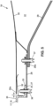
- FIG 11 illustrates another embodiment, where the axial rim 33 is formed by an intermediate connecting element 38.
- This element 38 comprises a radial annular part 39, fixed by any suitable means to a radial annular part 40 of the downstream end of the internal ferrule 19, and an axial or cylindrical annular part, forming the rim 33 used for fixing the upstream part 35 of each sector 25a.
- each sector 25a comprises a radial flange 39 extending radially outwards, fixed to a radial annular portion 40 of the downstream end of the internal shell 19 of the exhaust casing 17.
- each sector 25a comprises a single leg 28.
- the upstream part 35 comprises a hole 41 allowing the passage of a fixing means, for example a screw of a bolt 36, and a stud 42 engaged in an orifice or a recess 43 of complementary shape of the rim 33, the fixing means 36 being circumferentially offset from the stud 42.
- the fixing means 36, the orifice 42 and the recess 43 thus form means making it possible to prevent the rotation of the sector 25a relative to an axis or a radial direction.
- the upstream part 35 comprises two flats formed by studs 44 extending radially inwards for example.
- the studs 44 are circumferentially spaced from each other and bear on the downstream edge of the axial flange 33.
- the upstream part 35 also comprises fixing means, formed by one or more bolts 37 for example.
Landscapes
- Engineering & Computer Science (AREA)
- Chemical & Material Sciences (AREA)
- Combustion & Propulsion (AREA)
- Mechanical Engineering (AREA)
- General Engineering & Computer Science (AREA)
- Aviation & Aerospace Engineering (AREA)
- Structures Of Non-Positive Displacement Pumps (AREA)
- Supercharger (AREA)
- Turbine Rotor Nozzle Sealing (AREA)
Claims (10)
- Anordnung für eine Turbomaschine bzw. ein Turbotriebwerk (1) mit einem Ausstoßkonus (18) und einem Austrittsgehäuse (17), das einen inneren Mantelring (19) aufweist, wobei sich der Ausstoßkonus (18) und das Austrittsgehäuse (17) um eine Achse (X) herum erstrecken, wobei der Ausstoßkonus (18) eine Außenfläche aufweist, die sich in Fortsetzung des inneren Mantelrings (19) erstreckt, wobei der Ausstoßkonus (18) über einen Flansch (25) mit dem Austrittsgehäuse (17) verbunden ist, wobei der Flansch (25) einen stromaufwärtigen Abschnitt (35), der an das Austrittsgehäuse (17) befestigt ist, und Laschen (28) aufweist, die sich von dem stromaufwärtigen Abschnitt (35) stromabwärts erstrecken, wobei der Ausstoßkonus (18) an die Laschen (28) befestigt ist,
dadurch gekennzeichnet, dass der Flansch (25) sektorisiert und aus mehreren Winkelsektoren (25a) gebildet ist, die in Umfangsrichtung aneinandergrenzend angeordnet sind, wobei jeder Flanschsektor (25a) zumindest eine Lasche (28) aufweist, die sich geradlinig entlang einer Achse parallel zur Achse (X) des Konus (18) erstreckt. - Anordnung nach Anspruch 1,
dadurch gekennzeichnet, dass sich jeder Flanschsektor (25a) über einen Winkelbereich von weniger als 180° erstreckt. - Anordnung nach Anspruch 1 oder 2,
dadurch gekennzeichnet, dass jeder Flanschsektor (25a) zwischen 1 und 100 Laschen (28), vorzugsweise zwischen 1 und 10 Laschen (28), besonders bevorzugt zwischen 3 und 6 Laschen (28), aufweist. - Anordnung nach einem der Ansprüche 1 bis 3,
dadurch gekennzeichnet, dass sie Mittel (36, 42, 44) zur Drehkopplung und/oder Positionierung jedes Flanschsektors (25a) aufweist. - Anordnung nach Anspruch 4,
dadurch gekennzeichnet, dass die Mittel zur Drehkopplung und/oder Positionierung zumindest einen Positionierungszapfen (42) umfassen, der an dem entsprechenden Sektor (25a) ausgebildet und in eine Ausnehmung oder eine komplementäre Aussparung (43) des Austrittsgehäuses (17) oder des Konus (18) eingreift, oder umgekehrt. - Anordnung nach Anspruch 4 oder 5,
dadurch gekennzeichnet, dass die Mittel zur Drehkopplung und/oder Positionierung zumindest eine Abflachung (44) umfassen, die an dem entsprechenden Sektor (25a) ausgebildet ist und an einer Kante oder einer entsprechenden ebenen Fläche (33) des Austrittsgehäuses (17) oder des Konus zur Anlage kommt, oder umgekehrt. - Anordnung nach einem der Ansprüche 1 bis 3,
dadurch gekennzeichnet, dass der Konus (18) eine radial innere Haut (29) und eine radial äußere Haut (30) aufweist, die zwischen sich einen Kasten (31) begrenzen, wobei die äußere Haut (30) zumindest teilweise die Außenfläche des Ausstoßkonus (18) bildet. - Anordnung nach Anspruch 7,
dadurch gekennzeichnet, dass sich die radial äußere Haut (30) axial stromaufwärts bis zum Austrittsgehäuse (17) erstreckt, wobei die Flanschsektoren (25a) radial innerhalb der radial äußeren Haut (30) angeordnet sind und die Laschen (28) an die radial innere Haut (29) befestigt sind. - Anordnung nach einem der Ansprüche 1 bis 8,
dadurch gekennzeichnet, dass der stromaufwärtige Abschnitt (35) jedes Sektors (25a) an einen radial (40) oder axial (33) stromabwärtigen Abschnitt des Austrittsgehäuses (17) befestigt ist, und zwar direkt oder über ein Verbindungselement (38). - Turbomaschine bzw. Turbotriebwerk (1) mit zumindest einer Anordnung nach einem der Ansprüche 1 bis 9.
Applications Claiming Priority (2)
| Application Number | Priority Date | Filing Date | Title |
|---|---|---|---|
| FR2011382A FR3115830B1 (fr) | 2020-11-05 | 2020-11-05 | Ensemble pour une turbomachine |
| PCT/FR2021/051937 WO2022096823A1 (fr) | 2020-11-05 | 2021-11-03 | Ensemble pour une turbomachine |
Publications (2)
| Publication Number | Publication Date |
|---|---|
| EP4240957A1 EP4240957A1 (de) | 2023-09-13 |
| EP4240957B1 true EP4240957B1 (de) | 2025-01-01 |
Family
ID=74553963
Family Applications (1)
| Application Number | Title | Priority Date | Filing Date |
|---|---|---|---|
| EP21815238.7A Active EP4240957B1 (de) | 2020-11-05 | 2021-11-03 | Anordnung für eine turbomaschine |
Country Status (5)
| Country | Link |
|---|---|
| US (1) | US20230407813A1 (de) |
| EP (1) | EP4240957B1 (de) |
| CN (1) | CN116490683A (de) |
| FR (1) | FR3115830B1 (de) |
| WO (1) | WO2022096823A1 (de) |
Families Citing this family (2)
| Publication number | Priority date | Publication date | Assignee | Title |
|---|---|---|---|---|
| CN114017202B (zh) * | 2021-11-12 | 2023-04-18 | 中国航发沈阳发动机研究所 | 一种喷管复材中心锥连接结构 |
| FR3165041A1 (fr) * | 2024-07-24 | 2026-01-30 | Safran Nacelles | Ensemble pour turbomachine |
Citations (1)
| Publication number | Priority date | Publication date | Assignee | Title |
|---|---|---|---|---|
| US20100162725A1 (en) * | 2008-12-31 | 2010-07-01 | Zeaton Gregory W P | Gas turbine engine device |
Family Cites Families (23)
| Publication number | Priority date | Publication date | Assignee | Title |
|---|---|---|---|---|
| US2638743A (en) * | 1949-04-29 | 1953-05-19 | Ruston & Hornsby Ltd | Construction of turbine-inlet and stator elements of gas turbines |
| US4016718A (en) * | 1975-07-21 | 1977-04-12 | United Technologies Corporation | Gas turbine engine having an improved transition duct support |
| FR2623249A1 (fr) * | 1987-11-12 | 1989-05-19 | Snecma | Ensemble constitue de deux pieces en materiaux ayant des coefficients de dilatation differents, reliees entre elles et methode d'assemblage |
| US5230214A (en) * | 1992-09-09 | 1993-07-27 | United Technologies Corporation | Recirculating zone inducing means for an augmentor burning section |
| US5660526A (en) * | 1995-06-05 | 1997-08-26 | Allison Engine Company, Inc. | Gas turbine rotor with remote support rings |
| US5737913A (en) * | 1996-10-18 | 1998-04-14 | The United States Of America As Represented By The Secretary Of The Air Force | Self-aligning quick release engine case assembly |
| US20020008387A1 (en) * | 2000-01-14 | 2002-01-24 | Vasudeva Kailash C. | Exhaust system flanges |
| US7546743B2 (en) * | 2005-10-12 | 2009-06-16 | General Electric Company | Bolting configuration for joining ceramic combustor liner to metal mounting attachments |
| US7805925B2 (en) * | 2006-08-18 | 2010-10-05 | Pratt & Whitney Canada Corp. | Gas turbine engine exhaust duct ventilation |
| US7950236B2 (en) * | 2006-09-11 | 2011-05-31 | Pratt & Whitney Canada Corp. | Exhaust duct and tail cone attachment of aircraft engines |
| FR2914955B1 (fr) * | 2007-04-10 | 2009-07-10 | Snecma Propulsion Solide Sa | Melangeur en cmc a capotage externe structural |
| US8726675B2 (en) * | 2007-09-07 | 2014-05-20 | The Boeing Company | Scalloped flexure ring |
| FR2949820B1 (fr) * | 2009-09-04 | 2011-10-14 | Aircelle Sa | Ensemble structurant pour une tuyere d'ejection. |
| FR2978989B1 (fr) * | 2011-08-12 | 2013-07-26 | Aircelle Sa | Cone d'ejection pour turboreacteur d'aeronef |
| FR2978988B1 (fr) * | 2011-08-12 | 2013-07-26 | Aircelle Sa | Cone d'ejection pour turboreacteur d'aeronef |
| US8893382B2 (en) * | 2011-09-30 | 2014-11-25 | General Electric Company | Combustion system and method of assembling the same |
| US9676469B2 (en) * | 2014-04-10 | 2017-06-13 | Lockheed Martin Corporation | System and method for fastening structures |
| US9732701B2 (en) * | 2014-05-12 | 2017-08-15 | Rohr, Inc. | Center body attachment system |
| US10119424B2 (en) * | 2015-05-08 | 2018-11-06 | General Electric Company | Attachment assembly and gas turbine engine with attachment assembly |
| FR3084916B1 (fr) | 2018-08-10 | 2020-07-17 | Safran Ceramics | Cone d'ejection a fixation flexible |
| US11143105B2 (en) * | 2018-12-19 | 2021-10-12 | Unison Industries, Llc | Mounting assembly and fan casing assembly |
| US11280295B2 (en) * | 2019-03-12 | 2022-03-22 | Rohr, Inc. | Beaded finger attachment |
| US11105222B1 (en) * | 2020-02-28 | 2021-08-31 | Pratt & Whitney Canada Corp. | Integrated thermal protection for an exhaust case assembly |
-
2020
- 2020-11-05 FR FR2011382A patent/FR3115830B1/fr active Active
-
2021
- 2021-11-03 US US18/251,860 patent/US20230407813A1/en active Pending
- 2021-11-03 EP EP21815238.7A patent/EP4240957B1/de active Active
- 2021-11-03 WO PCT/FR2021/051937 patent/WO2022096823A1/fr not_active Ceased
- 2021-11-03 CN CN202180074494.6A patent/CN116490683A/zh active Pending
Patent Citations (1)
| Publication number | Priority date | Publication date | Assignee | Title |
|---|---|---|---|---|
| US20100162725A1 (en) * | 2008-12-31 | 2010-07-01 | Zeaton Gregory W P | Gas turbine engine device |
Also Published As
| Publication number | Publication date |
|---|---|
| FR3115830A1 (fr) | 2022-05-06 |
| CN116490683A (zh) | 2023-07-25 |
| FR3115830B1 (fr) | 2022-09-30 |
| US20230407813A1 (en) | 2023-12-21 |
| WO2022096823A1 (fr) | 2022-05-12 |
| EP4240957A1 (de) | 2023-09-13 |
Similar Documents
| Publication | Publication Date | Title |
|---|---|---|
| EP4240956B1 (de) | Anordnung für eine turbomaschine | |
| EP1607582B1 (de) | Aufhängung einer Gasturbinenbrennkammer mit integriertem Turbinenleitapparat | |
| EP1265031B1 (de) | Befestigung von metallischen Aufsätzen auf CMC-Turbomaschinenbrennkammerwänden | |
| EP2836684B1 (de) | Turbomaschine, wie turbostrahltriebwerk oder turbopropellertriebwerk für flugzeuge | |
| EP1811131A2 (de) | Anordnung von Statorsektoren für einen Verdichter eines Turbotriebwerks | |
| EP4240957B1 (de) | Anordnung für eine turbomaschine | |
| FR3004518A1 (fr) | Chambre de combustion annulaire d'une turbomachine | |
| EP3880939B1 (de) | Dichtung zwischen einer welle und einer leitschaufel einer turbomaschine | |
| EP3824221B1 (de) | Anordnung für eine turbomaschine | |
| EP4544155B1 (de) | Beschaufelte anordnung für turbomaschine, turbine für turbomaschine und turbomaschine | |
| EP3721058B1 (de) | Verbindung zwischen einem leitkranzsektor aus verbundwerkstoff mit keramischer matrix und einem metallischen träger einer turbine einer turbomaschine | |
| FR3061741A1 (fr) | Turbine pour turbomachine | |
| EP4493811B1 (de) | Anordnung für einen abgaskonus in einer turbomaschinendüse | |
| FR3115827A1 (fr) | Fixation d’un cône d’éjection dans une tuyère de turbomachine | |
| FR3100560A1 (fr) | Ensemble pour une turbine de turbomachine | |
| FR2997128A1 (fr) | Aubage redresseur de turbomachine | |
| EP3976939B1 (de) | Modul eines flugzeugturbinentriebwerks | |
| FR3121168A1 (fr) | Réduction des fuites dans une turbomachine | |
| EP3976935B1 (de) | Dichtring für ein laufrad einer turbomaschinenturbine | |
| EP3568638B1 (de) | Brennkammer für einen turbinenmotor | |
| WO2025078732A1 (fr) | Tuyere d'ejection de flux d'air a structure interne demontable et turbomachine equipee d'une telle tuyere | |
| WO2024246455A1 (fr) | Ensemble pour turbomachine comprenant un élément d'étanchéité et élément d'étanchéité pour un tel ensemble pour turbomachine | |
| EP4094018A1 (de) | Anordnung für einen turbinenmotor | |
| FR3100529A1 (fr) | Ensemble pour un aéronef | |
| FR3061511A1 (fr) | Turbine pour turbomachine |
Legal Events
| Date | Code | Title | Description |
|---|---|---|---|
| STAA | Information on the status of an ep patent application or granted ep patent |
Free format text: STATUS: UNKNOWN |
|
| STAA | Information on the status of an ep patent application or granted ep patent |
Free format text: STATUS: THE INTERNATIONAL PUBLICATION HAS BEEN MADE |
|
| PUAI | Public reference made under article 153(3) epc to a published international application that has entered the european phase |
Free format text: ORIGINAL CODE: 0009012 |
|
| STAA | Information on the status of an ep patent application or granted ep patent |
Free format text: STATUS: REQUEST FOR EXAMINATION WAS MADE |
|
| 17P | Request for examination filed |
Effective date: 20230427 |
|
| AK | Designated contracting states |
Kind code of ref document: A1 Designated state(s): AL AT BE BG CH CY CZ DE DK EE ES FI FR GB GR HR HU IE IS IT LI LT LU LV MC MK MT NL NO PL PT RO RS SE SI SK SM TR |
|
| DAV | Request for validation of the european patent (deleted) | ||
| DAX | Request for extension of the european patent (deleted) | ||
| GRAP | Despatch of communication of intention to grant a patent |
Free format text: ORIGINAL CODE: EPIDOSNIGR1 |
|
| STAA | Information on the status of an ep patent application or granted ep patent |
Free format text: STATUS: GRANT OF PATENT IS INTENDED |
|
| INTG | Intention to grant announced |
Effective date: 20240605 |
|
| GRAS | Grant fee paid |
Free format text: ORIGINAL CODE: EPIDOSNIGR3 |
|
| GRAA | (expected) grant |
Free format text: ORIGINAL CODE: 0009210 |
|
| STAA | Information on the status of an ep patent application or granted ep patent |
Free format text: STATUS: THE PATENT HAS BEEN GRANTED |
|
| AK | Designated contracting states |
Kind code of ref document: B1 Designated state(s): AL AT BE BG CH CY CZ DE DK EE ES FI FR GB GR HR HU IE IS IT LI LT LU LV MC MK MT NL NO PL PT RO RS SE SI SK SM TR |
|
| REG | Reference to a national code |
Ref country code: GB Ref legal event code: FG4D Free format text: NOT ENGLISH |
|
| REG | Reference to a national code |
Ref country code: CH Ref legal event code: EP |
|
| REG | Reference to a national code |
Ref country code: DE Ref legal event code: R096 Ref document number: 602021024383 Country of ref document: DE |
|
| REG | Reference to a national code |
Ref country code: IE Ref legal event code: FG4D Free format text: LANGUAGE OF EP DOCUMENT: FRENCH |
|
| REG | Reference to a national code |
Ref country code: LT Ref legal event code: MG9D |
|
| REG | Reference to a national code |
Ref country code: NL Ref legal event code: MP Effective date: 20250101 |
|
| REG | Reference to a national code |
Ref country code: AT Ref legal event code: MK05 Ref document number: 1756471 Country of ref document: AT Kind code of ref document: T Effective date: 20250101 |
|
| PG25 | Lapsed in a contracting state [announced via postgrant information from national office to epo] |
Ref country code: NL Free format text: LAPSE BECAUSE OF FAILURE TO SUBMIT A TRANSLATION OF THE DESCRIPTION OR TO PAY THE FEE WITHIN THE PRESCRIBED TIME-LIMIT Effective date: 20250101 |
|
| PG25 | Lapsed in a contracting state [announced via postgrant information from national office to epo] |
Ref country code: FI Free format text: LAPSE BECAUSE OF FAILURE TO SUBMIT A TRANSLATION OF THE DESCRIPTION OR TO PAY THE FEE WITHIN THE PRESCRIBED TIME-LIMIT Effective date: 20250101 |
|
| PG25 | Lapsed in a contracting state [announced via postgrant information from national office to epo] |
Ref country code: PL Free format text: LAPSE BECAUSE OF FAILURE TO SUBMIT A TRANSLATION OF THE DESCRIPTION OR TO PAY THE FEE WITHIN THE PRESCRIBED TIME-LIMIT Effective date: 20250101 |
|
| PG25 | Lapsed in a contracting state [announced via postgrant information from national office to epo] |
Ref country code: ES Free format text: LAPSE BECAUSE OF FAILURE TO SUBMIT A TRANSLATION OF THE DESCRIPTION OR TO PAY THE FEE WITHIN THE PRESCRIBED TIME-LIMIT Effective date: 20250101 |
|
| PG25 | Lapsed in a contracting state [announced via postgrant information from national office to epo] |
Ref country code: NO Free format text: LAPSE BECAUSE OF FAILURE TO SUBMIT A TRANSLATION OF THE DESCRIPTION OR TO PAY THE FEE WITHIN THE PRESCRIBED TIME-LIMIT Effective date: 20250401 Ref country code: IS Free format text: LAPSE BECAUSE OF FAILURE TO SUBMIT A TRANSLATION OF THE DESCRIPTION OR TO PAY THE FEE WITHIN THE PRESCRIBED TIME-LIMIT Effective date: 20250501 |
|
| PG25 | Lapsed in a contracting state [announced via postgrant information from national office to epo] |
Ref country code: HR Free format text: LAPSE BECAUSE OF FAILURE TO SUBMIT A TRANSLATION OF THE DESCRIPTION OR TO PAY THE FEE WITHIN THE PRESCRIBED TIME-LIMIT Effective date: 20250101 |
|
| PG25 | Lapsed in a contracting state [announced via postgrant information from national office to epo] |
Ref country code: PT Free format text: LAPSE BECAUSE OF FAILURE TO SUBMIT A TRANSLATION OF THE DESCRIPTION OR TO PAY THE FEE WITHIN THE PRESCRIBED TIME-LIMIT Effective date: 20250502 Ref country code: LV Free format text: LAPSE BECAUSE OF FAILURE TO SUBMIT A TRANSLATION OF THE DESCRIPTION OR TO PAY THE FEE WITHIN THE PRESCRIBED TIME-LIMIT Effective date: 20250101 |
|
| PG25 | Lapsed in a contracting state [announced via postgrant information from national office to epo] |
Ref country code: BG Free format text: LAPSE BECAUSE OF FAILURE TO SUBMIT A TRANSLATION OF THE DESCRIPTION OR TO PAY THE FEE WITHIN THE PRESCRIBED TIME-LIMIT Effective date: 20250101 Ref country code: GR Free format text: LAPSE BECAUSE OF FAILURE TO SUBMIT A TRANSLATION OF THE DESCRIPTION OR TO PAY THE FEE WITHIN THE PRESCRIBED TIME-LIMIT Effective date: 20250402 |
|
| PG25 | Lapsed in a contracting state [announced via postgrant information from national office to epo] |
Ref country code: AT Free format text: LAPSE BECAUSE OF FAILURE TO SUBMIT A TRANSLATION OF THE DESCRIPTION OR TO PAY THE FEE WITHIN THE PRESCRIBED TIME-LIMIT Effective date: 20250101 |
|
| PG25 | Lapsed in a contracting state [announced via postgrant information from national office to epo] |
Ref country code: CZ Free format text: LAPSE BECAUSE OF FAILURE TO SUBMIT A TRANSLATION OF THE DESCRIPTION OR TO PAY THE FEE WITHIN THE PRESCRIBED TIME-LIMIT Effective date: 20250101 |
|
| PG25 | Lapsed in a contracting state [announced via postgrant information from national office to epo] |
Ref country code: SE Free format text: LAPSE BECAUSE OF FAILURE TO SUBMIT A TRANSLATION OF THE DESCRIPTION OR TO PAY THE FEE WITHIN THE PRESCRIBED TIME-LIMIT Effective date: 20250101 |
|
| REG | Reference to a national code |
Ref country code: DE Ref legal event code: R097 Ref document number: 602021024383 Country of ref document: DE |
|
| PG25 | Lapsed in a contracting state [announced via postgrant information from national office to epo] |
Ref country code: SM Free format text: LAPSE BECAUSE OF FAILURE TO SUBMIT A TRANSLATION OF THE DESCRIPTION OR TO PAY THE FEE WITHIN THE PRESCRIBED TIME-LIMIT Effective date: 20250101 |
|
| PG25 | Lapsed in a contracting state [announced via postgrant information from national office to epo] |
Ref country code: DK Free format text: LAPSE BECAUSE OF FAILURE TO SUBMIT A TRANSLATION OF THE DESCRIPTION OR TO PAY THE FEE WITHIN THE PRESCRIBED TIME-LIMIT Effective date: 20250101 |
|
| PG25 | Lapsed in a contracting state [announced via postgrant information from national office to epo] |
Ref country code: IT Free format text: LAPSE BECAUSE OF FAILURE TO SUBMIT A TRANSLATION OF THE DESCRIPTION OR TO PAY THE FEE WITHIN THE PRESCRIBED TIME-LIMIT Effective date: 20250101 |
|
| PG25 | Lapsed in a contracting state [announced via postgrant information from national office to epo] |
Ref country code: EE Free format text: LAPSE BECAUSE OF FAILURE TO SUBMIT A TRANSLATION OF THE DESCRIPTION OR TO PAY THE FEE WITHIN THE PRESCRIBED TIME-LIMIT Effective date: 20250101 |
|
| PG25 | Lapsed in a contracting state [announced via postgrant information from national office to epo] |
Ref country code: RO Free format text: LAPSE BECAUSE OF FAILURE TO SUBMIT A TRANSLATION OF THE DESCRIPTION OR TO PAY THE FEE WITHIN THE PRESCRIBED TIME-LIMIT Effective date: 20250101 |
|
| PG25 | Lapsed in a contracting state [announced via postgrant information from national office to epo] |
Ref country code: SK Free format text: LAPSE BECAUSE OF FAILURE TO SUBMIT A TRANSLATION OF THE DESCRIPTION OR TO PAY THE FEE WITHIN THE PRESCRIBED TIME-LIMIT Effective date: 20250101 |
|
| PLBE | No opposition filed within time limit |
Free format text: ORIGINAL CODE: 0009261 |
|
| STAA | Information on the status of an ep patent application or granted ep patent |
Free format text: STATUS: NO OPPOSITION FILED WITHIN TIME LIMIT |
|
| 26N | No opposition filed |
Effective date: 20251002 |
|
| PGFP | Annual fee paid to national office [announced via postgrant information from national office to epo] |
Ref country code: DE Payment date: 20251118 Year of fee payment: 5 |
|
| PGFP | Annual fee paid to national office [announced via postgrant information from national office to epo] |
Ref country code: GB Payment date: 20251125 Year of fee payment: 5 |
|
| PGFP | Annual fee paid to national office [announced via postgrant information from national office to epo] |
Ref country code: FR Payment date: 20251125 Year of fee payment: 5 |