EP1777342B1 - Pressing arrangement - Google Patents
Pressing arrangement Download PDFInfo
- Publication number
- EP1777342B1 EP1777342B1 EP20060121951 EP06121951A EP1777342B1 EP 1777342 B1 EP1777342 B1 EP 1777342B1 EP 20060121951 EP20060121951 EP 20060121951 EP 06121951 A EP06121951 A EP 06121951A EP 1777342 B1 EP1777342 B1 EP 1777342B1
- Authority
- EP
- European Patent Office
- Prior art keywords
- press
- arrangement according
- roll
- smoothing
- fibrous web
- Prior art date
- Legal status (The legal status is an assumption and is not a legal conclusion. Google has not performed a legal analysis and makes no representation as to the accuracy of the status listed.)
- Active
Links
- 238000009499 grossing Methods 0.000 claims description 60
- 238000011144 upstream manufacturing Methods 0.000 claims description 23
- XLYOFNOQVPJJNP-UHFFFAOYSA-N water Substances O XLYOFNOQVPJJNP-UHFFFAOYSA-N 0.000 claims description 10
- 238000007664 blowing Methods 0.000 claims description 5
- 239000011248 coating agent Substances 0.000 claims description 5
- 238000000576 coating method Methods 0.000 claims description 5
- 239000002250 absorbent Substances 0.000 claims description 3
- 229920000642 polymer Polymers 0.000 claims description 3
- 239000000919 ceramic Substances 0.000 claims description 2
- 238000010276 construction Methods 0.000 claims 1
- 238000001035 drying Methods 0.000 description 8
- 239000000835 fiber Substances 0.000 description 4
- 239000004831 Hot glue Substances 0.000 description 2
- 230000002745 absorbent Effects 0.000 description 1
- 230000002411 adverse Effects 0.000 description 1
- 230000015572 biosynthetic process Effects 0.000 description 1
- 238000005524 ceramic coating Methods 0.000 description 1
- 230000006835 compression Effects 0.000 description 1
- 238000007906 compression Methods 0.000 description 1
- 238000005265 energy consumption Methods 0.000 description 1
- 238000012423 maintenance Methods 0.000 description 1
- 238000004519 manufacturing process Methods 0.000 description 1
- 230000035699 permeability Effects 0.000 description 1
Images
Classifications
-
- D—TEXTILES; PAPER
- D21—PAPER-MAKING; PRODUCTION OF CELLULOSE
- D21F—PAPER-MAKING MACHINES; METHODS OF PRODUCING PAPER THEREON
- D21F3/00—Press section of machines for making continuous webs of paper
- D21F3/02—Wet presses
- D21F3/04—Arrangements thereof
- D21F3/045—Arrangements thereof including at least one extended press nip
-
- D—TEXTILES; PAPER
- D21—PAPER-MAKING; PRODUCTION OF CELLULOSE
- D21F—PAPER-MAKING MACHINES; METHODS OF PRODUCING PAPER THEREON
- D21F3/00—Press section of machines for making continuous webs of paper
- D21F3/02—Wet presses
- D21F3/04—Arrangements thereof
Definitions
- the invention relates to a pressing arrangement according to the preamble of claim 1.
- Press arrangements consist of one or more press nips, through which the fibrous web is guided together with water-absorbing press felts.
- press felts have a relatively rough contact surface, resulting in a relatively high roughness of the fibrous web.
- the surface of the fibrous web can also be influenced relatively easily.
- the object of the invention is therefore to improve the web guide in such smoothing press nips with the least possible effort.
- the negative pressure of the suction press roll acts on the fibrous web through the press belt and sucks it to the press belt.
- the smooth pressing surface is formed by a smooth cylindrical smoothing roll.
- the smoothing roller has a coating, preferably of ceramic.
- the continuation of the fibrous web on the press belt can be facilitated even after the smoothing press nip in that the diameter of the smoothing roll is smaller than or equal to the diameter of the suction press roll.
- the press belt should be as smooth as possible and preferably fibers with at most 11 dtex or a coating of polymers or an increased number of hot melt adhesive fibers on the contact side Have fibrous web.
- the suction region of the suction press roll should extend at least over the wrap area of the press belt, preferably at least slightly beyond it.
- the suction press roll has a plurality of suction zones, preferably one behind the other in the web running direction.
- the suction press roll in the region of the smoothing press nip has a high vacuum zone, which preferably also extends in the web running direction beyond, preferably up to 60 mm beyond the smoothing press nip addition.
- this should have a maximum hardness of 80, preferably a maximum of 50 P & J.
- the transfer ribbon has a roughness Rz between 5 and 50 microns.
- the suction press roll is preferably driven speed-controlled.
- the smoothing roller is also driven.
- the drive is moment-controlled in normal operation.
- nip is opened during the transfer of the fibrous web and the smoothing roller is preferably driven speed controlled.
- the transfer belt wraps around an evacuated guide roll, as in the case of removal from the transfer belt, it is advantageous if the guide roll of the transfer belt is preferably speed-controlled in order to enable it to move with the suction press roll.
- a blowing device should be located in the opening gusset after the third smoothing press nip, which in particular directs blowing air between the smoothing roll and the fibrous web when transferring.
- the suction press roll in the area of takeover of the fibrous web from the transfer belt should have a transfer zone whose negative pressure may preferably be below 30 kPa.
- the negative pressure is preferably less than 20 kPa.
- a post zone should follow the high vacuum zone in the web running direction. This post-zone can absorb thrown off the press belt after its removal from the suction press roll thrown off water.
- a water collecting device preferably in the form of a gutter, in the opening gusset between the suction press roll and the press belt.
- the smoothing press nip should be preceded by at least one extended press nip.
- the fibrous web should be guided through the extended press nip with water-absorbing drainage tape on both sides.
- two or three press nips upstream of the smoothing press nip are sufficient.
- At least one of the upstream press nips should have a smooth pressing surface on the side of the fibrous web opposite the smooth press surface of the smoothing press nip.
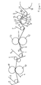
- the fibrous web 1 is transferred from a forming wire 2 of a former upstream of the press assembly for forming the paper machine to an upper, water-absorbing dewatering belt 3 of a first press nip of the press assembly. This transfer is supported by a looped by the dewatering belt 3, suctioned guide roll.
- This dewatering belt 3 leads the fibrous web 1 together with a lower water-absorbing dewatering belt 4 through the first press nip.
- the fibrous web 1 is still passed together via a transfer line from both dewatering belts 3,4, before the upper dewatering belt 3 is led away from the fibrous web 1.
- Both press gaps are elongated and are formed by an upper shoe press roll 11,13 and a lower cylindrical counter roll 10,12.
- the shoe press rollers 11,13 have a flexible roll shell, the one of Pressing element with concave pressing surface to the respective counter-roller 10,12 is pressed.
- the resulting, extended press nip allows for gentle, yet intensive dewatering.
- the upper dewatering belt 5 is led away from the fibrous web 1. This is not a problem since the fibrous web 1 adheres much more to the smooth transfer belt 6 than to the opposite dewatering belt 5.
- This transfer belt 7 leads the fibrous web 1 to another, lower, water-absorbing press belt 8 in the form of a press felt of a third press nip.
- This smoothing press nip is formed by a suction press roll 16 looped by the press belt 8 and an upper smoothing roll 15. In this case, the transfer of the fibrous web 1 takes place while the press belt 8 wraps around the suction press roll 16.
- the press belt 8 transfers the fibrous web 1 to an air-permeable belt 9 in the form of a drying wire of a following drying group of a dryer section of the machine, which is supported by a guide roller 17, which is looped around by the drying wire.
- the fibrous web 1 is guided for drying over heated drying cylinders 18, wherein the drying wire presses the fibrous web 1 against its lateral surface.
- the drainage bands 3, 4, 5, 7 of the press arrangement are not only water absorbent, but also permeable to air and designed as press felt.
- the air permeability allows the support of the railway transfer by suctioned guide roller 14th
- the transfer belt 6 should have not only a smooth contact surface with respect to the fibrous web 1, but also a hardness of about 50 P & J. This ensures a sufficient load capacity.
- the roughness Rz of the transfer belt 6 should be between 5 and 50 micrometers.
- the press belt 8 of the smoothing press nip should not only be water-absorbent and permeable to air, but also should be as smooth as possible. This supports the smoothing of the fibrous web 1 in the smoothing press nip and increases the adhesion of the fibrous web 1 to the press belt 8.
- a blowing device 20 which directs in particular during transfer blowing air between the smoothing roll 15 and the fibrous web 1.
- This smoothing roll 15 is provided to ensure sufficient smoothness with a ceramic coating.
- the suction press roll 16 has a plurality of suction zones 21, 22, 23, 24 arranged one behind the other in the web running direction 19.
- the holding zone 22 is intended only to guide the fibrous web 1 safely to the press nip.
- a post-zone 24 adjoins, which is intended to suck in the water thrown off this after the removal of the dewatering belt 8.
- a Wasserrrine 25 between the suction-pressure roller 16 and the expiring press belt. 8
- This press arrangement not only reduces the two-sidedness of the fibrous web 1 but also enables higher dry contents to be achieved at very high machine speeds.
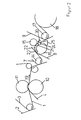
- This first press nip of the press arrangement is formed by an upper shoe press roll 11 and a cylindrical counter roll 10. Both press rolls 10, 11 each have a water-absorbing drainage band 3, 4.
- the lower dewatering belt 4 transfers the fibrous web 1 after the extended press nip and the routing of the upper dewatering belt 3 to the transfer belt 7. From this the fibrous web 1 passes to the press belt 8 of the smoothing press nip.
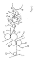
- the first press nip of the press assembly is formed by an upper suction press roll 26 and a lower shoe press roll 27. Also, both press rolls have their own water-absorbing drainage tape 28,29.
- the upper dewatering belt 28 takes over the fibrous web 1 not only from the forming wire 2, it also leads the fibrous web 1 after the extended press nip by a second press nip.
- This third press nip is formed by a shoe press roll 13 and the press roll 12 wrapped by a water-absorbing dewatering belt 5. This means that this press roller 12 is involved in the formation of two press nips, which makes the arrangement very compact.
- the transfer belt 6 then guides the fibrous web 1 until it is transferred to the transfer belt 7. From there it reaches the press belt 8 and through the smoothing press nip.
- the contact with the transfer belt 6 and the smoothing roller 15 results in an increased smoothness on both sides of the fibrous web 2. Furthermore, the multiplicity of press nips leads to a very high dewatering performance of the press arrangement.
Landscapes
- Paper (AREA)
Description
Die Erfindung betrifft eine Pressanordnung gemäß dem Oberbegriff des Anspruchs 1.The invention relates to a pressing arrangement according to the preamble of
Eine derartige Pressenanordnung ist aus der
Pressanordnungen bestehen aus einem oder mehreren Pressspalten, durch die, die Faserstoffbahn gemeinsam mit wasseraufnehmenden Pressfilzen geführt wird.Press arrangements consist of one or more press nips, through which the fibrous web is guided together with water-absorbing press felts.
Diese Pressfilze weisen eine relativ raue Kontaktfläche auf, was zu einer relativ hohen Rauhigkeit der Faserstoffbahn führt.These press felts have a relatively rough contact surface, resulting in a relatively high roughness of the fibrous web.
Im Interesse einer großen Entwässerungsleistung kommen dabei oft mehrere Pressspalte mit relativ hohen Pressdrücke zur Anwendung, was die Oberfläche der Faserstoffbahn stark beeinträchtigt.In the interest of a large dewatering performance are often several press nips with relatively high compression pressures used, which greatly affects the surface of the fibrous web.
Da die Faserstoffbahn im Bereich der Pressanordnung noch einen relativ hohen Feuchtegehalt aufweist, kann die Oberfläche der Faserstoffbahn auch relativ leicht beeinflusst werden.Since the fibrous web still has a relatively high moisture content in the area of the press arrangement, the surface of the fibrous web can also be influenced relatively easily.
Aus diesem Grund wurde auch vorgeschlagen, die Glätte der Faserstoffbahn über separate Glättvorrichtungen oder über den Kontakt mit glatten Presswalzen zu verbessern. Dabei stellt jedoch die starke Haftung der Faserstoffbahn an der glatten Pressfläche ein Problem für eine stabile Bahnführung dar.For this reason, it has also been proposed to improve the smoothness of the fibrous web via separate smoothing devices or via contact with smooth press rolls. However, the strong adhesion of the fibrous web to the smooth pressing surface poses a problem for a stable web guide.
Die Aufgabe der Erfindung ist es daher, die Bahnführung bei derartigen Glätt-Pressspalten mit möglicht geringem Aufwand zu verbessern.The object of the invention is therefore to improve the web guide in such smoothing press nips with the least possible effort.
Erfindungsgemäß wurde die Aufgabe durch die kennzeichnenden Merkmale des Anspruchs 1 gelöst.According to the invention the object has been solved by the characterizing features of
Der Unterdruck der Saug-Presswalze wirkt durch das Pressband auf die Faserstoffbahn ein und saugt diese an das Pressband.The negative pressure of the suction press roll acts on the fibrous web through the press belt and sucks it to the press belt.
Über das Pressband und/oder die Saug-Presswalze kann so einfach das aus der Faserstoffbahn gepresste Wasser aufgenommen werden.About the press belt and / or the suction press roll so easily pressed out of the fibrous web water can be absorbed.
Wegen des noch relativ hohen Feuchtegehaltes der Faserstoffbahn bewirkt der Kontakt mit der glatten Pressfläche bereits eine wesentliche Steigerung der Glätte auf dieser Seite der Faserstoffbahn.Because of the relatively high moisture content of the fibrous web contact with the smooth pressing surface already causes a significant increase in the smoothness on this side of the fibrous web.
Diese einseitige Glätteerzeugung kann bei bestimmten Produkten ausreichen.This one-sided smoothness production may be sufficient for certain products.
In vielen Fällen jedoch bildet sich in der Pressanordnung eine Zweiseitigkeit der Faserstoffbahn, insbesondere hinsichtlich Glanz und Glätte heraus. Um diese Zweiseitigkeit zu vermindern, kann die rauere Seite der Faserstoffbahn mit der glatten Pressfläche auf einfache Weise geglättet werden.In many cases, however, a two-sidedness of the fibrous web, in particular with regard to gloss and smoothness, forms in the press arrangement. To reduce this two-sidedness, the rougher side of the fibrous web can be smoothed with the smooth pressing surface in a simple manner.
Die glatte Pressfläche wird von einer glatten zylindrischen Glättwalze gebildet.The smooth pressing surface is formed by a smooth cylindrical smoothing roll.
Zur Gewährleistung einer ausreichend glatten Pressfläche kann es vorteilhaft sein, wenn die Glättwalze eine Beschichtung, vorzugsweise aus Keramik aufweist.To ensure a sufficiently smooth pressing surface, it may be advantageous if the smoothing roller has a coating, preferably of ceramic.
Außerdem kann die Weiterführung der Faserstoffbahn am Pressband auch nach dem Glätt-Pressspalt dadurch erleichtert werden, dass der Durchmesser der Glättwalze kleiner als der oder gleich dem Durchmesser der Saug-Presswalze ist.In addition, the continuation of the fibrous web on the press belt can be facilitated even after the smoothing press nip in that the diameter of the smoothing roll is smaller than or equal to the diameter of the suction press roll.
Um die Oberfläche der Faserstoffbahn im Glätt-Pressspalt durch den Kontakt mit dem Pressband nicht allzu stark zu beeinträchtigen, sollte das Pressband möglichst glatt ausgebildet sein und vorzugsweise Fasern mit höchstens 11 dtex oder eine Beschichtung mit Polymeren oder eine erhöhte Anzahl von Schmelzklebfasern auf der Kontaktseite zur Faserstoffbahn aufweisen.In order not to adversely affect the surface of the fibrous web in the smoothing press nip by the contact with the press belt, the press belt should be as smooth as possible and preferably fibers with at most 11 dtex or a coating of polymers or an increased number of hot melt adhesive fibers on the contact side Have fibrous web.
Damit die Faserstoffbahn möglichst umfassend an das Pressband gesaugt werden kann, sollte sich der Saugbereich der Saug-Presswalze zumindest über den Umschlingungsbereich des Pressbandes, vorzugsweise zumindest geringfügig darüber hinaus erstrecken. Zur Anpassung an die erforderliche Saugstärke besitzt die Saug-Presswalze mehrere, vorzugsweise in Bahnlaufrichtung hintereinander liegende Saugzonen.So that the fibrous web can be sucked as comprehensively as possible onto the press belt, the suction region of the suction press roll should extend at least over the wrap area of the press belt, preferably at least slightly beyond it. To adapt to the required suction strength, the suction press roll has a plurality of suction zones, preferably one behind the other in the web running direction.
Dabei ist es von Vorteil, wenn die Saug-Presswalze im Bereich des Glätt-Pressspaltes eine Hochvakuumzone besitzt, die sich vorzugsweise auch in Bahnlaufrichtung darüber hinaus, vorzugsweise bis zu 60 mm über den Glätt-Pressspalt hinaus erstreckt.It is advantageous if the suction press roll in the region of the smoothing press nip has a high vacuum zone, which preferably also extends in the web running direction beyond, preferably up to 60 mm beyond the smoothing press nip addition.
Der Unterdruck in der Hochvakuumzone sollte zwischen 10 und 60 kPa liegen. Die Stärke des Unterdrucks und die Erstreckung über den Glätt-Pressspalt hinaus gewährleisten die Weiterführung der Faserstoffbahn am Pressband nach dem Glätt-Pressspalt trotz der starken Haftung der Faserstoffbahn an der glatten Pressfläche.The vacuum in the high vacuum zone should be between 10 and 60 kPa. The strength of the negative pressure and the extent beyond the smoothing press gap ensure the continuation of the fibrous web on the press belt after the smoothing press nip despite the strong adhesion of the fibrous web to the smooth pressing surface.
Zur Begrenzung des Energieaufwandes genügt es, wenn der Unterdruck im Saugbereich der Saug-Presswalze außerhalb der Hochvakuumzone unter 30 kPa liegt.To limit the energy consumption, it is sufficient if the negative pressure in the suction region of the suction press roll outside the high vacuum zone is below 30 kPa.
Um eine geschlossenen Führung der Faserstoffbahn gewährleisten zu können, sollte das Pressband die Faserstoffbahn während der Umschlingung der Saug-Presswalze vorzugsweise von einem Übergabeband einer vorgelagerten Einheit übernehmen.In order to be able to ensure a closed guidance of the fibrous web, the press belt should preferably take over the fibrous web during the wrapping of the suction press roll from a transfer belt of an upstream unit.
Die geschlossene Führung der Faserstoffbahn, d.h. die Abstützung dieser an wenigstens einem Band oder einer Walze o. ä. führt zu einer sicheren Bahnführung und ermöglicht hohe Maschinengeschwindigkeiten.The closed guidance of the fibrous web, i. the support of this at least one band or a roller o. Ä. leads to a secure web guide and allows high machine speeds.
Daher wird die geschlossene Führung der Faserstoffbahn für die gesamte Pressanordnung angestrebt.Therefore, the closed leadership of the fibrous web is desired for the entire pressing arrangement.
Je nach Aufbau der Pressanordnung insbesondere der, dem Glätt-Pressspalt vorgelagerten Einheit, kann es vorteilhaft sein, wenn das Übergabeband als luftdurchlässiges und wasseraufnehmendes Entwässerungsband ausgebildet ist, welches vorzugsweise eine Presswalze eines vorgelagerten Pressspaltes umschlingt oder wenn das Übergabeband die Faserstoffbahn von einem glatten Transferband übernimmt, welches vorzugsweise eine Presswalze eines vorgelagerten Pressspaltes umschlingt.Depending on the structure of the pressing arrangement, in particular the upstream of the smoothing press nip unit, it may be advantageous if the transfer belt is designed as air-permeable and water-absorbing dewatering belt, which preferably wraps around a press roll of an upstream press nip or if the transfer belt takes over the fibrous web of a smooth transfer belt which preferably wraps around a press roll of an upstream press nip.
Um die Übernahme der Faserstoffbahn vom Transferband zu unterstützen, sollte das Übergabeband luftdurchlässig sein und während der Übernahme der Faserstoffbahn vom Transferband eine vorzugsweise besaugte Leitwalze umschlingen.In order to support the takeover of the fibrous web from the transfer belt, the transfer belt should be permeable to air and wrap around a preferably evacuated guide roller during the acquisition of the fibrous web from the transfer belt.
In beiden Fällen wird die vorgelagerte Einheit vorzugsweise von einem oder mehreren Pressspalten zur Entwässerung der Faserstoffbahn gebildet.In both cases, the upstream unit is preferably formed by one or more press nips for dewatering the fibrous web.
Um die Belastbarkeit des Transferbandes gewährleisten zu können, sollte dieses eine Härte von maximal 80, vorzugsweise maximal 50 P&J aufweisen. Zur Bildung einer möglichst glatten Kontaktfläche mit der Faserstoffbahn ist es von Vorteil, wenn das Transferband eine Rauhigkeit Rz zwischen 5 und 50 Mikrometer besitzt.In order to be able to ensure the load capacity of the transfer belt, this should have a maximum hardness of 80, preferably a maximum of 50 P & J. To form a As smooth as possible contact surface with the fibrous web, it is advantageous if the transfer ribbon has a roughness Rz between 5 and 50 microns.
Zur Ermöglichung eines Zugaufbaus wird die Saug-Presswalze vorzugsweise drehzahlgesteuert angetrieben.In order to allow a tensile structure, the suction press roll is preferably driven speed-controlled.
Auch die Glättwalze wird angetrieben. Bei der Glättwalze erfolgt der Antrieb im Normalbetrieb momentgesteuert. Zur Erleichterung bzw. Ermöglichung des Überführens der Faserstoffbahn wird der Glätt-Pressspalt während des Überführens der Faserstoffbahn geöffnet und die Glättwalze vorzugsweise drehzahlgesteuert angetrieben.The smoothing roller is also driven. In the smoothing roller, the drive is moment-controlled in normal operation. To facilitate or enable the transfer of the fibrous web of the smoothing press nip is opened during the transfer of the fibrous web and the smoothing roller is preferably driven speed controlled.
Falls das Übergabeband eine besaugte Leitwalze umschlingt, wie bei der Abnahme von dem Transferband, so ist es von Vorteil, wenn die Leitwalze des Übergabebandes zur Ermöglichung des Gleichlaufs mit der Saug-Presswalze vorzugsweise drehzahlgesteuert angetrieben wird.If the transfer belt wraps around an evacuated guide roll, as in the case of removal from the transfer belt, it is advantageous if the guide roll of the transfer belt is preferably speed-controlled in order to enable it to move with the suction press roll.
Zur Gewährleistung einer sicheren Bahnführung sollte sich im öffnenden Zwickel nach dem dritten Glätt-Pressspalt eine Blaseinrichtung befinden, welche insbesondere beim Überführen Blasluft zwischen die Glättwalze und die Faserstoffbahn richtet.To ensure safe web guidance, a blowing device should be located in the opening gusset after the third smoothing press nip, which in particular directs blowing air between the smoothing roll and the fibrous web when transferring.
Zur Unterstützung der Übernahme der Faserstoffbahn sollte die Saug-Presswalze im Bereich der Übernahme der Faserstoffbahn vom Übergabeband eine Überführzone aufweisen, deren Unterdruck vorzugsweise unter 30 kPa liegen kann.To support the takeover of the fibrous web, the suction press roll in the area of takeover of the fibrous web from the transfer belt should have a transfer zone whose negative pressure may preferably be below 30 kPa.
Die Führung der Faserstoffbahn zum Glätt-Pressspalt sollte dann eine, sich zwischen der Überführzone und der Hochvakuumzone erstreckende Haltezone übernehmen, deren Unterdruck vorzugsweise kleiner als 20 kPa ist.The guidance of the fibrous web to the smoothing press nip should then assume a, between the transfer zone and the high vacuum zone extending holding zone, the negative pressure is preferably less than 20 kPa.
Außerdem sollte sich an die Hochvakuumzone in Bahnlaufrichtung eine Nachzone anschließen. Diese Nachzone kann vom Pressband nach dessen Wegführung von der Saug-Presswalze abgeschleudertes Wasser aufnehmen.In addition, a post zone should follow the high vacuum zone in the web running direction. This post-zone can absorb thrown off the press belt after its removal from the suction press roll thrown off water.
Um dies noch zu unterstützen oder alternativ ist es von Vorteil, wenn sich im sich öffnenden Zwickel zwischen der Saug-Presswalze und dem Pressband eine Wasserauffangvorrichtung, vorzugsweise in Form einer Wasserrinne befindet.To support this or alternatively, it is advantageous if there is a water collecting device, preferably in the form of a gutter, in the opening gusset between the suction press roll and the press belt.
Zur Gewährleistung einer ausreichenden Entwässerung sollte dem Glätt-Pressspalt zumindest ein verlängerter Pressspalt vorgelagert sein.To ensure adequate drainage, the smoothing press nip should be preceded by at least one extended press nip.
Dabei sollte die Faserstoffbahn wegen des großen Wasseranfalls im Pressspalt mit beidseitig je einem wasseraufnehmenden Entwässerungsband durch den verlängerten Pressspalt geführt werden.Due to the large amount of water in the press nip, the fibrous web should be guided through the extended press nip with water-absorbing drainage tape on both sides.
Je nach Art der Faserstoffbahn kann es für eine ausreichende Entwässerung genügen, wenn dem Glätt-Pressspalt nur ein weiterer Pressspalt vorgelagert ist.Depending on the type of fibrous web, it may suffice for sufficient drainage if the smoothing press nip is preceded by only one further press nip.
In vielen Fällen ist es jedoch für die Entwässerung der Faserstoffbahn erforderlich, dass dem Glätt-Pressspalt mehrere Pressspalte vorgelagert sind.In many cases, however, it is necessary for the dewatering of the fibrous web that the Glätt press nip several press nips are upstream.
Dabei genügen mit Vorteil zwei oder drei dem Glätt-Pressspalt vorgelagerte Pressspalte.Advantageously, two or three press nips upstream of the smoothing press nip are sufficient.
Um die Faserstoffbahn möglichst beidseitig zu glätten, sollte zumindest einer der vorgelagerten Pressspalte eine glatte Pressfläche auf der, der glatten Pressfläche des Glätt-Pressspaltes gegenüberliegenden Seite der Faserstoffbahn haben.In order to smooth the fibrous web as possible on both sides, at least one of the upstream press nips should have a smooth pressing surface on the side of the fibrous web opposite the smooth press surface of the smoothing press nip.
Dabei kann es von Vorteil sein, wenn die glatte Pressfläche des vorgelagerten Pressspaltes vom Transferband gebildet wird.It may be advantageous if the smooth pressing surface of the upstream press nip is formed by the transfer belt.
Allgemein ist es für die Erhaltung der Oberflächeneigenschaften vorteilhaft, wenn der Glätt-Pressspalt der letzte Pressspalt der Pressanordnung ist.In general, it is advantageous for the maintenance of the surface properties if the smoothing press nip is the last press nip of the press arrangement.
Nachfolgend soll die Erfindung an mehreren Ausführungsbeispielen näher erläutert werden. In der beigefügten Zeichnung zeigt:
- Figur 1:
- einen schematischen Querschnitt durch eine Pressanordnung mit zwei vorgelagerten Pressspalten,
- Figur 2:
- mit einem vorgelagert Pressspalt und
- Figur 3:
- mit drei vorgelagerten Pressspalten.
- FIG. 1:
- a schematic cross section through a press arrangement with two upstream press nips,
- FIG. 2:
- with a pre-press nip and
- FIG. 3:
- with three upstream press nips.
In
Dieses Entwässerungsband 3 führt die Faserstoffbahn 1 gemeinsam mit einem unteren wasseraufnehmenden Entwässerungsband 4 durch den ersten Pressspalt.This
Nach diesem ersten Pressspalt wird die Faserstoffbahn 1 noch über eine Transferstrecke gemeinsam von beiden Entwässerungsbändern 3,4 geführt, bevor das obere Entwässerungsband 3 von der Faserstoffbahn 1 weggeleitet wird.After this first press nip, the
Das untere Entwässerungsband 4 übergibt anschließend die Faserstoffbahn 1 an ein oberes, wasseraufnehmendes Entwässerungsband 5 eines zweiten Pressspaltes. Durch diesen zweiten Pressspalt läuft die Faserstoffbahn 1 gemeinsam mit einem unteren glatten Transferband 6.The
Beide Pressspalte sind verlängert ausgeführt und werden von einer oberen Schuh-Presswalze 11,13 und einer unteren zylindrischen Gegenwalze 10,12 gebildet. Die Schuh-Presswalzen 11,13 besitzen einen flexiblen Walzenmantel, der von einem Anpresselement mit konkaver Pressfläche zur jeweiligen Gegenwalze 10,12 gedrückt wird.Both press gaps are elongated and are formed by an upper
Der dabei entstehende, verlängerte Pressspalt ermöglicht wegen der längeren Verweilzeit der Faserstoffbahn 1 eine schonende und dennoch intensive Entwässerung.Due to the longer residence time of the
Nach dem zweiten Pressspalt wird das obere Entwässerungsband 5 von der Faserstoffbahn 1 weggeführt. Dies ist unproblematisch, da die Faserstoffbahn 1 wesentlich stärker am glatten Transferband 6 als am gegenüberliegenden Entwässerungsband 5 haftet.After the second press nip, the
Von diesem Transferband 6 wird die Faserstoffbahn 1 im Anschluss an ein luftdurchlässiges Übergabeband 7 in Form eines markierungsarmen Trockensiebes übergeben. Diese Übergabe wird von einer, vom Übergabeband 7 umschlungenen und besaugten Leitwalze 14 unterstützt, indem der Unterdruck dieser Leitwalze 14 die Faserstoffbahn 1 an das Übergabeband 7 saugt.From this
Dieses Übergabeband 7 führt die Faserstoffbahn 1 an ein weiteres, unteres, wasseraufnehmendes Pressband 8 in Form eines Pressfilzes eines dritten Pressspaltes. Dieser Glätt-Pressspalt wird von einer vom Pressband 8 umschlungenen Saug-Presswalze 16 und einer oberen Glättwalze 15 gebildet. Dabei erfolgt die Übergabe der Faserstoffbahn 1 während das Pressband 8 die Saug-Presswalze 16 umschlingt.This
Nach diesem Glätt-Pressspalt übergibt das Pressband 8 die Faserstoffbahn 1 an ein luftdurchlässiges Band 9 in Form eins Trockensiebes einer folgenden Trockengruppe einer Trockenpartie der Maschine, was von einer, vom Trockensieb umschlungenen, besaugten Leitwalze 17 unterstützt wird.After this smoothing press nip, the press belt 8 transfers the
In der Trockengruppe wird die Faserstoffbahn 1 zur Trocknung über beheizte Trockenzylinder 18 geführt, wobei das Trockensieb die Faserstoffbahn 1 gegen deren Mantelfläche drückt.In the drying group, the
Auf diese Weise wird die Faserstoffbahn 1 innerhalb der Pressanordnung ständig von einem Band gestützt, so dass die Bahnführung wesentlich stabiler und sicherer wird, was wesentlich höhere Maschinengeschwindigkeiten erlaubt.In this way, the
Durch den Kontakt mit dem glatten Transferband 6 und der Glättwalze 15 kommt es zur beidseitigen Glättung der Faserstoffbahn 1. Dies hat eine wesentliche Verminderung der Rauhigkeit der Faserstoffbahn 1 zur Folge.The contact with the
Die Entwässerungsbänder 3,4,5,7 der Pressanordnung sind nicht nur wasseraufnehmend, sondern auch luftdurchlässig und als Pressfilz ausgebildet. Die Luftdurchlässigkeit erlaubt dabei die Unterstützung der Bahnübernahme durch besaugte Leitwalze 14.The
Das Transferband 6 sollte nicht nur eine glatte Kontaktfläche hinsichtlich der Faserstoffbahn 1, sondern auch eine Härte von ca. 50 P&J aufweisen. Dies gewährleistet eine ausreichende Belastbarkeit. Die Rauhigkeit Rz des Transferbandes 6 sollte zwischen 5 und 50 Mikrometer liegen.The
Das Pressband 8 des Glätt-Pressspaltes sollte nicht nur wasseraufnehmend und luftdurchlässig, sondern auch möglichst glatt sein. Dies unterstützt die Glättung der Faserstoffbahn 1 im Glätt-Pressspalt und verstärkt die Haftung der Faserstoffbahn 1 am Pressband 8.The press belt 8 of the smoothing press nip should not only be water-absorbent and permeable to air, but also should be as smooth as possible. This supports the smoothing of the
Hierzu sollte das Pressband 8 Fasern mit höchstens 11 dtex oder eine Beschichtung mit Polymeren oder eine erhöhte Anzahl von Schmelzklebfasern auf der Kontaktseite zur Faserstoffbahn 1 aufweisen.For this purpose, the press belt should have 8 fibers with at most 11 dtex or a coating with polymers or an increased number of hot melt adhesive fibers on the contact side to the
Um die Führung der Faserstoffbahn 1 am Pressband 8 nach dem Glätt-Pressspalt zu unterstützen, befindet sich im Zwickel des auslaufenden Pressspaltes eine Blaseinrichtung 20, welche insbesondere beim Überführen Blasluft zwischen die Glättwalze 15 und die Faserstoffbahn 1 richtet.In order to support the guidance of the
Dies ist nötig, weil die Faserstoffbahn 1 eine relativ starke Haftung an der glatten Glättwalze 15 aufweist.This is necessary because the
Diese Glättwalze 15 ist zur Gewährleistung einer ausreichenden Glätte mit einer Keramikbeschichtung versehen.This smoothing
Die Saug-Presswalze 16 besitzt mehrere in Bahnlaufrichtung 19 hintereinander angeordnete Saugzonen 21,22,23,24.The
Dabei befindet sich im und in Bahnlaufrichtung 19 darüber hinaus eine Hochvakuumzone 21 mit einem Unterdruck zwischen 30 und 60 kPa. Dieser hohe Unterdruck unterstützt die Entwässerung und die Haftung der Faserstoffbahn 1 am Pressband 8.In addition, there is a high-
Alle anderen Saugzonen 22,23,24 weisen einen Unterdruck von weniger als 30 kPa auf.All
Während die in Bahnlaufrichtung 19 erste Übernahmezone 23 die Übergabe der Faserstoffbahn 1 vom Transferband 6 an das Pressband 8 unterstützt, soll die Haltzone 22 die Faserstoffbahn 1 lediglich sicher zum Pressspalt führen.While the
Nach der Hochvakuumzone 21 schließt sich eine Nachzone 24 an, die das nach der Wegführung des Entwässerungsbandes 8 von diesem abgeschleuderten Wasser ansaugen soll. Zur Aufnahme dieses abgeschleuderten Wassers befindet sich auch eine Wasserrrine 25 zwischen der Saug-Presswalze 16 und dem ablaufenden Pressband 8.After the high-
Um das Überführen der Faserstoffbahn 1 zu verbessern, wird die Glättwalze 15 abgehoben und während dieser Zeit drehzahlgesteuert angetrieben. Dies erleichtert das nachfolgende Schließen des Pressspaltes mit der ebenfalls drehzahlgesteuert angetriebenen Saug-Presswalze 16.In order to improve the transfer of the
Im Normalbetrieb wird die Glättwalze 15 jedoch momentgesteuert angetrieben.In normal operation, however, the smoothing
Um einen Gleichlauf zwischen der Leitwalze 14 des Übergabebandes 7 mit der Saug-Presswalze 16 zu ermöglichen, wird diese Leitwalze 14 drehzahlgesteuert angetrieben.In order to enable a synchronization between the
Diese Pressanordnung vermindert nicht nur die Zweiseitigkeit der Faserstoffbahn 1 sondern sie ermöglicht auch das Erreichen höherer Trockengehalte bei sehr hohen Maschinengeschwindigkeiten.This press arrangement not only reduces the two-sidedness of the
Hiervon unterscheidet sich die Anordnung gemäß
Dieser erste Pressspalt der Pressanordnung wird von einer oberen Schuh-Presswalze 11 und einer zylindrischen Gegenwalze 10 gebildet. Beide Presswalzen 10,11 besitzen je ein wasseraufnehmendes Entwässerungsband 3,4.This first press nip of the press arrangement is formed by an upper
Während das obere Entwässerungsband 3 wie in
Diese Anordnung ist mit erheblich vermindertem Aufwand verbunden und kann bereits viele Ansprüche an die Faserstoffbahn 1 erfüllen.This arrangement is associated with considerably reduced effort and can already meet many demands on the
Bei der in
Jedoch übernimmt hier das obere Entwässerungsband 28 die Faserstoffbahn 1 nicht nur vom Formersieb 2, es führt die Faserstoffbahn 1 nach dem verlängerten Pressspalt auch durch einen zweiten Pressspalt.However, here the
Dieser zweite Pressspalt wird von einer zylindrischen Presswalze 12, welche von einem glatten Transferband 6 umschlungen ist, und der Saug-Presswalze 26 gebildet.This second press nip is formed by a
Der Unterdruck der Saugpresswalze 26 unterstützt hier nicht nur die Wasserabfuhr im ersten Pressspalt sondern auch die Haftung der Faserstoffbahn 1 am oberen Entwässerungsband 28 bis zum zweiten Pressspalt.The negative pressure of the
Nach dem zweiten Pressspalt läuft die Faserstoffbahn 1 wegen der stärkeren Haftung gemeinsam mit dem Transferband 6 bis zu einem dritten Pressspalt.After the second press nip, the
Dieser dritte Pressspalt wird von einer von einem wasseraufnehmenden Entwässerungsband 5 umschlungenen Schuh-Presswalze 13 und der Presswalze 12 gebildet. Dies bedeutet, dass diese Presswalze 12 an der Bildung von zwei Pressspalten beteiligt ist, was die Anordnung sehr kompakt macht.This third press nip is formed by a
Das Transferband 6 führt die Faserstoffbahn 1 anschließend bis zur Übergabe an das Übergabeband 7. Von dort gelangt sie an das Pressband 8 und durch den Glätt-Pressspalt.The
Durch den Kontakt mit dem Transferband 6 und der Glättwalze 15 ergibt sich auf beiden Seiten der Faserstoffbahn 2 eine erhöhte Glätte. Des Weiteren führt die Vielzahl von Pressspalten zu einer sehr hohen Entwässerungsleistung der Pressanordnung.The contact with the
Eine vorteilhafte Kombination des Glätt-Pressspaltes ist nicht auf die hier dargestellten Anordnungen begrenzt.An advantageous combination of the smoothing press nip is not limited to the arrangements shown here.
Claims (33)
- Press arrangement for dewatering a paper, board or other fibrous web (1) in a machine for producing and/or finishing the same, having at least one smoothing press nip, through which the fibrous web (1) runs together with a water-absorbing, air-permeable press belt (8) and the pressing surface of which, arranged on the side of the fibrous web (1) that is opposite the press belt (8), is of smooth construction, the pressing surface opposite the smooth pressing surface being formed by a suction press roll (16), the suction press roll (16) being driven and having a plurality of suction zones (21, 22, 23, 24), and the smooth pressing surface being formed by a smooth cylindrical driven smoothing roll (15), characterized in that
the suction press roll (16) is driven under speed control, the smoothing roll (15) is driven under torque control in normal operation, and the smoothing nip is opened during the transfer of the fibrous web (1). - Press arrangement according to Claim 1, characterized in that
the smoothing roll (15) has a coating, preferably of ceramic. - Press arrangement according to Claim 1 or 2, characterized in that
the diameter of the smoothing roll (15) is less than or equal to the diameter of the suction press roll (16). - Press arrangement according to one of the preceding claims,
characterized in that
the press belt (8) has fibres with at most 11 dtex or a coating with polymers on the contact side of the fibrous web. - Press arrangement according to one of the preceding claims,
characterized in that
the suction region of the suction press roll (16) extends at least over the wrap region of the press belt (8). - Press arrangement according to one of the preceding claims,
characterized in that
the suction press roll (16) has a plurality of suction zones (21, 22, 23, 24) located one after another in the web running direction (19). - Press arrangement according to Claim 6, characterized in that
in the region of the smoothing press nip, the suction press roll (16) has a high-vacuum zone (21), which preferably also extends beyond the former in the web running direction (19). - Press arrangement according to Claim 7, characterized in that
the high-vacuum zone (21) extends up to 60 mm beyond the smoothing press nip. - Press arrangement according to Claim 7 or 8, characterized in that
the negative pressure in the high-vacuum zone (21) lies between 10 and 60 kPa. - Press arrangement according to one of Claims 7 to 9,
characterized in that
the negative pressure in the suction region of the suction press roll (16) outside the high-vacuum zone (21) lies below 30 kPa. - Press arrangement according to one of the preceding claims,
characterized in that
the press belt (8) picks up the fibrous web (1) during the wrap around the suction press roll (16), preferably from a transfer belt (7) of an upstream unit. - Press arrangement according to Claim 11, characterized in that
the transfer belt (7) is constructed as an air-permeable and water-absorbent dewatering belt, which preferably wraps around a press roll of an upstream press nip. - Press arrangement according to Claim 11, characterized in that
the transfer belt (7) picks up the fibrous web (1) from a smooth transfer belt (6), which preferably wraps around a press roll (12) of an upstream press nip. - Press arrangement according to Claim 13, characterized in that
the transfer belt (7) is air-permeable and, during the transfer of the fibrous web (1) from the transfer belt (6), wraps around a preferably evacuated guide roll (14). - Press arrangement according to one of Claims 11 to 14,
characterized in that
the upstream unit is formed by one or more press nips for dewatering the fibrous web (1). - Press arrangement according to one of Claims 13 to 15,
characterized in that
the transfer belt (6) has a hardness of at most 80, preferably at most 50, P&J. - Press arrangement according to one of Claims 13 to 16,
characterized in that
the transfer belt (6) has a roughness Rz between 5 and 50 micrometres. - Press arrangement according to one of the preceding claims,
characterized in that
during the transfer of the fibrous web (1), the smoothing roll (15) is driven under speed control. - Press arrangement according to one of Claims 14 to 18,
characterized in that
the guide roll (14) of the transfer belt (7) is preferably driven under speed control. - Press arrangement according to one of the preceding claims,
characterized in that
in the opening pocket after the smoothing press nip there is a blowing device (20) which, in particular during the transfer, directs blown air between the smoothing roll (15) and the fibrous web (1). - Press arrangement according to one of Claims 11 to 20,
characterized in that
in the region of the transfer of the fibrous web (1) from the transfer belt (7), the suction press roll (16) has a transfer zone (23), the negative pressure of which preferably lies below 30 kPa. - Press arrangement according to Claim 7 and Claim 21,
characterized in that
between the transfer zone (23) and the high-vacuum zone (21) there is a holding zone (22), the negative pressure of which is preferably less than 20 kPa. - Press arrangement according to Claim 22, characterized in that
the high-vacuum zone (21) is followed by an afterzone (24) in the web running direction (19). - Press arrangement according to one of the preceding claims,
characterized in that
in the opening pocket between the suction press roll (16) and the press belt (8) there is a water collecting apparatus (25), preferably in the form of a water trough. - Press arrangement according to one of the preceding claims,
characterized in that
at least one extended press nip is located upstream of the smoothing press nip. - Press arrangement according to Claim 25, characterized in that
the fibrous web is led through the extended press nip with a respective water-absorbing dewatering belt (3, 4, 28, 29) on both sides. - Press arrangement according to one of the preceding claims,
characterized in that
only one further press nip is located upstream of the smoothing press nip. - Press arrangement according to one of Claims 1 to 26,
characterized in that
a plurality of press nips are located upstream of the smoothing press nip. - Press arrangement according to Claim 28, characterized in that
two further press nips are located upstream of the smoothing press nip. - Press arrangement according to Claim 28, characterized in that
three further press nips are located upstream of the smoothing press nip. - Press arrangement according to one of Claims 27 to 30,
characterized in that
at least one of the upstream press nips has a smooth pressing surface on the side of the fibrous web (1) opposite the smooth pressing surface of the smoothing press nip. - Press arrangement according to Claim 13 and Claim 31,
characterized in that
the smooth pressing surface of the upstream press nip is formed by the transfer belt (6). - Press arrangement according to one of the preceding claims,
characterized in that
the smoothing press nip is the last press nip of the press arrangement.
Applications Claiming Priority (1)
| Application Number | Priority Date | Filing Date | Title |
|---|---|---|---|
| DE200510050281 DE102005050281A1 (en) | 2005-10-20 | 2005-10-20 | Press arrangement |
Publications (2)
| Publication Number | Publication Date |
|---|---|
| EP1777342A1 EP1777342A1 (en) | 2007-04-25 |
| EP1777342B1 true EP1777342B1 (en) | 2014-03-19 |
Family
ID=37499418
Family Applications (1)
| Application Number | Title | Priority Date | Filing Date |
|---|---|---|---|
| EP20060121951 Active EP1777342B1 (en) | 2005-10-20 | 2006-10-09 | Pressing arrangement |
Country Status (2)
| Country | Link |
|---|---|
| EP (1) | EP1777342B1 (en) |
| DE (1) | DE102005050281A1 (en) |
Families Citing this family (3)
| Publication number | Priority date | Publication date | Assignee | Title |
|---|---|---|---|---|
| DE102008000151A1 (en) * | 2008-01-25 | 2009-07-30 | Voith Patent Gmbh | Device for producing and / or treating a fibrous web |
| DE102009047470A1 (en) * | 2009-12-03 | 2011-06-09 | Voith Patent Gmbh | Apparatus for treating a running paper, cardboard or other fibrous web |
| DE102016209780A1 (en) * | 2016-06-03 | 2017-12-07 | Voith Patent Gmbh | press section |
Family Cites Families (11)
| Publication number | Priority date | Publication date | Assignee | Title |
|---|---|---|---|---|
| DE684680C (en) * | 1935-06-21 | 1939-12-02 | William Hulse Millspaugh | Fourdrinier paper machine |
| GB458758A (en) * | 1935-06-21 | 1936-12-21 | William Hulse Millspaugh | Improvements in or relating to paper making machines |
| US2959222A (en) * | 1957-06-05 | 1960-11-08 | Beloit Iron Works | Pickup and press section |
| FI803021A (en) * | 1980-09-25 | 1982-03-26 | Valmet Oy | FOERFARANDE I PRESSDELEN I EN PAPPERSMASKIN |
| US4483745A (en) * | 1982-09-29 | 1984-11-20 | Beloit Corporation | Method and apparatus of sheet transfer using a nonporous smooth surfaced belt |
| US5298124A (en) * | 1992-06-11 | 1994-03-29 | Albany International Corp. | Transfer belt in a press nip closed draw transfer |
| DE10137527A1 (en) * | 2001-08-01 | 2003-02-13 | Voith Paper Patent Gmbh | Rotogravure paper manufacturing assembly has additional press slits |
| DE10159115A1 (en) * | 2001-12-01 | 2003-06-18 | Voith Paper Patent Gmbh | press section |
| FI20020804A0 (en) * | 2002-04-26 | 2002-04-26 | Tamfelt Oyj Abp | Arrangement in the paper machine press section |
| DE10226825A1 (en) * | 2002-06-15 | 2003-12-24 | Voith Paper Patent Gmbh | Press arrangement |
| FI116400B (en) * | 2002-11-19 | 2005-11-15 | Metso Paper Inc | Press section in a paper or cardboard machine |
-
2005
- 2005-10-20 DE DE200510050281 patent/DE102005050281A1/en not_active Withdrawn
-
2006
- 2006-10-09 EP EP20060121951 patent/EP1777342B1/en active Active
Also Published As
| Publication number | Publication date |
|---|---|
| EP1777342A1 (en) | 2007-04-25 |
| DE102005050281A1 (en) | 2007-04-26 |
Similar Documents
| Publication | Publication Date | Title |
|---|---|---|
| EP1072721B1 (en) | Paper machine | |
| DE102018119686A1 (en) | paper machine | |
| EP1316641B1 (en) | Press section | |
| EP1777342B1 (en) | Pressing arrangement | |
| EP1478806B1 (en) | Smoothing device | |
| EP3833816B1 (en) | Pressing arrangement | |
| EP1777340B1 (en) | Pressing arrangement | |
| DE102004050593A1 (en) | Press arrangement | |
| EP1838919B1 (en) | Pressing arrangement | |
| DE19956752A1 (en) | Drive control for the movement of a fiber web through papermaking or tissue or cardboard production sets the difference speed between delivery and pick-up transfer units according to the web moisture content | |
| DE10137095A1 (en) | Machine for the production of a fibrous web | |
| EP1743974B1 (en) | Press section | |
| WO2009092477A1 (en) | Device for producing and/or processing a fiber material web | |
| DE102005048928A1 (en) | Press for dewatering and smoothing a paper web comprises an extended press nip and a calender nip between which the web runs with no open draw | |
| DE29923284U1 (en) | Paper machine | |
| DE10132652A1 (en) | Press assembly, for wet lightweight paper/cardboard webs, has a single shoe press with an extended press nip and continuous blankets flanking the web with a drive for at least one blanket | |
| DE102008040612A1 (en) | Press arrangement for drainage of paper, cardboard, tissue or another fibrous material course in machine for its production or refinement, has press gap formed by two press rollers and smoothing band | |
| EP1460170A1 (en) | Press arrangement | |
| DE102005009858A1 (en) | paper machine | |
| EP1775377A1 (en) | Pressing arrangement | |
| DE10161989A1 (en) | Web transfer between pairs of continuous belts, at the press section of a papermaking production/finishing machine, passes the web between two belts through a roller press gap before the transfer | |
| DE19724218A1 (en) | Paper=making machine press section | |
| DE20122810U1 (en) | press section | |
| EP1770204A2 (en) | Pressing arrangement | |
| EP1347097A2 (en) | Pressing arrangement |
Legal Events
| Date | Code | Title | Description |
|---|---|---|---|
| PUAI | Public reference made under article 153(3) epc to a published international application that has entered the european phase |
Free format text: ORIGINAL CODE: 0009012 |
|
| AK | Designated contracting states |
Kind code of ref document: A1 Designated state(s): AT BE BG CH CY CZ DE DK EE ES FI FR GB GR HU IE IS IT LI LT LU LV MC NL PL PT RO SE SI SK TR |
|
| AX | Request for extension of the european patent |
Extension state: AL BA HR MK YU |
|
| 17P | Request for examination filed |
Effective date: 20071025 |
|
| AKX | Designation fees paid |
Designated state(s): AT BE BG CH CY CZ DE DK EE ES FI FR GB GR HU IE IS IT LI LT LU LV MC NL PL PT RO SE SI SK TR |
|
| 17Q | First examination report despatched |
Effective date: 20130314 |
|
| GRAP | Despatch of communication of intention to grant a patent |
Free format text: ORIGINAL CODE: EPIDOSNIGR1 |
|
| INTG | Intention to grant announced |
Effective date: 20131014 |
|
| GRAS | Grant fee paid |
Free format text: ORIGINAL CODE: EPIDOSNIGR3 |
|
| GRAA | (expected) grant |
Free format text: ORIGINAL CODE: 0009210 |
|
| AK | Designated contracting states |
Kind code of ref document: B1 Designated state(s): AT BE BG CH CY CZ DE DK EE ES FI FR GB GR HU IE IS IT LI LT LU LV MC NL PL PT RO SE SI SK TR |
|
| REG | Reference to a national code |
Ref country code: GB Ref legal event code: FG4D Free format text: NOT ENGLISH |
|
| REG | Reference to a national code |
Ref country code: CH Ref legal event code: EP |
|
| REG | Reference to a national code |
Ref country code: IE Ref legal event code: FG4D Free format text: LANGUAGE OF EP DOCUMENT: GERMAN |
|
| REG | Reference to a national code |
Ref country code: AT Ref legal event code: REF Ref document number: 657786 Country of ref document: AT Kind code of ref document: T Effective date: 20140415 |
|
| REG | Reference to a national code |
Ref country code: DE Ref legal event code: R096 Ref document number: 502006013610 Country of ref document: DE Effective date: 20140424 |
|
| PG25 | Lapsed in a contracting state [announced via postgrant information from national office to epo] |
Ref country code: LT Free format text: LAPSE BECAUSE OF FAILURE TO SUBMIT A TRANSLATION OF THE DESCRIPTION OR TO PAY THE FEE WITHIN THE PRESCRIBED TIME-LIMIT Effective date: 20140319 |
|
| REG | Reference to a national code |
Ref country code: NL Ref legal event code: VDEP Effective date: 20140319 |
|
| REG | Reference to a national code |
Ref country code: LT Ref legal event code: MG4D |
|
| PG25 | Lapsed in a contracting state [announced via postgrant information from national office to epo] |
Ref country code: CY Free format text: LAPSE BECAUSE OF FAILURE TO SUBMIT A TRANSLATION OF THE DESCRIPTION OR TO PAY THE FEE WITHIN THE PRESCRIBED TIME-LIMIT Effective date: 20140319 Ref country code: SE Free format text: LAPSE BECAUSE OF FAILURE TO SUBMIT A TRANSLATION OF THE DESCRIPTION OR TO PAY THE FEE WITHIN THE PRESCRIBED TIME-LIMIT Effective date: 20140319 |
|
| PG25 | Lapsed in a contracting state [announced via postgrant information from national office to epo] |
Ref country code: LV Free format text: LAPSE BECAUSE OF FAILURE TO SUBMIT A TRANSLATION OF THE DESCRIPTION OR TO PAY THE FEE WITHIN THE PRESCRIBED TIME-LIMIT Effective date: 20140319 |
|
| PG25 | Lapsed in a contracting state [announced via postgrant information from national office to epo] |
Ref country code: BG Free format text: LAPSE BECAUSE OF FAILURE TO SUBMIT A TRANSLATION OF THE DESCRIPTION OR TO PAY THE FEE WITHIN THE PRESCRIBED TIME-LIMIT Effective date: 20140619 Ref country code: NL Free format text: LAPSE BECAUSE OF FAILURE TO SUBMIT A TRANSLATION OF THE DESCRIPTION OR TO PAY THE FEE WITHIN THE PRESCRIBED TIME-LIMIT Effective date: 20140319 Ref country code: CZ Free format text: LAPSE BECAUSE OF FAILURE TO SUBMIT A TRANSLATION OF THE DESCRIPTION OR TO PAY THE FEE WITHIN THE PRESCRIBED TIME-LIMIT Effective date: 20140319 Ref country code: RO Free format text: LAPSE BECAUSE OF FAILURE TO SUBMIT A TRANSLATION OF THE DESCRIPTION OR TO PAY THE FEE WITHIN THE PRESCRIBED TIME-LIMIT Effective date: 20140319 Ref country code: EE Free format text: LAPSE BECAUSE OF FAILURE TO SUBMIT A TRANSLATION OF THE DESCRIPTION OR TO PAY THE FEE WITHIN THE PRESCRIBED TIME-LIMIT Effective date: 20140319 Ref country code: IS Free format text: LAPSE BECAUSE OF FAILURE TO SUBMIT A TRANSLATION OF THE DESCRIPTION OR TO PAY THE FEE WITHIN THE PRESCRIBED TIME-LIMIT Effective date: 20140719 |
|
| PG25 | Lapsed in a contracting state [announced via postgrant information from national office to epo] |
Ref country code: PL Free format text: LAPSE BECAUSE OF FAILURE TO SUBMIT A TRANSLATION OF THE DESCRIPTION OR TO PAY THE FEE WITHIN THE PRESCRIBED TIME-LIMIT Effective date: 20140319 Ref country code: SK Free format text: LAPSE BECAUSE OF FAILURE TO SUBMIT A TRANSLATION OF THE DESCRIPTION OR TO PAY THE FEE WITHIN THE PRESCRIBED TIME-LIMIT Effective date: 20140319 Ref country code: ES Free format text: LAPSE BECAUSE OF FAILURE TO SUBMIT A TRANSLATION OF THE DESCRIPTION OR TO PAY THE FEE WITHIN THE PRESCRIBED TIME-LIMIT Effective date: 20140319 |
|
| REG | Reference to a national code |
Ref country code: DE Ref legal event code: R097 Ref document number: 502006013610 Country of ref document: DE |
|
| PG25 | Lapsed in a contracting state [announced via postgrant information from national office to epo] |
Ref country code: PT Free format text: LAPSE BECAUSE OF FAILURE TO SUBMIT A TRANSLATION OF THE DESCRIPTION OR TO PAY THE FEE WITHIN THE PRESCRIBED TIME-LIMIT Effective date: 20140721 |
|
| PLBE | No opposition filed within time limit |
Free format text: ORIGINAL CODE: 0009261 |
|
| STAA | Information on the status of an ep patent application or granted ep patent |
Free format text: STATUS: NO OPPOSITION FILED WITHIN TIME LIMIT |
|
| PG25 | Lapsed in a contracting state [announced via postgrant information from national office to epo] |
Ref country code: DK Free format text: LAPSE BECAUSE OF FAILURE TO SUBMIT A TRANSLATION OF THE DESCRIPTION OR TO PAY THE FEE WITHIN THE PRESCRIBED TIME-LIMIT Effective date: 20140319 |
|
| 26N | No opposition filed |
Effective date: 20141222 |
|
| PG25 | Lapsed in a contracting state [announced via postgrant information from national office to epo] |
Ref country code: IT Free format text: LAPSE BECAUSE OF FAILURE TO SUBMIT A TRANSLATION OF THE DESCRIPTION OR TO PAY THE FEE WITHIN THE PRESCRIBED TIME-LIMIT Effective date: 20140319 |
|
| REG | Reference to a national code |
Ref country code: DE Ref legal event code: R097 Ref document number: 502006013610 Country of ref document: DE Effective date: 20141222 |
|
| PG25 | Lapsed in a contracting state [announced via postgrant information from national office to epo] |
Ref country code: LU Free format text: LAPSE BECAUSE OF FAILURE TO SUBMIT A TRANSLATION OF THE DESCRIPTION OR TO PAY THE FEE WITHIN THE PRESCRIBED TIME-LIMIT Effective date: 20141009 Ref country code: MC Free format text: LAPSE BECAUSE OF FAILURE TO SUBMIT A TRANSLATION OF THE DESCRIPTION OR TO PAY THE FEE WITHIN THE PRESCRIBED TIME-LIMIT Effective date: 20140319 |
|
| REG | Reference to a national code |
Ref country code: CH Ref legal event code: PL |
|
| GBPC | Gb: european patent ceased through non-payment of renewal fee |
Effective date: 20141009 |
|
| PG25 | Lapsed in a contracting state [announced via postgrant information from national office to epo] |
Ref country code: BE Free format text: LAPSE BECAUSE OF NON-PAYMENT OF DUE FEES Effective date: 20141031 |
|
| REG | Reference to a national code |
Ref country code: IE Ref legal event code: MM4A |
|
| PG25 | Lapsed in a contracting state [announced via postgrant information from national office to epo] |
Ref country code: SI Free format text: LAPSE BECAUSE OF FAILURE TO SUBMIT A TRANSLATION OF THE DESCRIPTION OR TO PAY THE FEE WITHIN THE PRESCRIBED TIME-LIMIT Effective date: 20140319 Ref country code: GB Free format text: LAPSE BECAUSE OF NON-PAYMENT OF DUE FEES Effective date: 20141009 Ref country code: LI Free format text: LAPSE BECAUSE OF NON-PAYMENT OF DUE FEES Effective date: 20141031 Ref country code: CH Free format text: LAPSE BECAUSE OF NON-PAYMENT OF DUE FEES Effective date: 20141031 |
|
| REG | Reference to a national code |
Ref country code: FR Ref legal event code: ST Effective date: 20150630 |
|
| PG25 | Lapsed in a contracting state [announced via postgrant information from national office to epo] |
Ref country code: FR Free format text: LAPSE BECAUSE OF NON-PAYMENT OF DUE FEES Effective date: 20141031 |
|
| PG25 | Lapsed in a contracting state [announced via postgrant information from national office to epo] |
Ref country code: IE Free format text: LAPSE BECAUSE OF NON-PAYMENT OF DUE FEES Effective date: 20141009 |
|
| PG25 | Lapsed in a contracting state [announced via postgrant information from national office to epo] |
Ref country code: GR Free format text: LAPSE BECAUSE OF FAILURE TO SUBMIT A TRANSLATION OF THE DESCRIPTION OR TO PAY THE FEE WITHIN THE PRESCRIBED TIME-LIMIT Effective date: 20140620 |
|
| PG25 | Lapsed in a contracting state [announced via postgrant information from national office to epo] |
Ref country code: TR Free format text: LAPSE BECAUSE OF FAILURE TO SUBMIT A TRANSLATION OF THE DESCRIPTION OR TO PAY THE FEE WITHIN THE PRESCRIBED TIME-LIMIT Effective date: 20140319 Ref country code: HU Free format text: LAPSE BECAUSE OF FAILURE TO SUBMIT A TRANSLATION OF THE DESCRIPTION OR TO PAY THE FEE WITHIN THE PRESCRIBED TIME-LIMIT; INVALID AB INITIO Effective date: 20061009 |
|
| PGFP | Annual fee paid to national office [announced via postgrant information from national office to epo] |
Ref country code: FI Payment date: 20231019 Year of fee payment: 18 Ref country code: DE Payment date: 20231020 Year of fee payment: 18 Ref country code: AT Payment date: 20231020 Year of fee payment: 18 |