EP1776058B1 - Dental light device having an improved heat sink - Google Patents
Dental light device having an improved heat sink Download PDFInfo
- Publication number
- EP1776058B1 EP1776058B1 EP05769322.8A EP05769322A EP1776058B1 EP 1776058 B1 EP1776058 B1 EP 1776058B1 EP 05769322 A EP05769322 A EP 05769322A EP 1776058 B1 EP1776058 B1 EP 1776058B1
- Authority
- EP
- European Patent Office
- Prior art keywords
- dental curing
- light
- phase change
- hand held
- change material
- Prior art date
- Legal status (The legal status is an assumption and is not a legal conclusion. Google has not performed a legal analysis and makes no representation as to the accuracy of the status listed.)
- Active
Links
Images


Classifications
-
- A—HUMAN NECESSITIES
- A61—MEDICAL OR VETERINARY SCIENCE; HYGIENE
- A61C—DENTISTRY; APPARATUS OR METHODS FOR ORAL OR DENTAL HYGIENE
- A61C19/00—Dental auxiliary appliances
- A61C19/003—Apparatus for curing resins by radiation
- A61C19/004—Hand-held apparatus, e.g. guns
-
- A—HUMAN NECESSITIES
- A61—MEDICAL OR VETERINARY SCIENCE; HYGIENE
- A61K—PREPARATIONS FOR MEDICAL, DENTAL OR TOILETRY PURPOSES
- A61K6/00—Preparations for dentistry
- A61K6/80—Preparations for artificial teeth, for filling teeth or for capping teeth
- A61K6/849—Preparations for artificial teeth, for filling teeth or for capping teeth comprising inorganic cements
- A61K6/864—Phosphate cements
-
- A—HUMAN NECESSITIES
- A61—MEDICAL OR VETERINARY SCIENCE; HYGIENE
- A61K—PREPARATIONS FOR MEDICAL, DENTAL OR TOILETRY PURPOSES
- A61K6/00—Preparations for dentistry
- A61K6/80—Preparations for artificial teeth, for filling teeth or for capping teeth
- A61K6/884—Preparations for artificial teeth, for filling teeth or for capping teeth comprising natural or synthetic resins
-
- A—HUMAN NECESSITIES
- A61—MEDICAL OR VETERINARY SCIENCE; HYGIENE
- A61K—PREPARATIONS FOR MEDICAL, DENTAL OR TOILETRY PURPOSES
- A61K8/00—Cosmetics or similar toiletry preparations
- A61K8/18—Cosmetics or similar toiletry preparations characterised by the composition
- A61K8/19—Cosmetics or similar toiletry preparations characterised by the composition containing inorganic ingredients
- A61K8/20—Halogens; Compounds thereof
- A61K8/21—Fluorides; Derivatives thereof
-
- A—HUMAN NECESSITIES
- A61—MEDICAL OR VETERINARY SCIENCE; HYGIENE
- A61K—PREPARATIONS FOR MEDICAL, DENTAL OR TOILETRY PURPOSES
- A61K8/00—Cosmetics or similar toiletry preparations
- A61K8/18—Cosmetics or similar toiletry preparations characterised by the composition
- A61K8/19—Cosmetics or similar toiletry preparations characterised by the composition containing inorganic ingredients
- A61K8/24—Phosphorous; Compounds thereof
-
- A—HUMAN NECESSITIES
- A61—MEDICAL OR VETERINARY SCIENCE; HYGIENE
- A61Q—SPECIFIC USE OF COSMETICS OR SIMILAR TOILETRY PREPARATIONS
- A61Q11/00—Preparations for care of the teeth, of the oral cavity or of dentures; Dentifrices, e.g. toothpastes; Mouth rinses
-
- F—MECHANICAL ENGINEERING; LIGHTING; HEATING; WEAPONS; BLASTING
- F28—HEAT EXCHANGE IN GENERAL
- F28D—HEAT-EXCHANGE APPARATUS, NOT PROVIDED FOR IN ANOTHER SUBCLASS, IN WHICH THE HEAT-EXCHANGE MEDIA DO NOT COME INTO DIRECT CONTACT
- F28D20/00—Heat storage plants or apparatus in general; Regenerative heat-exchange apparatus not covered by groups F28D17/00 or F28D19/00
- F28D20/02—Heat storage plants or apparatus in general; Regenerative heat-exchange apparatus not covered by groups F28D17/00 or F28D19/00 using latent heat
-
- F—MECHANICAL ENGINEERING; LIGHTING; HEATING; WEAPONS; BLASTING
- F28—HEAT EXCHANGE IN GENERAL
- F28D—HEAT-EXCHANGE APPARATUS, NOT PROVIDED FOR IN ANOTHER SUBCLASS, IN WHICH THE HEAT-EXCHANGE MEDIA DO NOT COME INTO DIRECT CONTACT
- F28D21/00—Heat-exchange apparatus not covered by any of the groups F28D1/00 - F28D20/00
- F28D2021/0019—Other heat exchangers for particular applications; Heat exchange systems not otherwise provided for
- F28D2021/0028—Other heat exchangers for particular applications; Heat exchange systems not otherwise provided for for cooling heat generating elements, e.g. for cooling electronic components or electric devices
- F28D2021/0029—Heat sinks
Definitions
- the present invention relates to any light weight, hand held dental curing light system useful for curing light activated composite materials and having an improved heat sink.
- Composite resin fillings have become the standard for filling cavities in dentistry today. These composite fillings use resins that must be cured after application. Handheld curing lights have been extensively used for this curing purpose. The lights can be held in close proximity to the composite resin materials residing in patients' mouths. The exposure times required for curing the composite materials depend on the types of composite resins used. Thus, the lighter the handhelds, the easier it is for the dental professionals who have to hold such devices in place to effect curing.
- teeth bleaching is also routinely done by dental professionals.
- One type of bleaching composition is photoactivated. During photobleaching, a bleaching light is utilized.
- Blocks of metal can be efficient, but they can also add significant weight to any hand held curing light.
- the added weight can in turn contribute to increased fatigue of the dental professional using the curing light.
- a fan When a fan is also used in the same curing light, it adds additional weight, can be noisy and can contribute to reduced battery life and reliability of the device. The noise also adds to the anxiety of the patients who are often reluctant and fearful of dental procedures.
- WO 2004037287 relates to a handheld photo-treatment device for treatment of human skin or hair comprising a heat sink holding a phase change material.
- WO 02/094116 relates to a handheld photo-treatment device for treatment of human skin comprising a heat sink holding a phase change material.
- US 2003/104341 discloses a teeth whitening system comprising a mouth piece holding a whitening agent which is activatable by means of an external heat source more in particular a heat sink.
- the present invention relates to a heat sink material that can more efficiently remove or divert heat from a light source or sources with a given weight of heat sink material when compared to a heat sink made of a solid block of thermally conductive material such as metal.
- the present invention further relates to a heat sink that can more efficiently remove or divert heat from a curing light device when a reduced weight of heat sink material is used.
- the present invention includes a heat sink having at least one suitable phase change material including organic materials, inorganic materials and combinations thereof. These materials can undergo substantially reversible phase changes, and can typically go through a large, if not an infinite number of cycles without losing their effectiveness.
- a rechargeable dental curing light including at least one heat sink having at least one phase change material.
- the heat sink includes a block of thermally conductive material such as metal having a bore or void space which is at least partially filled with a phase change material.
- a bleaching light including at least one heat sink having at least one phase change material.
- the heat sink includes a block of thermally conductive material such as a metal having a bore or void space which is at least partially filled with a phase change material.
- the heat sink of the present invention may be constructed by hollowing out a thermally conductive material, such as metal, and at least partially filling the void with at least one phase change material prior to capping it to secure the phase change material inside, such that the at least one phase change material is substantially contained or surrounded by a thermally conductive material such as a metal normally used in the construction of a conventional metal heat sink.
- a thermally conductive material such as metal
- the heat sink can be cast or machined with thermally conductive material such as metal walls surrounding a bore or void.
- the bore or void is partially filled with at least one phase change material prior to capping it to secure the material inside.
- the inventive heat sink may be used by itself. In another embodiment, it may be used in addition to a fan, in conjunction with a conventional metal block heat sink or combinations thereof.
- the inventive heat sink may be installed into a dental curing light or bleaching light in the same manner a conventional a metal block heat sink is installed, such as by attaching it to the heat source, i.e., the light source, which may be a gas-filled arc light such as a halogen source, a Xenon light, a metal halide, a fluorescent light source semiconductor light emitting devices, laser emitting light source, light emitting chips such as a light-emitting diode (LED), a solid-state LED, an LED array, or combinations thereof, or by attaching it to another heat sink.
- the light source which may be a gas-filled arc light such as a halogen source, a Xenon light, a metal halide, a fluorescent light source semiconductor light emitting devices, laser emitting light source, light emitting chips such as a light-emitting diode (LED), a solid-state LED, an LED array, or combinations thereof, or by attaching it to another heat sink.
- a curing light system useful for curing light activated composite materials or a light system useful for whitening teeth typically comprises a light module housed in an encasement or housing.
- Using a phase change material enclosed inside a substantially hollow, thermally conductive material such as a metal instead of a conventional solid metal heat sink can decrease the weight of the curing light and increase the time the heat sink takes to reach the "shut off' temperature, as it is called in the dental curing light industry. The period prior to reaching the shut off temperature is called the "run time”. Increasing the "run time”, i.e., the time when the light can remain on, increases the time when a dentist can perform his curing procedure.
- Phase change materials may include organic materials, such as paraffin waxes, 2,2-dimethyl-n-docosane (C 24 H 50 ), trimyristin, ((C 13 H 27 COO) 3 C 3 H 3 ), 1,3-methyl pentacosane (C 26 H 54 ), other polyethylene waxes, ethylene-bis-stearamide, N,N-ethylene-bis-stearamide, or similar, which may be used alone or in mixtures thereof.
- organic materials such as paraffin waxes, 2,2-dimethyl-n-docosane (C 24 H 50 ), trimyristin, ((C 13 H 27 COO) 3 C 3 H 3 ), 1,3-methyl pentacosane (C 26 H 54 ), other polyethylene waxes, ethylene-bis-stearamide, N,N-ethylene-bis-stearamide, or similar, which may be used alone or in mixtures thereof.
- Inorganic materials such as hydrated salts including sodium hydrogen phosphate dodecahydrate (Na 2 HPO 4 ⁇ 12 H 2 O), sodium sulfate decahydrate (Na 2 SO 4 ⁇ 10H 2 O), ferric chloride hexahydrate (FeCl 3 ⁇ 6 H 2 O), TH29 (a hydrated salt having a melting temperature of 29°C, available from TEAP Energy of Wangara, Australia) or similar, which may be used alone or in mixtures thereof.
- Other inorganic materials may include metallic alloys, such as Ostalloy 117 or UM47 (available from Umicore Electro-Optic Materials) is also contemplated.
- Exemplary materials are solids at ambient temperature, having melting points between about 30°C and about 50°C, more for example, between about 35°C and about 45°C.
- the exemplary materials may have a high specific heat, for example, at least about 1.7, more for example, at least about 1.9, when they are in the state at ambient temperature.
- the phase change materials may, for example, have a specific heat of at least about 1.5, more for example, at least about 1.0, when they are in the state at the elevated temperatures.
- phase change materials mentioned above may be recyclable in that they may undergo phase changes for an almost infinite number of times. Others may be more endothermic agents and thus may have a limited life cycle unless handled under a controlled environment. These endothermic agents may lose their effectiveness as a phase change material even when handled under a controlled environment.
- phase change material For some metallic alloys, though their heat of fusion may be low, they may be better thermal conductors than other phase change materials with higher heat of fusion. Thus a mixture of a metallic alloy with one or more of the other inorganic or organic phase change materials may be used to increase heat conductivity within the phase change material.
- Thermal conductivity of the materials is a factor used in determining the rate of heat dissipation.
- the thermal conductivity of the phase change material is at least about 0.5 W/m°C in the state at ambient temperature, and at least about 0.45 W/m°C in the state at elevated temperature.
- the phase change material may be contained inside a thermally conductive housing or casing, such as a metal housing.
- the housing defines a bore, which may be of any shape, but is for example, of a circular or a rectangular cross-section.
- the metal casing or wall of the bore acts to contain the phase change material, and to also aid in conducting heat to and away from the phase change material.
- the thinner the wall the more phase change material can be present for a given size of the heat sink, and the less it contributes to the weight of the curing light.
- the thinner the wall the less efficient the wall may be in conducting heat away from the phase change material and the longer it will take to return the phase change material to ambient temperature and its original state, so that it can function as a heat sink again.
- a wall thickness typically ranges from about 1 mm to about 2.5 mm, more for example, from about 1 mm to about 1.5 mm for balance of properties.
- the housing may be constructed to have a large surface area.
- a structure having fins or other features on its outside surface may serve to increase the surface area for heat conduction or convection.
- a spherical structure may therefore be less desirable.
- Such fins or other surface area increasing features may also be incorporated into the bore to increase the contact area between the thermally conductive casing and the phase change material, thus permitting faster and more efficient transfer of heat between the thermally conductive casing and the phase change material.
- a mixture of organic or inorganic phase change material with a metallic alloy may also increase the efficiency of heat transfer inside the phase change material.
- thermally conductive casing may be in good thermal contact for heat transfer from the light source. This may be accomplished with a smooth, thermally conductive surface with a large area of contact. Also, thermal coupling may be achieved with thermally conductive interface materials such as thermal epoxy or other thermally conductive adhesives. Interface materials that are electrically insulating are also useful in isolating the light source from the heat sink in an electrical sense without losing thermal conductivity.
- phase change materials may also have a high latent heat of fusion to store significant amounts of heat energy, as noted above.
- a heat sink 100 may have a substantially cylindrical form, as shown in FIG. 1 .
- the housing 101 may be made of copper, aluminum, or any other relatively light weight metal having good thermal conductivity.
- the housing includes a substantially hollow interior 107, and is partially filled with a solid phase change material 108, such as sodium hydrogen phosphate dodecahydrate (Na 2 HPO 4 ⁇ 12 H 2 O) or any of the materials mentioned above, to at least about 50% by volume of the hollow interior 107, as shown in FIG. 5 .
- the phase change material may be present up to about 80% by volume of the capacity of the hollow interior 107.
- One end of the housing 101 is closed and the closed end is shown as 101a.
- the other end of the housing 101 is open, to facilitate filling of the heat sink with the phase change material.
- the open end 101b as is shown also in FIG. 5 , may be covered with a capping device 103, which may be made of the same material as the rest of the heat sink housing.
- the heat sink may also include an interface feature 102 for contact with at least one heat generating source, such as a light source.
- the interface feature 102 may be integrally formed with the substantially cylindrical housing if the housing is formed by molding. It may also be machined, if the housing is made by machining.
- the interface feature 102 includes a substantially flat surface 102a for providing a mounting surface and a good thermal interface with a heat generating source, for example, a light source such as an LED.
- the flat surface 102a is exemplified here as a sloping surface, making an angle with the top portion of the closed end 101a of the housing 101.
- the interface feature may be of the same diameter as the diameter of the closed end of the housing 101, or it may be of a smaller diameter, leaving at least one shoulder portion 1000.
- the interface feature 102 may be of other shapes and dimensions, as long as these other shapes also provide mounting surface or surfaces for light source or sources.
- the outside surface of the housing 101 may be constructed with at least one valley or channel 101c, running substantially the length of the outside surface of the housing 101.
- the valley or channel 101c serves as a place for positioning wiring components for connecting to a light source or sources.
- the valley or channel may be of a uniform dimension along the length of the housing 101 or may be of irregular width.
- the valley 101c may also be smooth or rough.
- the housing 101 includes two parallel channels or valleys, approximately directly opposite each other. In addition to serving as a place for wiring, the valleys 101c also add to the surface area of the heat sink as well as serving to lighten the weight of the heat sink.
- FIG. 1a shows a perspective bottom view of the embodiment of the heat sink in FIG. 1 , where the open end is closed by means of a capping device 103, which may be in the shape of a simple cap, or of a more complicated construction, as shown in FIG. 4 , described below in more detail.
- the capping device 103 is shaped to be fitted inside the open end 101b of the housing 101.
- the capping device includes a channel or dent 110, adapted for positioning a thermistor or other thermal sensors.
- the capping device 103 may be held in place inside the open end 101b of the housing by a number of ways. For example, it may be held in place by at least one formation 111, adapted for compression fitting the circumference of the capping device against the inside wall of the housing 101, as described in more detailed below.
- FIG. 2 shows an exploded perspective view of another embodiment of a heat sink of the present invention.
- a heat sink 200 includes a substantially cylindrical housing exterior 201, a substantially hollow interior 201c and a blade-like divider 202 disposed within its housing 201.
- the blade-like divider 202 may run substantially the length of the interior 201c of the housing 201, or it may be of any other length.
- the housing 201 may be made of the same thermal conductive material, as noted above.
- the blade-like divider 202 may be made of the same material as the housing 201.
- the blade-like divider may be made of a different thermal conductive material as the housing 201.
- the blade-like divider 202 serves to partition a hollow interior 203, as is shown in FIG. 2a .
- the blade-like divider like the valley or channel on the outside of the housing, as shown in FIG. 1 , may also serve to increase the surface area of contact between a thermally conductive material and the phase change material for more efficient heat conduction, as discussed above and also below.
- a metallic alloy such as those mentioned above may be mixed with one or more of the other inorganic or organic phase change materials may be used to increase heat conductivity within the phase change material.
- a capping device 203 may be fitted into the open end of the housing 201, as is described above, to contain a phase change material.
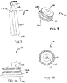
- FIG. 3 shows a side profile view of the heat sink 100 of FIG. 1 .
- the interface feature 102 shows here has two substantially flat surfaces of unequal sizes, a larger surface 102a and a smaller surface 102b, each adapted for providing a mounting surface and a good thermal interface with a heat generating source, if desired.
- the interface feature 102 is of a smaller diameter as the diameter of the closed end of the housing 101, resulting in shoulder-like portion 1000 protruding from beneath the interface feature 102.
- FIG. 4 shows a perspective view of the exterior of a capping device 103, adapted for fitting into a heat sink, as shown in FIGs. 1, 2 , 6 and 7 .
- the end portion 105 is adapted to be inserted into the hollow interior 107 of a heat sink, such as shown in FIG. 1 , and the second end portion 104 is exposed on the outside of the heat sink 100.
- a circumferential groove 106a may be included in the vertical wall section 106. This groove is adapted to accommodate an o-ring, a gasket, or other sealing features to provide a air and/or moisture tight seal.
- FIG. 4a shows a side view of the capping device 103 exemplified in FIG. 4 .
- the capping device includes a channel or dent 110, adapted for positioning a thermistor or other thermal sensors.
- the dent 110 may be present in a raised portion or mound 120 of the capping device 103.
- the mound 120 is of a smaller diameter as the rest of the capping device.
- the capping device 103 may be held in place inside the open end 101b of the housing by a number of ways. In the example as shown in FIG. 5 , it is held in place by at least one formation 111, adapted for compression fitting the larger circumference of the end portion 105 of the capping device 103 against the inside wall of the housing 101.
- a circumferential groove 106a is shown here as having a substantial vertical portion having a reduced diameter. The groove 106a may be molded or machined into the capping device. As noted, this groove is adapted to fit an o-ring, a gasket or other sealing features for sealing the open end of the housing.
- the bottom or exposed end 104 of the capping device 103 has a substantially equal diameter or dimension as the outside diameter or dimension as the open end of the housing 101, so that the capping device may be flush with the outside vertical wall of the housing 101.
- the diameter of the bottom end 104 of the capping device 103 may be of a larger diameter or dimension as the open end of the housing 101, so that the capping device protrudes from the side of the heat sink to facilitate removal of the capping device 103, if desired.
- FIG. 4b shows a top view of the capping device 103 of FIG. 4 . As exemplified in this view, the larger diameter of the bottom end 104 than that of the vertical wall section 106 is clearly shown.
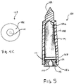
- FIG. 4c shows the bottom view of the capping device 103 of FIG. 4 , where the depression 110, adapted for holding a thermistor or other thermal sensors, is clearly shown.
- the depression as shown has a circular cross-section, but nay other shape may be suitable.
- FIG. 5 shows a cross-sectional view of a heat sink 100 of the present invention.
- the hollow interior 107 includes an open end 101b, which is shown to be capped with a capping device 103, and a closed end 101a.
- the hollow interior 107 is shown to be substantially filled with a solid phase change material 108, which may include any of the materials described before.
- the capping device 103 is shown in place, sealing the hollow interior 107 by means of an o-ring 109.
- the capping device 103 may be held in place by at least one formation 111, adapted for compression fitting the circumference 106 (as shown in FIG. 4a ) of the capping device against the inside wall of the housing 101.
- the cap may also include a channel 110, adapted, for example, to house a thermistor or other thermal sensors.
- the thermistor or other thermal sensors may be fixed to the channel with a thermally conductive adhesive, such as a structural or permanent adhesive, or a reactive adhesive, for example, an epoxy, a silicone adhesive, a contact cement, or a cyanoacrylate based adhesive, an acrylic-based, a polyurethane-based, a polyamide-based, a styrene copolymer-based, a polyolefin-based or similar, to allow the sensor to provide temperature information to a curing light control system to keep the curing light from becoming too hot to handle or to be over-heated.
- a thermally conductive adhesive such as a structural or permanent adhesive, or a reactive adhesive, for example, an epoxy, a silicone adhesive, a contact cement, or a cyanoacrylate based adhesive, an acrylic-based, a polyurethane-based, a polyamide-based
- the capping device 103 may also be sealed to an open end of the housing using a structural adhesive, such as those mentioned above in connection with the thermistor.
- the adhesive seals any pin holes that may exist.
- pin holes or vent holes may be desirable to allow gas to escape.
- a vapor impermeable/moisture permeable layer or film may be used to cover the holes.
- the heat sink includes a well and an LED or laser diode chip or chips may be mounted in the well. Light emitted from the side(s) of the LED or laser diode chip or chips may be reflected off the walls of the well to travel in a desired direction. In other embodiments, the well may be deep, as shown in FIG. 6 below.
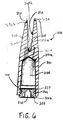
- FIG. 6 shows a cross-sectional view of another embodiment of a heat sink 300 of the current invention.
- the housing 301 includes a well 312 in place of a protruding feature, such as an interface feature, as shown above.
- the exemplified embodiment shows an elongated or substantially cylindrical heat sink 300, except that it has a curved structure, for example, a well or depression 312.
- the well 312 may be deep, having side walls 320 with the proximal portion 312b being at the top of the well and the distal portion 312a at the bottom of the well, adapted for positioning at least a light source such as an LED or LED array 313 at either its distal end 312a or the proximal portion 312b of the well or depression 312, to diffuse the concentration of heat generation.
- a light source such as an LED or LED array 313
- the proximal portion of the well 312 may include at least two mounting platforms 313a, located, for example, approximately opposite each other, and at least one mounting platform 313a located towards the distal portion 312a of the elongated heat sink, for mounting at least one light source 313.
- These mounting platforms may be surfaces on the heat sink housing, as discussed before.
- the heat sink 300 may also include at least one channel or valley, which may or may not run the length of the housing 301, as discussed above.
- a channel or valley (not shown) may also be present along the inner side wall 302b for wiring components.
- the light sources 313 may be capable of emitting the same or different wavelengths.
- This heat sink construction may be capable of more effective heat dissipation by not concentrating the heat product at one location.
- each of the light sources 313 may include a light emitting diode (LED), or an LED array. Each of the LEDs (or LED arrays) emits light useful for initiating curing of a light activated material. In one embodiment, the combined light sources 313 may emit light of multiple wavelengths for activating a photoinitiator or multiple photoinitiators.
- LED light emitting diode
- each of the LEDs or LED arrays
- the combined light sources 313 may emit light of multiple wavelengths for activating a photoinitiator or multiple photoinitiators.
- the well 312 may accommodate the placement of LEDs 313 within the well and/or at the proximal portion 312b. Heat from the LEDs 313 may be conducted away by the housing 301.
- the side wall of the well may be of a solid thermal conductive or metallic material. The material may be the same thermal conductive or metallic material as the rest of the housing 301, without a hollow interior.
- the side wall includes an inner side wall 320a and an outer side wall 320b surrounding a partially hollow interior of the well 312. This space may be filled with some phase change material as well, or may provide expansion space for the phase change material when it changes from one phase, occupying one space, into a phase occupying a larger space.
- a capping device 303 may also be used to seal the hollow interior 307 at the open end 301b with an o-ring 309 and a formation 311 for a compression fit.
- a thermistor or other thermal sensor may be disposed in the channel 310 and fixed with a thermally conductive adhesive, such as those mentioned above, again to allow temperature information to be passed to a curing light control system.
- the capping device 303 may also be sealed with an adhesive to seal any pin holes that may exist. In other embodiments, pin holes or vent holes may be desirable to allow gas to escape. Again, to minimize any liquid phase change material from escaping, a vapor impermeable/moisture permeable layer or film may be used to cover the holes.
- FIG. 7 shows another embodiment of a heat sink of the present invention.
- the heat sink 400 is of a square cross-section, having a housing 401, and a substantially hollow interior 402.
- the heat sink may be an elongated heat sink as shown, and the interior may either be of a substantially rectangular shape or a cylindrical shape.
- This heat sink may be fitted again with a capping device 403, with a depression at the top of the capping device.
- An elastomeric gasket 409 may be again disposed about a channel 409a in the capping device.
- the interior of the housing may also include a divider in one embodiment and no divider in another.
- This heat sink may also be filled with a phase change material, as discussed above.
- the gasket or o-ring may be made of any elastomeric or rubber material for providing a seal to minimize exposure of the phase change material to the environment outside of the housing.
- the housing may also have vent holes to allow the escape of gases, as mentioned above. In such embodiments, the recyclability of the heat sink may be reduced unless completely recyclable phase change materials are used.
- these vent holes may also be covered with a vapor permeable, moisture impermeable layer, as mentioned above, surrounding the phase change material on the inside of the housing.
- the vapor permeable, moisture impermeable layer may surround at least the portion of the housing having the vent holes on the outside of the housing.
- vapor permeable and moisture impermeable materials may include a water vapor permeable polyurethane film formed from a hot melt moisture curing adhesive containing at least one isocyanate functional polyurethane (which may be a reaction product of a component that contains NCO groups and a diol component with at least one linear dihydroxy polyester, formed from a diacid constituent and a diol constituent, the diol constituent may be a dihydroxy poplyether having a weight average molecular weight of at least 1000, and the ratio of OH:NCO in the isocyanate functional polyurethane is between 1.0:1.6 and 1.0:2.6) (disclosed in U.S. patent No.
- a film layer formed from a composition of a non-curing thermoplastic composition containing ethylene methacrylic acid copolymer or a polyether block amide, and at least one diluent such as a plasticizer (disclosed in U.S. Patent No.
- thermoplastic composition made with a non-contact coating method to produce a substantially continuous coating of a variety of adhesives (such as polyethylene, polypropylene, copolymers of olefins, especially ethylene, and (meth-) acrylic acid; copolymers of olefins, such as ethylene, and (meth-) acrylic acid derivatives of (meth-) acrylic acid esters; copolymers of olefins, such as ethylene, and vinylic compounds of vinyl carboxylates such as vinyl acetate; thermoplastic rubbers (or synthetic rubbers) such as styrene-isoprene-styrene, styrene-butadiene-styrene, styrene-ethylene/butylene-styrene and styrene-ethylene/propylene-styrene block copolymers available in commerce under the tradenames of Kraton®, Solpren
- Any embodiment of the heat sink described above may be constructed as a module so that it may be changed or exchanged when needed.
- the embodiments of heat sink described above may be used in a curing light system.
- the curing light may be a hand-held portable curing light system operated by batteries or a chair side curing light system operated by AC power.
- a heat sink including a phase change material may be installed in the curing light or a photobleaching light device in the same manner a conventional metal block heat sink is installed.
- some curing lights and photobleaching lights are generally supported when in use, therefore the weight of the device is not as problematic.
- a more efficient heat sink may be beneficial and can nevertheless lead to the construction of a more compact bleaching light.
- the heat sink including at least one phase change material may be used by itself or in conjunction with a conventional metal heat sink or a fan.
- an additional cooling system such as a liquid coolant may also be used.
- FIG. 8 shows an embodiment of a curing light 1000 of the present invention, having a light module housing 1010 including a distal end 1110, a proximal end 1120, a handle 1020 towards its distal end and a neck and head portion 1030 on its proximal end at an angle to the handle portion 1020.
- the light module housing 1010 has a substantially cylindrical shape having a substantially hollow interior 1010a with at least one heat sink 1200 located in the light module housing 1010.
- the heat sink 1200 may have a longitudinal axis, or may be of any configuration adapted to promote effective thermal management within the curing light 1000.
- the head and neck portion 1030 may also include a light guide, such as the internal light guide 1700 shown here in FIG. 8 .
- the curing light may include an external light guide.
- a lens cover 1650 may be located towards the proximal end of the light module housing 1010, as shown.
- the lens cover 1650 may be a transparent window through which light travels before striking a composite material to be cured or whitening material to be acted on.
- the housings include sealed plastic and sealed metal ends with a window.
- the cover 1650 may be a focusing device, which may include a focusing lens or dome 1740 for focusing the light towards a target surface.
- the housing 1010 may have a focusing dome 1740 integrally bonded to or formed or molded with the housing, to focus light emitted by the laser diodes or the light emitting diodes before delivering it to a remote location.
- the housing may be constructed therefore not only to serve to protect the light source, but also serve to focus light.
- the focusing dome or lens 1740 may also act as a device for modifying the footprint or varying the diameter of the light beam exiting the proximal end 1120 of the housing 1010, in order to more correctly direct the beam of light, either at a smaller target area or over a wider target area.
- the light module housing 1010 also houses and protects, for example, electronic circuits 1420 and a DC battery pack 1440.
- one embodiment includes an elongated heat sink 1200 having a distal end 1200a and a proximal end 1200b.
- the heat sink 1200 may be located in the light module housing 1010 with the proximal end 1200b being situated closer to the proximal end 1120 of the housing 1010.
- the heat sink 1200 may also be in any other shape.
- At least one mounting platform (not shown) or simply a surface may be located at the distal end 1200a, and at the proximal end 1200b of the elongated heat sink 1200. When other shapes of the heat sink are included in the invention, the mounting platforms may be located at the proximal or distal surface or portion.
- a light source 1300 Mounted on each of the mounting platforms or surfaces is a light source 1300.
- the light source is, for example, an LED or an LED array.
- the light sources may be located towards the proximal end of the housing 1010, so that they are close to the target area.
- the device is fitted with a light guide 1700 to keep one or more of the light sources away from the target.
- the light guide 1700 here may be an extension of the housing 1010.
- the chips of the light source when used, may be collectively located on a single heat sink for heat dissipation or individually seated to its own heat sink. In some embodiments, the light source may be seated on a larger heat sink with electrode channels.
- the heat sink including phase change material of the present invention may be in direct or indirect contact with the light emitting chip or chips. After the phase change material absorbs the heat generated by the chips, heat may then be dissipated.
- a conventional metal heat sink may be mounted adjacent to the heat sink of the present invention including at least one phase change material, either beside or beneath it.
- a fan may also be provided in lieu of or in addition to the conventional metal heat sink.
- single or multiple LED chips or laser diode chips may be located on a conventional metal block heat sink, which directly absorbs heat generated by the light source or sources, and the heat sink including at least one of the phase change material absorbs the heat coming from the thermally conductive or metal block.
- the heat sink including at least one phase change material may dissipate heat coming from the thermally conductive or metal block by being mounted adjacent to, either beside, or beneath the conventional metal block heat sink.
- the chips of the light source are either collectively located on a single heat sink including phase change material for heat dissipation or individually seated to its own heat sink including phase change material.
- a light source including LED's or laser diode chips may be located on a face of the heat sink and around the periphery of that face of the heat sink. In this configuration, more LED's or laser diode chips be placed on the heat sink either to achieve a more powerful light or to accommodate the necessary number of wavelengths of light that are desired to be produced.
- electrodes providing power to the laser or the LED chips may also be included in the housing.
- the phase change material may be, for example, in a solid state at ambient temperature, although a liquid may also be used if special provisions are made for containing the gas produced during phase change.
- heat is generated by the light source or sources, it is conducted away by the thermally conductive or metal casing or metal wall and absorbed by the phase change material.
- the solid or liquid absorbs heat from the casing and undergoes a phase change to a liquid or gas, respectively. Some sublimation may also be happening.
- an internal thermal sensor may be provided to effect the shut off of the curing light or bleaching light at a given temperature.
- the liquefied or gasified phase change material then begins to dissipate heat, when the thermally conductive or metal casing is removed from any heat generating source, for example, the light source is turned off. This heat dissipation is again through the thermally conductive or metal casing, in an attempt by the phase change material to return to its initial state of solid or liquid, respectively.
- the phase change material comes substantially close to ambient temperature, it will then remain a solid or liquid until it once again experiences a rise in temperature to its melting or gasifying point and the process is repeated. Since the phase change material undergoes substantially reversible phase changes, it may typically go through a large, if not an infinite number of cycles without losing its effectiveness.
- the light from the light source exits the housing and travels directly to a curing surface without first going through a light guide or fiber optic cable. In other embodiments, the light travels from the light source to a curing surface by first going through a light guide or fiber optic cable.
- the light source may be, for example, located in a handle that may be manipulated by a user in order to direct light emitted by the light source to composite materials to be cured.
- at least a portion of handle is flexible and may be bent in any desired direction for ease of use.
- the flexible portion includes at least a soft protective material surrounding at least one bendable wire.
- the heat coming out of the housing may be dissipated by a heat sink including the phase change material, a conventional metal block, or a fan, located in the handle, or just by ambient air.
- diode lasers or light emitting diodes may be arranged in an array on an appropriate base or fixture in order to provide greater light power or to provide a varying diameter light source if a concentric array is used. Further, when an array of laser or light emitting diode chips is used, a light with single or multiple wavelengths may be achieved by placing the chips with different wavelength in the array.
- the curing or photobleaching light system may be equipped with a control module with AC or DC power.
- the control module powers and controls the curing or photobleaching light system so that appropriate light for curing a composite material or for bleaching a photoactive bleaching composition is provided at a desired light intensity for any desired time duration.
- An on/off switch and an indicator for low battery power can also be provided.
- a battery charger is provided for charging one or more batteries used to power the light source.
- the curing or photobleaching light may still be used for treatment because power can be drawn from the charger to power the curing light.
- phase change material Phase change material (PCM): Sodium Hydrogen Phosphate Dodecahydrate (Na 2 HPO 4 ⁇ 12 H 2 O) having the following properties:
- phase change material was heated for 45 minutes at 55°C in an oven until melted.
- 1.2 mL of phase change material in liquid phase was loaded into the hollow copper casing of the heat sink using a syringe.
- the heat sink was cooled with a fan for 30 minutes before a cap was pressed into place to seal the chamber.
- a thermistor was placed into the channel of the cap and sealed into place with thermal epoxy. Additional thermal epoxy was also applied to the interior of the cap to provide further sealing.
- the constructed heat sink of the above specified configuration was tested in a curing light in accordance with the present invention.
- the testing consisted of determining the run-time of the curing light when utilizing a heat sink including a phase change material in comparison to a heat sink without a phase change material.
- Run-time testing determined the operational time prior to the curing light shut-off temperature. A rise of temperature to 40°C from an ambient temperature of 25°C was obtained.
- the curing light employing a heat sink including a phase change material averaged a run-time of greater than 20 minutes (a total of 20 samples with approximately the same construction was run) and the curing light employing a comparable heat sink except without a phase change material averaged a run-time of about 8 minutes (a total of 67 samples were run).
- the heat sink of the present invention demonstrated a superior performance when compared to conventional solid metal block heat sinks, even at a lower weight.
Applications Claiming Priority (12)
| Application Number | Priority Date | Filing Date | Title |
|---|---|---|---|
| US58522404P | 2004-07-02 | 2004-07-02 | |
| US60457704P | 2004-08-25 | 2004-08-25 | |
| US63126704P | 2004-11-26 | 2004-11-26 | |
| US64146905P | 2005-01-04 | 2005-01-04 | |
| US64146805P | 2005-01-04 | 2005-01-04 | |
| US64758005P | 2005-01-26 | 2005-01-26 | |
| US64761205P | 2005-01-26 | 2005-01-26 | |
| US65851705P | 2005-03-03 | 2005-03-03 | |
| US66469605P | 2005-03-22 | 2005-03-22 | |
| US59429705P | 2005-03-25 | 2005-03-25 | |
| US59432705P | 2005-03-30 | 2005-03-30 | |
| PCT/US2005/023736 WO2006014402A2 (en) | 2004-07-02 | 2005-06-30 | Dental light device having an improved heat sink |
Publications (3)
| Publication Number | Publication Date |
|---|---|
| EP1776058A2 EP1776058A2 (en) | 2007-04-25 |
| EP1776058A4 EP1776058A4 (en) | 2012-03-14 |
| EP1776058B1 true EP1776058B1 (en) | 2018-12-26 |
Family
ID=35599211
Family Applications (1)
| Application Number | Title | Priority Date | Filing Date |
|---|---|---|---|
| EP05769322.8A Active EP1776058B1 (en) | 2004-07-02 | 2005-06-30 | Dental light device having an improved heat sink |
Country Status (8)
| Country | Link |
|---|---|
| US (2) | US20090233254A1 (zh) |
| EP (1) | EP1776058B1 (zh) |
| JP (1) | JP5280051B2 (zh) |
| CN (1) | CN100569194C (zh) |
| AU (1) | AU2005270047B2 (zh) |
| CA (1) | CA2572548C (zh) |
| MX (1) | MXPA06014977A (zh) |
| WO (1) | WO2006014402A2 (zh) |
Families Citing this family (37)
| Publication number | Priority date | Publication date | Assignee | Title |
|---|---|---|---|---|
| US7212615B2 (en) * | 2002-05-31 | 2007-05-01 | Scott Wolmuth | Criteria based marketing for telephone directory assistance |
| US20050053895A1 (en) | 2003-09-09 | 2005-03-10 | The Procter & Gamble Company Attention: Chief Patent Counsel | Illuminated electric toothbrushes emitting high luminous intensity toothbrush |
| CN101014295A (zh) * | 2004-07-02 | 2007-08-08 | 底斯柯斯牙齿印模公司 | 具有反射器的固化光装置 |
| US7322732B2 (en) * | 2004-12-23 | 2008-01-29 | Cree, Inc. | Light emitting diode arrays for direct backlighting of liquid crystal displays |
| US20060261359A1 (en) * | 2005-05-18 | 2006-11-23 | Hsien-Jung Huang | Heat sink for light emitting diode bulb |
| DE102005019386B4 (de) * | 2005-04-26 | 2010-07-29 | Ivoclar Vivadent Ag | Gerät zum Polymerisieren von polymerisierbarem Dentalmaterial sowie Verfahren zur Bestimmung des Polymerisationsgrades |
| US8459852B2 (en) | 2007-10-05 | 2013-06-11 | Dental Equipment, Llc | LED-based dental exam lamp |
| DE102007002796A1 (de) * | 2007-01-18 | 2008-07-24 | Alzchem Trostberg Gmbh | Verwendung von Amid-Verbindungen zur Speicherung von latenter Wärme |
| DE102007013783A1 (de) * | 2007-03-22 | 2008-10-02 | Ivoclar Vivadent Ag | Lichthärtgerät-Basisstation-Kombination |
| US7810965B2 (en) | 2008-03-02 | 2010-10-12 | Lumenetix, Inc. | Heat removal system and method for light emitting diode lighting apparatus |
| US9102857B2 (en) * | 2008-03-02 | 2015-08-11 | Lumenetix, Inc. | Methods of selecting one or more phase change materials to match a working temperature of a light-emitting diode to be cooled |
| US9228732B2 (en) | 2008-07-08 | 2016-01-05 | Us Vaopto, Inc. | Modular LED lighting systems, including flexible, rigid, and waterproof lighting strips and connectors |
| US8631855B2 (en) * | 2008-08-15 | 2014-01-21 | Lighting Science Group Corporation | System for dissipating heat energy |
| CA2676315A1 (en) | 2008-08-22 | 2010-02-22 | Virginia Optoelectronics, Inc. | Led lamp assembly |
| EP2196167A1 (en) * | 2008-12-10 | 2010-06-16 | 3M Innovative Properties Company | Dental light device |
| KR101654664B1 (ko) | 2008-12-30 | 2016-09-06 | 울트라덴트 프로덕츠, 인코포레이티드 | 방열기로서 작용하는 단일체 설계를 갖는 치과용 경화 광 |
| WO2011094293A1 (en) * | 2010-01-27 | 2011-08-04 | Fusion Uv Systems, Inc. | Micro-channel-cooled high heat load light emitting device |
| US8123389B2 (en) | 2010-02-12 | 2012-02-28 | Lumenetix, Inc. | LED lamp assembly with thermal management system |
| US20110214124A1 (en) * | 2010-02-26 | 2011-09-01 | James Michael Ferris | Systems and methods for generating cross-cloud computing appliances |
| JP2013526349A (ja) * | 2010-05-12 | 2013-06-24 | ディスカス デンタル,エルエルシー | 識別手段を持つ歯科用ライト装置 |
| US9642687B2 (en) | 2010-06-15 | 2017-05-09 | The Procter & Gamble Company | Methods for whitening teeth |
| US9144480B2 (en) * | 2011-03-11 | 2015-09-29 | Schott Corporation | Light-emitting wand with electrically-conductive heat sinks |
| GB201105833D0 (en) * | 2011-04-06 | 2011-05-18 | Optilume Ltd | Light curing device and method of use thereof |
| CN102359111B (zh) * | 2011-10-26 | 2014-04-16 | 中冶集团武汉勘察研究院有限公司 | 水下砼浇筑标高控制装置及使用方法 |
| JP6023472B2 (ja) * | 2012-06-06 | 2016-11-09 | オリンパス株式会社 | 光源装置 |
| DE102012212429A1 (de) | 2012-07-16 | 2014-01-16 | Voco Gmbh | Dentalhandgerät, Verfahren und Verwendung desselben zum Aushärten lichthärtbaren Materials |
| KR101338556B1 (ko) * | 2012-08-09 | 2013-12-06 | 현대모비스 주식회사 | 차량용 헤드램프의 습기발생 방지 구조 |
| US9168662B1 (en) * | 2012-12-03 | 2015-10-27 | Kevin Brown | Lighted razor |
| US10736433B2 (en) * | 2013-07-29 | 2020-08-11 | Fine Cotton Factory Inc. | Fire resistant fabric |
| EP3193776B1 (en) | 2014-09-17 | 2022-01-05 | Garrison Dental Solutions LLC | Dental curing light |
| US9662191B2 (en) * | 2015-07-08 | 2017-05-30 | Monitex Industrial Co., Ltd. | Dental light curing device |
| EP3263177B1 (en) * | 2016-06-27 | 2019-06-26 | Braun GmbH | Skin treatment device |
| USD842469S1 (en) | 2016-11-19 | 2019-03-05 | Azena Medical, LLC | Laser system |
| CN110267622B (zh) * | 2016-12-15 | 2021-08-13 | 洁碧有限公司 | 带有照亮特征的刷洗设备 |
| USD810293S1 (en) | 2017-01-20 | 2018-02-13 | Garrison Dental Solutions, Llc | Dental instrument |
| CN106931382B (zh) * | 2017-03-29 | 2023-03-21 | 华南理工大学 | 一种用于led车灯的散热元件及其制备方法 |
| CN111557731B (zh) * | 2020-05-25 | 2022-12-20 | 无锡欧莱美激光科技有限公司 | 手持式家用激光美容仪 |
Family Cites Families (92)
| Publication number | Priority date | Publication date | Assignee | Title |
|---|---|---|---|---|
| US4825939A (en) * | 1984-08-31 | 1989-05-02 | The University Of Dayton | Polymeric compositions incorporating polyethylene glycol as a phase change material |
| US4615679A (en) * | 1985-06-03 | 1986-10-07 | Wyatt Thomas K | Light shield for use with light curing apparatus |
| US4632865A (en) * | 1985-11-13 | 1986-12-30 | Mediavault Inc. | Multi-layer intumescent-ablator endothermic fire retardant compositions |
| JPH06101294B2 (ja) * | 1986-02-10 | 1994-12-12 | 松下電工株式会社 | 引外しコイルの固定装置 |
| US4955361A (en) * | 1986-10-31 | 1990-09-11 | The Furukawa Electric Co., Ltd. | Hot plate |
| JPH03102856A (ja) * | 1989-09-14 | 1991-04-30 | Fujitsu Ltd | 電子装置の冷却装置 |
| DE4143454C2 (de) | 1991-07-01 | 1995-01-05 | Fuller H B Licensing Financ | Verfahren zur Herstellung eines wasserdampfdurchlässigen Materials sowie ein solches Material |
| JP2847682B2 (ja) * | 1991-11-22 | 1999-01-20 | 松下電器産業株式会社 | 交通信号無視取締り装置 |
| US5629840A (en) * | 1992-05-15 | 1997-05-13 | Digital Equipment Corporation | High powered die with bus bars |
| US6004662A (en) * | 1992-07-14 | 1999-12-21 | Buckley; Theresa M. | Flexible composite material with phase change thermal storage |
| DE4240081C1 (de) * | 1992-11-28 | 1994-04-28 | Erno Raumfahrttechnik Gmbh | Wärmerohr |
| US5420768A (en) * | 1993-09-13 | 1995-05-30 | Kennedy; John | Portable led photocuring device |
| US6207738B1 (en) * | 1994-06-14 | 2001-03-27 | Outlast Technologies, Inc. | Fabric coating composition containing energy absorbing phase change material |
| US5719559A (en) * | 1995-06-23 | 1998-02-17 | Limitorque Corporation | System and method for the verification of a digital control system |
| US6264854B1 (en) * | 1995-09-07 | 2001-07-24 | Claude Q. C. Hayes | Heat absorbing temperature control devices and method |
| JP2845221B2 (ja) * | 1996-10-25 | 1999-01-13 | 日本電気株式会社 | 潜熱利用型ヒートシンク |
| DE29709228U1 (de) * | 1997-05-26 | 1998-09-24 | Thera Ges Fuer Patente | Lichtpolymerisationsgerät |
| US6780505B1 (en) * | 1997-09-02 | 2004-08-24 | Ut-Battelle, Llc | Pitch-based carbon foam heat sink with phase change material |
| BR9813223A (pt) | 1997-09-25 | 2000-08-29 | Univ Bristol | Dispositivo de radiação ótica |
| AUPO954697A0 (en) * | 1997-09-30 | 1997-10-23 | Powder Design Pty. Ltd. | Snowboard safety release binding |
| US6287305B1 (en) * | 1997-12-23 | 2001-09-11 | Team Medical, L.L.C. | Electrosurgical instrument |
| DE19753266B4 (de) | 1997-12-01 | 2010-10-07 | H.B. Fuller Licensing & Financing, Inc., St. Paul | Verfahren zum Verbinden luftundurchlässiger Materialien |
| US6200134B1 (en) * | 1998-01-20 | 2001-03-13 | Kerr Corporation | Apparatus and method for curing materials with radiation |
| US6077073A (en) * | 1998-09-15 | 2000-06-20 | Jacob; Gregory S. | Light emitting diode-array light apparatus |
| US6514075B1 (en) * | 1998-09-15 | 2003-02-04 | Gregory S. Jacob | Dental curing apparatus for light-sensitive materials |
| US6274924B1 (en) | 1998-11-05 | 2001-08-14 | Lumileds Lighting, U.S. Llc | Surface mountable LED package |
| US6432547B1 (en) | 1999-02-22 | 2002-08-13 | H.B. Fuller Licensing & Financing Inc. | Breathable film layer compositions |
| US6848500B1 (en) * | 1999-03-11 | 2005-02-01 | Skyworks Solutions, Inc. | Cooling system for pulsed power electronics |
| US6439888B1 (en) * | 1999-05-03 | 2002-08-27 | Pls Liquidating Llc | Optical source and method |
| US6759476B1 (en) * | 1999-07-14 | 2004-07-06 | Claude Q. C. Hayes | Flexible thermal control composite |
| US6981867B2 (en) * | 1999-09-24 | 2006-01-03 | Cao Group, Inc. | Curing light |
| US6755649B2 (en) * | 1999-09-24 | 2004-06-29 | Cao Group, Inc. | Curing light |
| US7086858B2 (en) * | 1999-09-24 | 2006-08-08 | Cao Group, Inc. | Semiconductor curing light system useful for curing light activated composite materials |
| US6719559B2 (en) * | 1999-09-24 | 2004-04-13 | Densen Cao | Curing light |
| US6929472B2 (en) * | 1999-09-24 | 2005-08-16 | Cao Group, Inc. | Curing light |
| US6755648B2 (en) * | 1999-09-24 | 2004-06-29 | Cao Group, Inc. | Curing light |
| US6979193B2 (en) * | 1999-09-24 | 2005-12-27 | Cao Group, Inc. | Curing light |
| US6971876B2 (en) * | 1999-09-24 | 2005-12-06 | Cao Group, Inc. | Curing light |
| US6988891B2 (en) * | 1999-09-24 | 2006-01-24 | Cao Group, Inc. | Curing light |
| US6926524B2 (en) * | 1999-09-24 | 2005-08-09 | Cao Group, Inc. | Curing light |
| US6969253B2 (en) * | 1999-09-24 | 2005-11-29 | Cao Group, Inc. | Light for use in activating light-activated materials, the light having at least one light emitting semiconductor chip, the chip being attached to a primary heat sink that is attached to a secondary heat sink using heat conductive and electrically insulative adhesive |
| US6971875B2 (en) * | 1999-09-24 | 2005-12-06 | Cao Group, Inc. | Dental curing light |
| US7066732B2 (en) * | 1999-09-24 | 2006-06-27 | Cao Group, Inc. | Method for curing light-curable materials |
| US6719558B2 (en) * | 1999-09-24 | 2004-04-13 | Densen Cao | Curing light |
| US6331111B1 (en) * | 1999-09-24 | 2001-12-18 | Cao Group, Inc. | Curing light system useful for curing light activated composite materials |
| US6780010B2 (en) * | 1999-09-24 | 2004-08-24 | Cao Group, Inc. | Curing light |
| US6910886B2 (en) * | 1999-09-24 | 2005-06-28 | Cao Group, Inc. | Curing light |
| US6988890B2 (en) * | 1999-09-24 | 2006-01-24 | Cao Group, Inc. | Curing light |
| US6783362B2 (en) * | 1999-09-24 | 2004-08-31 | Cao Group, Inc. | Dental curing light using primary and secondary heat sink combination |
| US7294364B2 (en) * | 1999-09-24 | 2007-11-13 | Cao Group, Inc. | Method for curing composite materials |
| US6824294B2 (en) * | 1999-09-24 | 2004-11-30 | Cao Group, Inc. | Light for use in activating light-activated materials, the light having a plurality of chips mounted in a gross well of a heat sink, and a dome covering the chips |
| US7077648B2 (en) * | 1999-09-24 | 2006-07-18 | Cao Group, Inc. | Curing light |
| US6932600B2 (en) * | 1999-09-24 | 2005-08-23 | Cao Group, Inc. | Curing light |
| US6318996B1 (en) * | 1999-10-05 | 2001-11-20 | Noureddine Melikechi | Method for curing a dental composition using a light emitting diode |
| ATE275885T1 (de) * | 1999-11-29 | 2004-10-15 | Mectron S R L | Zahnärztliches handstück zur fotopolymerisation kompatibel zu der energieversorgungseinrichtung von anderen handstücken |
| US6354370B1 (en) * | 1999-12-16 | 2002-03-12 | The United States Of America As Represented By The Secretary Of The Air Force | Liquid spray phase-change cooling of laser devices |
| DE10006286C1 (de) * | 2000-02-14 | 2001-10-18 | 3M Espe Ag | Lichtwellenkonvertervorrichtung und deren Verwendung im Dentalbereich |
| US6419483B1 (en) * | 2000-03-01 | 2002-07-16 | 3M Innovative Properties Company | Method and apparatus for curling light-curable dental materials |
| US7320593B2 (en) * | 2000-03-08 | 2008-01-22 | Tir Systems Ltd. | Light emitting diode light source for curing dental composites |
| US20030036037A1 (en) * | 2000-03-27 | 2003-02-20 | Zavitsanos Peter D. | System and method for whitening teeth |
| US6517218B2 (en) * | 2000-03-31 | 2003-02-11 | Relume Corporation | LED integrated heat sink |
| US6809740B1 (en) * | 2000-07-26 | 2004-10-26 | Lexmark International, Inc. | Dithered quantization using neighborhood mask array to approximate interpolate |
| US6616447B1 (en) * | 2000-11-15 | 2003-09-09 | Biolase Technology, Inc. | Device for dental care and whitening |
| US6695614B2 (en) * | 2001-02-01 | 2004-02-24 | Ivoclar Vivadent Ag | Light beam hardening apparatus for curing material |
| US6709128B2 (en) * | 2001-03-26 | 2004-03-23 | Ocumed, Inc. | Curing system |
| US6468077B1 (en) * | 2001-04-26 | 2002-10-22 | New Photonics, Llc | Compact device for curing dental compositions and method of curing |
| JP2003032525A (ja) * | 2001-05-09 | 2003-01-31 | Seiko Precision Inc | 固体撮像装置 |
| CA2763127A1 (en) * | 2001-05-23 | 2002-11-28 | Palomar Medical Technologies, Inc. | Cooling system for a photocosmetic device |
| JP4409118B2 (ja) * | 2001-05-28 | 2010-02-03 | 電気化学工業株式会社 | 放熱部材形成用粒状材料及びその用途 |
| US7108504B2 (en) * | 2001-07-10 | 2006-09-19 | Cao Group, Inc. | Light for use in activating light-activated materials, the light having insulators and an air jacket |
| US6799967B2 (en) * | 2001-07-10 | 2004-10-05 | Cao Group, Inc. | Light for use in activating light-activated materials, the light having a plurality of light emitting single chip arrays |
| US20030036031A1 (en) * | 2001-08-20 | 2003-02-20 | Lieb Joseph Alexander | Light-emitting handpiece for curing photopolymerizable resins |
| JP4749631B2 (ja) * | 2001-09-20 | 2011-08-17 | 電気化学工業株式会社 | 放熱部材 |
| JP2003102853A (ja) * | 2001-09-28 | 2003-04-08 | Ya Man Ltd | レーザ光照射装置 |
| US6498355B1 (en) * | 2001-10-09 | 2002-12-24 | Lumileds Lighting, U.S., Llc | High flux LED array |
| US6835064B2 (en) * | 2001-11-09 | 2004-12-28 | Ivoclar Vivadent Ag | Light hardening device and method for hardening a polymerizable mass for dental applications |
| US6692252B2 (en) * | 2001-12-17 | 2004-02-17 | Ultradent Products, Inc. | Heat sink with geometric arrangement of LED surfaces |
| US6645598B2 (en) * | 2002-01-04 | 2003-11-11 | Robert J. Alderman | Cell insulation blanket with phase change material, and method of making |
| US20030215766A1 (en) * | 2002-01-11 | 2003-11-20 | Ultradent Products, Inc. | Light emitting systems and kits that include a light emitting device and one or more removable lenses |
| US6940659B2 (en) * | 2002-01-11 | 2005-09-06 | Ultradent Products, Inc. | Cone-shaped lens having increased forward light intensity and kits incorporating such lenses |
| US6703128B2 (en) * | 2002-02-15 | 2004-03-09 | Delphi Technologies, Inc. | Thermally-capacitive phase change encapsulant for electronic devices |
| US6702576B2 (en) * | 2002-02-22 | 2004-03-09 | Ultradent Products, Inc. | Light-curing device with detachably interconnecting light applicator |
| US6843967B2 (en) * | 2002-04-11 | 2005-01-18 | Pentron Laboratory Technologies, Llc | Curing unit |
| US7831990B2 (en) * | 2002-04-29 | 2010-11-09 | Sony Corporation | Generic adaptation layer for JVT video |
| EP2298229A1 (en) * | 2002-07-25 | 2011-03-23 | Jonathan S. Dahm | Method and apparatus for using light emitting diodes for curing |
| EP1555948A2 (en) * | 2002-10-23 | 2005-07-27 | Palomar Medical Technologies, Inc. | Phototreatment device for use with coolants and topical substances |
| JP2004152905A (ja) * | 2002-10-29 | 2004-05-27 | Kyocera Corp | 冷却素子およびそれを用いた発熱素子デバイス |
| US20040101802A1 (en) * | 2002-11-21 | 2004-05-27 | Scott Robert R. | Wide bandwidth led curing light |
| US6890175B2 (en) * | 2002-12-18 | 2005-05-10 | Ultradent Products, Inc. | Cooling system for hand-held curing light |
| US6991356B2 (en) * | 2002-12-20 | 2006-01-31 | Efraim Tsimerman | LED curing light |
| JP2005106496A (ja) * | 2003-09-29 | 2005-04-21 | Aisin Aw Co Ltd | ナビゲーション装置 |
| US7195482B2 (en) * | 2003-12-30 | 2007-03-27 | Ultradent Products, Inc. | Dental curing device having a heat sink for dissipating heat |
-
2005
- 2005-06-30 JP JP2007519525A patent/JP5280051B2/ja not_active Expired - Fee Related
- 2005-06-30 CA CA2572548A patent/CA2572548C/en not_active Expired - Fee Related
- 2005-06-30 AU AU2005270047A patent/AU2005270047B2/en not_active Ceased
- 2005-06-30 EP EP05769322.8A patent/EP1776058B1/en active Active
- 2005-06-30 US US11/631,222 patent/US20090233254A1/en not_active Abandoned
- 2005-06-30 US US11/173,274 patent/US7581846B2/en active Active
- 2005-06-30 CN CNB2005800217436A patent/CN100569194C/zh not_active Expired - Fee Related
- 2005-06-30 WO PCT/US2005/023736 patent/WO2006014402A2/en active Application Filing
- 2005-06-30 MX MXPA06014977A patent/MXPA06014977A/es active IP Right Grant
Non-Patent Citations (1)
| Title |
|---|
| None * |
Also Published As
| Publication number | Publication date |
|---|---|
| CN1976643A (zh) | 2007-06-06 |
| EP1776058A2 (en) | 2007-04-25 |
| US20090233254A1 (en) | 2009-09-17 |
| CA2572548C (en) | 2014-09-02 |
| WO2006014402A2 (en) | 2006-02-09 |
| EP1776058A4 (en) | 2012-03-14 |
| AU2005270047A1 (en) | 2006-02-09 |
| JP5280051B2 (ja) | 2013-09-04 |
| MXPA06014977A (es) | 2007-03-27 |
| US7581846B2 (en) | 2009-09-01 |
| AU2005270047B2 (en) | 2011-06-02 |
| CN100569194C (zh) | 2009-12-16 |
| US20060013014A1 (en) | 2006-01-19 |
| JP2008504907A (ja) | 2008-02-21 |
| CA2572548A1 (en) | 2006-02-09 |
| WO2006014402A3 (en) | 2006-12-28 |
Similar Documents
| Publication | Publication Date | Title |
|---|---|---|
| EP1776058B1 (en) | Dental light device having an improved heat sink | |
| US7195482B2 (en) | Dental curing device having a heat sink for dissipating heat | |
| US7273369B2 (en) | Curing light | |
| US6991356B2 (en) | LED curing light | |
| US6918762B2 (en) | Light-generating instrument | |
| US6709128B2 (en) | Curing system | |
| US7056116B2 (en) | Heat sink for dental curing light comprising a plurality of different materials | |
| US20060018123A1 (en) | Curing light having a reflector | |
| EP3780124B1 (en) | Dental curing light having unibody design that acts as a heat sink | |
| US20110236851A1 (en) | Dental light device | |
| US20080101073A1 (en) | Dental Light Devices Having an Improved Heat Sink | |
| US20120257390A1 (en) | Light curing device and method of use thereof | |
| KR20070051788A (ko) | 개선된 히트 싱크를 갖는 치과용 조명 장치 |
Legal Events
| Date | Code | Title | Description |
|---|---|---|---|
| PUAI | Public reference made under article 153(3) epc to a published international application that has entered the european phase |
Free format text: ORIGINAL CODE: 0009012 |
|
| 17P | Request for examination filed |
Effective date: 20061228 |
|
| AK | Designated contracting states |
Kind code of ref document: A2 Designated state(s): AT BE BG CH CY CZ DE DK EE ES FI FR GB GR HU IE IS IT LI LT LU MC NL PL PT RO SE SI SK TR |
|
| AX | Request for extension of the european patent |
Extension state: AL BA HR LV MK YU |
|
| DAX | Request for extension of the european patent (deleted) | ||
| RAP1 | Party data changed (applicant data changed or rights of an application transferred) |
Owner name: DISCUS DENTAL, LLC |
|
| A4 | Supplementary search report drawn up and despatched |
Effective date: 20120213 |
|
| RIC1 | Information provided on ipc code assigned before grant |
Ipc: A61C 1/00 20060101AFI20120207BHEP Ipc: A61B 1/06 20060101ALI20120207BHEP |
|
| 17Q | First examination report despatched |
Effective date: 20120709 |
|
| STAA | Information on the status of an ep patent application or granted ep patent |
Free format text: STATUS: EXAMINATION IS IN PROGRESS |
|
| REG | Reference to a national code |
Ref country code: DE Ref legal event code: R079 Ref document number: 602005055196 Country of ref document: DE Free format text: PREVIOUS MAIN CLASS: A61C0001000000 Ipc: A61C0013150000 |
|
| RIC1 | Information provided on ipc code assigned before grant |
Ipc: F28D 20/02 20060101ALI20180507BHEP Ipc: A61C 13/15 20060101AFI20180507BHEP Ipc: A61K 8/19 20060101ALI20180507BHEP Ipc: A61K 8/24 20060101ALI20180507BHEP Ipc: F28D 21/00 20060101ALI20180507BHEP Ipc: A61K 6/06 20060101ALI20180507BHEP Ipc: A61K 8/21 20060101ALI20180507BHEP Ipc: A61K 6/08 20060101ALI20180507BHEP Ipc: A61Q 11/00 20060101ALI20180507BHEP Ipc: A61K 8/20 20060101ALI20180507BHEP |
|
| GRAP | Despatch of communication of intention to grant a patent |
Free format text: ORIGINAL CODE: EPIDOSNIGR1 |
|
| STAA | Information on the status of an ep patent application or granted ep patent |
Free format text: STATUS: GRANT OF PATENT IS INTENDED |
|
| INTG | Intention to grant announced |
Effective date: 20180706 |
|
| GRAS | Grant fee paid |
Free format text: ORIGINAL CODE: EPIDOSNIGR3 |
|
| GRAA | (expected) grant |
Free format text: ORIGINAL CODE: 0009210 |
|
| STAA | Information on the status of an ep patent application or granted ep patent |
Free format text: STATUS: THE PATENT HAS BEEN GRANTED |
|
| AK | Designated contracting states |
Kind code of ref document: B1 Designated state(s): AT BE BG CH CY CZ DE DK EE ES FI FR GB GR HU IE IS IT LI LT LU MC NL PL PT RO SE SI SK TR |
|
| REG | Reference to a national code |
Ref country code: GB Ref legal event code: FG4D |
|
| REG | Reference to a national code |
Ref country code: CH Ref legal event code: EP |
|
| REG | Reference to a national code |
Ref country code: AT Ref legal event code: REF Ref document number: 1080366 Country of ref document: AT Kind code of ref document: T Effective date: 20190115 |
|
| REG | Reference to a national code |
Ref country code: DE Ref legal event code: R096 Ref document number: 602005055196 Country of ref document: DE |
|
| REG | Reference to a national code |
Ref country code: IE Ref legal event code: FG4D |
|
| PG25 | Lapsed in a contracting state [announced via postgrant information from national office to epo] |
Ref country code: LT Free format text: LAPSE BECAUSE OF FAILURE TO SUBMIT A TRANSLATION OF THE DESCRIPTION OR TO PAY THE FEE WITHIN THE PRESCRIBED TIME-LIMIT Effective date: 20181226 Ref country code: BG Free format text: LAPSE BECAUSE OF FAILURE TO SUBMIT A TRANSLATION OF THE DESCRIPTION OR TO PAY THE FEE WITHIN THE PRESCRIBED TIME-LIMIT Effective date: 20190326 Ref country code: FI Free format text: LAPSE BECAUSE OF FAILURE TO SUBMIT A TRANSLATION OF THE DESCRIPTION OR TO PAY THE FEE WITHIN THE PRESCRIBED TIME-LIMIT Effective date: 20181226 |
|
| REG | Reference to a national code |
Ref country code: NL Ref legal event code: MP Effective date: 20181226 |
|
| REG | Reference to a national code |
Ref country code: LT Ref legal event code: MG4D |
|
| PG25 | Lapsed in a contracting state [announced via postgrant information from national office to epo] |
Ref country code: SE Free format text: LAPSE BECAUSE OF FAILURE TO SUBMIT A TRANSLATION OF THE DESCRIPTION OR TO PAY THE FEE WITHIN THE PRESCRIBED TIME-LIMIT Effective date: 20181226 Ref country code: GR Free format text: LAPSE BECAUSE OF FAILURE TO SUBMIT A TRANSLATION OF THE DESCRIPTION OR TO PAY THE FEE WITHIN THE PRESCRIBED TIME-LIMIT Effective date: 20190327 |
|
| REG | Reference to a national code |
Ref country code: AT Ref legal event code: MK05 Ref document number: 1080366 Country of ref document: AT Kind code of ref document: T Effective date: 20181226 |
|
| PG25 | Lapsed in a contracting state [announced via postgrant information from national office to epo] |
Ref country code: NL Free format text: LAPSE BECAUSE OF FAILURE TO SUBMIT A TRANSLATION OF THE DESCRIPTION OR TO PAY THE FEE WITHIN THE PRESCRIBED TIME-LIMIT Effective date: 20181226 |
|
| PG25 | Lapsed in a contracting state [announced via postgrant information from national office to epo] |
Ref country code: PL Free format text: LAPSE BECAUSE OF FAILURE TO SUBMIT A TRANSLATION OF THE DESCRIPTION OR TO PAY THE FEE WITHIN THE PRESCRIBED TIME-LIMIT Effective date: 20181226 Ref country code: CZ Free format text: LAPSE BECAUSE OF FAILURE TO SUBMIT A TRANSLATION OF THE DESCRIPTION OR TO PAY THE FEE WITHIN THE PRESCRIBED TIME-LIMIT Effective date: 20181226 Ref country code: IT Free format text: LAPSE BECAUSE OF FAILURE TO SUBMIT A TRANSLATION OF THE DESCRIPTION OR TO PAY THE FEE WITHIN THE PRESCRIBED TIME-LIMIT Effective date: 20181226 Ref country code: ES Free format text: LAPSE BECAUSE OF FAILURE TO SUBMIT A TRANSLATION OF THE DESCRIPTION OR TO PAY THE FEE WITHIN THE PRESCRIBED TIME-LIMIT Effective date: 20181226 Ref country code: PT Free format text: LAPSE BECAUSE OF FAILURE TO SUBMIT A TRANSLATION OF THE DESCRIPTION OR TO PAY THE FEE WITHIN THE PRESCRIBED TIME-LIMIT Effective date: 20190426 |
|
| PG25 | Lapsed in a contracting state [announced via postgrant information from national office to epo] |
Ref country code: RO Free format text: LAPSE BECAUSE OF FAILURE TO SUBMIT A TRANSLATION OF THE DESCRIPTION OR TO PAY THE FEE WITHIN THE PRESCRIBED TIME-LIMIT Effective date: 20181226 Ref country code: IS Free format text: LAPSE BECAUSE OF FAILURE TO SUBMIT A TRANSLATION OF THE DESCRIPTION OR TO PAY THE FEE WITHIN THE PRESCRIBED TIME-LIMIT Effective date: 20190426 Ref country code: EE Free format text: LAPSE BECAUSE OF FAILURE TO SUBMIT A TRANSLATION OF THE DESCRIPTION OR TO PAY THE FEE WITHIN THE PRESCRIBED TIME-LIMIT Effective date: 20181226 Ref country code: SK Free format text: LAPSE BECAUSE OF FAILURE TO SUBMIT A TRANSLATION OF THE DESCRIPTION OR TO PAY THE FEE WITHIN THE PRESCRIBED TIME-LIMIT Effective date: 20181226 |
|
| REG | Reference to a national code |
Ref country code: DE Ref legal event code: R097 Ref document number: 602005055196 Country of ref document: DE |
|
| PG25 | Lapsed in a contracting state [announced via postgrant information from national office to epo] |
Ref country code: AT Free format text: LAPSE BECAUSE OF FAILURE TO SUBMIT A TRANSLATION OF THE DESCRIPTION OR TO PAY THE FEE WITHIN THE PRESCRIBED TIME-LIMIT Effective date: 20181226 Ref country code: DK Free format text: LAPSE BECAUSE OF FAILURE TO SUBMIT A TRANSLATION OF THE DESCRIPTION OR TO PAY THE FEE WITHIN THE PRESCRIBED TIME-LIMIT Effective date: 20181226 |
|
| PLBE | No opposition filed within time limit |
Free format text: ORIGINAL CODE: 0009261 |
|
| STAA | Information on the status of an ep patent application or granted ep patent |
Free format text: STATUS: NO OPPOSITION FILED WITHIN TIME LIMIT |
|
| 26N | No opposition filed |
Effective date: 20190927 |
|
| PG25 | Lapsed in a contracting state [announced via postgrant information from national office to epo] |
Ref country code: MC Free format text: LAPSE BECAUSE OF FAILURE TO SUBMIT A TRANSLATION OF THE DESCRIPTION OR TO PAY THE FEE WITHIN THE PRESCRIBED TIME-LIMIT Effective date: 20181226 |
|
| REG | Reference to a national code |
Ref country code: CH Ref legal event code: PL |
|
| PG25 | Lapsed in a contracting state [announced via postgrant information from national office to epo] |
Ref country code: SI Free format text: LAPSE BECAUSE OF FAILURE TO SUBMIT A TRANSLATION OF THE DESCRIPTION OR TO PAY THE FEE WITHIN THE PRESCRIBED TIME-LIMIT Effective date: 20181226 |
|
| REG | Reference to a national code |
Ref country code: BE Ref legal event code: MM Effective date: 20190630 |
|
| PG25 | Lapsed in a contracting state [announced via postgrant information from national office to epo] |
Ref country code: IE Free format text: LAPSE BECAUSE OF NON-PAYMENT OF DUE FEES Effective date: 20190630 |
|
| PG25 | Lapsed in a contracting state [announced via postgrant information from national office to epo] |
Ref country code: CH Free format text: LAPSE BECAUSE OF NON-PAYMENT OF DUE FEES Effective date: 20190630 Ref country code: LU Free format text: LAPSE BECAUSE OF NON-PAYMENT OF DUE FEES Effective date: 20190630 Ref country code: LI Free format text: LAPSE BECAUSE OF NON-PAYMENT OF DUE FEES Effective date: 20190630 Ref country code: BE Free format text: LAPSE BECAUSE OF NON-PAYMENT OF DUE FEES Effective date: 20190630 |
|
| PG25 | Lapsed in a contracting state [announced via postgrant information from national office to epo] |
Ref country code: CY Free format text: LAPSE BECAUSE OF FAILURE TO SUBMIT A TRANSLATION OF THE DESCRIPTION OR TO PAY THE FEE WITHIN THE PRESCRIBED TIME-LIMIT Effective date: 20181226 |
|
| PG25 | Lapsed in a contracting state [announced via postgrant information from national office to epo] |
Ref country code: HU Free format text: LAPSE BECAUSE OF FAILURE TO SUBMIT A TRANSLATION OF THE DESCRIPTION OR TO PAY THE FEE WITHIN THE PRESCRIBED TIME-LIMIT; INVALID AB INITIO Effective date: 20050630 |
|
| PGFP | Annual fee paid to national office [announced via postgrant information from national office to epo] |
Ref country code: DE Payment date: 20210628 Year of fee payment: 17 Ref country code: FR Payment date: 20210625 Year of fee payment: 17 |
|
| PGFP | Annual fee paid to national office [announced via postgrant information from national office to epo] |
Ref country code: TR Payment date: 20210618 Year of fee payment: 17 Ref country code: GB Payment date: 20210625 Year of fee payment: 17 |
|
| REG | Reference to a national code |
Ref country code: DE Ref legal event code: R119 Ref document number: 602005055196 Country of ref document: DE |
|
| GBPC | Gb: european patent ceased through non-payment of renewal fee |
Effective date: 20220630 |
|
| PG25 | Lapsed in a contracting state [announced via postgrant information from national office to epo] |
Ref country code: FR Free format text: LAPSE BECAUSE OF NON-PAYMENT OF DUE FEES Effective date: 20220630 |
|
| PG25 | Lapsed in a contracting state [announced via postgrant information from national office to epo] |
Ref country code: GB Free format text: LAPSE BECAUSE OF NON-PAYMENT OF DUE FEES Effective date: 20220630 Ref country code: DE Free format text: LAPSE BECAUSE OF NON-PAYMENT OF DUE FEES Effective date: 20230103 |