EP1775484B2 - Radial bearing - Google Patents
Radial bearing Download PDFInfo
- Publication number
- EP1775484B2 EP1775484B2 EP06118986.6A EP06118986A EP1775484B2 EP 1775484 B2 EP1775484 B2 EP 1775484B2 EP 06118986 A EP06118986 A EP 06118986A EP 1775484 B2 EP1775484 B2 EP 1775484B2
- Authority
- EP
- European Patent Office
- Prior art keywords
- bearing
- load
- bearing seat
- shaft
- radial
- Prior art date
- Legal status (The legal status is an assumption and is not a legal conclusion. Google has not performed a legal analysis and makes no representation as to the accuracy of the status listed.)
- Active
Links
- 238000005096 rolling process Methods 0.000 claims description 8
- 239000000314 lubricant Substances 0.000 claims description 4
- 238000005461 lubrication Methods 0.000 claims description 4
- 239000003595 mist Substances 0.000 claims description 4
- 241001343274 Dichrostachys spicata Species 0.000 claims 1
- 238000002485 combustion reaction Methods 0.000 description 12
- 230000005484 gravity Effects 0.000 description 5
- 210000000078 claw Anatomy 0.000 description 4
- 238000003860 storage Methods 0.000 description 4
- 238000005253 cladding Methods 0.000 description 2
- 230000001050 lubricating effect Effects 0.000 description 2
- 230000000284 resting effect Effects 0.000 description 2
- 230000009286 beneficial effect Effects 0.000 description 1
- 230000005540 biological transmission Effects 0.000 description 1
- 238000010276 construction Methods 0.000 description 1
- 238000005520 cutting process Methods 0.000 description 1
- 230000006735 deficit Effects 0.000 description 1
- 230000000694 effects Effects 0.000 description 1
- 230000002349 favourable effect Effects 0.000 description 1
- 239000012530 fluid Substances 0.000 description 1
- 239000002245 particle Substances 0.000 description 1
- 230000002093 peripheral effect Effects 0.000 description 1
Images

Classifications
-
- F—MECHANICAL ENGINEERING; LIGHTING; HEATING; WEAPONS; BLASTING
- F16—ENGINEERING ELEMENTS AND UNITS; GENERAL MEASURES FOR PRODUCING AND MAINTAINING EFFECTIVE FUNCTIONING OF MACHINES OR INSTALLATIONS; THERMAL INSULATION IN GENERAL
- F16C—SHAFTS; FLEXIBLE SHAFTS; ELEMENTS OR CRANKSHAFT MECHANISMS; ROTARY BODIES OTHER THAN GEARING ELEMENTS; BEARINGS
- F16C25/00—Bearings for exclusively rotary movement adjustable for wear or play
- F16C25/06—Ball or roller bearings
-
- F—MECHANICAL ENGINEERING; LIGHTING; HEATING; WEAPONS; BLASTING
- F16—ENGINEERING ELEMENTS AND UNITS; GENERAL MEASURES FOR PRODUCING AND MAINTAINING EFFECTIVE FUNCTIONING OF MACHINES OR INSTALLATIONS; THERMAL INSULATION IN GENERAL
- F16C—SHAFTS; FLEXIBLE SHAFTS; ELEMENTS OR CRANKSHAFT MECHANISMS; ROTARY BODIES OTHER THAN GEARING ELEMENTS; BEARINGS
- F16C19/00—Bearings with rolling contact, for exclusively rotary movement
- F16C19/22—Bearings with rolling contact, for exclusively rotary movement with bearing rollers essentially of the same size in one or more circular rows, e.g. needle bearings
- F16C19/44—Needle bearings
- F16C19/46—Needle bearings with one row or needles
-
- F—MECHANICAL ENGINEERING; LIGHTING; HEATING; WEAPONS; BLASTING
- F16—ENGINEERING ELEMENTS AND UNITS; GENERAL MEASURES FOR PRODUCING AND MAINTAINING EFFECTIVE FUNCTIONING OF MACHINES OR INSTALLATIONS; THERMAL INSULATION IN GENERAL
- F16C—SHAFTS; FLEXIBLE SHAFTS; ELEMENTS OR CRANKSHAFT MECHANISMS; ROTARY BODIES OTHER THAN GEARING ELEMENTS; BEARINGS
- F16C17/00—Sliding-contact bearings for exclusively rotary movement
- F16C17/02—Sliding-contact bearings for exclusively rotary movement for radial load only
-
- F—MECHANICAL ENGINEERING; LIGHTING; HEATING; WEAPONS; BLASTING
- F16—ENGINEERING ELEMENTS AND UNITS; GENERAL MEASURES FOR PRODUCING AND MAINTAINING EFFECTIVE FUNCTIONING OF MACHINES OR INSTALLATIONS; THERMAL INSULATION IN GENERAL
- F16C—SHAFTS; FLEXIBLE SHAFTS; ELEMENTS OR CRANKSHAFT MECHANISMS; ROTARY BODIES OTHER THAN GEARING ELEMENTS; BEARINGS
- F16C19/00—Bearings with rolling contact, for exclusively rotary movement
- F16C19/02—Bearings with rolling contact, for exclusively rotary movement with bearing balls essentially of the same size in one or more circular rows
- F16C19/04—Bearings with rolling contact, for exclusively rotary movement with bearing balls essentially of the same size in one or more circular rows for radial load mainly
- F16C19/06—Bearings with rolling contact, for exclusively rotary movement with bearing balls essentially of the same size in one or more circular rows for radial load mainly with a single row or balls
-
- F—MECHANICAL ENGINEERING; LIGHTING; HEATING; WEAPONS; BLASTING
- F16—ENGINEERING ELEMENTS AND UNITS; GENERAL MEASURES FOR PRODUCING AND MAINTAINING EFFECTIVE FUNCTIONING OF MACHINES OR INSTALLATIONS; THERMAL INSULATION IN GENERAL
- F16C—SHAFTS; FLEXIBLE SHAFTS; ELEMENTS OR CRANKSHAFT MECHANISMS; ROTARY BODIES OTHER THAN GEARING ELEMENTS; BEARINGS
- F16C33/00—Parts of bearings; Special methods for making bearings or parts thereof
- F16C33/30—Parts of ball or roller bearings
- F16C33/58—Raceways; Race rings
- F16C33/581—Raceways; Race rings integral with other parts, e.g. with housings or machine elements such as shafts or gear wheels
-
- F—MECHANICAL ENGINEERING; LIGHTING; HEATING; WEAPONS; BLASTING
- F16—ENGINEERING ELEMENTS AND UNITS; GENERAL MEASURES FOR PRODUCING AND MAINTAINING EFFECTIVE FUNCTIONING OF MACHINES OR INSTALLATIONS; THERMAL INSULATION IN GENERAL
- F16C—SHAFTS; FLEXIBLE SHAFTS; ELEMENTS OR CRANKSHAFT MECHANISMS; ROTARY BODIES OTHER THAN GEARING ELEMENTS; BEARINGS
- F16C33/00—Parts of bearings; Special methods for making bearings or parts thereof
- F16C33/30—Parts of ball or roller bearings
- F16C33/58—Raceways; Race rings
- F16C33/583—Details of specific parts of races
- F16C33/585—Details of specific parts of races of raceways, e.g. ribs to guide the rollers
-
- F—MECHANICAL ENGINEERING; LIGHTING; HEATING; WEAPONS; BLASTING
- F16—ENGINEERING ELEMENTS AND UNITS; GENERAL MEASURES FOR PRODUCING AND MAINTAINING EFFECTIVE FUNCTIONING OF MACHINES OR INSTALLATIONS; THERMAL INSULATION IN GENERAL
- F16F—SPRINGS; SHOCK-ABSORBERS; MEANS FOR DAMPING VIBRATION
- F16F15/00—Suppression of vibrations in systems; Means or arrangements for avoiding or reducing out-of-balance forces, e.g. due to motion
- F16F15/22—Compensation of inertia forces
- F16F15/26—Compensation of inertia forces of crankshaft systems using solid masses, other than the ordinary pistons, moving with the system, i.e. masses connected through a kinematic mechanism or gear system
- F16F15/264—Rotating balancer shafts
- F16F15/267—Rotating balancer shafts characterised by bearing support of balancer shafts; Lubrication arrangements
-
- F—MECHANICAL ENGINEERING; LIGHTING; HEATING; WEAPONS; BLASTING
- F16—ENGINEERING ELEMENTS AND UNITS; GENERAL MEASURES FOR PRODUCING AND MAINTAINING EFFECTIVE FUNCTIONING OF MACHINES OR INSTALLATIONS; THERMAL INSULATION IN GENERAL
- F16C—SHAFTS; FLEXIBLE SHAFTS; ELEMENTS OR CRANKSHAFT MECHANISMS; ROTARY BODIES OTHER THAN GEARING ELEMENTS; BEARINGS
- F16C2361/00—Apparatus or articles in engineering in general
- F16C2361/53—Spring-damper, e.g. gas springs
Definitions
- the invention relates to a radial bearing of a shaft mounted in a housing, which housing and which shaft rotate about a common longitudinal axis relative to each other.
- the radial bearing comprises a bearing seat which extends over a circumference of 360 °, relative to a radial load acting on the bearing seat in a load zone substantially stationary and in the direction of the longitudinal axis has a variable width over its circumference such that the bearing seat starting from the load zone is significantly tapered outside the load zone.
- a radial bearing an imbalance shaft with the features of the preamble of claim 1 is of the generic type JP 2005-16644 A known.
- Such a load case of the radial bearing is known in the art in principle and in the case of rolling bearing the term of the so-called point load, in which the radial load in dependence of the movement conditions relative to the inner ring or the outer ring of the bearing is substantially stationary.
- point load in which the radial load in dependence of the movement conditions relative to the inner ring or the outer ring of the bearing is substantially stationary.
- circumferential load in which the radial load relative to the inner ring or the outer ring of the bearing rotates.
- the object of the invention is therefore to provide a radial bearing of the type mentioned in such a way that the cited disadvantages are eliminated by simple means.
- the design of the radial bearing should lead in particular to weight and cost advantages over known in the art bearings.
- this object is achieved in that the shaft are designed as imbalance shaft and the bearing seat of variable width on the imbalance shaft.
- the radial load to the imbalance wave, the eccentric center of gravity to the longitudinal axis arranged mass center of gravity results from one or more claws on the outer circumference of the imbalance shaft.
- the claddings run, based on the center of gravity of the imbalance shaft, partially or completely beyond the longitudinal axis of the imbalance shaft and immediately adjacent to the bearing seat of variable width.
- the imbalance shaft is at least designed as a needle bearing without inner ring and preferably designed as a needle roller bearing.
- the imbalance shaft to a device for balancing inertial forces and / or inertial moments of a reciprocating internal combustion engine with a parallel to the longitudinal axis of the imbalance shaft arranged and the imbalance shaft at least indirectly driving crankshaft of the reciprocating internal combustion engine belong.
- a compensating device is known to those skilled in the field of reciprocating internal combustion engines, in particular in a series or V arrangement as an effective measure for reducing vibrations due to oscillating mass forces.
- the demands on the lightweight construction of the reciprocating internal combustion engine are increasing, so that the aforementioned possibilities for mass reduction of the imbalance shaft can be used particularly advantageously for this application.
- the lower mass moment of inertia of the imbalance shaft also leads to improved dynamics of the reciprocating internal combustion engine, since a high speed gradient is opposed to less resistance.
- the mechanical peak load in the drive region of the compensating device can be lowered with a reduced moment of inertia of the imbalance shaft.
- the compensation device comprises two imbalance shafts, which rotate in opposite directions with double crankshaft speed.
- This known to those skilled in the art as Lancaster compensation arrangement is used to compensate for the free mass forces of second order in a four-cylinder in-line engine.
- the imbalance shaft For radial mounting of the imbalance shaft is at least designed as a needle bearing without inner ring and preferably designed as a needle roller bearing is provided.
- the advantages of mass reduction and / or unbalance increase the imbalance shaft by their trained as a needle bearing radial bearing even further, since the bearing seat encompassed by a needle bearing can usually be tapered more strongly than would be possible in the case of the hydrodynamic slide bearing taking into account a load-bearing lubricating film.
- the width of the needle bearing substantially corresponds to a maximum width of the needle bearing associated bearing seat variable width, while a minimum width of the bearing seat is smaller than the length of the needles of the needle bearing.
- the lubrication conditions on the needle roller bearing can be improved by exposing the needles that are locally and temporarily projecting beyond the bearing seat to the pressureless lubricant mist.
- this can also be beneficial for a discharge of abrasive particles from the raceway region of the needle bearing in favor of increased wear resistance of the radial bearing.
- the use of a single-row needle bearing with respect to a multi-row needle bearing is to be preferred in this embodiment.
- FIG. 1 a radial bearing 1a according to the invention for the load case according to the invention is disclosed. Shown is an outer part 3 designed as a housing 2a, in which an inner part 6 designed as a shaft 4a and rotating about a longitudinal axis 5 is mounted radially. Between a bearing seat 7a formed in the housing 2a and a bearing seat 8a formed on the shaft 4a, a rolling bearing 9 is arranged in the embodiment shown, which also in the radial bearings 1b, 1c, 1d according to the Figures 2-4 can be used as storage means.
- a radial load 10a encircling the shaft 4a due to an imbalance 11a disposed on the shaft 4a results in circumferential load on the bearing seat 7a of the housing 2a, while the radial load 10a is substantially relative to the bearing seat 8a of the shaft 4a and a load zone 12a formed thereon (shown dotted) stationary. While the bearing seat 7a of the housing 2a is rotationally symmetrical due to the circumferential load, the bearing seat 8a of the shaft 4a loaded with point load has a variable width over its circumference, in that the bearing seat 8a is significantly tapered away from the load zone 12a outside of this.
- FIG. 2 illustrated load case of a radial bearing 1b corresponds to that load case, the in the aforementioned EP 0 753 678 A1 disclosed radial storage is based.
- This radial bearing differs from that according to FIG. 1 in that a shaft 4b mounted in a housing 2b is acted on by a radial load 10b stationary relative to the housing 2b. Accordingly, peripheral load is applied to a rotationally symmetrical bearing seat 7b of the shaft 4b, while the housing 2b has a bearing seat 8b (shown dotted) of variable width with stationary load zone 12b (shown in dotted lines).
- the outer part 3 as about the longitudinal axis 5 rotating hub 13a and the inner part 6 is formed as a bearing in the hub 13a axle bolt 14a.
- a rotationally symmetrical bearing seat 7c of the axle pin 14a is loaded with a circumferential load generating radial load 10c due to an arranged on the hub 13a imbalance 11 b.
- a loaded with point load bearing seat 8c (shown dotted) of the hub 13a has a variable width over the circumference by the bearing seat 8c, starting from a load zone 12c (shown dotted) outside this is significantly tapered.
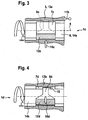
- FIG. 4 shown loading case of a radial bearing 1d of those according to FIG. 3 in that an axle bolt 14b is acted upon by a radial load 10d resting against it.
- a bearing seat 7d of constant width is applied to a hub 13b rotating about the axle bolt 14b, while a bearing seat 8d of the axle bolt 14b is subjected to point load and has a circumferentially variable width, by the bearing seat 8d starting from a load zone 12d (shown dotted) outside this is significantly tapered.
- rolling bearing 9 is here formed between the bearing seats 7d and 8d, a hydrodynamic sliding bearing 15 as a bearing means.
- the sliding bearing 15 in the other load cases according to the Figures 1-3 find use as storage means.
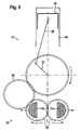
- the in FIG. 1 can be described among other things in the in FIG. 5 principle illustrated device 16 occur.
- This device 16 serves to compensate for second-order mass forces of a reciprocating internal combustion engine 17 in the form of a four-cylinder series (Lancaster compensation), which is illustrated by means of a transmission scheme.
- the reciprocating internal combustion engine 17 comprises a piston 18 which oscillates in a cylinder 18 and whose longitudinal movement is converted via a connecting rod 20 into a rotation of a crankshaft 21.
- the crankshaft 21 drives via an intermediate shaft 22 two imbalance shafts 23 with the imbalances 11a, wherein the unbalanced shafts 23 rotate in opposite directions parallel to the crankshaft 21 with double crankshaft speed.
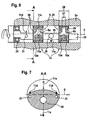
- each needle sleeve 25 is dimensioned so that it corresponds to a maximum width 26 of the associated bearing seat 8a in the region of its load zone 12a, while a minimum width 27 of the bearing seat 8a outside the load zone 12a is significantly smaller than the length of the needles 28 of the needle sleeve 25 is formed. Since only a non-pressurized lubricant mist is provided within the housing 2a, the lubrication conditions at the locally and temporarily protruding needles 28 can be significantly improved.
- the imbalance 11a of the imbalance shaft 23 acting in the direction of the arrow is based on an eccentric to its longitudinal axis 5 and in FIG. 6 Its eccentricity results from Freiappelisme 30 on the outer circumference of the imbalance shaft 23, which are based on the center of mass 29 partially or completely beyond the longitudinal axis 5. Since the claws 30 directly adjoin the bearing seats 8a, the tapering of the bearing seats 8a beyond the longitudinal axis 5 leads both to an advantageous mass reduction and to an additional imbalance 11c with respect to an imbalance shaft with bearing seats of constant width.
- this additional unbalance 11 c can be used in a bandwidth that is between the limiting cases of improved mass balance by maximum increase in imbalance 11 a while reducing mass of imbalance shaft 23 on the one hand and a maximum mass reduction at constant imbalance 11th a of the imbalance shaft 23 on the other hand extends.
- a constructive design in the region of the second limit case is represented symbolically in the present embodiment in the form of an imbalance 11 d compensating the additional imbalance 11 c.
- the compensating imbalance 11 d as at least a pair of unbalance u mirror-symmetrical cladding 31 formed. These are located outside of the bearing seats 8a and on the center of mass 29 at least predominantly located on this side of the longitudinal axis 5 on the outer circumference of the unbalanced shaft 23 and thus act in the opposite direction to the imbalance 11a of the center of mass 29.
- the claws 31 With regard to the maximum mass reduction of the imbalance shaft 23, it is expedient to arrange the claws 31 in the vicinity of a plane E, which is spanned by the longitudinal axis 5 and a direction v orthogonal to the unbalance direction u.
- the free seams 31 arranged there have a comparatively small effective eccentricity relative to the longitudinal axis 5, so that their negative-acting mass in the unbalance direction u can be selected correspondingly large in favor of the mass reduction of the imbalance shaft 23 at a constant degree of compensation.
Abstract
Description
Die Erfindung betrifft eine Radiallagerung einer in einem Gehäuse gelagerten Welle, welches Gehäuse und welche Welle um eine gemeinsame Längsachse relativ zueinander rotieren. Die Radiallagerung umfasst einen Lagersitz, der sich über einen Umfang von 360° erstreckt, relativ zu einer den Lagersitz in einer Lastzone beaufschlagenden Radiallast im wesentlichen stillsteht und in Richtung der Längsachse eine über dessen Umfang veränderliche Breite aufweist derart, dass der Lagersitz ausgehend von der Lastzone außerhalb der Lastzone deutlich verjüngt ist.The invention relates to a radial bearing of a shaft mounted in a housing, which housing and which shaft rotate about a common longitudinal axis relative to each other. The radial bearing comprises a bearing seat which extends over a circumference of 360 °, relative to a radial load acting on the bearing seat in a load zone substantially stationary and in the direction of the longitudinal axis has a variable width over its circumference such that the bearing seat starting from the load zone is significantly tapered outside the load zone.
Eine Radiallagerung einer Unwuchtwelle mit den Merkmalen das Oberbegriffs das Anspruchs 1 ist aus der gattungsgemäßen
In der
Ein solcher Belastungsfall der Radiallagerung ist im Stand der Technik grundsätzlich und im Falle der Wälzlagerung unter dem Begriff der sogenannten Punktlast bekannt, bei welcher die Radiallast in Abhängigkeit der Bewegungsverhältnisse gegenüber dem Innenring oder dem Außenring des Wälzlagers im wesentlichen still steht. Im Gegensatz dazu handelt es sich bei der sogenannten Umfangslast um einen Belastungsfall, bei welcher die Radiallast gegenüber dem Innenring oder dem Außenring des Wälzlagers rotiert. Mit dem Begriff "im wesentlichen" soll an dieser Stelle zum Ausdruck gebracht werden, dass die Radiallast aufgrund dynamischer Einflüsse streng genommen nicht punktförmig wirkt, sondern eine gewisse radiale Schwankungsbreite aufweisen kann.Such a load case of the radial bearing is known in the art in principle and in the case of rolling bearing the term of the so-called point load, in which the radial load in dependence of the movement conditions relative to the inner ring or the outer ring of the bearing is substantially stationary. In contrast, in the so-called circumferential load is a load case in which the radial load relative to the inner ring or the outer ring of the bearing rotates. The term "substantially" is intended to express at this point that the radial load is strictly speaking not punctiform due to dynamic influences, but may have a certain radial fluctuation range.
Die von der auf dem Lagersitz ruhenden Lastzone zu übertragenden Kräfte infolge der Radiallast sind ein wesentliches Kriterium für eine lebensdauerfeste Dimensionierung der Breite des Lagersitzes. Dieses Kriterium spielt jedoch für die erforderliche Breite außerhalb der Lastzone eine nur noch untergeordnete Rolle, da hier der Lagersitz einer deutlich geringeren und im Einzelfall gar keiner mechanischen Belastung mehr unterworfen ist. Dennoch sind im Stand der Technik bekannte Lagersitze rotationssymmetrisch mit konstanter Breite ausgebildet und daher für den hier vorliegenden Belastungsfall der Punktlast hinsichtlich der mechanischen Belastbarkeit außerhalb der Lastzone überdimensioniert. Hieraus können sich wesentliche Nachteile dahingehend ergeben, dass der herstellbedingt meist erhaben ausgebildete Lagersitz eine sowohl technisch und finanziell unerwünschte als auch vermeidbare Masse außerhalb der Lastzone mitführt. Gleichzeitig führt dies zu einem unnötig hohen Bearbeitungsaufwand des Lagersitzes, der auch außerhalb der Lastzone vollständig über seine konstante Breite fein zu bearbeiten ist.The forces to be transmitted by the load zone resting on the bearing seat as a result of the radial load are an essential criterion for a life-long dimensioning of the width of the bearing seat. However, this criterion plays only a minor role for the required width outside the load zone, since here the bearing seat is subject to a much lower and no mechanical load in any particular case. Nevertheless, in the prior art known bearing seats are rotationally symmetrical with constant width and therefore oversized for the present load case of the point load in terms of mechanical load capacity outside the load zone. This can result in significant disadvantages to the effect that the manufacturer's usually sublime trained bearing seat carries a both technically and financially undesirable and avoidable mass outside the load zone. At the same time, this leads to an unnecessarily high processing cost of the bearing seat, which is to be processed completely outside the load zone over its constant width fine.
Aufgabe der Erfindung ist daher, eine Radiallagerung der eingangs genannten Art so auszugestalten, dass die zitierten Nachteile mit einfachen Mitteln beseitigt sind. Dabei soll die Gestaltung der Radiallagerung insbesondere zu Gewichts- und Kostenvorteilen gegenüber im Stand der Technik bekannten Lagerungen führen.The object of the invention is therefore to provide a radial bearing of the type mentioned in such a way that the cited disadvantages are eliminated by simple means. The design of the radial bearing should lead in particular to weight and cost advantages over known in the art bearings.
Erfindungsgemäß wird diese Aufgabe dadurch gelöst, dass die Welle als Unwuchtwelle und der Lagersitz veränderlicher Breite an der Unwuchtwelle ausgebildet sind. Dabei läuft die Radiallast mit der Unwuchtwelle um, deren zur Längsachse exzentrisch angeordneter Massenschwerpunkt aus einer oder mehreren Freinehmungen am Außenumfang der Unwuchtwelle resultiert. Die Freinehmungen verlaufen, auf den Massenschwerpunkt der Unwuchtwelle bezogen, teilweise oder vollständig jenseits der Längsachse der Unwuchtwelle und grenzen an den Lagersitz veränderlicher Breite unmittelbar an.According to the invention, this object is achieved in that the shaft are designed as imbalance shaft and the bearing seat of variable width on the imbalance shaft. In this case, the radial load to the imbalance wave, the eccentric center of gravity to the longitudinal axis arranged mass center of gravity results from one or more claws on the outer circumference of the imbalance shaft. The claddings run, based on the center of gravity of the imbalance shaft, partially or completely beyond the longitudinal axis of the imbalance shaft and immediately adjacent to the bearing seat of variable width.
Zur Radiallagerung der Unwuchtwelle ist zumindest ein als Nadellager ohne Innenring und vorzugsweise als Nadelhülse ausgebildetes Wälzlager vorgesehen.For radial mounting of the imbalance shaft is at least designed as a needle bearing without inner ring and preferably designed as a needle roller bearing.
Bei diesem Belastungsfall handelt es sich um eine definierte, mit der Welle umlaufende Unwucht, die durch den Lagersitz veränderlicher Breite bei gleichzeitiger Massenreduzierung der Welle vorteilhaft verstärkt werden kann.In this load case is a defined, with the shaft rotating unbalance, which can be advantageously enhanced by the bearing seat variable width while reducing the mass of the shaft.
Mit einer so ausgebildeten Radiallagerung wird der Umstand optimal berücksichtigt, dass der mit Punktlast beaufschlagte Lagersitz außerhalb der Lastzone erheblich verjüngt werden und somit das Potenzial bekannter Lagerungen zur Reduzierung von rotativ bewegter Masse, Gewicht, Bearbeitungsaufwand und Kosten ausgeschöpft werden können, ohne die Funktionseigenschaften der Radiallagerung zu beeinträchtigen. Eine solche Beeinträchtigung wäre erst dann gegeben, wenn aufgrund der Verjüngung des Lagersitzes eine kritische Lagersitzbreite erreicht wird, unterhalb derer eine Dauerfestigkeit der Radiallagerung nicht mehr gewährleistet ist. Entscheidendes Kriterium hierfür kann im Falle einer als hydrodynamisches Gleitlager ausgebildeten Radiallagerung ein nicht mehr tragfähiger Schmierfilm oder im Falle des Wälzlagers eine unzulässig hohe Belastung des Lagersitzes außerhalb der Lastzone sein.With a radial bearing thus formed, the fact is optimally taken into account that the loaded with point load bearing seat outside the load zone are significantly tapered and thus the potential of known bearings to reduce rotationally moving mass, weight, processing costs and costs can be used without the functional properties of the radial bearing to impair. Such an impairment would only be given if a critical bearing seat width is reached due to the taper of the bearing seat, below which a fatigue strength of the radial bearing is no longer guaranteed. The decisive criterion for this, in the case of a radial bearing designed as a hydrodynamic slide bearing, may be a lubricating film which is no longer capable of bearing or, in the case of the rolling bearing, an unacceptably high load of the bearing seat outside the load zone.
Mit einer derart ausgebildeten Unwuchtwelle kann der zumeist bestehende Zielkonflikt einer kleinstmöglichen Masse bei größtmöglicher Unwucht der Welle besonders vorteilhaft gelöst werden. Dies liegt im wesentlichen darin begründet, dass sich die Freinehmungen nunmehr bis an den verjüngten Lagersitz hin erstrecken und gleichsam als erhöhte negative Masse zur Verstärkung der Unwucht genutzt werden können. Dennoch eröffnet sich gegenüber herkömmlichen Wellen mit Lagersitzen konstanter Breite nicht nur die Möglichkeit, die Unwucht der Welle bei gleichzeitiger Massenreduzierung zu erhöhen. Vielmehr ist im Falle einer unveränderten Unwucht eine darüber noch erheblich hinausgehende Massenreduzierung der Welle dadurch möglich, dass die ursprüngliche Unwuchterhöhung durch weitere, die Masse reduzierende Freinehmungen kompensiert wird, die auf den Massenschwerpunkt bezogen jedoch diesseits der Längsachse an der Unwuchtwelle anzuordnen sind. Selbstverständlich kann auch eine zwischen diesen beiden Grenzfällen angesiedelte Abstimmung der Unwuchtwelle gefunden werden, je nachdem, ob der Auslegungsschwerpunkt eher auf einer moderaten Massenreduzierung bei deutlicher Unwuchterhöhung oder eher auf einer deutlichen Massenreduzierung bei unveränderter Unwuchterhöhung liegt.With an imbalance shaft designed in this way, the mostly existing conflict of objectives of a smallest possible mass can be achieved particularly advantageously with the greatest possible imbalance of the shaft. This is essentially due to the fact that the claws now extend as far as the tapered bearing seat and can be used, as it were, as an increased negative mass to amplify the imbalance. Nonetheless, in comparison with conventional shafts with constant width bearing seats, it is not only possible to increase the imbalance of the shaft while at the same time reducing mass. Rather, in the case of an unchanged unbalance beyond even more substantial mass reduction of the wave is possible that the original Unwuchterhöhung is compensated by further, the mass reducing Freinehmungen, based on the center of gravity but on this side of the longitudinal axis to be arranged on the unbalanced shaft. Of course, a settled between these two border cases tuning the imbalance shaft can be found, depending on whether the design focus is more on a moderate mass reduction with significant imbalance increase or rather on a significant mass reduction with unchanged unbalance increase.
In Weiterbildung der Erfindung soll die Unwuchtwelle zu einer Vorrichtung zum Ausgleich von Massenkräften und/oder Massenmomenten einer Hubkolben-Brennkraftmaschine mit einer parallel zur Längsachse der Unwuchtwelle angeordneten und die Unwuchtwelle zumindest mittelbar antreibenden Kurbelwelle der Hubkolben-Brennkraftmaschine gehören. Eine derartige Ausgleichsvorrichtung ist dem Fachmann auf dem Gebiet von Hubkolben-Brennkraftmaschinen insbesondere in Reihen- oder V-Anordnung als wirksame Maßnahme zur Reduzierung von Schwingungen in Folge oszillierender Massenkräfte bekannt. Insbesondere bei Hubkolben-Brennkraftmaschinen für den Fahrzeugbereich steigen jedoch die Anforderungen an die Leichtbaugüte der Hubkolben-Brennkraftmaschine zunehmend, so dass sich vorgenannte Möglichkeiten zur Massenreduzierung der Unwuchtwelle für diesen Einsatzfall besonders vorteilhaft nutzen lassen. Das geringere Massenträgheitsmoment der Unwuchtwelle führt darüber hinaus zu einer verbesserten Dynamik der Hubkolben-Brennkraftmaschine, da einem hohen Drehzahlgradienten weniger Widerstand entgegengesetzt wird. Außerdem lässt sich insbesondere bei Dieselmotoren mit ausgeprägten Drehschwingungen der Kurbelwelle im unteren Drehzahlbereich die mechanische Spitzenbelastung im Antriebsbereich der Ausgleichsvorrichtung mit verringertem Trägheitsmoment der Unwuchtwelle absenken.In a further development of the invention, the imbalance shaft to a device for balancing inertial forces and / or inertial moments of a reciprocating internal combustion engine with a parallel to the longitudinal axis of the imbalance shaft arranged and the imbalance shaft at least indirectly driving crankshaft of the reciprocating internal combustion engine belong. Such a compensating device is known to those skilled in the field of reciprocating internal combustion engines, in particular in a series or V arrangement as an effective measure for reducing vibrations due to oscillating mass forces. However, especially in reciprocating internal combustion engines for the vehicle sector, the demands on the lightweight construction of the reciprocating internal combustion engine are increasing, so that the aforementioned possibilities for mass reduction of the imbalance shaft can be used particularly advantageously for this application. The lower mass moment of inertia of the imbalance shaft also leads to improved dynamics of the reciprocating internal combustion engine, since a high speed gradient is opposed to less resistance. In addition, in particular in diesel engines with pronounced torsional vibrations of the crankshaft in the lower speed range, the mechanical peak load in the drive region of the compensating device can be lowered with a reduced moment of inertia of the imbalance shaft.
Die vorgenannten Betrachtungen gelten in verstärktem Maße dann, wenn die Ausgleichsvorrichtung zwei Unwuchtwellen umfasst, die mit doppelter Kurbelwellendrehzahl gegenläufig rotieren. Diese dem Fachmann auch als Lancaster-Ausgleich bekannte Anordnung dient zum Ausgleich der freien Massenkräfte zweiter Ordnung bei einem Vierzylinder-Reihenmotor.The above considerations apply to a greater extent when the compensation device comprises two imbalance shafts, which rotate in opposite directions with double crankshaft speed. This known to those skilled in the art as Lancaster compensation arrangement is used to compensate for the free mass forces of second order in a four-cylinder in-line engine.
Zur Radiallagerung der Unwuchtwelle ist zumindest ein als Nadellager ohne Innenring und vorzugsweise als Nadelhülse ausgebildetes Wälzlager vorgesehen ist. Neben den günstigen Reibungseigenschaften des Wälzlagers gegenüber einem hydrodynamischen Gleitlager, das insbesondere bei tiefen Temperaturen und/oder hochviskosem Hydraulikmittel zu erheblichen Reibleistungsverlusten im Antrieb der Unwuchtwelle führen kann, lassen sich die Vorteile der Massenreduzierung und/oder der Unwuchterhöhung der Unwuchtwelle durch deren als Nadellagerung ausgebildete Radiallagerung noch weiter ausbauen, da der von einem Nadellager umfasste Lagersitz in der Regel stärker verjüngt werden kann, als es im Falle des hydrodynamischen Gleitlagers unter Berücksichtigung eines tragfähigen Schmierfilms möglich wäre. So erlaubt vor allem die Verwendung einer Nadelhülse, die dem Fachmann als Baueinheit kleinster radialer Bauhöhe mit spanlos geformtem Außenring und einem Nadelkranz bekannt ist, eine besonders Bauraum sparende und kostengünstige Radiallagerung der Unwuchtwelle bei ausreichender Dauerfestigkeit.For radial mounting of the imbalance shaft is at least designed as a needle bearing without inner ring and preferably designed as a needle roller bearing is provided. In addition to the favorable friction properties of the rolling bearing against a hydrodynamic sliding bearing, which can lead to considerable friction losses in the drive of the unbalance shaft, especially at low temperatures and / or high viscosity hydraulic fluid, the advantages of mass reduction and / or unbalance increase the imbalance shaft by their trained as a needle bearing radial bearing even further, since the bearing seat encompassed by a needle bearing can usually be tapered more strongly than would be possible in the case of the hydrodynamic slide bearing taking into account a load-bearing lubricating film. Thus, especially the use of a needle sleeve, which is known to the expert as a unit smallest radial height with non-cutting outer ring and a needle ring, a particularly space-saving and cost-effective radial bearing of the imbalance shaft with sufficient fatigue strength.
In weiterer Ausgestaltung der Erfindung kann es schließlich vorteilhaft sein, dass die Breite des Nadellagers im wesentlichen einer maximalen Breite des dem Nadellager zugeordneten Lagersitzes veränderlicher Breite entspricht, während eine minimale Breite des Lagersitzes kleiner als die Länge der Nadeln des Nadellagers ausgebildet ist. Gleichzeitig soll zur Schmierung des Nadellagers lediglich ein druckloser Schmiermittelnebel vorgesehen sein. Mit dieser Ausgestaltung der Erfindung lassen sich die Schmierbedingungen am Nadellager dadurch verbessern, dass die über den Lagersitz lokal und temporär überstehenden Nadeln dem drucklosen Schmiermittelnebel verstärkt ausgesetzt sind. Umgekehrt kann dies auch einem Austritt von abrasiven Partikeln aus dem Laufbahnbereich des Nadellagers zugunsten einer erhöhten Verschleißfestigkeit der Radiallagerung förderlich sein. Um im Bereich der minimalen Breite des Lagersitzes dessen vollständigen Längskontakt mit den Nadeln zu gewährleisten, ist bei dieser Ausgestaltung die Verwendung eines einreihigen Nadellagers gegenüber der eines mehrreihigen Nadellagers zu bevorzugen.In a further embodiment of the invention, it may finally be advantageous that the width of the needle bearing substantially corresponds to a maximum width of the needle bearing associated bearing seat variable width, while a minimum width of the bearing seat is smaller than the length of the needles of the needle bearing. At the same time, only an unpressurized lubricant mist should be provided for lubrication of the needle bearing. With this embodiment of the invention, the lubrication conditions on the needle roller bearing can be improved by exposing the needles that are locally and temporarily projecting beyond the bearing seat to the pressureless lubricant mist. Conversely, this can also be beneficial for a discharge of abrasive particles from the raceway region of the needle bearing in favor of increased wear resistance of the radial bearing. In order to ensure its full longitudinal contact with the needles in the region of the minimum width of the bearing seat, the use of a single-row needle bearing with respect to a multi-row needle bearing is to be preferred in this embodiment.
Weitere Merkmale der Erfindung ergeben sich aus der nachfolgenden Beschreibung und aus den Zeichnungen, in denen die erfindungsgemäße Radiallagerung und Radiallagerungen bei anderen Belastungsfällen jeweils grundlegend sowie eine erfindungsgemäße Radiallagerung beispielhaft anhand einer Unwuchtwelle einer Vorrichtung zum Massenausgleich einer Hubkolbenbrennmaschine vereinfacht dargestellt sind. Es zeigen:
- Figur 1
- die Radiallagerung für den erfindungsgemäßen Belastungsfall in schematischer Darstellung;
- Figur 2
- eine Radiallagerung für einen zweiten Belastungsfall in schematischer Darstellung;
Figur 3- eine Radiallagerung für einen dritten Belastungsfall in schematischer Darstellung;
- Figur 4
- eine Radiallagerung für einen vierten Belastungsfall in schematischer Darstellung;
Figur 5- die Vorrichtung zum Massenausgleich einer HubkolbenBrennkraftmaschine in schematischer Darstellung;
Figur 6- eine der Unwuchtwellen aus
Figur 5 - Figur 7
- den Schnitt AA aus
Figur 6
- FIG. 1
- the radial bearing for the load case according to the invention in a schematic representation;
- FIG. 2
- a radial bearing for a second load case in a schematic representation;
- FIG. 3
- a radial bearing for a third load case in a schematic representation;
- FIG. 4
- a radial bearing for a fourth load case in a schematic representation;
- FIG. 5
- the apparatus for mass balance of a reciprocating internal combustion engine in a schematic representation;
- FIG. 6
- one of the imbalance waves
FIG. 5 in simplified longitudinal representation; - FIG. 7
- the cut AA
FIG. 6 in an enlarged view.
In
Der in
Bei dem in
Schließlich unterscheidet sich der in
Der in
Die Lagerung einer dieser Unwuchtwellen 23 geht detaillierter aus deren Längsdarstellung gemäß
Die in Pfeilrichtung wirkende Unwucht 11a der Unwuchtwelle 23 basiert auf einem zu ihrer Längsachse 5 exzentrischen und in
Eine konstruktive Auslegung im Bereich des zweiten Grenzfalls ist in dem vorliegenden Ausführungsbeispiel in Form einer die zusätzliche Unwucht 11 c kompensierenden Unwucht 11 d symbolhaft dargestellt. Wie auch aus
- 1 a,b,c,d1 a, b, c, d
- Radiallagerungradial bearing
- 2a,b2a, b
- Gehäusecasing
- 33
- Außenteilouter part
- 4a,b4a, b
- Wellewave
- 55
- Längsachselongitudinal axis
- 66
- Innenteilinner part
- 7a,b,c,d7a, b, c, d
- Lagersitzbearing seat
- 8a,b,c,d8a, b, c, d
- Lagersitzbearing seat
- 99
- Wälzlagerroller bearing
- 10a,b,c,d10a, b, c, d
- Radiallastradial load
- 11 a,b,c,d11 a, b, c, d
- Unwuchtunbalance
- 12a,b,c,d12a, b, c, d
- Lastzoneload zone
- 13a,b13a, b
- Nabehub
- 14a,b14a, b
- Achsbolzenaxle
- 1515
- Gleitlagerbearings
- 1616
- Vorrichtungcontraption
- 1717
- Hubkolben-BrennkraftmaschineReciprocating internal combustion engine
- 1818
- Zylindercylinder
- 1919
- Kolbenpiston
- 2020
- Pleuelpleuel
- 2121
- Kurbelwellecrankshaft
- 2222
- Zwischenwelleintermediate shaft
- 2323
- Unwuchtwelleunbalanced shaft
- 2424
- Kugellagerball-bearing
- 2525
- Nadelhülseneedle sleeve
- 2626
- maximale Breitemaximum width
- 2727
- minimale Breiteminimum width
- 2828
- Nadelneedle
- 2929
- MassenschwerpunktCenter of gravity
- 3030
- FreinehmungFreinehmung
- 3131
- FreinehmungFreinehmung
- Ee
- Ebenelevel
- uu
- Unwuchtrichtungunbalance direction
- vv
- zur Unwucht orthogonale Richtungto unbalance orthogonal direction
Claims (2)
- Radial mounting (1a) of a shaft (4a) mounted in a housing, which housing (2a) and which shaft (4a) rotate in relation to each other about a common longitudinal axis (5), the radial mounting (1a) comprising a bearing seat (8a) which extends over a circumference of 360°, remains substantially stationary in relation to a radial load (10a) that acts on the bearing seat (8a) in a load zone (12a) and has a width that varies over its circumference in the direction of the longitudinal axis (5) in such a way that, starting from the load zone (12a), the bearing seat (8a) tapers significantly outside the load zone (12a), wherein the shaft (4a) is formed as an eccentric shaft (23) and the bearing seat (8a) of variable width is formed on the eccentric shaft (23) and wherein the radial load (10a) rotates with the eccentric shaft (23), the centre of mass (29) of which, which is arranged eccentrically in relation to the longitudinal axis (5), results from one or more recesses (30) on the outer circumference of the eccentric shaft (23), which recesses (30) extend partially or completely on the opposite side of the longitudinal axis (5) of the eccentric shaft (23), with respect to the centre of mass (29) of the eccentric shaft (23), and directly adjoin the bearing seat (8a) of variable width, characterized in that at least one rolling bearing (9) formed as a needle bearing without an inner race, and preferably as a needle bush (25), is provided for the radial mounting (1a) of the eccentric shaft (23).
- Radial mounting according to Claim 1, characterized in that the width of the needle bearing (25) corresponds substantially to a maximum width (26) of the bearing seat (8a) of variable width assigned to the needle bearing (25), while a minimum width (27) of the bearing seat (8a) is formed less than the length of the needles (28) of the needle bearing (25), a pressureless lubricant mist being all that is provided for the lubrication of the needle bearing.
Priority Applications (7)
| Application Number | Priority Date | Filing Date | Title |
|---|---|---|---|
| DE202006020558U DE202006020558U1 (en) | 2005-10-13 | 2006-08-16 | radial bearing |
| PL08017547T PL2017486T3 (en) | 2005-10-13 | 2006-08-16 | Radial bearing |
| PL06118986T PL1775484T5 (en) | 2005-10-13 | 2006-08-16 | Radial bearing |
| DE202006020559U DE202006020559U1 (en) | 2005-10-13 | 2006-08-16 | radial bearing |
| EP08017532.6A EP2014935B2 (en) | 2005-10-13 | 2006-08-16 | Radial bearing |
| PL08017532T PL2014935T5 (en) | 2005-10-13 | 2006-08-16 | Radial bearing |
| EP08017547.4A EP2017486B2 (en) | 2005-10-13 | 2006-08-16 | Radial bearing |
Applications Claiming Priority (1)
| Application Number | Priority Date | Filing Date | Title |
|---|---|---|---|
| US72625305P | 2005-10-13 | 2005-10-13 |
Related Child Applications (6)
| Application Number | Title | Priority Date | Filing Date |
|---|---|---|---|
| EP08017547.4A Division EP2017486B2 (en) | 2005-10-13 | 2006-08-16 | Radial bearing |
| EP08017547.4A Previously-Filed-Application EP2017486B2 (en) | 2005-10-13 | 2006-08-16 | Radial bearing |
| EP08017547.4A Division-Into EP2017486B2 (en) | 2005-10-13 | 2006-08-16 | Radial bearing |
| EP08017532.6A Division EP2014935B2 (en) | 2005-10-13 | 2006-08-16 | Radial bearing |
| EP08017532.6A Previously-Filed-Application EP2014935B2 (en) | 2005-10-13 | 2006-08-16 | Radial bearing |
| EP08017532.6A Division-Into EP2014935B2 (en) | 2005-10-13 | 2006-08-16 | Radial bearing |
Publications (4)
| Publication Number | Publication Date |
|---|---|
| EP1775484A2 EP1775484A2 (en) | 2007-04-18 |
| EP1775484A3 EP1775484A3 (en) | 2008-10-08 |
| EP1775484B1 EP1775484B1 (en) | 2009-12-30 |
| EP1775484B2 true EP1775484B2 (en) | 2016-01-20 |
Family
ID=37607212
Family Applications (3)
| Application Number | Title | Priority Date | Filing Date |
|---|---|---|---|
| EP08017547.4A Not-in-force EP2017486B2 (en) | 2005-10-13 | 2006-08-16 | Radial bearing |
| EP08017532.6A Active EP2014935B2 (en) | 2005-10-13 | 2006-08-16 | Radial bearing |
| EP06118986.6A Active EP1775484B2 (en) | 2005-10-13 | 2006-08-16 | Radial bearing |
Family Applications Before (2)
| Application Number | Title | Priority Date | Filing Date |
|---|---|---|---|
| EP08017547.4A Not-in-force EP2017486B2 (en) | 2005-10-13 | 2006-08-16 | Radial bearing |
| EP08017532.6A Active EP2014935B2 (en) | 2005-10-13 | 2006-08-16 | Radial bearing |
Country Status (9)
| Country | Link |
|---|---|
| US (2) | US7628133B2 (en) |
| EP (3) | EP2017486B2 (en) |
| JP (1) | JP5288086B2 (en) |
| KR (1) | KR101313927B1 (en) |
| CN (3) | CN101457708B (en) |
| AT (3) | ATE453806T1 (en) |
| DE (6) | DE502006005770D1 (en) |
| ES (3) | ES2337105T5 (en) |
| PL (3) | PL1775484T5 (en) |
Cited By (1)
| Publication number | Priority date | Publication date | Assignee | Title |
|---|---|---|---|---|
| DE102018125866B3 (en) | 2018-10-18 | 2019-06-27 | Schaeffler Technologies AG & Co. KG | unbalanced shaft |
Families Citing this family (25)
| Publication number | Priority date | Publication date | Assignee | Title |
|---|---|---|---|---|
| DE102007009800A1 (en) * | 2006-04-18 | 2007-10-25 | Herzog Intertec Gmbh | balancer shaft |
| DE102007027989A1 (en) | 2007-06-14 | 2008-12-18 | Herzog Intertec Gmbh | balancer shaft |
| DE102007027990A1 (en) | 2007-06-14 | 2008-12-18 | Herzog Intertec Gmbh | balancer shaft |
| DE102007037287A1 (en) | 2007-08-07 | 2009-02-12 | Schaeffler Kg | Mass balancing device for a reciprocating internal combustion engine |
| DE102008060084A1 (en) * | 2008-12-02 | 2010-06-10 | Schaeffler Kg | balancer shaft |
| JP5190348B2 (en) | 2008-12-22 | 2013-04-24 | 株式会社音戸工作所 | Engine balancer equipment |
| DE102009031064A1 (en) | 2009-06-30 | 2011-01-05 | Schaeffler Technologies Gmbh & Co. Kg | Bearing arrangement with a shaft and a needle bearing |
| DE102009035112A1 (en) | 2009-07-29 | 2011-02-03 | Schaeffler Technologies Gmbh & Co. Kg | unbalanced shaft |
| US8939123B2 (en) | 2009-07-30 | 2015-01-27 | Herzog Intertec Gmbh | Countershaft |
| DE102009036067A1 (en) * | 2009-08-04 | 2011-02-10 | Schaeffler Technologies Gmbh & Co. Kg | Method for producing a balancing shaft |
| DE102009036794A1 (en) | 2009-08-08 | 2011-02-10 | Schaeffler Technologies Gmbh & Co. Kg | Mass balancing mechanism |
| DE102010046156B4 (en) | 2009-10-08 | 2022-01-05 | Schaeffler Technologies AG & Co. KG | Mass balancing gear and method for its assembly |
| DE102009057634A1 (en) * | 2009-12-09 | 2011-06-16 | Schaeffler Technologies Gmbh & Co. Kg | Radial roller bearings, in particular for roller bearings of shafts in internal combustion engines |
| DE102010046163A1 (en) * | 2010-09-21 | 2012-03-22 | Magna Powertrain Ag & Co. Kg | Mass balance unit |
| DE102011087535A1 (en) | 2011-12-01 | 2013-06-06 | Mahle International Gmbh | balancer shaft |
| DE102014214004B4 (en) * | 2014-07-18 | 2019-10-10 | Aktiebolaget Skf | Radial bearing, especially for an imbalance shaft |
| DE102014213996B4 (en) * | 2014-07-18 | 2017-08-24 | Aktiebolaget Skf | Rolling bearings with an inclined tread |
| DE102014214001B4 (en) | 2014-07-18 | 2019-12-19 | Aktiebolaget Skf | Rolling bearings with line contact and lubricant channel |
| CN104817581B (en) * | 2015-05-07 | 2018-01-02 | 衢州学院 | A kind of siliceous dihydric phenol and preparation method thereof |
| GB2544738A (en) * | 2015-11-24 | 2017-05-31 | Perkins Engines Co Ltd | Oil sump assembly for an engine |
| DE102016001541A1 (en) | 2016-02-10 | 2016-10-27 | Daimler Ag | Unbalance shaft, in particular for a motor vehicle |
| DE102017208237A1 (en) | 2017-05-16 | 2018-11-22 | Aktiebolaget Skf | Manufacturing method of a bearing ring and radial bearing assembly, which is equipped with such a bearing ring, in particular for a balance shaft |
| DE102017112895B4 (en) | 2017-06-12 | 2022-09-29 | Hirschvogel Umformtechnik Gmbh | Balance shaft and balance shaft assembly |
| US10663033B2 (en) | 2017-07-12 | 2020-05-26 | American Axle & Manufacturing, Inc. | Balance shaft having reduced mass and inertia |
| DE102017212688A1 (en) | 2017-07-24 | 2019-01-24 | Aktiebolaget Skf | Bearing cage, radial bearing arrangement with such a cage, in particular for a balance shaft |
Citations (6)
| Publication number | Priority date | Publication date | Assignee | Title |
|---|---|---|---|---|
| EP0243683A1 (en) † | 1986-04-15 | 1987-11-04 | IVECO FIAT S.p.A. | Internal combustion engine provided with a pair of rotary eccentric masses arranged to dynamically balance the engine |
| JPH09151993A (en) † | 1995-11-28 | 1997-06-10 | Honda Motor Co Ltd | Bearing part lubrication structure of balancer shaft |
| DE19835145A1 (en) † | 1998-08-04 | 2000-02-10 | Daimler Chrysler Ag | Tubular low cost automotive crankshaft mass balancing shaft is shrouded to reduce air noise or foaming of oil at high engine speeds |
| DE10257562A1 (en) † | 2002-12-10 | 2004-07-01 | Adam Opel Ag | Mass compensator for a vehicle combustion engine, has compensating shaft below crankshaft with through screws mounting bearing block onto engine block |
| JP2005016644A (en) † | 2003-06-26 | 2005-01-20 | Toyota Motor Corp | Balance shaft |
| WO2005093286A1 (en) † | 2004-03-23 | 2005-10-06 | Daimlerchrysler Ag | Balancer shaft for a multi-cylinder in-line engine |
Family Cites Families (29)
| Publication number | Priority date | Publication date | Assignee | Title |
|---|---|---|---|---|
| DE389786C (en) | 1924-02-07 | Josef Kirner Dr Ing | Rolling bearings | |
| FR1301919A (en) | 1961-07-11 | 1962-08-24 | Alsacienne Constr Meca | Improvement in the assembly of connecting rods on the connecting rod heads of cylinder engines in |
| FR95734E (en) * | 1966-11-15 | 1971-06-04 | Pitner Alfred | Needle bearing without clearance. |
| US3960419A (en) * | 1974-03-29 | 1976-06-01 | Thomas Scott Brawley | Bearing component |
| JPS55144240U (en) * | 1979-04-03 | 1980-10-16 | ||
| JPS5728914U (en) * | 1980-07-26 | 1982-02-16 | ||
| JPS5932687A (en) * | 1982-08-13 | 1984-02-22 | Mitsubishi Electric Corp | Scroll compressor |
| FR2533274A1 (en) | 1982-09-16 | 1984-03-23 | Coussinets Ste Indle | METHOD FOR REDUCING THE ENERGY CONSUMPTION OF BEARINGS |
| DE3326467A1 (en) * | 1983-07-22 | 1985-01-31 | Schaab, Brigitta, 8950 Kaufbeuren | Piston and connecting rod arrangement |
| JPH0515609Y2 (en) * | 1987-03-18 | 1993-04-23 | ||
| JP2859270B2 (en) | 1987-06-11 | 1999-02-17 | 旭光学工業株式会社 | Camera gaze direction detection device |
| JPS646644A (en) | 1987-06-26 | 1989-01-11 | Toshiba Corp | Heating apparatus for bath water |
| FR2619881B1 (en) † | 1987-08-31 | 1990-01-19 | Peugeot | BALANCING SHAFT FOR A RECIPROCATING PISTON ENGINE |
| DE3733982A1 (en) | 1987-10-08 | 1989-04-20 | Kloeckner Humboldt Deutz Ag | Trapezoidal connecting rod |
| DE3813029A1 (en) | 1988-04-19 | 1989-11-02 | Kloeckner Humboldt Deutz Ag | Connecting rod |
| CN2035817U (en) * | 1988-06-18 | 1989-04-12 | 史玉琏 | Multicylinder diesel engine balanced means |
| US5000140A (en) * | 1989-10-20 | 1991-03-19 | Caterpillar Inc. | Isolated thrust pin for use with a rotating shaft |
| BR9400717A (en) * | 1994-03-08 | 1995-10-24 | Metal Leve Sa | Articulating pin for two-piece plunger |
| JPH0828570A (en) | 1994-07-22 | 1996-02-02 | Nissan Motor Co Ltd | Main bearing structure for crankshaft for internal combustion engine |
| DE59610358D1 (en) | 1996-07-17 | 2003-05-28 | Maag Pump Systems Ag Zuerich | Slide bearing for a shaft |
| DE19828847B4 (en) | 1998-06-27 | 2005-12-01 | Federal-Mogul Wiesbaden Gmbh & Co. Kg | Piston pin bushing |
| DE19926406A1 (en) | 1999-06-10 | 2000-12-14 | Schaeffler Waelzlager Ohg | Main bearing for a crankshaft or a camshaft of an internal combustion engine comprises an elastic ring which surrounds the two half bushings of the bearing and clamps them against the rolling elements with a preload |
| CA2316152C (en) | 1999-09-03 | 2004-10-05 | Honda Giken Kogyo Kabushiki Kaisha | Balance shaft for engine balancing systems |
| DE10029950A1 (en) * | 2000-06-26 | 2002-01-03 | Volkswagen Ag | connecting rod |
| US6616338B2 (en) * | 2001-06-13 | 2003-09-09 | Emerson Power Transmission Manufacturing, L.P. | Extended load zone bearing |
| CN1164861C (en) * | 2002-03-14 | 2004-09-01 | 孔维忠 | Direct drive type reciprocating piston IC engine |
| JP3906754B2 (en) * | 2002-07-12 | 2007-04-18 | トヨタ自動車株式会社 | Crank bearing |
| US7051696B2 (en) * | 2003-09-30 | 2006-05-30 | Honda Motor Co., Ltd. | Bearing structure of crankshaft in internal combustion engine |
| US7322750B1 (en) * | 2005-11-18 | 2008-01-29 | Ronnie Besselman | Locking engine bearing splay cap |
-
2006
- 2006-08-16 EP EP08017547.4A patent/EP2017486B2/en not_active Not-in-force
- 2006-08-16 DE DE502006005770T patent/DE502006005770D1/en active Active
- 2006-08-16 PL PL06118986T patent/PL1775484T5/en unknown
- 2006-08-16 PL PL08017532T patent/PL2014935T5/en unknown
- 2006-08-16 DE DE502006005811T patent/DE502006005811D1/en active Active
- 2006-08-16 EP EP08017532.6A patent/EP2014935B2/en active Active
- 2006-08-16 DE DE502006005814T patent/DE502006005814D1/en active Active
- 2006-08-16 DE DE202006020559U patent/DE202006020559U1/en not_active Expired - Lifetime
- 2006-08-16 PL PL08017547T patent/PL2017486T3/en unknown
- 2006-08-16 ES ES08017532.6T patent/ES2337105T5/en active Active
- 2006-08-16 DE DE202006020558U patent/DE202006020558U1/en not_active Expired - Lifetime
- 2006-08-16 AT AT06118986T patent/ATE453806T1/en active
- 2006-08-16 DE DE202006020120U patent/DE202006020120U1/en not_active Expired - Lifetime
- 2006-08-16 AT AT08017532T patent/ATE453807T1/en active
- 2006-08-16 AT AT08017547T patent/ATE453808T1/en active
- 2006-08-16 EP EP06118986.6A patent/EP1775484B2/en active Active
- 2006-08-16 ES ES08017547T patent/ES2337106T3/en active Active
- 2006-08-16 ES ES06118986.6T patent/ES2337076T5/en active Active
- 2006-10-10 JP JP2006276488A patent/JP5288086B2/en active Active
- 2006-10-12 KR KR1020060099100A patent/KR101313927B1/en active IP Right Grant
- 2006-10-12 US US11/548,727 patent/US7628133B2/en not_active Ceased
- 2006-10-13 CN CN2008101895174A patent/CN101457708B/en active Active
- 2006-10-13 CN CN2006101361888A patent/CN1955500B/en active Active
- 2006-10-13 CN CN2008101895140A patent/CN101469645B/en active Active
-
2016
- 2016-11-08 US US15/345,891 patent/USRE46845E1/en active Active
Patent Citations (6)
| Publication number | Priority date | Publication date | Assignee | Title |
|---|---|---|---|---|
| EP0243683A1 (en) † | 1986-04-15 | 1987-11-04 | IVECO FIAT S.p.A. | Internal combustion engine provided with a pair of rotary eccentric masses arranged to dynamically balance the engine |
| JPH09151993A (en) † | 1995-11-28 | 1997-06-10 | Honda Motor Co Ltd | Bearing part lubrication structure of balancer shaft |
| DE19835145A1 (en) † | 1998-08-04 | 2000-02-10 | Daimler Chrysler Ag | Tubular low cost automotive crankshaft mass balancing shaft is shrouded to reduce air noise or foaming of oil at high engine speeds |
| DE10257562A1 (en) † | 2002-12-10 | 2004-07-01 | Adam Opel Ag | Mass compensator for a vehicle combustion engine, has compensating shaft below crankshaft with through screws mounting bearing block onto engine block |
| JP2005016644A (en) † | 2003-06-26 | 2005-01-20 | Toyota Motor Corp | Balance shaft |
| WO2005093286A1 (en) † | 2004-03-23 | 2005-10-06 | Daimlerchrysler Ag | Balancer shaft for a multi-cylinder in-line engine |
Non-Patent Citations (8)
| Title |
|---|
| "Reibleistungsreduktion Konstruktive Maßnahmen zur Verbrauchseinsparung", FORSCHUNG TRIBOLOGIE, pages 592 - 597 † |
| "Technologie Highlights aus dem FEV-Arbeitsspektrum", FEV-SPECTRUM, 23 April 2003 (2003-04-23), pages 1 - 8 † |
| BEITZ W. ET AL: "Dubble - Taschenbuch für den Maschninenbau", vol. 14, 1981, SPRINGER-VERLAG, BERLIN - HEIDELBERG - NEW YORK, pages: 425 - 427 † |
| Bericht ATZ-Online, "BMW R 1200 GS: Boxermotor mit Ausgleichswelle", 13. Januar 2004 † |
| BRÄNDLEIN ET AL.: "Die Wälzlagerpraxis - Handbuch für die Berechnung und Gestaltung von Lagerungen", vol. 2, 1998, VEREINIGTE FACHVERLAGE GMBH, MAINZ, pages: 1-21 - 320-321 † |
| DOHMEN J. DIPL.-ING.: "Untersuchungen zum reibungsoptimierten Triebwerk an Pkw-Verbernnungsmotoren", 2003 † |
| JP 2005 016 644 A und zugehörige englische Übersetzung † |
| SOLFRANK P.: "Neues erreichen mit "alten" Techniken", WÄLZLAGER IM HUBKOLBENMOTOR, 2010, pages 288 - 301 † |
Cited By (2)
| Publication number | Priority date | Publication date | Assignee | Title |
|---|---|---|---|---|
| DE102018125866B3 (en) | 2018-10-18 | 2019-06-27 | Schaeffler Technologies AG & Co. KG | unbalanced shaft |
| WO2020078512A1 (en) | 2018-10-18 | 2020-04-23 | Schaeffler Technologies AG & Co. KG | Unbalanced shaft |
Also Published As
Similar Documents
| Publication | Publication Date | Title |
|---|---|---|
| EP1775484B2 (en) | Radial bearing | |
| EP2449273B1 (en) | Bearing arrangement with an unbalanced shaft and a needle bearing | |
| EP2282080B1 (en) | Counterbalancing gear | |
| DE102008026204A1 (en) | Bearing arrangement of a shaft | |
| EP2134985B1 (en) | Mass equalizer transmission of an internal combustion engine | |
| DE60216425T2 (en) | AUSGLEICHSWELLE ASSEMBLY | |
| EP2185838B1 (en) | Mass balancing device for a reciprocating piston internal combustion engine | |
| EP1222411B1 (en) | Compensating shaft assembly for piston engines | |
| DE202007011678U1 (en) | balancer shaft | |
| WO2014040595A1 (en) | Unbalanced shaft | |
| AT516036B1 (en) | Mass balance unit | |
| EP2373908B1 (en) | Balancing shaft | |
| DE102005049705A1 (en) | Roller bearing comprises shaft mounted in housing, between which rollers are mounted, bearing seat passing through shaft which is wider in zone subjected to most force | |
| EP2140169B1 (en) | Method for the production of a drop-forged balancing shaft | |
| DE102008015135A1 (en) | Bearing area for shaft device of stroke piston-internal-combustion engine of vehicle, has material recess of unbalanced shaft filled outer-extensively with smaller, specific weight of foreign material component | |
| DE102018115429B4 (en) | Unbalance shaft | |
| DE102009050628B4 (en) | Device for compensating for the second-order inertial forces for an in-line piston internal combustion engine | |
| DE102018119524B4 (en) | Process for the formation of a system of balancer shaft and bearing or bearing ring | |
| DE102008053801A1 (en) | Crankshaft for internal combustion engine of motor vehicle, has secondary mass rotatably supported at crankshaft over damping element, where rotational axis of secondary mass is arranged in distance to rotational axis of crankshaft | |
| DE102005042122A1 (en) | Multi-cylinder stroke-piston internal combustion engine`s e.g. four-cylinder internal combustion engine, free mass forces partially balancing device, has rotary crankshaft provided, where balancing mass supports directly at crankshaft |
Legal Events
| Date | Code | Title | Description |
|---|---|---|---|
| PUAI | Public reference made under article 153(3) epc to a published international application that has entered the european phase |
Free format text: ORIGINAL CODE: 0009012 |
|
| AK | Designated contracting states |
Kind code of ref document: A2 Designated state(s): AT BE BG CH CY CZ DE DK EE ES FI FR GB GR HU IE IS IT LI LT LU LV MC NL PL PT RO SE SI SK TR |
|
| AX | Request for extension of the european patent |
Extension state: AL BA HR MK YU |
|
| 17P | Request for examination filed |
Effective date: 20070823 |
|
| PUAL | Search report despatched |
Free format text: ORIGINAL CODE: 0009013 |
|
| AK | Designated contracting states |
Kind code of ref document: A3 Designated state(s): AT BE BG CH CY CZ DE DK EE ES FI FR GB GR HU IE IS IT LI LT LU LV MC NL PL PT RO SE SI SK TR |
|
| AX | Request for extension of the european patent |
Extension state: AL BA HR MK RS |
|
| RIC1 | Information provided on ipc code assigned before grant |
Ipc: F16C 19/44 20060101ALI20080904BHEP Ipc: F16C 33/66 20060101ALI20080904BHEP Ipc: F16C 33/58 20060101ALI20080904BHEP Ipc: F16C 9/02 20060101AFI20070118BHEP |
|
| AKX | Designation fees paid |
Designated state(s): AT BE BG CH CY CZ DE DK EE ES FI FR GB GR HU IE IS IT LI LT LU LV MC NL PL PT RO SE SI SK TR |
|
| GRAP | Despatch of communication of intention to grant a patent |
Free format text: ORIGINAL CODE: EPIDOSNIGR1 |
|
| GRAS | Grant fee paid |
Free format text: ORIGINAL CODE: EPIDOSNIGR3 |
|
| GRAA | (expected) grant |
Free format text: ORIGINAL CODE: 0009210 |
|
| AK | Designated contracting states |
Kind code of ref document: B1 Designated state(s): AT BE BG CH CY CZ DE DK EE ES FI FR GB GR HU IE IS IT LI LT LU LV MC NL PL PT RO SE SI SK TR |
|
| REG | Reference to a national code |
Ref country code: GB Ref legal event code: FG4D Free format text: NOT ENGLISH |
|
| REG | Reference to a national code |
Ref country code: CH Ref legal event code: EP |
|
| REG | Reference to a national code |
Ref country code: IE Ref legal event code: FG4D |
|
| REF | Corresponds to: |
Ref document number: 502006005770 Country of ref document: DE Date of ref document: 20100211 Kind code of ref document: P |
|
| REG | Reference to a national code |
Ref country code: RO Ref legal event code: EPE |
|
| REG | Reference to a national code |
Ref country code: SE Ref legal event code: TRGR |
|
| REG | Reference to a national code |
Ref country code: ES Ref legal event code: FG2A Ref document number: 2337076 Country of ref document: ES Kind code of ref document: T3 |
|
| PG25 | Lapsed in a contracting state [announced via postgrant information from national office to epo] |
Ref country code: FI Free format text: LAPSE BECAUSE OF FAILURE TO SUBMIT A TRANSLATION OF THE DESCRIPTION OR TO PAY THE FEE WITHIN THE PRESCRIBED TIME-LIMIT Effective date: 20091230 Ref country code: LT Free format text: LAPSE BECAUSE OF FAILURE TO SUBMIT A TRANSLATION OF THE DESCRIPTION OR TO PAY THE FEE WITHIN THE PRESCRIBED TIME-LIMIT Effective date: 20091230 |
|
| REG | Reference to a national code |
Ref country code: NL Ref legal event code: VDEP Effective date: 20091230 |
|
| REG | Reference to a national code |
Ref country code: SK Ref legal event code: T3 Ref document number: E 6829 Country of ref document: SK |
|
| RAP2 | Party data changed (patent owner data changed or rights of a patent transferred) |
Owner name: SCHAEFFLER TECHNOLOGIES GMBH & CO. KG |
|
| LTIE | Lt: invalidation of european patent or patent extension |
Effective date: 20091230 |
|
| PG25 | Lapsed in a contracting state [announced via postgrant information from national office to epo] |
Ref country code: LV Free format text: LAPSE BECAUSE OF FAILURE TO SUBMIT A TRANSLATION OF THE DESCRIPTION OR TO PAY THE FEE WITHIN THE PRESCRIBED TIME-LIMIT Effective date: 20091230 Ref country code: SI Free format text: LAPSE BECAUSE OF FAILURE TO SUBMIT A TRANSLATION OF THE DESCRIPTION OR TO PAY THE FEE WITHIN THE PRESCRIBED TIME-LIMIT Effective date: 20091230 |
|
| REG | Reference to a national code |
Ref country code: IE Ref legal event code: FD4D |
|
| REG | Reference to a national code |
Ref country code: HU Ref legal event code: AG4A Ref document number: E007585 Country of ref document: HU |
|
| PG25 | Lapsed in a contracting state [announced via postgrant information from national office to epo] |
Ref country code: EE Free format text: LAPSE BECAUSE OF FAILURE TO SUBMIT A TRANSLATION OF THE DESCRIPTION OR TO PAY THE FEE WITHIN THE PRESCRIBED TIME-LIMIT Effective date: 20091230 Ref country code: BG Free format text: LAPSE BECAUSE OF FAILURE TO SUBMIT A TRANSLATION OF THE DESCRIPTION OR TO PAY THE FEE WITHIN THE PRESCRIBED TIME-LIMIT Effective date: 20100330 Ref country code: PT Free format text: LAPSE BECAUSE OF FAILURE TO SUBMIT A TRANSLATION OF THE DESCRIPTION OR TO PAY THE FEE WITHIN THE PRESCRIBED TIME-LIMIT Effective date: 20100430 Ref country code: NL Free format text: LAPSE BECAUSE OF FAILURE TO SUBMIT A TRANSLATION OF THE DESCRIPTION OR TO PAY THE FEE WITHIN THE PRESCRIBED TIME-LIMIT Effective date: 20091230 Ref country code: IS Free format text: LAPSE BECAUSE OF FAILURE TO SUBMIT A TRANSLATION OF THE DESCRIPTION OR TO PAY THE FEE WITHIN THE PRESCRIBED TIME-LIMIT Effective date: 20100430 |
|
| PLBI | Opposition filed |
Free format text: ORIGINAL CODE: 0009260 |
|
| PG25 | Lapsed in a contracting state [announced via postgrant information from national office to epo] |
Ref country code: IE Free format text: LAPSE BECAUSE OF FAILURE TO SUBMIT A TRANSLATION OF THE DESCRIPTION OR TO PAY THE FEE WITHIN THE PRESCRIBED TIME-LIMIT Effective date: 20091230 Ref country code: CY Free format text: LAPSE BECAUSE OF FAILURE TO SUBMIT A TRANSLATION OF THE DESCRIPTION OR TO PAY THE FEE WITHIN THE PRESCRIBED TIME-LIMIT Effective date: 20091230 Ref country code: GR Free format text: LAPSE BECAUSE OF FAILURE TO SUBMIT A TRANSLATION OF THE DESCRIPTION OR TO PAY THE FEE WITHIN THE PRESCRIBED TIME-LIMIT Effective date: 20100331 |
|
| PLAX | Notice of opposition and request to file observation + time limit sent |
Free format text: ORIGINAL CODE: EPIDOSNOBS2 |
|
| 26 | Opposition filed |
Opponent name: HERZOG INTERTEC GMBH Effective date: 20100930 |
|
| PG25 | Lapsed in a contracting state [announced via postgrant information from national office to epo] |
Ref country code: DK Free format text: LAPSE BECAUSE OF FAILURE TO SUBMIT A TRANSLATION OF THE DESCRIPTION OR TO PAY THE FEE WITHIN THE PRESCRIBED TIME-LIMIT Effective date: 20091230 |
|
| BERE | Be: lapsed |
Owner name: SCHAEFFLER K.G. Effective date: 20100831 |
|
| PLBB | Reply of patent proprietor to notice(s) of opposition received |
Free format text: ORIGINAL CODE: EPIDOSNOBS3 |
|
| PG25 | Lapsed in a contracting state [announced via postgrant information from national office to epo] |
Ref country code: MC Free format text: LAPSE BECAUSE OF NON-PAYMENT OF DUE FEES Effective date: 20100831 |
|
| REG | Reference to a national code |
Ref country code: CH Ref legal event code: PL |
|
| PG25 | Lapsed in a contracting state [announced via postgrant information from national office to epo] |
Ref country code: LI Free format text: LAPSE BECAUSE OF NON-PAYMENT OF DUE FEES Effective date: 20100831 Ref country code: CH Free format text: LAPSE BECAUSE OF NON-PAYMENT OF DUE FEES Effective date: 20100831 |
|
| REG | Reference to a national code |
Ref country code: GB Ref legal event code: 732E Free format text: REGISTERED BETWEEN 20110407 AND 20110413 |
|
| PG25 | Lapsed in a contracting state [announced via postgrant information from national office to epo] |
Ref country code: BE Free format text: LAPSE BECAUSE OF NON-PAYMENT OF DUE FEES Effective date: 20100831 |
|
| RAP2 | Party data changed (patent owner data changed or rights of a patent transferred) |
Owner name: SCHAEFFLER TECHNOLOGIES AG & CO. KG |
|
| APBM | Appeal reference recorded |
Free format text: ORIGINAL CODE: EPIDOSNREFNO |
|
| APBP | Date of receipt of notice of appeal recorded |
Free format text: ORIGINAL CODE: EPIDOSNNOA2O |
|
| APAH | Appeal reference modified |
Free format text: ORIGINAL CODE: EPIDOSCREFNO |
|
| PG25 | Lapsed in a contracting state [announced via postgrant information from national office to epo] |
Ref country code: LU Free format text: LAPSE BECAUSE OF NON-PAYMENT OF DUE FEES Effective date: 20100816 |
|
| REG | Reference to a national code |
Ref country code: DE Ref legal event code: R081 Ref document number: 502006005770 Country of ref document: DE Owner name: SCHAEFFLER TECHNOLOGIES AG & CO. KG, DE Free format text: FORMER OWNER: SCHAEFFLER TECHNOLOGIES GMBH & CO. KG, 91074 HERZOGENAURACH, DE Effective date: 20120828 Ref country code: DE Ref legal event code: R081 Ref document number: 502006005770 Country of ref document: DE Owner name: SCHAEFFLER TECHNOLOGIES GMBH & CO. KG, DE Free format text: FORMER OWNER: SCHAEFFLER TECHNOLOGIES GMBH & CO. KG, 91074 HERZOGENAURACH, DE Effective date: 20120828 |
|
| APBQ | Date of receipt of statement of grounds of appeal recorded |
Free format text: ORIGINAL CODE: EPIDOSNNOA3O |
|
| PG25 | Lapsed in a contracting state [announced via postgrant information from national office to epo] |
Ref country code: TR Free format text: LAPSE BECAUSE OF FAILURE TO SUBMIT A TRANSLATION OF THE DESCRIPTION OR TO PAY THE FEE WITHIN THE PRESCRIBED TIME-LIMIT Effective date: 20091230 |
|
| REG | Reference to a national code |
Ref country code: AT Ref legal event code: PC Ref document number: 453806 Country of ref document: AT Kind code of ref document: T Owner name: SCHAEFFLER TECHNOLOGIES AG & CO. KG, DE Effective date: 20130920 |
|
| RAP2 | Party data changed (patent owner data changed or rights of a patent transferred) |
Owner name: SCHAEFFLER TECHNOLOGIES GMBH & CO. KG |
|
| REG | Reference to a national code |
Ref country code: DE Ref legal event code: R081 Ref document number: 502006005770 Country of ref document: DE Owner name: SCHAEFFLER TECHNOLOGIES GMBH & CO. KG, DE Free format text: FORMER OWNER: SCHAEFFLER TECHNOLOGIES AG & CO. KG, 91074 HERZOGENAURACH, DE Effective date: 20140217 Ref country code: DE Ref legal event code: R081 Ref document number: 502006005770 Country of ref document: DE Owner name: SCHAEFFLER TECHNOLOGIES AG & CO. KG, DE Free format text: FORMER OWNER: SCHAEFFLER TECHNOLOGIES AG & CO. KG, 91074 HERZOGENAURACH, DE Effective date: 20140217 |
|
| REG | Reference to a national code |
Ref country code: HU Ref legal event code: FH1C Free format text: FORMER REPRESENTATIVE(S): MESZAROSNE DONUSZ KATALIN, S.B.G & K. SZABADALMI UEGYVIVOEI IRODA, HU Representative=s name: SBGK SZABADALMI UEGYVIVOEI IRODA, HU Ref country code: HU Ref legal event code: GB9C Owner name: SCHAEFFLER TECHNOLOGIES GMBH & CO. KG, DE Free format text: FORMER OWNER(S): SCHAEFFLER KG, DE |
|
| RAP2 | Party data changed (patent owner data changed or rights of a patent transferred) |
Owner name: SCHAEFFLER TECHNOLOGIES AG & CO. KG |
|
| REG | Reference to a national code |
Ref country code: DE Ref legal event code: R081 Ref document number: 502006005770 Country of ref document: DE Owner name: SCHAEFFLER TECHNOLOGIES AG & CO. KG, DE Free format text: FORMER OWNER: SCHAEFFLER TECHNOLOGIES GMBH & CO. KG, 91074 HERZOGENAURACH, DE Effective date: 20150213 |
|
| REG | Reference to a national code |
Ref country code: ES Ref legal event code: PC2A Owner name: SCHAEFFLER TECHNOLOGIES AG & CO.KG Effective date: 20150512 |
|
| REG | Reference to a national code |
Ref country code: HU Ref legal event code: FH1C Free format text: FORMER REPRESENTATIVE(S): SBGK SZABADALMI UEGYVIVOEI IRODA, HU Representative=s name: SBGK SZABADALMI UEGYVIVOEI IRODA, HU Ref country code: HU Ref legal event code: GB9C Owner name: SCHAEFFLER TECHNOLOGIES AG & CO. KG, DE Free format text: FORMER OWNER(S): SCHAEFFLER KG, DE; SCHAEFFLER TECHNOLOGIES GMBH & CO. KG, DE |
|
| APBU | Appeal procedure closed |
Free format text: ORIGINAL CODE: EPIDOSNNOA9O |
|
| REG | Reference to a national code |
Ref country code: AT Ref legal event code: PC Ref document number: 453806 Country of ref document: AT Kind code of ref document: T Owner name: SCHAEFFLER TECHNOLOGIES AG & CO. KG, DE Effective date: 20150602 |
|
| REG | Reference to a national code |
Ref country code: FR Ref legal event code: PLFP Year of fee payment: 10 |
|
| PUAH | Patent maintained in amended form |
Free format text: ORIGINAL CODE: 0009272 |
|
| STAA | Information on the status of an ep patent application or granted ep patent |
Free format text: STATUS: PATENT MAINTAINED AS AMENDED |
|
| 27A | Patent maintained in amended form |
Effective date: 20160120 |
|
| AK | Designated contracting states |
Kind code of ref document: B2 Designated state(s): AT BE BG CH CY CZ DE DK EE ES FI FR GB GR HU IE IS IT LI LT LU LV MC NL PL PT RO SE SI SK TR |
|
| REG | Reference to a national code |
Ref country code: DE Ref legal event code: R102 Ref document number: 502006005770 Country of ref document: DE |
|
| REG | Reference to a national code |
Ref country code: ES Ref legal event code: DC2A Ref document number: 2337076 Country of ref document: ES Kind code of ref document: T5 Effective date: 20160408 |
|
| REG | Reference to a national code |
Ref country code: SE Ref legal event code: RPEO |
|
| REG | Reference to a national code |
Ref country code: FR Ref legal event code: PLFP Year of fee payment: 11 |
|
| REG | Reference to a national code |
Ref country code: FR Ref legal event code: PLFP Year of fee payment: 12 |
|
| REG | Reference to a national code |
Ref country code: FR Ref legal event code: PLFP Year of fee payment: 13 |
|
| REG | Reference to a national code |
Ref country code: SK Ref legal event code: TC4A Ref document number: E 6829 Country of ref document: SK Owner name: SCHAEFFLER TECHNOLOGIES AG & CO. KG, HERZOGENA, DE Effective date: 20221012 Ref country code: SK Ref legal event code: T5 Ref document number: E 6829 Country of ref document: SK Ref country code: SK Ref legal event code: PC4A Ref document number: E 6829 Country of ref document: SK Owner name: SCHAEFFLER TECHNOLOGIES GMBH & CO. KG, HERZOGE, DE Free format text: FORMER OWNER: SCHAEFFLER KG, HERZOGENAURACH, DE Effective date: 20221012 |
|
| P01 | Opt-out of the competence of the unified patent court (upc) registered |
Effective date: 20230522 |
|
| PGFP | Annual fee paid to national office [announced via postgrant information from national office to epo] |
Ref country code: RO Payment date: 20230803 Year of fee payment: 18 Ref country code: IT Payment date: 20230825 Year of fee payment: 18 Ref country code: GB Payment date: 20230822 Year of fee payment: 18 Ref country code: CZ Payment date: 20230807 Year of fee payment: 18 Ref country code: AT Payment date: 20230822 Year of fee payment: 18 |
|
| PGFP | Annual fee paid to national office [announced via postgrant information from national office to epo] |
Ref country code: SK Payment date: 20230803 Year of fee payment: 18 Ref country code: SE Payment date: 20230821 Year of fee payment: 18 Ref country code: PL Payment date: 20230721 Year of fee payment: 18 Ref country code: HU Payment date: 20230823 Year of fee payment: 18 Ref country code: FR Payment date: 20230823 Year of fee payment: 18 |
|
| PGFP | Annual fee paid to national office [announced via postgrant information from national office to epo] |
Ref country code: ES Payment date: 20231027 Year of fee payment: 18 |
|
| PGFP | Annual fee paid to national office [announced via postgrant information from national office to epo] |
Ref country code: DE Payment date: 20231019 Year of fee payment: 18 |