EP1775455A2 - Auto ignition engine with combustion chambers for high pressure ignition - Google Patents
Auto ignition engine with combustion chambers for high pressure ignition Download PDFInfo
- Publication number
- EP1775455A2 EP1775455A2 EP20060019137 EP06019137A EP1775455A2 EP 1775455 A2 EP1775455 A2 EP 1775455A2 EP 20060019137 EP20060019137 EP 20060019137 EP 06019137 A EP06019137 A EP 06019137A EP 1775455 A2 EP1775455 A2 EP 1775455A2
- Authority
- EP
- European Patent Office
- Prior art keywords
- cooled plate
- internal combustion
- combustion engine
- engine according
- cylinder
- Prior art date
- Legal status (The legal status is an assumption and is not a legal conclusion. Google has not performed a legal analysis and makes no representation as to the accuracy of the status listed.)
- Granted
Links
Images


Classifications
-
- F—MECHANICAL ENGINEERING; LIGHTING; HEATING; WEAPONS; BLASTING
- F02—COMBUSTION ENGINES; HOT-GAS OR COMBUSTION-PRODUCT ENGINE PLANTS
- F02F—CYLINDERS, PISTONS OR CASINGS, FOR COMBUSTION ENGINES; ARRANGEMENTS OF SEALINGS IN COMBUSTION ENGINES
- F02F1/00—Cylinders; Cylinder heads
- F02F1/24—Cylinder heads
- F02F1/26—Cylinder heads having cooling means
- F02F1/36—Cylinder heads having cooling means for liquid cooling
- F02F1/40—Cylinder heads having cooling means for liquid cooling cylinder heads with means for directing, guiding, or distributing liquid stream
-
- F—MECHANICAL ENGINEERING; LIGHTING; HEATING; WEAPONS; BLASTING
- F02—COMBUSTION ENGINES; HOT-GAS OR COMBUSTION-PRODUCT ENGINE PLANTS
- F02F—CYLINDERS, PISTONS OR CASINGS, FOR COMBUSTION ENGINES; ARRANGEMENTS OF SEALINGS IN COMBUSTION ENGINES
- F02F1/00—Cylinders; Cylinder heads
- F02F1/02—Cylinders; Cylinder heads having cooling means
- F02F1/10—Cylinders; Cylinder heads having cooling means for liquid cooling
- F02F1/16—Cylinder liners of wet type
-
- F—MECHANICAL ENGINEERING; LIGHTING; HEATING; WEAPONS; BLASTING
- F01—MACHINES OR ENGINES IN GENERAL; ENGINE PLANTS IN GENERAL; STEAM ENGINES
- F01P—COOLING OF MACHINES OR ENGINES IN GENERAL; COOLING OF INTERNAL-COMBUSTION ENGINES
- F01P3/00—Liquid cooling
- F01P3/12—Arrangements for cooling other engine or machine parts
- F01P3/14—Arrangements for cooling other engine or machine parts for cooling intake or exhaust valves
-
- F—MECHANICAL ENGINEERING; LIGHTING; HEATING; WEAPONS; BLASTING
- F02—COMBUSTION ENGINES; HOT-GAS OR COMBUSTION-PRODUCT ENGINE PLANTS
- F02F—CYLINDERS, PISTONS OR CASINGS, FOR COMBUSTION ENGINES; ARRANGEMENTS OF SEALINGS IN COMBUSTION ENGINES
- F02F1/00—Cylinders; Cylinder heads
- F02F1/24—Cylinder heads
- F02F2001/249—Cylinder heads with flame plate, e.g. insert in the cylinder head used as a thermal insulation between cylinder head and combustion chamber
Definitions
- the invention relates to a self-igniting internal combustion engine with combustion chambers for high ignition pressures according to the preamble of claim 1.
- the invention is based on the assumption that the combustion chamber seal usual today must be taken over by the underside of the cylinder head in future engines with greatly increased ignition pressures of a separate component. It is a arranged between the combustion chamber and the cylinder head the top surface of the combustion chamber forming separate, with the crankcase and / or the cylinder liner positively and gastight connected cooled plate in which the valve seats at least one inlet valve and at least one outlet valve are arranged and the is penetrated by the at least one injection valve.
- the advantage of such a component is, on the one hand, that the positive connection of the cooled plate with the crankcase and / or the cylinder liner can be made directly to the combustion chamber boundary, whereby the deflection at pressurization already considerably minimized compared to today's standard cylinder heads due to the much smaller spans
- the use of this separate from the crankcase, cylinder head and possibly the cylinder liner component opens up completely new possibilities in terms of material selection.
- the cooling of the cooled plate is carried out by the cooling medium provided for the cooling of the crankcase and the cylinder head, so that the cooled plate can be advantageously integrated into the existing cooling system.
- a further advantage of the cooled plate according to the invention is that, due to the better accessibility for the mechanical processing, cooling channels can be introduced into the cooled plate which permit a significantly improved cooling of the combustion chamber roof and the valve seats compared to conventional cylinder heads.
- the cooling channels can be advantageously formed as outgoing from the peripheral side of the cooled plate holes, which advantageously extend in the cooled plate that they cut other holes and form a connected system of holes. In this case, at least some of the bores are reclosed towards the peripheral side in order to simplify advantageously the inflow and outflow of the coolant.
- the supply of the cooled plate with coolant can be done easily and thus advantageously so that in the peripheral side and / or in the protruding edge region of the top surface of the combustion chamber forming flat side of the cooled plate and / or the top surface opposite flat side of the cooled plate inflow and / / or outflow openings are provided and the supply of the cooled plate with coolant directly and / or via the crankcase and / or via the cylinder head. This opens up the possibility of optimally adapting the coolant flow to the respective structural conditions.
- the cooled plate according to the invention can be used both in bushing-free combustion chambers and in combustion chambers which have a sleeve arranged in a cylinder bore.
- a socket it is particularly advantageous to use one which has a collar which is supported on a balcony in the cylinder bore.
- the inflow and outflow openings in the cooled plate are formed as bores corresponding to corresponding openings in the cylinder head or in the collar of the bush or in the crankcase or in a separate coolant manifold and the cooling channels in Connect the cooled plate to the coolant chambers in the cylinder head, crankcase or separate coolant manifold.
- sealing means can be provided in each case in the crossing area, which reliably prevent leakage of the cooling medium.
- the outer diameter of the inner diameter of the Combustion chamber substantially corresponds to the cylindrical projection is in the assembled state in the interior of the cylinder bore or the socket, so that the cooled plate engages the upper edge of the combustion chamber angle. It is particularly conducive to the seal to choose the diameter of the cylindrical projection so that there is an interference fit between it and the combustion chamber diameter. In addition, it may be advantageous for sealing the combustion chamber to provide a seal between the combustion chamber overlapping part of the cooled plate and the crankcase or the Buchsenbund.
- connection of the cooled plate with the crankcase or, if present, the bushing collar is advantageously accomplished by screwing the cooled plate to the crankcase or the bushing collar by means of screws, the screws are advantageous as close to the combustion chamber edge to arrange the deflection of the cooled plate during the Minimize ignition events.
- combustion chambers having a socket, by means of an internal thread on the upper edge of the sleeve and an external thread on the circumference of the cylindrical extension to screw the cooled plate to the socket, so that the connection between the socket and the cooled plate in particularly favorable manner takes place directly on the combustion chamber edge.
- Another simple and therefore cheap way to connect the cooled plate with the socket consists of welding these two components together.
- the cooled plate may be provided on its side facing the combustion chamber with a coating of low thermal conductivity and / or high wear resistance, wherein the coating with low thermal conductivity minimizes the heat loss of the combustion chamber gas and thus advantageously increases the efficiency and a wear-reducing coating on the valve seats positively influences the service life.
- both the cooling channels and the coolant supply and coolant discharges can be particularly simple and therefore advantageous by z.
- the cylinder head which adjoins the cooled plate on the side facing away from the combustion chamber, can be designed as a cylinder head assigned to a cylinder or as a continuous cylinder head assigned to several or all cylinders and contains, in addition to the gas exchange channels, at least one injection valve and the guides for the inlet cylinder head. and exhaust valves.
- the cylinder head is advantageously configured to pressurize the cooled plate at least in the region of its center.
- the coolant chambers are divided, extending at least perpendicular to the flat side of the cooled plate bulkheads, which derive particular occurring in the center of the cooled plate forces in the cylinder head fasteners in the crankcase.
- the use of the cooled plate according to the invention opens up possibilities of material selection with respect to the cylinder head, which did not exist in conventional internal combustion engines for commercial vehicles for reasons of strength, then light metal alloys can be used for the cylinder head, which reduce the weight in an advantageous manner and have much better properties with respect to the Heat transport have.
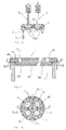
- a control and actuation module For controlling and actuating the gas exchange valves and the injection valves, a control and actuation module is provided which extends over a plurality of cylinders, preferably over all cylinders of a series engine or over all cylinders of a cylinder bank of a V-engine and which contains at least one camshaft and the actuators for the gas exchange valves and encloses the actuators for the injectors.
- the control and actuation module is connected to the lubricant circuit and has a housing cover, via which the actuators for the gas exchange valves and the injectors are accessible.
- control and actuation module fastened by means of detachable connections to the cylinder head or the cylinder heads, the construction detached from the cylinder head offers new possibilities in the choice of material.
- a complete or at least partial execution in plastic allows an advantageous weight reduction and simplifies the production as a plastic injection molded part.
- the control and actuation module can advantageously an all combustion chambers or integrated all the combustion chambers of a cylinder bank common charge air pipe.
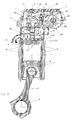
- Fig. 1 shows a combustion chamber 1 of a self-igniting internal combustion engine, which consists of a cylinder liner 2, a piston 3 and a cooled plate 4.
- the cylinder liner 2 is arranged in a known manner in the crankcase 5 and surrounded in the region of the combustion chamber 1 by coolant leading rooms 6 for cooling the combustion chamber walls.
- the piston 3 acts via a connecting rod 7 on a crankshaft 8, which is mounted in the crankcase 5 is (not shown).
- the combustion chamber 1 is closed by the cooled plate 4, which essentially has the outer diameter of a bushing collar 9 arranged on the cylinder head end of the cylinder liner 2.
- a cylindrical projection 10 is arranged to the combustion chamber 1, the diameter of which substantially corresponds to the inner diameter of the cylinder liner 2, so that the cooled plate 4, the cylinder head side edge of the cylinder liner 2 engages angularly.
- cooling channels 11 Inside the cooled plate 4 cooling channels 11 are arranged, in which a cooling medium circulates.
- the cooled plate 4 is positively and gas-tightly connected to the cylinder liner 2.
- valve seats (not visible in Fig. 1) arranged, which cooperate with the valve plates 12 of the gas exchange valves 13.
- the fuel supply via an opening 20 which passes through the cooled plate 4 in its center from the side facing away from the combustion chamber 1 in the direction of the combustion chamber 1 and in which an injection valve (not shown in Fig. 1) is arranged.
- the arrangement of the injection valve in the opening 20 is made such that the injection valve, possibly with the interposition of a sealant, the combustion chamber gas-tight and with its injection nozzle opening (not shown) projects into it.
- the cylinder head 14 is fastened in a conventional manner by means of screws (not shown) which project through the cylinder head 14 in the direction of the crankcase 5 and fix it on the crankcase 5.
- the gas channels (not shown) for intake air or the combustion gases, the valve guides (not shown) for the valve stems 15 of the gas exchange valves 13 and a coolant space 16 for cooling the cylinder head 14 or its built-in parts are arranged in the cylinder head 14 in a known manner.
- the space in the cylinder head 14 is divided into a cellular structure, on the one hand by connecting holes 21 allows targeted coolant management and on the other hand, has a high rigidity, the a deflection of the cooled plate 4 counteracts in the ignition phase.
- FIG. 1 An external view of the cylinder liner 2 with attached cooled plate 4, Fig. 2 in side view and Fig. 3 in plan view.
- the cooled plate 4 is screwed to the bushing collar 9 by means of screws 19, and corresponds in diameter to the outer diameter
- the gas exchange valves 13 and the opening 20 are arranged for the injection valve.
- FIG. 5 shows a section along the line CC in FIG. 2. Starting from opposite sides of the circumference of the cooled plate 4, boreholes 11.1, 11.2, 11.5, 11.6 forming two pairs of bores run toward each other, wherein each of the pairs of bores has a " X ", so cut the holes of a hole pair.
- the arrangement of the bore pairs relative to the arrangement of the openings for the gas exchange valves 13, whose centers essentially form the vertices of a square, is made such that the intersection of a pair of holes between two adjacent openings for the gas exchange valves 13.
- the holes 11.1, 11.2, 11.5, 11.6 of each pair of holes extend from the respective points of intersection viewed in the direction of the center of the cooled plate 4 again apart and intersect the holes of the respective opposing hole pair on a line through the center of the cooled plate 4th
- the so-forming network of connected holes 11.1 - 11.6 forms the cooling channels 11 which, as will be explained in more detail below, can be connected in different ways with the cooling system of the internal combustion engine.
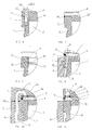
- the screw connection of the cylinder liner 2 to the cooled plate 4 described above in connection with FIGS. 1 to 5 is shown in a detail view in FIG. 6.
- the cooled plate 4 is located, the combustion chamber 1 in the direction of the cylinder head 14 (not shown in FIG. 6) finally, in the region of the bushing collar 9 on the cylinder liner 2 and surrounds the inner edge of the bushing collar 9 angle-shaped.
- the screw 19 cooperates with a corresponding thread 23 in the bushing collar 9 and sets the cooled plate 4 on the bushing collar 9.
- the diameter of the cylindrical projection 10 of the cooled plate 4 in conjunction with the inner diameter of the cylinder liner 2 can be designed so that there is an interference fit.
- FIG. 8 shows another way to screw the cooled plate 4 with the bushing collar 9, to the cylindrical projection 10 of the cooled plate 4, an external thread 25 is provided which cooperates with an internal thread 26 on the cylinder head side edge of the bushing collar 9.
- connection with Figures 6 to 8 between the cooled plate 4 and the cylinder liner are only examples, it can be with the skilled person available many different compounds between these two components, but in particular between the cooled plate and the Crankcase, in one embodiment of the combustion chamber without cylinder liner realize.
- cooling channels 11 forming holes 11.1-11.6 are connected to the cooling system of the internal combustion engine. This connection can be done in different ways. Some ways to feed the cooling channels 11 in the cooled plate 4 with coolant or to remove coolant therefrom are shown by way of example in the detailed illustrations in FIGS. 9-11.
- the sectional view in Fig. 9 shows this simplifies the already known arrangement of cooled plate 4 and cylinder liner 2.
- the cylinder liner 2 is located in the cylinder bore in the crankcase 5, wherein for cooling the walls of the combustion chamber 1 coolant leading spaces 6 between the crankcase 5 and cylinder liner 2 are formed.
- the cooled plate 4 has a bore 11 forming a cooling channel which extends from the peripheral side 27 of the cooled plate 4 radially inwardly. To the peripheral side 27 towards the cooling channel 11 is closed by means of a pressed ball 28.
- connection of the cooling channel 11 to the cooling system of the internal combustion engine is through a supply bore 29 accomplished, which passes through the bushing collar 9 of the cylinder liner 2 and is aligned with a connection bore 30 in resting on the bushing collar 9 edge region of the cooled plate 4, wherein the connection bore 30 opens into the cooling channel 11.
- a supply bore 29 accomplished, which passes through the bushing collar 9 of the cylinder liner 2 and is aligned with a connection bore 30 in resting on the bushing collar 9 edge region of the cooled plate 4, wherein the connection bore 30 opens into the cooling channel 11.
- similar feed bores and thus aligned connection bores may be provided at several points of the cooled plate 4 and cooperate with corresponding cooling channels to ensure efficient cooling.
- FIG. 10 A further possibility of supplying coolant from the crankcase 5 to the cooled plate 4 is shown schematically in a sectional drawing, FIG. 10.
- the already described arrangement of cylinder liner 2 and cooled plate 4 is shown.
- This arrangement is enclosed on the one hand by the crankcase 5 and the other hand arranged on the crankcase 5 cylinder head 14.
- In the crankcase 5 runs a connecting channel 31 from a arranged in the crankcase 5 coolant passage 32 to the dividing line between the cylinder head 14 and crankcase 5 and goes there in a cylinder head 14 arranged connection channel 33 via, which in turn via a connection opening 34 in the analogous to the example of FIG. 9 in the cooled plate 4 arranged cooling channel 11 opens.
- sealing means 35 are provided to seal the transition between the crankcase 5 and cylinder head 14 on the one hand and the cylinder head 14 and cooled plate 4 on the other hand.
- similar coolant supply to the cooled plate 4 may be provided at several points.
- FIG. 11 shows in simplified form a coolant supply to the cooled plate 4 from the cylinder head 14 of the internal combustion engine.
- the arrangement shown also in this case comprises a cylinder liner 2 with which the cooled plate 4 is connected in one of the ways described above.
- the combination of cylinder liner 2 and cooled plate 4 superimposed in a cylinder bore in the crankcase 5, such that the cylinder head side flat side of the cooled plate 4, with the cylinder head 14 adjacent side of the crankcase 5 is aligned.
- a connection between the coolant chamber 16 and the cooling channel 11 in the cooled plate 4 is provided by the coolant chamber 16 arranged in the cylinder head 14 via a connection opening 36 to be cooled on the cooled plate 4, which is in alignment with a coolant connection 37 in the cooled plate 4 created.
- the cooling channel 11 formed from the peripheral side of the cooled plate 4 and formed in the form of a bore is, as in the examples described above, by a pressed ball 28 near the peripheral side locked.
- a sealing means 35 is arranged around the coolant connection 37.
- several similar connections can be provided between the coolant chamber 16 in the cylinder head 14 and cooling channels 11 in the cooled plate 4.
- the coolant discharge from the cooled plate 4 to the crankcase 5 or to the cylinder head 14 may be similar to the coolant feeds described in the examples, so that a separate illustration of the coolant discharges can be waived.
- the above-described principles of the coolant supply of the cooled plate 4 are of course equally suitable for internal combustion engines with cylinder liners and bushingless internal combustion engines.
- FIGS. 12 and 13 shows a section along the line D-D (FIG. 5) and FIG. 13 shows a section along the line E-E (FIG. 5).
- Fig. 12 shows, starting from a first coolant chamber 16.1, which is part of the coolant chamber 16 in the cylinder head 14, an inlet bore 38 which connects the first coolant chamber 16.1 with the bore 11.1 in the cooled plate 4.
- the bore 11.1 which is closed to the narrow side of the cooled plate 4 through a ball 28, cuts at the point X, the bore 11.2 whose further course to the point Y in the sectional view is.
- the bore 11.2 intersects the bore 11.6 whose course is shown in the right half of FIG.
- the bore 11.6 cuts at the point Z the bore 11.5 and is closed on the narrow side of the cooled plate 4 with a pressed-in bore 11.6 ball 28.
- Via a drain hole 39 a connection between the bore 11.6 and a second coolant chamber 16.2 is made in the cylinder head 14, which is located downstream of the first coolant chamber 16.1 and also part of the coolant chamber 16.
- FIG. 13 shows a sectional view deviating from the illustration in FIG. 12 in FIG. 5 with EE.
- the bore 11.2 intersects both the bore 11.6 and the bore 11.3, whose course is shown in the right half of Fig. 13.
- the bore 11.3 is also closed near the peripheral side with a ball 28.
- a further drain hole 40 is provided which connects the bore 11.3 with a third coolant chamber 16.3 which is also part of the coolant chamber 16 and downstream of the coolant chamber 16.1.
- connections 21 between the individual parts of the coolant chamber 16 (FIG. 1) and the connections between the coolant chamber 16 and the cooling channels 11 are designed in this way are that a staggered according to the heat load of the cooled plate 4 and cylinder head 14 results in heat dissipation, while the heat load and thus the heat dissipation at the combustion chamber boundary is greatest and decreases with increasing distance from the combustion chamber.
- the cooled plate 4 may be made of a high strength metal alloy e.g. high-strength forged steel exist that could not be used for conventional cylinder heads for structural, manufacturing and financial reasons.
- the cylinder head is made of simpler materials, such as, for example, because of the low stress experienced by conventional cylinder heads. Aluminum can be produced, which in addition to cost advantages also bring weight advantages.
- valve seats for the gas exchange valves 13 can be incorporated directly into the cooled plate, so that can be dispensed with the pressing of valve seat rings.
- the separation of the combustion chamber seal from the cylinder head also allows or simplifies wear-reducing and / or efficiency-increasing measures on the combustion chamber roof.
- FIG. 14 shows in a partial view a section along the line F-F in FIG. 3.
- a cooled plate 4 is screwed to the bushing collar 9 of a cylinder liner 2, the cylinder liner 2 being a cooled plate 4 and a piston 3 (FIG. 1) forming the combustion chamber 1.
- the combustion chamber 1 covering the side of the cooled plate 4 with a ceramic coating 42 to provide.
- Such ceramic coatings can be applied in many different ways; the methods used for this purpose are known to the person skilled in the art. Of course, other than ceramic coatings are conceivable.
- the cooled plate 4 In order to obtain different material properties in different planes of the cooled plate, as shown in section in a partial view along the line GG (FIG. 16), it is possible to construct the cooled plate 4 from layers.
- a first package of two layers 45 is provided, wherein the two layers 45 consist of metal plates which form a rigid composite and contain both inflow openings 43 and outflow openings 44, via which the cooling liquid from the cylinder head 14 analogously to the example of FIG flow or can flow to this.
- the recesses 47 To the two layers 45 is followed in the direction of the combustion chamber 1, a third layer 46, the recesses 47, for example in the form of free distances.
- the recesses 47 correspond to the feed openings 43 and the discharge openings 44 and form the cooling channels of the cooled plate 4.
- the third layer 46 In the choice of material of the third layer 46 may be geared to a good workability, because this layer 46 anyway because of the recesses 47 to the flexural rigidity of the Can contribute together.
- the fourth layer 48 in the direction of the combustion chamber 1, like the first two layers 45, consists of a material of high flexural stiffness, while the fifth layer 49 in the direction of the combustion chamber has high hardness and low thermal conductivity.
- the valve seats of the gas exchange valves (not shown in Fig. 15) are incorporated.
- the coolant channels 11 are arranged at valve holes 51 spaced slightly in the region of the valve webs 51.1 and optimize the cooling effect in this area. In addition to the above-described free-dancing of the coolant channels, they can also be recessed in relief in the parallel plates.
- either a continuous all combustion chambers common or more each at least one combustion chamber associated cylinder heads are provided, wherein the cylinder head or the cylinder heads only the gas exchange channels, the cooling channels, the conventional engine valves and the Includes intake for the injectors.
- the control and operating mechanisms for the gas exchange valves and for the injection valves conventionally contained in the cylinder head or in the cylinder heads in conventional engine designs are, as shown in a sectional drawing along the line AA (FIG. 2) in a control and actuation module, as shown in FIG arranged, which is common to all combustion chambers. Since the illustration in FIG. 17 differs from the representation in FIG.
- the control and actuation module 52 has a common to all combustion chambers and thus also all cylinder heads 14 carrier 53 on which in a trough-shaped portion 54, a camshaft 55 is rotatably mounted.
- the drive of the camshaft 55 is effected in a conventional manner by a driven via the crankshaft 8, not shown in the diagram gear assembly, it may be a gear drive, a chain or a toothed belt.
- the camshaft 55 acts in a known manner via its cams 56 on roller rocker arm 57, which rotatably on a common carrier 53 mounted axis 58 are arranged, such that the cams 56 of the camshaft 55 act on the cam-side ends 57.1 of the rocker arm 57.
- valve bridges 59 the gas exchange valves 13 and thereby open or close on the valve plate 12, the gas exchange channels (not shown).
- the combustion chambers are supplied with fuel via injection valves 60 arranged in the cylinder head 14, which are connected via pipe connections (not shown) to an injection system (not shown).
- the injection system may be e.g. to trade a common rail injection system.
- the actuation of the injectors via an electronic control (not shown) by electrical means, as is common in common rail injection systems.
- a central lubricant bore 61 is provided, which is supplied by the lubricant circuit of the internal combustion engine (not shown) with lubricant and in turn with the lubrication points in the control and actuation module 52 via lubricant channels (not shown) is directly or indirectly ally. Excess lubricant is collected in the common carrier 53 and returned via a return line (not shown) in the oil pan of the internal combustion engine (not shown).
- a cover 62 is provided, which is screwed to the common carrier 53 and closes off the interior of the control and actuation module 52 from the surrounding atmosphere.
- the above description of the mechanisms for actuating the gas exchange valves and the injectors is to be understood as exemplary only.
- the actuation arrangement for the gas exchange valves may of course also be an electronically controlled arrangement which actuates the gas exchange valves individually via actuators actuated electrically or hydraulically.
- the common rail injection system described is only one possible embodiment, it may of course also be a pump-nozzle system or a pump-line-nozzle system.
- control and actuation module 52 described above in connection with FIG. 17 does not necessarily have to be separated from the cylinder head 14, the functionality of the control and actuation module can of course also be integrated into the cylinder head under certain conditions.
- the actuator assembly for the gas exchange valves in the cylinder heads would be advantageous, as is customary in such constructions.
Abstract
Description
Gegenstand der Erfindung ist eine selbstzündende Brennkraftmaschine mit Brennräumen für hohe Zünddrücke gemäß dem Gattungsbegriff des Patentanspruches 1.The invention relates to a self-igniting internal combustion engine with combustion chambers for high ignition pressures according to the preamble of
Bei heute üblichen Fahrzeugmotoren, insbesondere Motoren für Nutzfahrzeuge, sind Zünddrücke gebräuchlich die bereits sehr hohe Anforderungen an die Abdichtung der Brennräume stellen und die den Brennraum begrenzenden Komponenten, insbesondere den Zylinderkopf sehr hohen thermischen und mechanischen Belastungen aussetzen. In Folge dieser hohen Belastungen reicht oft die Kühlwirkung die über die Kühlkanäle im Zylinderkopf an der Brennraumdecke zur Verfügung gestellt werden kann für eine ausreichende Kühlung insbesondere in den Bereichen zwischen den Ventilen nicht aus. In Folge davon können sich sogenannte Stegrisse zwischen den Ventilöffnungen im Zylinderkopf einstellen und den Zylinderkopf und damit den Motor zerstören.In today customary vehicle engines, especially engines for commercial vehicles, ignition pressures are in use which already make very high demands on the sealing of the combustion chambers and expose the combustion chamber limiting components, in particular the cylinder head very high thermal and mechanical loads. As a result of these high loads, the cooling effect which can be provided via the cooling passages in the cylinder head on the combustion chamber ceiling is often insufficient for adequate cooling, in particular in the areas between the valves. As a result, so-called web breaks between the valve openings in the cylinder head can adjust and destroy the cylinder head and thus the engine.
Parallel zu diesem bestehenden Problem ist es zur Erreichung der in Zukunft geforderten Abgaswerte einerseits und der ständig steigenden Anforderungen an die Literleistung der Brennkraftmaschinen bei gleichzeitiger Reduzierung des Gewichtes andererseits, unumgänglich die Zünddrücke in eine Größenordnung von bis zu 300 bar anzuheben, was nahezu einer Verdopplung gegenüber dem heute üblichen Standard gleichkommt. Derartige Anforderungen sind bei vertretbarem Aufwand hinsichtlich des Materialeinsatzes mit heute gebräuchlichen Motorkonstruktionen nicht zu erfüllen.Parallel to this existing problem, it is essential to achieve the future required exhaust emissions on the one hand and the ever-increasing demands on the liter performance of the internal combustion engine while reducing the weight, inevitably the ignition pressures in the order of up to 300 bar, which is almost a doubling equals the usual standard today. Such requirements can not be met with reasonable effort in terms of the use of materials with today common engine designs.
Ausgehend von diesem Stand der Technik ist es Aufgabe der Erfindung, eine Brennkraftmaschine anzugeben, die bei vertretbarem konstruktiven Aufwand sehr hohen Zünddrücken gewachsen ist.Based on this prior art, it is an object of the invention to provide an internal combustion engine, which has grown with reasonable design effort very high ignition pressures.
Gelöst wird die Aufgabe durch die kennzeichnenden Merkmale des Anspruches 1, vorteilhafte Ausgestaltungen sind in den Unteransprüchen gekennzeichnet.The problem is solved by the characterizing features of
Die Erfindung geht davon aus, dass die heute übliche Brennraumabdichtung durch die Unterseite des Zylinderkopfes bei zukünftigen Motoren mit stark erhöhten Zünddrücken von einem separaten Bauteil übernommen werden muss. Es handelt sich dabei um eine zwischen dem Brennraum und dem Zylinderkopf angeordnete die Deckfläche des Brennraumes bildende separate, mit dem Kurbelgehäuse und/ oder der Zylinderlaufbuchse formschlüssig und gasdicht verbundene gekühlte Platte, in der die Ventilsitze wenigstens eines Einlassventils und wenigstens eines Auslassventils angeordnet sind und die von dem wenigstens einen Einspritzventil durchragt wird. Der Vorteil eines derartigen Bauteils liegt zum einen darin, dass die formschlüssige Verbindung der gekühlten Platte mit dem Kurbelgehäuse und/ oder der Zylinderlaufbuchse unmittelbar an der Brennraumgrenze erfolgen kann, wodurch die Durchbiegung bei Druckbeaufschlagung schon aufgrund der wesentlich geringeren Spannweiten gegenüber den heute üblichen Zylinderköpfen erheblich minimiert werden kann, andererseits eröffnet die Verwendung dieses von Kurbelgehäuse, Zylinderkopf und gegebenenfalls der Zylinderlaufbuchse separaten Bauteils völlig neue Möglichkeiten hinsichtlich der Materialauswahl. Die Kühlung der gekühlten Platte erfolgt dabei durch das für die Kühlung des Kurbelgehäuses und des Zylinderkopfes vorgesehene Kühlmedium, so dass die gekühlte Platte in das bestehende Kühlsystem vorteilhaft integrierbar ist.The invention is based on the assumption that the combustion chamber seal usual today must be taken over by the underside of the cylinder head in future engines with greatly increased ignition pressures of a separate component. It is a arranged between the combustion chamber and the cylinder head the top surface of the combustion chamber forming separate, with the crankcase and / or the cylinder liner positively and gastight connected cooled plate in which the valve seats at least one inlet valve and at least one outlet valve are arranged and the is penetrated by the at least one injection valve. The advantage of such a component is, on the one hand, that the positive connection of the cooled plate with the crankcase and / or the cylinder liner can be made directly to the combustion chamber boundary, whereby the deflection at pressurization already considerably minimized compared to today's standard cylinder heads due to the much smaller spans On the other hand, the use of this separate from the crankcase, cylinder head and possibly the cylinder liner component opens up completely new possibilities in terms of material selection. The cooling of the cooled plate is carried out by the cooling medium provided for the cooling of the crankcase and the cylinder head, so that the cooled plate can be advantageously integrated into the existing cooling system.
Ein weiterer Vorteil der erfindungsgemäßen gekühlten Platte besteht darin, dass sich, durch die bessere Zugänglichkeit für die mechanische Bearbeitung, in die gekühlte Platte Kühlkanäle einbringen lassen die eine gegenüber herkömmlichen Zylinderköpfen deutlich verbesserte Kühlung des Brennraumdaches und der Ventilsitze zulassen. Die Kühlkanäle lassen sich dabei vorteilhaft als von der Umfangseite der gekühlten Platte ausgehende Bohrungen ausbilden, die vorteilhaft so in der gekühlten Platte verlaufen, dass sie andere Bohrungen schneiden und so ein verbundenes System von Bohrungen ausbilden. Dabei sind zumindest ein Teil der Bohrungen zur Umfangsseite hin wieder verschlossen um in vorteilhafter Weise das Zuströmen und Abströmen des Kühlmittels zu vereinfachen.A further advantage of the cooled plate according to the invention is that, due to the better accessibility for the mechanical processing, cooling channels can be introduced into the cooled plate which permit a significantly improved cooling of the combustion chamber roof and the valve seats compared to conventional cylinder heads. The cooling channels can be advantageously formed as outgoing from the peripheral side of the cooled plate holes, which advantageously extend in the cooled plate that they cut other holes and form a connected system of holes. In this case, at least some of the bores are reclosed towards the peripheral side in order to simplify advantageously the inflow and outflow of the coolant.
Die Versorgung der gekühlten Platte mit Kühlmittel kann dabei einfach und damit vorteilhaft so erfolgen, dass in der Umfangsseite und/ oder im überstehenden Randbereich der die Deckfläche des Brennraums bildenden Flachseite der gekühlten Platte und/ oder der der Deckfläche gegenüberliegenden Flachseite der gekühlten Platte Zuströmöffnungen und/ oder Abströmöffnungen vorgesehen sind und die Versorgung der gekühlten Platte mit Kühlmittel direkt und/ oder über das Kurbelgehäuse und/ oder über den Zylinderkopf erfolgt. Damit eröffnet sich die Möglichkeit den Kühlmittelstrom optimal an die jeweiligen konstruktiven Gegebenheiten anzupassen.The supply of the cooled plate with coolant can be done easily and thus advantageously so that in the peripheral side and / or in the protruding edge region of the top surface of the combustion chamber forming flat side of the cooled plate and / or the top surface opposite flat side of the cooled plate inflow and / / or outflow openings are provided and the supply of the cooled plate with coolant directly and / or via the crankcase and / or via the cylinder head. This opens up the possibility of optimally adapting the coolant flow to the respective structural conditions.
Die erfindungsgemäße gekühlte Platte lässt sich sowohl bei buchsenlosen Brennräumen als auch bei Brennräumen, die eine in einer Zylinderbohrung angeordneten Buchse aufweisen, einsetzen. Bei Verwendung einer Buchse ist es besonders vorteilhaft, eine solche einzusetzen die über einen Bund verfügt, der sich an einem Balkon in der Zylinderbohrung abstützt.The cooled plate according to the invention can be used both in bushing-free combustion chambers and in combustion chambers which have a sleeve arranged in a cylinder bore. When using a socket, it is particularly advantageous to use one which has a collar which is supported on a balcony in the cylinder bore.
Zur Versorgung der gekühlten Platte mit dem Kühlmittel ist es weiter von Vorteil die Zuström- und Abströmöffnungen in der gekühlten Platte als Bohrungen auszubilden, die mit entsprechenden Öffnungen im Zylinderkopf oder im Bund der Buchse oder im Kurbelgehäuse oder in einem separaten Kühlmittelverteilerrohr korrespondieren und die Kühlkanäle in der gekühlten Platte mit den Kühlmittelräumen im Zylinderkopf, im Kurbelgehäuse oder dem separaten Kühlmittelverteilerrohr verbinden. Dazu können jeweils im Übertrittsbereich Dichtmittel vorgesehen sein die ein Austreten des Kühlmediums sicher verhindern.To supply the cooled plate with the coolant, it is further advantageous to form the inflow and outflow openings in the cooled plate as bores corresponding to corresponding openings in the cylinder head or in the collar of the bush or in the crankcase or in a separate coolant manifold and the cooling channels in Connect the cooled plate to the coolant chambers in the cylinder head, crankcase or separate coolant manifold. For this purpose, sealing means can be provided in each case in the crossing area, which reliably prevent leakage of the cooling medium.
Durch die von Kurbelgehäuse und Zylinderkopf unabhängige separate Ausführung der gekühlten Platte eröffnet sich in vorteilhafter Weise die Möglichkeit der freien Materialauswahl, so dass für die gekühlte Platte hochfeste Metalllegierungen eingesetzt werden können, deren Einsatz sich für den Zylinderkopf oder das Kurbelgehäuse aus Kostengründen oder auch aus konstruktiven Gründen verbieten würde. Die Freiheit in der Materialauswahl eröffnet auch die Möglichkeit neben einer Variante der gekühlten Platte mit eingesetzten Ventilsitzringen eine solche zu realisieren, bei der die Ventilsitze in vorteilhafter Weise in die einstückige gekühlte Platte eingearbeitet sind.By independent of the crankcase and cylinder head separate version of the cooled plate opens up the possibility of free choice of material, so that for the cooled plate high strength metal alloys can be used whose use for the cylinder head or the crankcase for cost reasons or constructive Would ban reasons. The freedom in material selection also opens up the possibility of realizing a variant of the cooled plate with inserted valve seat rings, in which the valve seats are advantageously incorporated in the one-piece cooled plate.
Zur Brennraumabdichtung ist es darüber hinaus von Vorteil, die gekühlte Platte mit einem zylinderförmigen Ansatz zu versehen, dessen Außendurchmesser dem Innendurchmesser des Brennraumes im wesentlichen entspricht wobei der zylinderförmige Ansatz im montierten Zustand im Innern der Zylinderbohrung bzw. der Buchse liegt, so dass die gekühlte Platte den oberen Rand des Brennraumes winkelförmig umgreift. Dabei ist es für die Abdichtung besonders förderlich den Durchmesser des zylinderförmigen Ansatzes so zu wählen, dass sich zwischen ihm und dem Brennraumdurchmesser ein Presssitz ergibt. Darüber hinaus kann es zur Abdichtung des Brennraums von Vorteil sein, eine Dichtung zwischen dem den Brennraum überlappenden Teil der gekühlten Platte und dem Kurbelgehäuse bzw. dem Buchsenbund vorzusehen.For Brennraumabdichtung it is also advantageous to provide the cooled plate with a cylindrical extension, the outer diameter of the inner diameter of the Combustion chamber substantially corresponds to the cylindrical projection is in the assembled state in the interior of the cylinder bore or the socket, so that the cooled plate engages the upper edge of the combustion chamber angle. It is particularly conducive to the seal to choose the diameter of the cylindrical projection so that there is an interference fit between it and the combustion chamber diameter. In addition, it may be advantageous for sealing the combustion chamber to provide a seal between the combustion chamber overlapping part of the cooled plate and the crankcase or the Buchsenbund.
Die Verbindung der gekühlten Platte mit dem Kurbelgehäuse bzw. falls vorhanden dem Buchsenbund wird vorteilhaft durch Verschrauben der gekühlten Platte mit dem Kurbelgehäuse bzw. dem Buchsenbund mittels Schrauben bewerkstelligt, dabei sind die Schrauben vorteilhaft möglichst dicht am Brennraumrand anzuordnen um die Durchbiegung der gekühlten Platte während der Zündvorgänge zu minimieren. Alternativ zu dieser Art der Befestigung ist es bei Brennräumen die eine Buchse aufweisen möglich, mittels eines Innengewindes am oberen Büchsenrand und eines Außengewindes am Umfang des zylinderförmigen Ansatzes, die gekühlte Platte mit der Buchse zu verschrauben, so dass die Verbindung zwischen Buchse und gekühlter Platte in besonders günstiger Weise unmittelbar am Brennraumrand erfolgt. Eine weitere einfache und damit günstige Möglichkeit die gekühlte Platte mit der Buchse zu verbinden besteht im Verschweißen dieser beiden Bauteile miteinander.The connection of the cooled plate with the crankcase or, if present, the bushing collar is advantageously accomplished by screwing the cooled plate to the crankcase or the bushing collar by means of screws, the screws are advantageous as close to the combustion chamber edge to arrange the deflection of the cooled plate during the Minimize ignition events. Alternatively to this type of attachment, it is possible for combustion chambers having a socket, by means of an internal thread on the upper edge of the sleeve and an external thread on the circumference of the cylindrical extension to screw the cooled plate to the socket, so that the connection between the socket and the cooled plate in particularly favorable manner takes place directly on the combustion chamber edge. Another simple and therefore cheap way to connect the cooled plate with the socket consists of welding these two components together.
Zur Verbesserung des Wirkungsgrades der Brennkraftmaschine und/ oder des Verschleißes an den Ventilsitzen kann die gekühlte Platte auf ihrer dem Brennraum zugewandten Seite mit einer Beschichtung geringer Wärmeleitfähigkeit und/ oder hoher Verschleißfestigkeit versehen sein, wobei die Beschichtung mit geringer Wärmeleitfähigkeit den Wärmeverlust des Brennraumgases minimiert und damit den Wirkungsgrad vorteilhaft erhöht und eine verschleißmindemde Beschichtung an den Ventilsitzen die Lebensdauer positiv beeinflusst.To improve the efficiency of the internal combustion engine and / or the wear on the valve seats, the cooled plate may be provided on its side facing the combustion chamber with a coating of low thermal conductivity and / or high wear resistance, wherein the coating with low thermal conductivity minimizes the heat loss of the combustion chamber gas and thus advantageously increases the efficiency and a wear-reducing coating on the valve seats positively influences the service life.
Um in der gekühlten Platte in unterschiedlichen Ebenen unterschiedliche Materialeigenschaften zu erzeugen kann es von Vorteil sein, die gekühlte Platte in Schichten aus parallelen Platten mit unterschiedlichen Materialeigenschaften aufzubauen, wobei wenigstens eine der innenliegenden parallelen Platte mit dem Kühlsystem der Brennkraftmaschine verbundene Ausnehmungen aufweist. Durch den Aufbau aus einem Paket paralleler Platten lassen sich sowohl die Kühlkanäle als auch die Kühlmittelzuführungen bzw. die Kühlmittelabführungen besonders einfach und damit vorteilhaft durch z. B. Ausstanzungen an einer oder an mehreren der parallelen Platten erzeugen. Zur Erhöhung der Biegesteifigkeit des Verbundes ist es vorgesehen, benachbarte Platten des Plattenpaketes miteinander zu verbinden.In order to produce different material properties in the cooled plate in different planes, it may be advantageous to construct the cooled plate in layers of parallel plates with different material properties, wherein at least one of the inner parallel plate having recesses connected to the cooling system of the internal combustion engine. By the construction of a package of parallel plates, both the cooling channels and the coolant supply and coolant discharges can be particularly simple and therefore advantageous by z. B. create cutouts on one or more of the parallel plates. To increase the bending stiffness of the composite, it is provided to connect adjacent plates of the plate pack together.
Der Zylinderkopf, der sich auf der dem Brennraum abgewanden Seite an die gekühlte Platte anschließt, kann als jeweils einem Zylinder zugeordneter Einzelzylinderkopf oder als mehreren oder allen Zylindern zugeordneter durchgehender Zylinderkopf ausgebildet sein und beinhaltet neben den Gaswechselkanälen wenigstens ein Einspritzventil sowie die Führungen für die Einlass- und Auslassventile. Zur weiteren Minimierung der Durchbiegung der gekühlten Platte während der Zündvorgänge ist der Zylinderkopf vorteilhaft so ausgebildet, dass er die gekühlte Platte zumindest im Bereich ihres Zentrums druckbeaufschlagt. Um den Zylinderkopf in vorteilhafter Weise möglichst biegesteif zu gestalten sind die Kühlmittelräume unterteilende, zumindest senkrecht zur Flachseite der gekühlten Platte verlaufende Schottwände vorgesehen, die insbesondere im Zentrum der gekühlten Platte auftretende Kräfte in die Zylinderkopfbefestigungen im Kurbelgehäuse ableiten. Durch den Einsatz der erfindungsgemäßen gekühlten Platte eröffnen sich auch hinsichtlich des Zylinderkopfes Möglichkeiten der Materialwahl, die bei herkömmlichen Brennkraftmaschinen für Nutzfahrzeuge aus Festigkeitsgründen nicht bestanden, so sind für den Zylinderkopf Leichtmetalllegierungen einsetzbar, die das Gewicht in vorteilhafter Weise reduzieren und über wesentlich bessere Eigenschaften hinsichtlich des Wärmetransportes verfügen.The cylinder head, which adjoins the cooled plate on the side facing away from the combustion chamber, can be designed as a cylinder head assigned to a cylinder or as a continuous cylinder head assigned to several or all cylinders and contains, in addition to the gas exchange channels, at least one injection valve and the guides for the inlet cylinder head. and exhaust valves. To further minimize the deflection of the cooled plate during ignition, the cylinder head is advantageously configured to pressurize the cooled plate at least in the region of its center. In order to make the cylinder head advantageously as rigid as possible, the coolant chambers are divided, extending at least perpendicular to the flat side of the cooled plate bulkheads, which derive particular occurring in the center of the cooled plate forces in the cylinder head fasteners in the crankcase. The use of the cooled plate according to the invention opens up possibilities of material selection with respect to the cylinder head, which did not exist in conventional internal combustion engines for commercial vehicles for reasons of strength, then light metal alloys can be used for the cylinder head, which reduce the weight in an advantageous manner and have much better properties with respect to the Heat transport have.
Zur Steuerung und Betätigung der Gaswechselventile und der Einspritzventile ist ein sich über mehrere Zylinder, bevorzugt über alle Zylinder eines Reihenmotors oder über alle Zylinder einer Zylinderbank eines V-Motors erstreckendes Steuer- und Betätigungsmodul vorgesehen, das wenigstens eine Nockenwelle und die Betätigungseinrichtungen für die Gaswechselventile enthält und die Betätigungseinrichtungen für die Einspritzventile umschließt. Das Steuer- und Betätigungsmodul ist an den Schmiermittelkreislauf angeschlossen und weist einen Gehäusedeckel auf, über den die Betätigungseinrichtungen für die Gaswechselventile und die Einspritzventile zugänglich sind. Auch hinsichtlich des mittels lösbarer Verbindungen am Zylinderkopf bzw. den Zylinderköpfen befestigten Steuer- und Betätigungsmoduls ergeben sich durch die vom Zylinderkopf losgelöste Konstruktion neue Möglichkeiten bei der Materialwahl. Eine vollständige oder zumindest teilweise Ausführung in Kunststoff erlaubt eine vorteilhafte Gewichtsreduzierung und vereinfacht die Fertigung als Kunststoffspritzgussteil. In das Steuer- und Betätigungsmodul kann in vorteilhafter Weise ein allen Brennräumen bzw. allen Brennräumen einer Zylinderbank gemeinsames Ladeluftrohr integriert sein.For controlling and actuating the gas exchange valves and the injection valves, a control and actuation module is provided which extends over a plurality of cylinders, preferably over all cylinders of a series engine or over all cylinders of a cylinder bank of a V-engine and which contains at least one camshaft and the actuators for the gas exchange valves and encloses the actuators for the injectors. The control and actuation module is connected to the lubricant circuit and has a housing cover, via which the actuators for the gas exchange valves and the injectors are accessible. Also with regard to the control and actuation module fastened by means of detachable connections to the cylinder head or the cylinder heads, the construction detached from the cylinder head offers new possibilities in the choice of material. A complete or at least partial execution in plastic allows an advantageous weight reduction and simplifies the production as a plastic injection molded part. In the control and actuation module can advantageously an all combustion chambers or integrated all the combustion chambers of a cylinder bank common charge air pipe.
Beispiel der erfindungsgemäßen Anordnung sind nachfolgend unter Zuhilfenahme der Zeichnungen näher erläutert, es zeigen:
- Fig. 1
- Ein Brennraum einer Brennkraftmaschine in Teildarstellung, geschnitten und schematisch dargestellt
- Fig. 2
- der Brennraum aus Fig. 1 in Seitenansicht von außen
- Fig. 2
- der Brennraum aus Fig. 1 in Draufsicht von außen
- Fig. 4
- einen Schnitt durch den Brennraum entlang der Linie B - B
- Fig. 5
- einen Schnitt durch die den Brennraum nach oben abschließende gekühlte Platte entlang der Linie C - C
- Fig. 6
- eine erste Detaildarstellung der Verbindung zwischen gekühlter Platte und Buchse
- Fig. 7
- eine zweite Detaildarstellung der Verbindung zwischen gekühlter Platte und Buchse
- Fig. 8
- eine dritte Detaildarstellung der Verbindung zwischen gekühlter Platte und Buchse
- Fig. 9
- eine Detaildarstellung einer Kühlmittelverbindung zwischen Kurbelgehäuse und gekühlter Platte
- Fig. 10
- eine zweite Detaildarstellung einer Kühlmittelverbindung zwischen Kurbelgehäuse und gekühlter Platte
- Fig. 11
- eine Detaildarstellung der Kühlmittelverbindung zwischen Zylinderkopf und gekühlter Platte
- Fig. 12
- eine Schnittdarstellung durch den Brennraum entlang der Linie D - D
- Fig. 13
- eine Schnittdarstellung durch den Brennraum entlang der Linie E - E
- Fig. 14
- eine Schnittdarstellung durch den Brennraum mit einer beschichteten gekühlten Platte entlang der Linie F - F
- Fig. 15
- eine Schnittdarstellung durch eine gekühlte Platte mit Schichtaufbau entlang der Linie G - G
- Fig. 16
- eine Schnittdarstellung durch eine gekühlte Platte mit Schichtaufbau entlang der Linie H - H
- Fig. 17
- die Darstellung des Brennraums aus Fig. 1 mit aufgesetztem Steuerungs- und Betätigungsmodul
- Fig. 1
- A combustion chamber of an internal combustion engine in partial view, cut and shown schematically
- Fig. 2
- the combustion chamber of Fig. 1 in side view from the outside
- Fig. 2
- the combustion chamber of Fig. 1 in plan view from the outside
- Fig. 4
- a section through the combustion chamber along the line B - B
- Fig. 5
- a section through the combustion chamber upwards final cooled plate along the line C - C
- Fig. 6
- a first detail of the connection between the cooled plate and socket
- Fig. 7
- a second detail of the connection between the cooled plate and socket
- Fig. 8
- a third detail of the connection between the cooled plate and socket
- Fig. 9
- a detailed view of a coolant connection between the crankcase and cooled plate
- Fig. 10
- a second detail of a coolant connection between the crankcase and cooled plate
- Fig. 11
- a detailed representation of the coolant connection between the cylinder head and cooled plate
- Fig. 12
- a sectional view through the combustion chamber along the line D - D
- Fig. 13
- a sectional view through the combustion chamber along the line E - E
- Fig. 14
- a sectional view through the combustion chamber with a coated cooled plate along the line F - F.
- Fig. 15
- a sectional view through a cooled plate with layer structure along the line G -
- Fig. 16
- a sectional view through a cooled plate with layer structure along the line H - H
- Fig. 17
- the representation of the combustion chamber of Fig. 1 with attached control and actuation module
Die Konzeption einer Brennkraftmaschine für hohe Zünddrücke geht von der Grundüberlegung aus, dass die Abdichtung der Brennräume funktional vom Zylinderkopf getrennt werden muß, um günstigere geometrische Verhältnisse für die Abdichtung zu schaffen und hinsichtlich der einsetzbaren Materialien neue Möglichkeiten zu eröffnen. Es wird deshalb ein eigenständiges Bauteil vorgeschlagen, das zwischen Brennraum und Zylinderkopf liegt und dessen ausschließliche Funktion darin besteht, den Brennraum zum Zylinderkopf hin abzuschließen und abzudichten. Ein Brennraum der dem vorstehend aufgezeigten Konzept folgt, ist in Fig. 1 schematisch in einem Schnittbild dargestellt, der Verlauf der Schnittebene ist aus der Fig. 3 entnehmbar und dort mit A-A bezeichnet.The concept of an internal combustion engine for high ignition pressures is based on the basic idea that the sealing of the combustion chambers must be functionally separated from the cylinder head in order to create more favorable geometric conditions for the sealing and to open up new possibilities with regard to the materials that can be used. It is therefore proposed an independent component which lies between the combustion chamber and the cylinder head and whose exclusive function is to complete the combustion chamber to the cylinder head and seal. A combustion chamber which follows the above-indicated concept is shown schematically in a sectional view in FIG. 1, the course of the sectional plane can be taken from FIG. 3 and designated there by A-A.
Fig. 1 zeigt einen Brennraum 1 einer selbstzündenden Brennkraftmaschine, der aus einer Zylinderlaufbuchse 2, einem Kolben 3 und einer gekühlten Platte 4 besteht. Die Zylinderlaufbuchse 2 ist in bekannter Weise im Kurbelgehäuse 5 angeordnet und im Bereich des Brennraumes 1 von Kühlmittel führende Räumen 6 zur Kühlung der Brennraumwände umgeben. Der Kolben 3 wirkt über ein Pleuel 7 auf eine Kurbelwelle 8, die im Kurbelgehäuse 5 gelagert ist (nicht dargestellt). Nach oben hin wird der Brennraum 1 durch die gekühlte Platte 4 abgeschlossen, die im wesentlichen den äußeren Durchmesser eines am Zylinderkopfseitigen Ende der Zylinderlaufbuchse 2 angeordneten Buchsenbundes 9 aufweist. An der gekühlten Platte 4 ist zum Brennraum 1 hin ein zylinderförmiger Ansatz 10 angeordnet, dessen Durchmesser im wesentlichen dem Innendurchmesser der Zylinderlaufbuchse 2 entspricht, so dass die gekühlte Platte 4 den zylinderkopfseitigen Rand der Zylinderlaufbuchse 2 winkelförmig umgreift.Fig. 1 shows a
Im Inneren der gekühlten Platte 4 sind Kühlkanäle 11 angeordnet, in denen ein Kühlmedium zirkuliert. Die gekühlte Platte 4 ist mit der Zylinderlaufbuchse 2 formschlüssig und gasdicht verbunden. Weiterhin sind in der gekühlten Platte 4 Ventilsitze (in Fig. 1 nicht sichtbar) angeordnet, die mit den Ventiltellern 12 der Gaswechselventile 13 zusammenwirken. Die Kraftstoffzuführung erfolgt über eine Öffnung 20, die die gekühlte Platte 4 in ihrem Zentrum von der dem Brennraum 1 abgewandten Seite in Richtung Brennraum 1 durchsetzt und in der ein Einspritzventil (in Fig. 1 nicht dargestellt) angeordnet ist. Die Anordnung des Einspritzventils in der Öffnung 20 ist so getroffen, dass das Einspritzventil, ggf. unter Zwischenlage eines Dichtmittels, den Brennraum gasdicht abschließt und mit seiner Einspritzdüsenöffnung (nicht dargestellt) in diesen hinein ragt. Gehalten ist die Einspritzdüse im Zylinderkopf 14, der sich auf der dem Brennraum 1 abgewandten Seite an die gekühlte Platte 4 anschließt und diese mit seiner der gekühlten Platte 4 zugewandten Seite vollständig überdeckt bzw. über diese hinausragt. Befestigt ist der Zylinderkopf 14 in konventioneller Weise mittels Schrauben (nicht dargestellt), die den Zylinderkopf 14 in Richtung Kurbelgehäuse 5 durchragen und am Kurbelgehäuse 5 festlegen. Im Zylinderkopf 14 sind in bekannter Weise die Gaskanäle (nicht dargestellt) für Ansaugluft bzw. die Verbrennungsgase, die Ventilführungen (nicht dargestellt) für die Ventilschäfte 15 der Gaswechselventile 13 und ein Kühlmittelraum 16 zur Kühlung des Zylinderkopfes 14 bzw. seiner Einbauteile angeordnet. Durch senkrecht zur gekühlten Platte 4 verlaufende erste Schottwände 17 und parallel zur gekühlten Platte 4 verlaufende zweite Schottwände 18 wird der Raum im Zylinderkopf 14 in eine zellulare Struktur unterteilt, die einerseits durch Verbindungsbohrungen 21 eine gezielte Kühlmittelführung ermöglicht und andererseits, eine hohe Steifigkeit aufweist, die einer Durchbiegung der gekühlten Platte 4 in der Zündphase entgegen wirkt.Inside the cooled
Eine Außenansicht der Zylinderlaufbuchse 2 mit aufgesetzter gekühlter Platte 4 zeigen Fig. 2 in Seitenansicht und Fig. 3 in Draufsicht. Die gekühlte Platte 4 ist mit dem Buchsenbund 9 mittels Schrauben 19 verschraubt, und entspricht in ihrem Durchmesser dem Außendurchmesser des Buchsenbundes 9. Durch die Verbindung des Buchsenbundes 9 mit der gekühlten Platte 4 an der Brennraumgrenze wird die mögliche Durchbiegung der gekühlten Platte 4 auf ein Minimum reduziert. In der gekühlten Platte 4 sind, wie bereits zur Fig. 1 ausgeführt, die Gaswechselventile 13 und die Öffnung 20 für das Einspritzventil angeordnet.An external view of the
Einen Schnitt durch den Brennraum entlang der Linie B-B (Fig. 3) zeigt Fig. 4. Auch in dieser Darstellung ist die gekühlte Platte 4 mit dem Buchsenbund 9 der Zylinderlaufbuchse 2 mittels der Schrauben 19 verschraubt. In der gekühlten Platte 4 verlaufen, von Umfang der gekühlten Platte 4 ausgehend, Kühlkanäle 11 auf das Zentrum der gekühlten Platte 4 zu. Der Verlauf der Kühlkanäle 11 in der gekühlten Platte 4 ist beispielhaft in Fig. 5 dargestellt. Die Fig. 5 zeigt dabei einen Schnitt entlang der Linie C-C in Fig. 2. Von gegenüber liegenden Seiten des Umfanges der gekühlten Platte 4 ausgehend verlaufen jeweils zwei Bohrungspaare bildende Bohrungen 11.1, 11.2, 11.5, 11.6 aufeinander zu, wobei jedes der Bohrungspaare ein "X" bildet, sich also die Bohrungen eines Bohrungspaares schneiden. Die Anordnung der Bohrungspaare relativ zur Anordnung der Öffnungen für die Gaswechselventile 13, deren Mittelpunkte im wesentlichen die Eckpunkte eines Quadrates bilden, ist dabei so getroffen, dass der Schnittpunkt jeweils eines Bohrungspaares zwischen zwei benachbarten Öffnungen für die Gaswechselventile 13 liegt. Die Bohrungen 11.1, 11.2, 11.5, 11.6 eines jeden Bohrungspaares verlaufen von den jeweiligen Schnittpunkten aus gesehen in Richtung auf das Zentrum der gekühlten Platte 4 zu wieder auseinander und schneiden die Bohrungen des jeweils gegenüber liegenden Bohrungspaares auf einer Linie durch den Mittelpunkt der gekühlten Platte 4. Auf diese beiden Schnittpunkte der Bohrungspaare trifft jeweils eine einzelne Bohrung 11.3, 11.4 die ebenfalls vom Umfang der gekühlten Platte ausgeht und um 90° versetzt zu den X-förmigen Bohrungspaaren zwischen zwei benachbarten Öffnungen der Gaswechselventile 13 verläuft. Das sich so ausbildende Netz verbundener Bohrungen 11.1 - 11.6 bildet die Kühlkanäle 11 die, wie weiter unten näher ausgeführt wird, auf unterschiedliche Weise mit dem Kühlsystem der Brennkraftmaschine verbunden sein können. Durch den gewählten Verlauf der Bohrungen 11.1 - 11.6 wird eine effiziente Kühlung der kritischen Bereiche zwischen den Öffnungen für die Gaswechselventile 13 und zwischen diesen und der Öffnung 20 für das Einspritzventil erreicht, so dass sogenannte Stegrisse sicher vermieden werden können.A section through the combustion chamber along the line B-B (Fig. 3), Fig. 4. Also in this illustration, the cooled
Die vorstehend in Verbindung mit den Figuren 1 bis 5 beschriebene Verschraubung der Zylinderlaufbuchse 2 mit der gekühlten Platte 4 ist in einer Detaildarstellung in Fig. 6 geschnitten gezeigt. Die gekühlte Platte 4 befindet sich, den Brennraum 1 in Richtung auf den Zylinderkopf 14 (in Fig. 6 nicht dargestellt) abschließend, im Bereich des Buchsenbundes 9 auf der Zylinderlaufbuchse 2 und umgreift die Innenkante des Buchsenbundes 9 winkelförmig. Durch eine Durchgangsbohrung 22 wirkt die Schraube 19 mit einem entsprechenden Gewinde 23 im Buchsenbund 9 zusammen und legt die gekühlte Platte 4 am Buchsenbund 9 fest. Zur Abdichtung des Brennraumes 1 kann der Durchmesser des zylinderförmigen Ansatzes 10 der gekühlten Platte 4 in Verbindung mit dem Innendurchmesser der Zylinderlaufbuchse 2 so ausgeführt sein, dass sich eine Presspassung ergibt. Zusätzlich oder alternativ ist es selbstverständlich möglich, zwischen Buchsenbund 9 und gekühlter Platte 4 ein Dichtmittel vorzusehen. Hinsichtlich der verwendeten Schrauben 19 sind unterschiedliche Gestaltungen des Schraubenkopfes denkbar, bei den gezeigten Schrauben 19 mit überstehenden Schraubenkopf 19.1 sind entsprechende Ausnehmungen im Zylinderkopf 14 (Fig. 1) vorzusehen. Werden hingegen Senkkopfschrauben verwendet, kann die der gekühlten Platte 4 benachbarte Seite des Zylinderkopfes 14 im Bereich der Schrauben 19 glatt ausgeführt sein. Bevorzugt sind die Schrauben 19 zueinander gleich beabstandet entlang des Umfanges der gekühlten Platte 4 bzw. des Buchsenbundes 9 angeordnet.The screw connection of the
Das vorstehend in Verbindung mit den Figuren 1 bis 6 beschriebene Beispiel eines Brennraumes für hohe Zünddrücke bedient sich einer Zylinderlaufbuchse 2 als Teil des Brennraumes, dies ist selbstverständlich nicht zwingend. Die in den Figuren gezeigten und vorstehend beschriebene Anordnung kann selbstverständlich auch ohne Zylinderlaufbuchse ausgeführt sein, der Brennraum ist dann durch die Zylinderbohrung, die gekühlte Platte 4 und den Kolben 3 gebildet. Bei den Figuren 1 bis 6 hat man sich im Falle einer buchsenlosen Ausführung die mit 2 bezeichnete Zylinderlaufbuchse und den mit 9 bezeichneten Buchsenbund als integralen Bestandteil des Kurbelgehäuses 5 vorzustellen, darüber hinaus ändert sich hinsichtlich Anordnung und Funktion nichts.The example of a combustion chamber for high ignition pressures described above in connection with Figures 1 to 6 uses a
Weitere Möglichkeiten, die gekühlte Platte 4 mit dem Buchsenbund 9 der Zylinderlaufbuchse 2 zu verbinden zeigen die Detaildarstellungen in den Figuren 7 und 8. Gemäß der Schnittzeichnung in Fig. 7 erfolgt die Verbindung der gekühlten Platte 4 mit dem Buchsenbund 9 durch verschweißen. Dazu ist eine durchgehende oder über den Umfang mehrfach unterbrochene, z.B. punktförmige Schweißnaht 24 entlang des äußeren Umfanges des Stoßes zwischen gekühlter Platte 4 und Buchsenbund 9 vorgesehen. Eine punktförmige Schweißverbindung minimiert dabei den Wärmeeintrag und damit die Gefahr des Verzugs der Zylinderlaufbuchse 2. Der zylinderförmige Ansatz 10 der gekühlten Platte 4 kann auch in diesem Beispiel zusammen mit dem Innendurchmesser des Buchsenbundes 9 eine Presspassung ausbilden, die im Falle einer unterbrochenen Schweißnaht die Abdichtung übernimmt.Other ways to connect the cooled
Die Schnittdarstellung gemäß Fig. 8 zeigt eine weitere Möglichkeit die gekühlte Platte 4 mit dem Buchsenbund 9 zu verschrauben, dazu ist am zylinderförmigen Ansatz 10 der gekühlten Platte 4 ein Außengewinde 25 vorgesehen, das mit einem Innengewinde 26 am zylinderkopfseitigen Rand des Buchsenbundes 9 zusammenwirkt. Durch das Verschrauben der gekühlten Platte 4 mit dem Buchsenbund 9 über die Schraubverbindung 25, 26 erfolgt die Verbindung zwischen diesen Bauteilen an dem hinsichtlich der Minimierung möglicher Durchbiegungen der gekühlten Platte 4 günstigsten geometrischen Ort, nämlich unmittelbar an der Brennraumgrenze. Hinsichtlich der Abdichtung des Brennraumes 1 wirkt die Schraubverbindung 25, 26 darüber hinaus wie eine Labyrinthdichtung.The sectional view of FIG. 8 shows another way to screw the cooled
Selbstverständlich sind die vorstehend in Verbindung mit den Figuren 6 bis 8 beschriebenen Verbindungen zwischen der gekühlten Platte 4 und der Zylinderlaufbuchse nur Beispiele, es lassen sich mit dem Fachmann verfügbaren Mitteln viele unterschiedliche Verbindungen zwischen diesen beiden Bauteilen, insbesondere aber auch zwischen der gekühlten Platte und dem Kurbelgehäuse, bei einer Ausführung des Brennraumes ohne Zylinderlaufbuchse, realisieren.Of course, the connections described above in connection with Figures 6 to 8 between the cooled
In Verbindung mit der Beschreibung der die Kühlkanäle 11 bildenden Bohrungen 11.1-11.6 wurde bereits angesprochen, dass diese mit dem Kühlsystem der Brennkraftmaschine verbunden sind. Diese Verbindung kann auf unterschiedliche Weise erfolgen. Einige Möglichkeiten, die Kühlkanäle 11 in der gekühlten Platte 4 mit Kühlmittel zu speisen bzw. Kühlmittel aus diesen abzuführen, zeigen beispielhaft die Detaildarstellungen in den Figuren 9 - 11.In connection with the description of the
Die Schnittzeichnung in Fig. 9 zeigt dabei vereinfacht die bereits bekannte Anordnung aus gekühlter Platte 4 und Zylinderlaufbuchse 2. Die Zylinderlaufbuchse 2 befindet sich in der Zylinderbohrung im Kurbelgehäuse 5, wobei zur Kühlung der Wände des Brennraumes 1 Kühlmittel führende Räume 6 zwischen Kurbelgehäuse 5 und Zylinderlaufbuchse 2 ausgebildet sind. Die gekühlte Platte 4 weist eine einen Kühlkanal 11 ausbildende Bohrung auf, die von der Umfangsseite 27 der gekühlten Platte 4 radial nach innen läuft. Zur Umfangsseite 27 hin ist der Kühlkanal 11 mittels einer eingepressten Kugel 28 verschlossen. Die Anbindung des Kühlkanales 11 an das Kühlsystem der Brennkraftmaschine ist durch eine Zuführungsbohrung 29 bewerkstelligt, die den Buchsenbund 9 der Zylinderlaufbuchse 2 durchsetzt und mit einer Anschlussbohrung 30 im auf dem Buchsenbund 9 aufliegenden Randbereich der gekühlten Platte 4 fluchtet, wobei die Anschlussbohrung 30 in den Kühlkanal 11 mündet. Selbstverständlich können gleichartige Zuführungsbohrungen und damit fluchtende Anschlussbohrungen an mehreren Stellen der gekühlten Platte 4 vorgesehen sein und mit entsprechenden Kühlkanälen zusammenwirken, um eine effiziente Kühlung zu gewährleisten.The sectional view in Fig. 9 shows this simplifies the already known arrangement of cooled
Eine weitere Möglichkeit, aus dem Kurbelgehäuse 5 Kühlmittel der gekühlten Platte 4 zuzuführen zeigt, schematisch in einer Schnittzeichnung, Fig. 10. Auch hier ist die bereits beschriebene Anordnung aus Zylinderlaufbuchse 2 und gekühlter Platte 4 dargestellt. Umschlossen ist diese Anordnung einerseits vom Kurbelgehäuse 5 und andererseits dem auf dem Kurbelgehäuse 5 angeordneten Zylinderkopf 14. Im Kurbelgehäuse 5 läuft ein Verbindungskanal 31 von einem im Kurbelgehäuse 5 angeordneten Kühlmitteldurchgang 32 zu der Trennlinie zwischen Zylinderkopf 14 und Kurbelgehäuse 5 und geht dort in einen im Zylinderkopf 14 angeordneten Anschlusskanal 33 über, der seinerseits über eine Anschlussöffnung 34 in den analog zum Beispiel nach Fig. 9 in der gekühlten Platte 4 angeordneten Kühlkanal 11 mündet. Zur Abdichtung des Übergangs zwischen Kurbelgehäuse 5 und Zylinderkopf 14 einerseits und Zylinderkopf 14 und gekühlter Platte 4 andererseits sind Dichtmittel 35 vorgesehen. Auch bei diesem Beispiel können an mehreren Stellen gleichartige Kühlmittelzuführungen zur gekühlten Platte 4 vorgesehen sein.A further possibility of supplying coolant from the
Die Schnittzeichnung in Fig. 11 zeigt schließlich vereinfacht dargestellt eine Kühlmittelversorgung der gekühlten Platte 4 vom Zylinderkopf 14 der Brennkraftmaschine aus. Die gezeigte Anordnung umfasst auch in diesem Fall eine Zylinderlaufbuchse 2 mit der die gekühlte Platte 4 auf eine der vorstehend beschriebenen Arten verbunden ist. Die Kombination aus Zylinderlaufbuchse 2 und gekühlter Platte 4 lagert in einer Zylinderbohrung im Kurbelgehäuse 5, derart, dass die zylinderkopfseitige Flachseite der gekühlten Platte 4, mit der dem Zylinderkopf 14 benachbarten Seite des Kurbelgehäuses 5 fluchtet. Zur Kühlmittelversorgung ist von dem im Zylinderkopf 14 angeordneten Kühlmittelraum 16 über eine auf die gekühlte Platte 4 zu laufende Verbindungsöffnung 36, die mit einem Kühlmittelanschluss 37 in der gekühlten Platte 4 fluchtet, eine Verbindung zwischen dem Kühlmittelraum 16 und dem Kühlkanal 11 in der gekühlten Platte 4 geschaffen. Der von der Umfangseite der gekühlten Platte 4 ausgehende, in Form einer Bohrung ausgebildeten Kühlkanal 11 ist, ebenso wie bei dem vorstehend beschriebenen Beispielen, durch eine eingepresste Kugel 28 nahe der Umfangseite verschlossen. Zur Abdichtung der Verbindungsstelle zwischen Zylinderkopf 14 und gekühlter Platte 4 ist rund um den Kühlmittelanschluss 37 ein Dichtmittel 35 angeordnet. Wie bereits zu den Beispielen nach den Figuren 9 und 10 ausgeführt, können auch im Beispiel nach Fig. 11 mehrere gleichartige Verbindungen zwischen dem Kühlmittelraum 16 im Zylinderkopf 14 und Kühlkanälen 11 in der gekühlten Platte 4 vorgesehen sein.The sectional drawing in FIG. 11 shows in simplified form a coolant supply to the cooled
Für die vorstehend beschriebenen Beispiele nach den Figuren 9 - 11 gilt gemeinsam, dass selbstverständlich die Kühlmittelabführung von der gekühlten Platte 4 zum Kurbelgehäuse 5 oder zum Zylinderkopf 14 gleichartig zu den in den Beispielen beschriebenen Kühlmittelzuführungen ausgebildet sein können, so dass auf eine gesonderte Darstellung der Kühlmittelabführungen verzichtet werden kann. Weiterhin ist es natürlich denkbar, verschiedene Arten der Kühlmittelzuführung bzw. der Kühlmittelabführung bei der Kühlmittelversorgung einer gekühlten Platte 4 in Kombination zur Anwendung zu bringen, auch hier erübrigt sich eine gesonderte Darstellung. Die vorstehend beschriebenen Prinzipien der Kühlmittelversorgung der gekühlten Platte 4 eignen sich natürlich gleichermaßen für Brennkraftmaschinen mit Zylinderlaufbuchsen und buchsenlosen Brennkraftmaschinen. Im Falle von buchsenlosen Brennkraftmaschinen hat man sich in den Beispielen nach den Figuren 9 - 11 die dargestellte Zylinderlaufbuchse 2 lediglich als integralen Bestandteil des Kurbelgehäuses 5 vorzustellen, so dass auch hinsichtlich dieses Aspektes auf eine gesonderte Darstellung und Beschreibung verzichtet werden kann.For the above-described examples according to FIGS. 9-11, it is common that, of course, the coolant discharge from the cooled
Eine Anbindung der gekühlten Platte 4 gemäß der Ausbildung nach Fig. 5 an das Kühlsystem in einer Anordnung nach Fig. 1 ist nachfolgend anhand der Schnittzeichnungen in den Figuren 12 und 13 näher erläutert. Dabei zeigt Fig. 12 einen Schnitt entlang der Linie D-D (Fig. 5) und Fig. 13 einen Schnitt entlang der Linie E-E (Fig. 5). Nachdem die Anordnung vorstehend in Verbindung mit den Figuren 1 und 5 bereits eingehend beschrieben ist, wird nachfolgend nur auf die Verbindung zwischen dem Kühlmittelraum 16 im Zylinderkopf 14 und den die Kühlkanäle 11 bildenden Bohrungen 11.1 - 11.6 eingegangen.A connection of the cooled
Fig. 12 zeigt, ausgehend von einer ersten Kühlmittelkammer 16.1, die Teil des Kühlmittelraumes 16 im Zylinderkopf 14 ist, eine Zulaufbohrung 38, die die erste Kühlmittelkammer 16.1 mit der Bohrung 11.1 in der gekühlten Platte 4 verbindet. Die Bohrung 11.1 die zur Schmalseite der gekühlten Platte 4 hin durch eine Kugel 28 verschlossen ist, schneidet am Punkt X die Bohrung 11.2 deren weiterer Verlauf bis zum Punkt Y im Schnittbild dargestellt ist. Am Punkt Y schneidet die Bohrung 11.2 die Bohrung 11.6 deren Verlauf in der rechten Hälfte der Fig. 12 gezeigt ist. Die Bohrung 11.6 schneidet am Punkt Z die Bohrung 11.5 und ist an der Schmalseite der gekühlten Platte 4 mit einer in die Bohrung 11.6 eingepressten Kugel 28 verschlossen. Über eine Ablaufbohrung 39 ist eine Verbindung zwischen der Bohrung 11.6 und einer zweiten Kühlmittelkammer 16.2 im Zylinderkopf 14 hergestellt, die stromab zur ersten Kühlmittelkammer 16.1 liegt und ebenfalls Teil des Kühlmittelraumes 16 ist.Fig. 12 shows, starting from a first coolant chamber 16.1, which is part of the
Einen von der Darstellung in Fig. 12 in Teilen abweichenden in Fig. 5 mit E-E bezeichneten Schnittverlauf zeigt Fig. 13. Nachdem der Schnittverlauf mit dem Schnittverlauf in der Fig. 12 bis zum Schnittpunkt Y identisch ist, wird hierzu auf die vorstehende Beschreibung zu Fig. 12 verwiesen. An Punkt Y schneidet die Bohrung 11.2 sowohl die Bohrung 11.6 als auch die Bohrung 11.3, deren Verlauf in der rechten Hälfte der Fig. 13 dargestellt ist. Die Bohrung 11.3 ist ebenfalls nahe der Umfangseite mit einer Kugel 28 verschlossen. Zur Abführung des Kühlmittels aus der gekühlten Platte 4 ist eine weitere Ablaufbohrung 40 vorgesehen, die die Bohrung 11.3 mit einer dritten Kühlmittelkammer 16.3 verbindet die ebenfalls Teil des Kühlmittelraumes 16 ist und stromab zur Kühlmittelkammer 16.1 liegt.FIG. 13 shows a sectional view deviating from the illustration in FIG. 12 in FIG. 5 with EE. After the section progression is identical to the sectional profile in FIG. 12 up to the intersection point Y, reference is made to the above description to FIG 12 referenced. At point Y, the bore 11.2 intersects both the bore 11.6 and the bore 11.3, whose course is shown in the right half of Fig. 13. The bore 11.3 is also closed near the peripheral side with a
Analog zu der in Verbindung mit den Figuren 12 und 13 beschriebenen Anbindung des Kühlmittelraumes 16 an die Kühlkanäle 11 in der gekühlten Platte 4 hat man sich auch die Anbindung der übrigen in Fig. 5 dargestellten Bohrungen 11.2, 11.4, 11.5 vorzustellen, so dass hierzu auf eine explizite Darstellung verzichtet werden kann, es ist lediglich anzumerken, dass die Bohrungen 11.1 und 11.2 Kühlmittelzuführungen und die Bohrungen 11.3, 11.4, 11.5, 11.6 Kühlmittelabführungen sind und demgemäß die Speisung der Kühlmittelzuführungen von Teilen des Kühlmittelraumes 16 im Zylinderkopf 14 aus erfolgt, die stromauf zu den Teilen des Kühlmittelraumes 16 liegen in die die Kühlmittelabführungen zurückgeführt sind.Analogous to the connection of the
Hinsichtlich der Auslegung der in Verbindung mit den Figuren 1, 5, 12, 13 beschriebenen Anordnung ist anzumerken, dass die Verbindungen 21 zwischen den einzelnen Teilen des Kühlmittelraumes 16 (Fig. 1) und die Verbindungen zwischen dem Kühlmittelraum 16 und den Kühlkanälen 11 so ausgelegt sind, dass sich eine entsprechend der Wärmebelastung von gekühlter Platte 4 und Zylinderkopf 14 gestaffelte Wärmeabfuhr ergibt, dabei ist die Wärmebelastung und damit auch die Wärmeabfuhr an der Brennraumgrenze am größten und nimmt mit zunehmendem Abstand zum Brennraum ab.With regard to the design of the arrangement described in connection with FIGS. 1, 5, 12, 13, it should be noted that the
Zu dem vorstehend in Verbindung mit den Figuren 1, 5, 12, 13 beschriebenen Beispiel ist weiter anzumerken, dass die Verbindung der gekühlten Platte 4 mit dem Buchsenbund bzw. mit dem Kurbelgehäuse bei buchsenlosen Brennkraftmaschinen bedingt, dass die Ventilsitze der Gaswechselventile 13 im montierten Zustand dem Kurbelgehäuse 5 zugeordnet sind, die Ventilführungen dagegen im Zylinderkopf 14 liegen. Aus dieser Konstellation ergeben sich erhöhte Anforderungen an die Montagegenauigkeit des Zylinderkopfes 14 zum Kurbelgehäuse 5. Insbesondere sich addierende Fertigungstoleranzen führen dazu, dass zumindest bei großvolumigen Motoren für Nutzfahrzeuge keine durchgehenden Zylinderköpfe eingesetzt werden sollten, sondern solche die einen oder zwei Zylinder umfassen.For the example described above in connection with Figures 1, 5, 12, 13, it should further be noted that the connection of the cooled
Für die exakte Montage des Zylinderkopfes relativ zu der gekühlten Platte 4 oder den gekühlten Platten 4 wenn der Zylinderkopf mehrere Zylinder umfasst, sind Passmaßnahmen, wie z.B. Passstifte erforderlich.For the exact mounting of the cylinder head relative to the cooled
Hinsichtlich der Materialwahl ergeben sich durch die Trennung der Brennraumabdichtung vom Zylinderkopf völlig neue Möglichkeiten. Die gekühlte Platte 4 kann aus einer hochfesten Metalllegierung z.B. hochfesten geschmiedeten Stahl bestehen der für konventionelle Zylinderköpfe aus konstruktiven, fertigungstechnischen und finanziellen Gründen nicht eingesetzt werden könnte. Der Zylinderkopf dagegen ist wegen der gegenüber herkömmlichen Zylinderköpfen geringen Beanspruchung aus einfacheren Materialien, wie z.B. Aluminium herstellbar, die neben Kostenvorteilen auch Gewichtsvorteile mit sich bringen.With regard to the choice of material, the separation of the combustion chamber seal from the cylinder head results in completely new possibilities. The cooled
Bei geeigneter Materialwahl lassen sich die Ventilsitze für die Gaswechselventile 13 direkt in die gekühlte Platte einarbeiten, so dass auf das Einpressen von Ventilsitzringen verzichtet werden kann. Dadurch entfallen bei einem heute gebräuchlichen Vierventilmotor nicht nur pro Zylinder vier Bauteile, bei einem 6-Zylinder-Motor also 24 Bauteile, sondern es werden insbesondere die durch das Einpressen der Ventilsitzringe in konventionellen Zylinderköpfen verursachten Spannungen vermieden. Diese Spannungen, die durch den Wärmeeintrag beim Verbrennungsvorgang noch verstärkt werden, tragen in erheblichen Maß zum Entstehen der bereits erwähnten Stegrisse bei.With a suitable choice of material, the valve seats for the
Die Trennung der Brennraumabdichtung vom Zylinderkopf ermöglicht bzw. vereinfacht darüber hinaus verschleißmindernde und/oder wirkungsgraderhöhende Maßnahmen am Brennraumdach.The separation of the combustion chamber seal from the cylinder head also allows or simplifies wear-reducing and / or efficiency-increasing measures on the combustion chamber roof.
Eine solche Maßnahme ist in Fig. 14 dargestellt, die in einer Teildarstellung einen Schnitt entlang der Linie F-F in Fig. 3 zeigt. Auch in dieser Darstellung ist von einer mit dem Buchsenbund 9 einer Zylinderlaufbuchse 2 verschraubten gekühlten Platte 4 ausgegangen, wobei Zylinderlaufbuchse 2 gekühlte Platte 4 und Kolben 3 (Fig. 1) den Brennraum 1 bilden. Um einerseits den durch die Verbrennungsvorgänge bedingten Wärmeeintrag in die gekühlte Platte 4 zu vermindern und andererseits den durch die Schließvorgänge der Ventilteller 12 an den Ventilsitzen 41 verursachten Verschleiß zu minimieren, ist vorgesehen, die dem Brennraum 1 abdeckende Seite der gekühlten Platte 4 mit einer keramischen Beschichtung 42 zu versehen. Derartige keramische Beschichtungen sind auf unterschiedlichste Weise aufbringbar, die dazu angewandten Methoden sind dem Fachmann bekannt. Selbstverständlich sind auch andere als keramische Beschichtungen denkbar.Such a measure is shown in FIG. 14, which shows in a partial view a section along the line F-F in FIG. 3. Also in this illustration, it is assumed that a cooled
Um unterschiedliche Materialeigenschaften in unterschiedlichen Ebenen der gekühlten Platte zu erzielen besteht, wie in Fig. 15 in einer Teildarstellung entlang der Linie G-G (Fig. 16) geschnitten gezeigt, die Möglichkeit, die gekühlte Platte 4 aus Schichten aufzubauen. Es ist dabei ein erstes Paket aus zwei Schichten 45 vorgesehen, wobei die zwei Schichten 45 aus Metallplatten bestehen, die einen biegesteifen Verbund bilden und sowohl Zuströmöffnungen 43 als auch Abströmöffnungen 44 enthalten, über die die Kühlflüssigkeit vom Zylinderkopf 14 analog dem Beispiel nach Fig. 11 zuströmen bzw. zu diesem abströmen kann. An die zwei Schichten 45 schließt sich in Richtung Brennraum 1 eine dritte Schicht 46 an, die Ausnehmungen 47 z.B. in Form von Freistanzungen umfasst. Die Ausnehmungen 47 korrespondieren mit den Zuführungsöffnungen 43 und den Abführungsöffnungen 44 und bilden die Kühlkanäle der gekühlten Platte 4. In der Materialwahl der dritten Schicht 46 kann auf eine gute Bearbeitbarkeit abgestellt sein, weil diese Schicht 46 wegen der Ausnehmungen 47 ohnehin nicht viel zur Biegesteifigkeit des Verbundes beitragen kann. Die in Richtung auf den Brennraum 1 vierte Schicht 48 besteht ebenso wie die ersten beiden Schichten 45 aus einen Material hoher Biegesteifigkeit, während die in Richtung Brennraum fünfte Schicht 49 eine große Härte und eine geringe Wärmeleitfähigkeit aufweist. In diese fünfte Schicht 49 sind die Ventilsitze der Gaswechselventile (in Fig. 15 nicht dargestellt) eingearbeitet. Die Verbindung der parallelen Platten 45, 46, 48, 49 untereinander erfolgt im gezeigten Beispiel durch Schweißverbindungen 50 entlang des Umfanges der parallelen Platten 45, 46, 48, 49, es sind aber auch andere Möglichkeiten denkbar, die parallelen Platten zu einem die gekühlte Platte bildenden Paket zusammenzufassen. Die Ausbildung der gekühlten Platte als einen Stapel paralleler Platten hat neben der Möglichkeit bestimmte Materialeigenschaften in bestimmten Ebenen der gekühlten Platte zu realisieren, den weiteren Vorteil, dass sich die Kühlmittelkanäle besonders leicht, auch in komplizierten Formen und über mehrere Ebenen der gekühlten Platte verteilt, z.B. durch einfaches Freistanzen erzeugen lassen. Ein Beispiel mit aus der Schicht 46 freigestanzten Kühlmittelkanälen 11 zeigt Fig. 16 in einem Schnitt durch die besagte Schicht 46 entlang der Linie H-H (Fig. 15). Wie in der Darstellung erkennbar, sind die Kühlmittelkanäle 11 zu Ventilöffnungen 51 gering beabstandet im Bereich der Ventilstege 51.1 angeordnet und optimieren die Kühlwirkung in diesem Bereich. Neben dem vorstehend beschriebenen Freistanzen der Kühlmittelkanäle können diese auch reliefartig vertieft in die parallelen Platten eingearbeitet sein.In order to obtain different material properties in different planes of the cooled plate, as shown in section in a partial view along the line GG (FIG. 16), it is possible to construct the cooled
Wie bereits vorstehend insbesondere in Verbindung mit Fig. 1 beschriebenen, sind entweder ein durchgehender allen Brennräumen gemeinsamer oder mehrere jeweils wenigstens einem Brennraum zugeordnete Zylinderköpfe vorgesehen, wobei der Zylinderkopf bzw. die Zylinderköpfe lediglich die Gaswechselkanäle, die Kühlkanäle, die Die bei konventionellen Motorventile und die Aufnahme für die Einspritzventile beinhaltet. Die bei konventionellen Motorkonstruktionen üblicherweise im Zylinderkopf bzw in den Zylinderköpfen enthaltenen Steuerungs- und Betätigungsmechanismen für die Gaswechselventile sowie für die Einspritzventile sind, wie in Fig. 17 in einer Schnittzeichnung entlang der Linie A-A (Fig. 2) dargestellt, in einem Steuer- und Betätigungsmodul angeordnet, das allen Brennräumen gemeinsam ist. Nachdem sich die Darstellung in Fig. 17 von der Darstellung in Fig. 1 nur durch das Steuerungs- und Betätigungsmodul 52 unterscheidet, das sich auf der dem Brennraum 1 abgewandten Seite des Zylinderkopfes 14 an diesen anschließt, werden nachfolgend nur diese abweichenden Teile der Darstellung beschrieben. Bezüglich der übrigen auch in den Bezugszeichen mit der Fig. 1 identischen Darstellungsteile wird auf die Beschreibung zu Fig. 1 verwiesen.As already described above in particular in connection with Fig. 1, either a continuous all combustion chambers common or more each at least one combustion chamber associated cylinder heads are provided, wherein the cylinder head or the cylinder heads only the gas exchange channels, the cooling channels, the conventional engine valves and the Includes intake for the injectors. The control and operating mechanisms for the gas exchange valves and for the injection valves conventionally contained in the cylinder head or in the cylinder heads in conventional engine designs are, as shown in a sectional drawing along the line AA (FIG. 2) in a control and actuation module, as shown in FIG arranged, which is common to all combustion chambers. Since the illustration in FIG. 17 differs from the representation in FIG. 1 only by the control and
Das Steuerungs- und Betätigungsmodul 52 verfügt über einen allen Brennräumen und damit auch allen Zylinderköpfen 14 gemeinsamen Träger 53 an dem in einem wannenförmig ausgebildeten Teilbereich 54 eine Nockenwelle 55 drehbar gelagert ist. Der Antrieb der Nockenwelle 55 erfolgt in konventioneller Weise durch eine über die Kurbelwelle 8 angetriebene, in der Darstellung nicht gezeigte Getriebeanordnung, es kann sich dabei um ein Zahnradgetriebe, eine Kette oder einen Zahnriemen handeln. Die Nockenwelle 55 wirkt in bekannter Weise über ihre Nocken 56 auf Rollenkipphebel 57, die drehbar auf einer im gemeinsamen Träger 53 gelagerten Achse 58 angeordnet sind, derart, dass die Nocken 56 der Nockenwelle 55 die nockenseitigen Enden 57.1 der Kipphebel 57 beaufschlagen. In Folge dieser Beaufschlagung betätigen die ventilseitigen Enden 57.2 der Rollenkipphebel 57 über Ventilbrücken 59 die Gaswechselventile 13 und öffnen bzw. schließen dadurch über die Ventilteller 12 die Gaswechselkanäle (nicht dargestellt).The control and
Die Versorgung der Brennräume mit Kraftstoff erfolgt über im Zylinderkopf 14 angeordnete Einspritzventile 60, die über Rohrverbindungen (nicht dargestellt) mit einer Einspritzanlage (nicht dargestellt) verbunden sind. Bei der Einspritzanlage kann es sich z.B. um ein Common Rail Einspritzsystem handeln. Die Betätigung der Einspritzventile erfolgt über eine elektronische Steuerung (nicht dargestellt) auf elektrischem Wege, wie dies bei Common Rail Einspritzanlagen üblich ist. Zur Versorgung der Schmierstellen ist eine zentrale Schmiermittelbohrung 61 vorgesehen, die vom Schmiermittelkreislauf der Brennkraftmaschine (nicht dargestellt) mit Schmiermittel versorgt wird und ihrerseits mit den Schmierstellen im Steuerungsund Betätigungsmodul 52 über Schmiermittelkanäle (nicht dargestellt) direkt oder indirekt verbünden ist. Überschüssiges Schmiermittel wird im gemeinsamen Träger 53 gesammelt und über eine Rückführleitung (nicht dargestellt) in die Ölwanne der Brennkraftmaschine (nicht darstellt) rückgeführt.The combustion chambers are supplied with fuel via
Zur Kapselung der am gemeinsamen Träger 53 angeordneten Bauteile ist ein Deckel 62 vorgesehen, der mit dem gemeinsamen Träger 53 verschraubt ist und das Innere des Steuerungsund Betätigungsmoduls 52 gegenüber der umgebenden Atmosphäre abschließt. Die Befestigung des Deckels 62 am gemeinsamen Träger 53 erfolgt mittels Schrauben (nicht dargestellt), der gemeinsame Träger 53 seinerseits ist mittels Schrauben (nicht dargestellt) am Zylinderkopf 14 bzw. an den Zylinderköpfen 14 festgelegt.For encapsulation of the components arranged on the
Selbstverständlich ist die vorstehende Beschreibung der Mechanismen zur Betätigung der Gaswechselventile und der Einspritzventile nur beispielhaft zu verstehen. Bei der Betätigungsanordnung für die Gaswechselventile kann es sich natürlich auch um eine elektronisch gesteuerte Anordnung handeln, die die Gaswechselventile individuell über elektrisch oder hydraulisch beaufschlagte Aktuatoren betätigt. Desgleichen ist das beschriebene Common Rail Einspritzsystem nur eine mögliche Ausführung, es kann sich natürlich auch um ein Pumpe-Düse-System oder um ein Pumpe-Leitung-Düse-System handeln.Of course, the above description of the mechanisms for actuating the gas exchange valves and the injectors is to be understood as exemplary only. The actuation arrangement for the gas exchange valves may of course also be an electronically controlled arrangement which actuates the gas exchange valves individually via actuators actuated electrically or hydraulically. Likewise, the common rail injection system described is only one possible embodiment, it may of course also be a pump-nozzle system or a pump-line-nozzle system.
Auch in Verbindung mit dem vorstehend beschriebenen Steuerungs- und Betätigungsmodul eröffnen sich durch die Trennung vom Zylinderkopf neue Möglichkeiten in der Materialwahl. Es ist beispielsweise denkbar, den gemeinsamen Träger 53 aus Leichtmetall oder einen faserverstärkten Kunststoff als Spritzgussteil herzustellen, was neben Gewichtsvorteilen auch eine erhebliche Fertigungsvereinfachung mit sich bringt.Also in connection with the control and actuation module described above open up by the separation of the cylinder head new possibilities in the choice of material. It is conceivable, for example, to produce the
Abhängig von dem für den gemeinsamen Träger verwendeten Werkstoff bzw. das verwendete Fertigungsverfahren lassen sich darüber hinaus auch weitere Funktionsteile einstückig mit diesem ausführen. So ist es denkbar, das Ladeluftrohr und/oder Kühlmittelrohre zur Anbindung des Zylinderkopfes bzw. der Zylinderköpfe an das Kühlsystem der Brennkraftmaschine in den gemeinsamen Träger zu integrieren.Depending on the material used for the common carrier or the manufacturing method used, moreover, further functional parts can be made in one piece with it. Thus, it is conceivable to integrate the charge air pipe and / or coolant pipes for connecting the cylinder head or the cylinder heads to the cooling system of the internal combustion engine in the common carrier.
Das vorstehend in Verbindung mit der Fig. 17 beschriebene Steuerungs- und Betätigungsmodul 52 muss natürlich nicht unbedingt vom Zylinderkopf 14 getrennt sein, die Funktionalität des Steuerungs- und Betätigungsmoduls kann natürlich auch unter bestimmten Voraussetzungen in den Zylinderkopf integriert sein. So wäre bei einer unten liegenden Nockenwelle, also stößelbetätigten Kipphebeln und Einzelzylinderköpfen die Integration der Betätigungsanordnung für die Gaswechselventile in die Zylinderköpfe von Vorteil, wie dies bei derartigen Konstruktionen üblich ist.Of course, the control and
Abweichend von den vorstehend beschriebenen Beispiel sind zahlreiche Abwandlungen und Ausgestaltungen denkbar, die vom grundlegenden Lösungsansatz ausgehend mit dem Fachmann zugänglichem Wissen ableitbar sind. Den vorstehend beschriebenen Anordnungen kommt deshalb nur Beispielcharakter zu.Deviating from the example described above, numerous modifications and embodiments are conceivable, which can be derived from the basic approach with knowledge available to a person skilled in the art. The arrangements described above are therefore only exemplary character.
Claims (37)
im Kurbelgehäuse (6) Kühlmittel führende Räume (6) angeordnet sind, derart, dass Teile der Wandung der Zylinderbohrung oder der Zylinderlaufbuchse (2) auf der dem Brennraum (1) abgewandeten Seite von dem Kühlmittel umströmt sind, der Zylinderkopf (14) einem oder mehreren Brennräumen (1) zugeordnet ist und ebenfalls von dem Kühlmittel durchströmte Kühlmittelräume (16) aufweist, im Zylinderkopf (14) für jeden Brennraum (1) Gaswechselkanäle, wenigstens ein Einspritzventil sowie Führungen für wenigstens ein Einlassventil und wenigstens ein Auslassventil angeordnet sind.
dadurch gekennzeichnet, dass
zwischen dem Brennraum (1) und dem Zylinderkopf (14) eine die Deckfläche des Brennraumes (1) bildende separate, mit dem Kurbelgehäuse (5) und/ oder der Zylinderlaufbuchse (2) formschlüssig und gasdicht verbundene gekühlte Platte (4) angeordnet ist, in der die Ventilsitze wenigstens eines Einlassventils und wenigstens eines Auslassventils angeordnet sind und die von dem wenigstens einen Einspritzventil durchragt wird.Self-igniting internal combustion engine with combustion chambers for high ignition pressures, wherein the combustion chambers (1) each consist of a cylinder bore arranged in the crankcase (5) of the internal combustion engine or a cylinder liner (2) arranged in the cylinder bore, a piston guided in the cylinder bore or the cylinder liner (2) ( 3) and a relative to the piston (3) arranged cylinder head (14) and wherein
in the crankcase (6) coolant-carrying spaces (6) are arranged, such that parts of the wall of the cylinder bore or the cylinder liner (2) on the combustion chamber (1) facing away from the coolant flow around, the cylinder head (14) one or is associated with a plurality of combustion chambers (1) and also comprises coolant chambers (16) through which the coolant flows, gas exchange channels, at least one injection valve and guides for at least one inlet valve and at least one outlet valve being arranged in the cylinder head (14) for each combustion chamber (1).
characterized in that
between the combustion chamber (1) and the cylinder head (14) is a separate, with the crankcase (5) and / or the cylinder liner (2) form-fitting and gas-tight connected cooled plate (4) forming the top surface of the combustion chamber (1), in in which the valve seats of at least one inlet valve and at least one outlet valve are arranged and which are penetrated by the at least one injection valve.
Priority Applications (1)
| Application Number | Priority Date | Filing Date | Title |
|---|---|---|---|
| PL06019137T PL1775455T3 (en) | 2005-10-11 | 2006-09-13 | Autoignition engine with combustion chambers for high pressure ignition |
Applications Claiming Priority (1)
| Application Number | Priority Date | Filing Date | Title |
|---|---|---|---|
| DE102005048566A DE102005048566A1 (en) | 2005-10-11 | 2005-10-11 | Auto-ignition internal combustion engine with combustion chambers for high ignition pressures |
Publications (3)
| Publication Number | Publication Date |
|---|---|
| EP1775455A2 true EP1775455A2 (en) | 2007-04-18 |
| EP1775455A3 EP1775455A3 (en) | 2013-01-30 |
| EP1775455B1 EP1775455B1 (en) | 2015-07-29 |
Family
ID=37667413
Family Applications (1)
| Application Number | Title | Priority Date | Filing Date |
|---|---|---|---|
| EP06019137.6A Active EP1775455B1 (en) | 2005-10-11 | 2006-09-13 | Autoignition engine with combustion chambers for high pressure ignition |
Country Status (6)
| Country | Link |
|---|---|
| US (1) | US7533648B2 (en) |
| EP (1) | EP1775455B1 (en) |
| CN (1) | CN1948739B (en) |
| DE (1) | DE102005048566A1 (en) |
| PL (1) | PL1775455T3 (en) |
| RU (1) | RU2405949C2 (en) |
Cited By (1)
| Publication number | Priority date | Publication date | Assignee | Title |
|---|---|---|---|---|
| DE102010020877A1 (en) * | 2010-05-18 | 2011-11-24 | Wolfgang Müller-Mudrony | Double cylinder two-stroke engine with DC flush |
Families Citing this family (12)
| Publication number | Priority date | Publication date | Assignee | Title |
|---|---|---|---|---|
| US20090007775A1 (en) * | 2007-03-07 | 2009-01-08 | Seymour John C | Engine for Aeronautical Applications II |
| AT511601B1 (en) * | 2011-07-28 | 2013-01-15 | Avl List Gmbh | CYLINDER HEAD WITH LIQUID COOLING |
| CN102383965B (en) * | 2011-08-08 | 2016-03-16 | 靳北彪 | Cylinder cover set matching body |
| CN102787940A (en) * | 2011-08-10 | 2012-11-21 | 摩尔动力(北京)技术股份有限公司 | Air cylinder and cylinder head matching body |
| US8978620B2 (en) * | 2012-02-10 | 2015-03-17 | Cummins Inc. | Seatless wet cylinder liner for internal combustion engine |
| DE102012023803B3 (en) * | 2012-12-05 | 2014-02-06 | Audi Ag | Internal combustion engine |
| JP6091008B2 (en) * | 2013-11-18 | 2017-03-08 | 三菱重工業株式会社 | Exhaust valve valve mechanism, diesel engine, and exhaust valve cooling method for exhaust valve valve mechanism |
| EP3000998B1 (en) * | 2014-09-24 | 2017-07-19 | Caterpillar Motoren GmbH & Co. KG | Valve seat insert for an internal combustion engine |
| AT15665U1 (en) * | 2016-08-29 | 2018-04-15 | Avl List Gmbh | Cooling structure for an internal combustion engine |
| JP2018096837A (en) * | 2016-12-13 | 2018-06-21 | 三菱重工業株式会社 | Abrasion measuring system, combustion chamber component, and method for measuring abrasion |
| US10415498B2 (en) * | 2017-06-02 | 2019-09-17 | Progress Rail Locomotive Inc. | Coolant outlet system |
| CN113586430A (en) * | 2021-08-25 | 2021-11-02 | 黄秀芳 | Well drilling pump spraying water nozzle structure |
Citations (16)
| Publication number | Priority date | Publication date | Assignee | Title |
|---|---|---|---|---|
| BE388570A (en) * | ||||
| NL31896C (en) * | ||||
| US1180983A (en) * | 1914-06-16 | 1916-04-25 | Ernst Daiber | Cooling device for internal-combustion engines. |
| FR553461A (en) * | 1921-08-19 | 1923-05-24 | Gen Electric Co Ltd | Improvements to internal combustion engines |
| DE554299C (en) * | 1932-07-06 | Sulzer Akt Ges Geb | Cylinder cover with cooling chamber, especially for double-acting internal combustion engines | |
| US1915970A (en) * | 1930-12-09 | 1933-06-27 | Gen Electric | Cylinder head |
| US2077224A (en) * | 1931-06-26 | 1937-04-13 | Gen Electric | Combustion engine |
| DE967809C (en) * | 1952-05-22 | 1957-12-12 | Krauss Maffei Ag | Fluid-cooled cylinder head designed as a hollow body for internal combustion engines, especially two-stroke diesel engines |
| US3176666A (en) * | 1964-02-03 | 1965-04-06 | Herbert A Whitehead | Internal combustion engine cylinder heads |
| CH471967A (en) * | 1966-10-05 | 1969-04-30 | Davey Paxman & Co Ltd Standard | Flame plate for the combustion chamber of a piston internal combustion engine |
| GB1332314A (en) * | 1969-11-10 | 1973-10-03 | Kloeckner Humboldt Deutz Ag | Light-metal cylinder heads for reciprocating piston internal combustion engines |
| US4106444A (en) * | 1975-04-03 | 1978-08-15 | Motoren-Und Turbinen-Union Friedrichshafen Gmbh | Individual cylinder head |
| JPS59105965A (en) * | 1982-12-10 | 1984-06-19 | Yanmar Diesel Engine Co Ltd | Fuel valve fixing device for multi-valve type internal- combustion engine |
| JPH03168351A (en) * | 1989-11-24 | 1991-07-22 | Kubota Corp | Cylinder head mounting device to aluminum alloy cylinder of engine |
| AT92U1 (en) * | 1993-03-23 | 1995-01-25 | Avl Verbrennungskraft Messtech | INTERNAL COMBUSTION ENGINE WITH AT LEAST ONE GAS EXCHANGE CHANNEL PER CYLINDER |
| JPH0814051A (en) * | 1994-06-24 | 1996-01-16 | Kubota Corp | Combustion chamber for overhead valve type engine |
Family Cites Families (4)
| Publication number | Priority date | Publication date | Assignee | Title |
|---|---|---|---|---|
| DE2437965C2 (en) * | 1974-08-07 | 1982-09-16 | Mtu Motoren- Und Turbinen-Union Friedrichshafen Gmbh, 7990 Friedrichshafen | Liquid-cooled cylinder head |
| US4800853A (en) * | 1988-01-11 | 1989-01-31 | Excelermatic Inc. | Adiabatic internal combustion engine |
| DE4420130C1 (en) * | 1994-06-09 | 1995-11-16 | Mtu Friedrichshafen Gmbh | Cylinder head for an internal combustion engine |
| US6874479B2 (en) * | 2003-03-21 | 2005-04-05 | Avl List Gmbh | Internal combustion engine |
-
2005
- 2005-10-11 DE DE102005048566A patent/DE102005048566A1/en not_active Withdrawn
-
2006
- 2006-09-13 EP EP06019137.6A patent/EP1775455B1/en active Active
- 2006-09-13 PL PL06019137T patent/PL1775455T3/en unknown
- 2006-10-10 RU RU2006135855/06A patent/RU2405949C2/en active
- 2006-10-11 US US11/546,225 patent/US7533648B2/en active Active
- 2006-10-11 CN CN2006101362109A patent/CN1948739B/en active Active
Patent Citations (16)
| Publication number | Priority date | Publication date | Assignee | Title |
|---|---|---|---|---|
| BE388570A (en) * | ||||
| NL31896C (en) * | ||||
| DE554299C (en) * | 1932-07-06 | Sulzer Akt Ges Geb | Cylinder cover with cooling chamber, especially for double-acting internal combustion engines | |
| US1180983A (en) * | 1914-06-16 | 1916-04-25 | Ernst Daiber | Cooling device for internal-combustion engines. |
| FR553461A (en) * | 1921-08-19 | 1923-05-24 | Gen Electric Co Ltd | Improvements to internal combustion engines |
| US1915970A (en) * | 1930-12-09 | 1933-06-27 | Gen Electric | Cylinder head |
| US2077224A (en) * | 1931-06-26 | 1937-04-13 | Gen Electric | Combustion engine |
| DE967809C (en) * | 1952-05-22 | 1957-12-12 | Krauss Maffei Ag | Fluid-cooled cylinder head designed as a hollow body for internal combustion engines, especially two-stroke diesel engines |
| US3176666A (en) * | 1964-02-03 | 1965-04-06 | Herbert A Whitehead | Internal combustion engine cylinder heads |
| CH471967A (en) * | 1966-10-05 | 1969-04-30 | Davey Paxman & Co Ltd Standard | Flame plate for the combustion chamber of a piston internal combustion engine |
| GB1332314A (en) * | 1969-11-10 | 1973-10-03 | Kloeckner Humboldt Deutz Ag | Light-metal cylinder heads for reciprocating piston internal combustion engines |
| US4106444A (en) * | 1975-04-03 | 1978-08-15 | Motoren-Und Turbinen-Union Friedrichshafen Gmbh | Individual cylinder head |
| JPS59105965A (en) * | 1982-12-10 | 1984-06-19 | Yanmar Diesel Engine Co Ltd | Fuel valve fixing device for multi-valve type internal- combustion engine |
| JPH03168351A (en) * | 1989-11-24 | 1991-07-22 | Kubota Corp | Cylinder head mounting device to aluminum alloy cylinder of engine |
| AT92U1 (en) * | 1993-03-23 | 1995-01-25 | Avl Verbrennungskraft Messtech | INTERNAL COMBUSTION ENGINE WITH AT LEAST ONE GAS EXCHANGE CHANNEL PER CYLINDER |
| JPH0814051A (en) * | 1994-06-24 | 1996-01-16 | Kubota Corp | Combustion chamber for overhead valve type engine |
Cited By (2)
| Publication number | Priority date | Publication date | Assignee | Title |
|---|---|---|---|---|
| DE102010020877A1 (en) * | 2010-05-18 | 2011-11-24 | Wolfgang Müller-Mudrony | Double cylinder two-stroke engine with DC flush |
| DE102010020877B4 (en) * | 2010-05-18 | 2011-12-08 | Wolfgang Müller-Mudrony | Double cylinder two-stroke engine with DC flush |
Also Published As
| Publication number | Publication date |
|---|---|
| EP1775455A3 (en) | 2013-01-30 |
| RU2006135855A (en) | 2008-04-20 |
| CN1948739A (en) | 2007-04-18 |
| DE102005048566A1 (en) | 2007-04-12 |
| US20070079776A1 (en) | 2007-04-12 |
| PL1775455T3 (en) | 2015-12-31 |
| CN1948739B (en) | 2010-05-12 |
| EP1775455B1 (en) | 2015-07-29 |
| RU2405949C2 (en) | 2010-12-10 |
| US7533648B2 (en) | 2009-05-19 |
Similar Documents
| Publication | Publication Date | Title |
|---|---|---|
| EP1775455B1 (en) | Autoignition engine with combustion chambers for high pressure ignition | |
| EP1573190B1 (en) | Cylinder head of an internal combustion engine having a camshaft bearing rail | |
| DE102007057503A1 (en) | Radial piston pump for providing high pressure fuel supply in common rail injection system of internal-combustion engine, has low pressure channel provided in distributor element, where channel hydraulically connects pump element with inlet | |
| AT514076B1 (en) | Motor housing of an internal combustion engine and thus equipped internal combustion engine | |
| DE19944710C2 (en) | Internal combustion engine, in particular diesel internal combustion engine | |
| WO2006050545A2 (en) | Cylinder head arrangement for an internal combustion engine | |
| DE102005010234A1 (en) | Piston cooling for internal combustion engine has oil spraying nozzle which is connected to oil dispenser channel whereby connection between oil dispenser channel and lubricating oil channel is formed for receiving hole of on-off valve | |
| EP2994631B1 (en) | Cylinder head cover | |
| WO2014048938A1 (en) | Internal combustion engine having a cylinder head which is configured jointly for a plurality of cylinders | |
| EP2627884B1 (en) | Combustion engine and a method for producing such a combustion engine | |
| EP1108859B1 (en) | Bearing arrangement for a cam shaft | |
| DE112015000036B4 (en) | Mounting structure for a fuel pump | |
| AT3758U1 (en) | CYLINDER HEAD STRUCTURE FOR AN INTERNAL COMBUSTION ENGINE | |
| DE19849912A1 (en) | Liquid-cooled IC engine of open-deck construction has plate with cooling fluid chamber between crankcase and cylinder head around cylinder liners | |
| WO2010043242A1 (en) | Cylinder head having a camshaft assembly | |
| DE102004041958B4 (en) | Reciprocating internal combustion engine with 2- or 4-valve cylinder head | |
| DE10018063B4 (en) | Internal combustion engine with rocker arms mounted on a cylinder head | |
| AT526344B1 (en) | Liquid-cooled cylinder head | |
| EP2003330B1 (en) | Injection pump arrangement on a two or four cylinder diesel engine | |
| EP0890726B1 (en) | Four valve cylinder head with inclined valve arrangement | |
| EP1942264A1 (en) | Cylinder head for internal combustion engine and method to manufacture such cylinder head | |
| EP1426600B1 (en) | Casted, liquid-cooled cylinder head of a multi-cylinder internal combustion engine | |
| DE10334741B4 (en) | Supply structure for an internal combustion engine | |
| EP1550793B1 (en) | Variable cam shaft actuator with partly interrupted pressure oil supply | |
| AT414020B (en) | Internal combustion engine |
Legal Events
| Date | Code | Title | Description |
|---|---|---|---|
| PUAI | Public reference made under article 153(3) epc to a published international application that has entered the european phase |
Free format text: ORIGINAL CODE: 0009012 |
|
| AK | Designated contracting states |
Kind code of ref document: A2 Designated state(s): AT BE BG CH CY CZ DE DK EE ES FI FR GB GR HU IE IS IT LI LT LU LV MC NL PL PT RO SE SI SK TR |
|
| AX | Request for extension of the european patent |
Extension state: AL BA HR MK YU |
|
| RAP1 | Party data changed (applicant data changed or rights of an application transferred) |
Owner name: MAN TRUCK & BUS AG |
|
| RIC1 | Information provided on ipc code assigned before grant |
Ipc: F01P 3/14 20060101ALN20120402BHEP Ipc: F02F 1/40 20060101ALI20120402BHEP Ipc: F02F 1/16 20060101AFI20120402BHEP |
|
| PUAL | Search report despatched |
Free format text: ORIGINAL CODE: 0009013 |
|
| AK | Designated contracting states |
Kind code of ref document: A3 Designated state(s): AT BE BG CH CY CZ DE DK EE ES FI FR GB GR HU IE IS IT LI LT LU LV MC NL PL PT RO SE SI SK TR |
|
| AX | Request for extension of the european patent |
Extension state: AL BA HR MK RS |
|
| RIC1 | Information provided on ipc code assigned before grant |
Ipc: F02F 1/16 20060101AFI20121221BHEP Ipc: F01P 3/14 20060101ALN20121221BHEP Ipc: F02F 1/40 20060101ALI20121221BHEP |
|
| 17P | Request for examination filed |
Effective date: 20130725 |
|
| AKX | Designation fees paid |
Designated state(s): AT BE BG CH CY CZ DE DK EE ES FI FR GB GR HU IE IS IT LI LT LU LV MC NL PL PT RO SE SI SK TR |
|
| 17Q | First examination report despatched |
Effective date: 20140228 |
|
| GRAP | Despatch of communication of intention to grant a patent |
Free format text: ORIGINAL CODE: EPIDOSNIGR1 |
|
| INTG | Intention to grant announced |
Effective date: 20141110 |
|
| GRAS | Grant fee paid |
Free format text: ORIGINAL CODE: EPIDOSNIGR3 |
|
| GRAP | Despatch of communication of intention to grant a patent |
Free format text: ORIGINAL CODE: EPIDOSNIGR1 |
|
| INTG | Intention to grant announced |
Effective date: 20150217 |
|
| GRAP | Despatch of communication of intention to grant a patent |
Free format text: ORIGINAL CODE: EPIDOSNIGR1 |
|
| INTG | Intention to grant announced |
Effective date: 20150415 |
|
| GRAP | Despatch of communication of intention to grant a patent |
Free format text: ORIGINAL CODE: EPIDOSNIGR1 |
|
| INTG | Intention to grant announced |
Effective date: 20150526 |
|
| GRAA | (expected) grant |
Free format text: ORIGINAL CODE: 0009210 |
|
| AK | Designated contracting states |
Kind code of ref document: B1 Designated state(s): AT BE BG CH CY CZ DE DK EE ES FI FR GB GR HU IE IS IT LI LT LU LV MC NL PL PT RO SE SI SK TR |
|
| REG | Reference to a national code |
Ref country code: GB Ref legal event code: FG4D Free format text: NOT ENGLISH |
|
| REG | Reference to a national code |
Ref country code: CH Ref legal event code: EP |
|
| REG | Reference to a national code |
Ref country code: AT Ref legal event code: REF Ref document number: 739502 Country of ref document: AT Kind code of ref document: T Effective date: 20150815 |
|
| REG | Reference to a national code |
Ref country code: IE Ref legal event code: FG4D Free format text: LANGUAGE OF EP DOCUMENT: GERMAN |
|
| REG | Reference to a national code |
Ref country code: DE Ref legal event code: R096 Ref document number: 502006014441 Country of ref document: DE |
|
| REG | Reference to a national code |
Ref country code: FR Ref legal event code: PLFP Year of fee payment: 10 |
|
| REG | Reference to a national code |
Ref country code: SE Ref legal event code: TRGR |
|
| REG | Reference to a national code |
Ref country code: NL Ref legal event code: FP |
|
| REG | Reference to a national code |
Ref country code: LT Ref legal event code: MG4D |
|
| REG | Reference to a national code |
Ref country code: PL Ref legal event code: T3 |
|
| PG25 | Lapsed in a contracting state [announced via postgrant information from national office to epo] |
Ref country code: FI Free format text: LAPSE BECAUSE OF FAILURE TO SUBMIT A TRANSLATION OF THE DESCRIPTION OR TO PAY THE FEE WITHIN THE PRESCRIBED TIME-LIMIT Effective date: 20150729 Ref country code: LT Free format text: LAPSE BECAUSE OF FAILURE TO SUBMIT A TRANSLATION OF THE DESCRIPTION OR TO PAY THE FEE WITHIN THE PRESCRIBED TIME-LIMIT Effective date: 20150729 Ref country code: GR Free format text: LAPSE BECAUSE OF FAILURE TO SUBMIT A TRANSLATION OF THE DESCRIPTION OR TO PAY THE FEE WITHIN THE PRESCRIBED TIME-LIMIT Effective date: 20151030 Ref country code: LV Free format text: LAPSE BECAUSE OF FAILURE TO SUBMIT A TRANSLATION OF THE DESCRIPTION OR TO PAY THE FEE WITHIN THE PRESCRIBED TIME-LIMIT Effective date: 20150729 |
|
| PG25 | Lapsed in a contracting state [announced via postgrant information from national office to epo] |
Ref country code: ES Free format text: LAPSE BECAUSE OF FAILURE TO SUBMIT A TRANSLATION OF THE DESCRIPTION OR TO PAY THE FEE WITHIN THE PRESCRIBED TIME-LIMIT Effective date: 20150729 Ref country code: PT Free format text: LAPSE BECAUSE OF FAILURE TO SUBMIT A TRANSLATION OF THE DESCRIPTION OR TO PAY THE FEE WITHIN THE PRESCRIBED TIME-LIMIT Effective date: 20151130 Ref country code: IS Free format text: LAPSE BECAUSE OF FAILURE TO SUBMIT A TRANSLATION OF THE DESCRIPTION OR TO PAY THE FEE WITHIN THE PRESCRIBED TIME-LIMIT Effective date: 20151129 |
|
| PG25 | Lapsed in a contracting state [announced via postgrant information from national office to epo] |
Ref country code: CZ Free format text: LAPSE BECAUSE OF FAILURE TO SUBMIT A TRANSLATION OF THE DESCRIPTION OR TO PAY THE FEE WITHIN THE PRESCRIBED TIME-LIMIT Effective date: 20150729 Ref country code: MC Free format text: LAPSE BECAUSE OF FAILURE TO SUBMIT A TRANSLATION OF THE DESCRIPTION OR TO PAY THE FEE WITHIN THE PRESCRIBED TIME-LIMIT Effective date: 20150729 Ref country code: LU Free format text: LAPSE BECAUSE OF FAILURE TO SUBMIT A TRANSLATION OF THE DESCRIPTION OR TO PAY THE FEE WITHIN THE PRESCRIBED TIME-LIMIT Effective date: 20150913 Ref country code: EE Free format text: LAPSE BECAUSE OF FAILURE TO SUBMIT A TRANSLATION OF THE DESCRIPTION OR TO PAY THE FEE WITHIN THE PRESCRIBED TIME-LIMIT Effective date: 20150729 Ref country code: SK Free format text: LAPSE BECAUSE OF FAILURE TO SUBMIT A TRANSLATION OF THE DESCRIPTION OR TO PAY THE FEE WITHIN THE PRESCRIBED TIME-LIMIT Effective date: 20150729 Ref country code: DK Free format text: LAPSE BECAUSE OF FAILURE TO SUBMIT A TRANSLATION OF THE DESCRIPTION OR TO PAY THE FEE WITHIN THE PRESCRIBED TIME-LIMIT Effective date: 20150729 |
|
| REG | Reference to a national code |
Ref country code: CH Ref legal event code: PL |
|
| REG | Reference to a national code |
Ref country code: DE Ref legal event code: R097 Ref document number: 502006014441 Country of ref document: DE |
|
| PG25 | Lapsed in a contracting state [announced via postgrant information from national office to epo] |
Ref country code: RO Free format text: LAPSE BECAUSE OF FAILURE TO SUBMIT A TRANSLATION OF THE DESCRIPTION OR TO PAY THE FEE WITHIN THE PRESCRIBED TIME-LIMIT Effective date: 20150729 |
|
| PLBE | No opposition filed within time limit |
Free format text: ORIGINAL CODE: 0009261 |
|
| STAA | Information on the status of an ep patent application or granted ep patent |
Free format text: STATUS: NO OPPOSITION FILED WITHIN TIME LIMIT |
|
| REG | Reference to a national code |
Ref country code: IE Ref legal event code: MM4A |
|
| 26N | No opposition filed |
Effective date: 20160502 |
|
| PG25 | Lapsed in a contracting state [announced via postgrant information from national office to epo] |
Ref country code: IE Free format text: LAPSE BECAUSE OF NON-PAYMENT OF DUE FEES Effective date: 20150913 Ref country code: LI Free format text: LAPSE BECAUSE OF NON-PAYMENT OF DUE FEES Effective date: 20150930 Ref country code: CH Free format text: LAPSE BECAUSE OF NON-PAYMENT OF DUE FEES Effective date: 20150930 |
|
| PG25 | Lapsed in a contracting state [announced via postgrant information from national office to epo] |
Ref country code: SI Free format text: LAPSE BECAUSE OF FAILURE TO SUBMIT A TRANSLATION OF THE DESCRIPTION OR TO PAY THE FEE WITHIN THE PRESCRIBED TIME-LIMIT Effective date: 20150729 |
|
| REG | Reference to a national code |
Ref country code: FR Ref legal event code: PLFP Year of fee payment: 11 |
|
| REG | Reference to a national code |
Ref country code: AT Ref legal event code: MM01 Ref document number: 739502 Country of ref document: AT Kind code of ref document: T Effective date: 20150913 |
|
| PG25 | Lapsed in a contracting state [announced via postgrant information from national office to epo] |
Ref country code: AT Free format text: LAPSE BECAUSE OF NON-PAYMENT OF DUE FEES Effective date: 20150913 |
|
| PG25 | Lapsed in a contracting state [announced via postgrant information from national office to epo] |
Ref country code: HU Free format text: LAPSE BECAUSE OF FAILURE TO SUBMIT A TRANSLATION OF THE DESCRIPTION OR TO PAY THE FEE WITHIN THE PRESCRIBED TIME-LIMIT; INVALID AB INITIO Effective date: 20060913 Ref country code: BG Free format text: LAPSE BECAUSE OF FAILURE TO SUBMIT A TRANSLATION OF THE DESCRIPTION OR TO PAY THE FEE WITHIN THE PRESCRIBED TIME-LIMIT Effective date: 20150729 |
|
| PG25 | Lapsed in a contracting state [announced via postgrant information from national office to epo] |
Ref country code: CY Free format text: LAPSE BECAUSE OF FAILURE TO SUBMIT A TRANSLATION OF THE DESCRIPTION OR TO PAY THE FEE WITHIN THE PRESCRIBED TIME-LIMIT Effective date: 20150729 |
|
| PG25 | Lapsed in a contracting state [announced via postgrant information from national office to epo] |
Ref country code: BE Free format text: LAPSE BECAUSE OF NON-PAYMENT OF DUE FEES Effective date: 20150930 |
|
| REG | Reference to a national code |
Ref country code: FR Ref legal event code: PLFP Year of fee payment: 12 |
|
| REG | Reference to a national code |
Ref country code: FR Ref legal event code: PLFP Year of fee payment: 13 |
|
| REG | Reference to a national code |
Ref country code: DE Ref legal event code: R081 Ref document number: 502006014441 Country of ref document: DE Owner name: MAN TRUCK & BUS SE, DE Free format text: FORMER OWNER: MAN TRUCK & BUS AG, 80995 MUENCHEN, DE |
|
| PGFP | Annual fee paid to national office [announced via postgrant information from national office to epo] |
Ref country code: TR Payment date: 20220831 Year of fee payment: 17 Ref country code: SE Payment date: 20220923 Year of fee payment: 17 Ref country code: NL Payment date: 20220926 Year of fee payment: 17 Ref country code: GB Payment date: 20220920 Year of fee payment: 17 Ref country code: DE Payment date: 20220927 Year of fee payment: 17 |
|
| PGFP | Annual fee paid to national office [announced via postgrant information from national office to epo] |
Ref country code: PL Payment date: 20220906 Year of fee payment: 17 Ref country code: FR Payment date: 20220926 Year of fee payment: 17 |
|
| PGFP | Annual fee paid to national office [announced via postgrant information from national office to epo] |
Ref country code: IT Payment date: 20220926 Year of fee payment: 17 |