EP1772758A1 - Optische Faser mit hohlem Faserkern - Google Patents
Optische Faser mit hohlem Faserkern Download PDFInfo
- Publication number
- EP1772758A1 EP1772758A1 EP06020821A EP06020821A EP1772758A1 EP 1772758 A1 EP1772758 A1 EP 1772758A1 EP 06020821 A EP06020821 A EP 06020821A EP 06020821 A EP06020821 A EP 06020821A EP 1772758 A1 EP1772758 A1 EP 1772758A1
- Authority
- EP
- European Patent Office
- Prior art keywords
- fiber
- optical fiber
- protective element
- window
- core
- Prior art date
- Legal status (The legal status is an assumption and is not a legal conclusion. Google has not performed a legal analysis and makes no representation as to the accuracy of the status listed.)
- Granted
Links
- 239000013307 optical fiber Substances 0.000 title claims abstract description 24
- 239000000835 fiber Substances 0.000 claims abstract description 55
- 230000008878 coupling Effects 0.000 claims abstract description 5
- 238000010168 coupling process Methods 0.000 claims abstract description 5
- 238000005859 coupling reaction Methods 0.000 claims abstract description 5
- 239000012510 hollow fiber Substances 0.000 claims description 20
- 230000001681 protective effect Effects 0.000 claims description 19
- 238000005253 cladding Methods 0.000 claims description 4
- 239000000463 material Substances 0.000 claims description 4
- 239000007789 gas Substances 0.000 description 10
- 230000005855 radiation Effects 0.000 description 3
- 230000008901 benefit Effects 0.000 description 2
- 239000000919 ceramic Substances 0.000 description 2
- 239000011521 glass Substances 0.000 description 2
- 239000001307 helium Substances 0.000 description 2
- 229910052734 helium Inorganic materials 0.000 description 2
- SWQJXJOGLNCZEY-UHFFFAOYSA-N helium atom Chemical compound [He] SWQJXJOGLNCZEY-UHFFFAOYSA-N 0.000 description 2
- 238000010926 purge Methods 0.000 description 2
- XLYOFNOQVPJJNP-UHFFFAOYSA-N water Substances O XLYOFNOQVPJJNP-UHFFFAOYSA-N 0.000 description 2
- VYPSYNLAJGMNEJ-UHFFFAOYSA-N Silicium dioxide Chemical compound O=[Si]=O VYPSYNLAJGMNEJ-UHFFFAOYSA-N 0.000 description 1
- 239000006117 anti-reflective coating Substances 0.000 description 1
- 238000009833 condensation Methods 0.000 description 1
- 230000005494 condensation Effects 0.000 description 1
- 238000011109 contamination Methods 0.000 description 1
- 239000000428 dust Substances 0.000 description 1
- 239000002184 metal Substances 0.000 description 1
- 230000009022 nonlinear effect Effects 0.000 description 1
- 239000002245 particle Substances 0.000 description 1
- 239000004038 photonic crystal Substances 0.000 description 1
- 239000004014 plasticizer Substances 0.000 description 1
Images
Classifications
-
- G—PHYSICS
- G02—OPTICS
- G02B—OPTICAL ELEMENTS, SYSTEMS OR APPARATUS
- G02B6/00—Light guides; Structural details of arrangements comprising light guides and other optical elements, e.g. couplings
- G02B6/24—Coupling light guides
- G02B6/241—Light guide terminations
-
- G—PHYSICS
- G02—OPTICS
- G02B—OPTICAL ELEMENTS, SYSTEMS OR APPARATUS
- G02B6/00—Light guides; Structural details of arrangements comprising light guides and other optical elements, e.g. couplings
- G02B6/02—Optical fibres with cladding with or without a coating
- G02B6/032—Optical fibres with cladding with or without a coating with non solid core or cladding
-
- G—PHYSICS
- G02—OPTICS
- G02B—OPTICAL ELEMENTS, SYSTEMS OR APPARATUS
- G02B6/00—Light guides; Structural details of arrangements comprising light guides and other optical elements, e.g. couplings
- G02B6/24—Coupling light guides
- G02B6/36—Mechanical coupling means
- G02B6/38—Mechanical coupling means having fibre to fibre mating means
- G02B6/3807—Dismountable connectors, i.e. comprising plugs
- G02B6/3833—Details of mounting fibres in ferrules; Assembly methods; Manufacture
- G02B6/3847—Details of mounting fibres in ferrules; Assembly methods; Manufacture with means preventing fibre end damage, e.g. recessed fibre surfaces
- G02B6/3849—Details of mounting fibres in ferrules; Assembly methods; Manufacture with means preventing fibre end damage, e.g. recessed fibre surfaces using mechanical protective elements, e.g. caps, hoods, sealing membranes
Definitions
- the protective element advantageously has a gas inlet or outlet in the form of a housing opening, which opens into an intermediate space between the fiber end and the window.
- the housing opening used as a gas outlet is covered with a ceramic ultrafine filter.
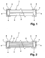
- the optical fiber 1 shown in Fig. 1 has a hollow fiber core 2 and an outer fiber jacket 3 for guiding the coupled into the fiber core 2 light.
- the hollow fiber core 2 is frontally open at both fiber ends 4 , wherein each fiber end 4 is dust-tight surrounded by a cap-shaped protective element 5 , which frontally before the fiber end 4 has a flat window 6 for coupling and decoupling of the hollow fiber core 2 to leading light ,
- the protective element 5 consists of ausgasungslockm material (eg metal or glass) and seals the fiber end 4 from air or gas tight.
- the window 6 is uncoated on one or both sides and spaced from the fiber end 4 in the mm to cm range, so that a sealed gap 7 remains between the fiber end 4 and the window 6.
Landscapes
- Physics & Mathematics (AREA)
- General Physics & Mathematics (AREA)
- Optics & Photonics (AREA)
- Optical Fibers, Optical Fiber Cores, And Optical Fiber Bundles (AREA)
- Optical Couplings Of Light Guides (AREA)
- Light Guides In General And Applications Therefor (AREA)
Abstract
Description
- Die vorliegende Erfindung betrifft eine optische Faser mit hohlem Faserkern.
- Eine Hohlfaser (hollow core fiber) hat einen hohlen Faserkem, durch den Licht geführt wird. Dadurch entfallen die Fresnellreflexionen an den Faserenden, und nichtlineare Effekte im Glaskern, wie sie bei herkömmlichen Fasern auftreten, sind stark reduziert. Um die Lichtführung im Faserkem aufrecht zu erhalten, ist der hohle Faserkem in der Regel von weiteren hohlen Bereichen umgeben, deren Durchmesser meist unter dem Durchmesser des Faserkems liegen.
- Der zumeist sehr dünne hohle Faserkern mit einem Durchmesser von einigen µm bis einigen 100 µm ist anfällig gegen Verschmutzungen, insbesondere gegen Wasser, das durch Kapillarwirkung in die Faser gezogen wird und ihre Funktion stört oder ganz unterbindet. Zum Schutz der hohlen Bereiche wird an Fasern mit hohlen Bereichen in der Regel ein Teilstück ohne Hohlräume angespleisst, oder das Endstück der Faser wird kollabiert. In beiden Fällen geht der Vorteil der fehlenden Fresnellreflexionen an den Faserendflächen verloren. Eventuell kann auch die Einkopplung von Strahlung in den Faserkem stark gestört sein.
- Demgegenüber ist es die Aufgabe der vorliegenden Erfindung, eine optische Faser der eingangs genannten Art mit einem anderen Schutz für die Hohlräume auszubilden.
- Diese Aufgabe wird erfindungsgemäß dadurch gelöst, dass der hohle Faserkem an beiden Faserenden stirnseitig offen ist und jedes Faserende von einem Schutzelement staubdicht umgeben ist, welches stirnseitig vor dem Faserende ein Fenster zur Ein- und Auskopplung des durch den hohlen Faserkem zu führenden Lichts aufweist. Bevorzugt ist der Faserkem zur Führung des darin eingekoppelten Lichts von einem Fasermantel umgeben, welcher stirnseitig offene Hohlräume aufweist. Der Abstand zwischen dem Faserende und dem Fenster des Schutzelements liegt vorzugsweise im mm- bis cm-Bereich.
- Erfindungsgemäß sind der hohle Faserkem und, falls vorhanden, auch Hohlräume des Fasermantels am Faserende offen gelassen und die beiden Faserenden jeweils mithilfe des Schutzelements abgedichtet. Das Schutzelement muss das Faserende in jedem Fall staubdicht abdichten, da Staubteilchen, die sich im Strahlungskegel nahe dem Faserende aufhalten, in Richtung der stärkeren Strahlungsfeldstärke und daher in den hohlen Faserkern hineingezogen werden können.
- Um störende Fresnellreflexionen am Fenster des Schutzelements zu verhindern, ist das Fenster vorzugsweise beidseitig entspiegelt. Die Entspiegelung sollte für alle zu übertragenden Wellenlängen geeignet sein (z.B. für einen "Arbeitslaser" bei 1064 nm und einen "Pilotlaser" bei 630 nm).
- Vorteilhaft dichtet das Schutzelement das Faserende wasserdicht ab, um eine mögliche Betauung der Faser zu verhindern. Wenn Wasser auf die Faserendfläche gelangt, wird es sofort durch Kapillarwirkung in den hohlen Faserkern und die Hohlräume gezogen. Dies beeinträchtigt oder unterbindet die Funktion der Faser als Lichtleiter.
- Besonders vorteilhaft dichtet das Schutzelement das Faserende luft- bzw. gasdicht ab, so dass die optische Faser dauerhaft mit speziellen Gasen gefüllt werden kann, um ihre Eigenschaften zu verändern. Beispielsweise kann Helium zur besseren Wärmeleitung oder SF6 zur Erzielung einer höheren Feldstärke in der optischen Faser eingesetzt werden.
- Alternativ ist eine Spülung der optischen Faser mit einem trockenen Gas sinnvoll, so dass mögliche Feuchtereste getrocknet werden. Eine Spülung mit Helium kann die Wärmeabfuhr aus dem Kembereich der Faser deutlich verbessern. Das kann beim Einsatz von PCF-Fasern (= photonic crystal fiber) für Faserlaser Vorteile bringen. Wird eine Gasspülung verwendet, so weist vorteilhaft das Schutzelement einen Gaseinlass bzw. -auslass in Form einer Gehäuseöffnung auf, die in einen Zwischenraum zwischen Faserende und Fenster mündet. Dabei ist vorteilhaft die als Gasauslass verwendete Gehäuseöffnung mit einem keramischen Feinstfilter abgedeckt.
- Bei der Ausführung des Schutzelementes sind keine Materialien zu verwenden, die ausgasen können, wie z.B. Kunststoffmaterialien mit Weichmachern, da sich die Ausgasprodukte im hohlen Faserkem der optischen Faser absetzen und das Lichtleitverhalten stören können.
- Weitere Vorteile und vorteilhafte Ausgestaltungen des Gegenstands der Erfindung sind der Beschreibung, der Zeichnung und den Ansprüchen entnehmbar. Ebenso können die vorstehend genannten und die noch weiter aufgeführten Merkmale je für sich oder zu mehreren in beliebigen Kombinationen Verwendung finden. Die gezeigten und beschriebenen Ausführungsformen sind nicht als abschließende Aufzählung zu verstehen, sondern haben vielmehr beispielhaften Charakter für die Schilderung der Erfindung.
- Es zeigt:
- Fig. 1
- eine erste Ausführungsform der erfindungsgemäßen optischen Faser im Längsschnitt; und
- Fig. 2
- eine zweite Ausführungsform der erfindungsgemäßen optischen Faser im Längsschnitt.
- Die in Fig. 1 gezeigte optische Faser 1 hat einen hohlen Faserkem 2 und einen äußeren Fasermantel 3 zur Führung des in den Faserkern 2 eingekoppelten Lichts. Der hohle Faserkern 2 ist an beiden Faserenden 4 stirnseitig offen, wobei jedes Faserende 4 von einem kappenförmigen Schutzelement 5 staubdicht umgeben ist, welches stirnseitig vor dem Faserende 4 ein ebenes Fenster 6 zur Ein- und Auskopplung des durch den hohlen Faserkem 2 zu führenden Lichts aufweist. Das Schutzelement 5 besteht aus ausgasungsfreiem Material (z.B. aus Metall oder Glas) und dichtet das Faserende 4 luft- bzw. gasdicht ab. Das Fenster 6 ist ein- oder beidseitig entspiegelt und vom Faserende 4 im mm- bis cm-Bereich beabstandet, so dass zwischen Faserende 4 und Fenster 6 ein abgedichteter Zwischenraum 7 verbleibt. Das Fenster 6 besteht vorzugsweise aus Quarzglas. Zum Spülen des hohlen Faserkems 2 mit einem Spülgas weist jedes Schutzelement 5 einen Gaseinlass bzw. -auslass in Form einer Gehäuseöffnung 8 auf, die in den Zwischenraum 7 mündet. Bevorzugt ist die als Gasauslass verwendete Gehäuseöffnung 8 mit einem keramischen Feinstfilter (nicht gezeigt) abgedeckt.
- Von der optischen Faser 1 unterscheidet sich die in Fig. 2 gezeigte optische Faser 1' allein dadurch, dass der Fasermantel 3 zur Führung des in den Faserkem 2 eingekoppelten Lichts Hohlräume 9 aufweist. Die im Bereich der Faserenden 4 befindlichen Hohlräume 9 sind stirnseitig offen und münden somit - wie auch der hohle Faserkem 2 - in den Zwischenraum 7.
Claims (10)
- Optische Faser (1; 1') mit hohlem Faserkem (2),
dadurch gekennzeichnet,
dass der hohle Faserkern (2) an beiden Faserenden (4) stirnseitig offen ist und jedes Faserende (4) von einem Schutzelement (5) staubdicht umgeben ist, welches stirnseitig vor dem Faserende (4) ein Fenster (6) zur Ein- und Auskopplung des durch den hohlen Faserkem (2) zu führenden Lichts aufweist. - Optische Faser nach Anspruch 1, dadurch gekennzeichnet, dass der Faserkem (2) zur Führung des darin eingekoppelten Lichts von einem Fasermantel (3) umgeben ist, welcher stirnseitig offene Hohlräume (9) aufweist.
- Optische Faser nach Anspruch 1 oder 2, dadurch gekennzeichnet, dass das Fenster (6) des Schutzelements (5) ein- oder beidseitig entspiegelt ist.
- Optische Faser nach einem der vorhergehenden Ansprüche, dadurch gekennzeichnet, dass das Fenster (6) des Schutzelements (5) eben ist.
- Optische Faser nach einem der vorhergehenden Ansprüche, dadurch gekennzeichnet, dass das Schutzelement (5) das Faserende (4) wasserdicht abdichtet.
- Optische Faser nach einem der vorhergehenden Ansprüche, dadurch gekennzeichnet, dass das Schutzelement (5) das Faserende (4) luft- bzw. gasdicht abdichtet.
- Optische Faser nach einem der vorhergehenden Ansprüche, dadurch gekennzeichnet, dass der hohle Faserkem (2) und, falls vorhanden, die stirnseitig offenen Hohlräume (9) des Fasermantels (3) mit Gas gefüllt sind.
- Optische Faser nach einem der vorhergehenden Ansprüche, dadurch gekennzeichnet, dass das Schutzelement (5) eine Gehäuseöffnung (8) aufweist, die in einen Zwischenraum (7) zwischen Faserende (4) und Fenster (6) mündet.
- Optische Faser nach einem der vorhergehenden Ansprüche, dadurch gekennzeichnet, dass das Schutzelement (5) aus ausgasungsfreiem Material besteht.
- Optische Faser nach einem der vorhergehenden Ansprüche, dadurch gekennzeichnet, dass der Abstand zwischen Faserende (4) und Fenster (6) im mm- bis cm-Bereich liegt.
Applications Claiming Priority (1)
| Application Number | Priority Date | Filing Date | Title |
|---|---|---|---|
| DE202005015728U DE202005015728U1 (de) | 2005-10-07 | 2005-10-07 | Optische Faser |
Publications (2)
| Publication Number | Publication Date |
|---|---|
| EP1772758A1 true EP1772758A1 (de) | 2007-04-11 |
| EP1772758B1 EP1772758B1 (de) | 2017-03-15 |
Family
ID=35669023
Family Applications (1)
| Application Number | Title | Priority Date | Filing Date |
|---|---|---|---|
| EP06020821.2A Active EP1772758B1 (de) | 2005-10-07 | 2006-10-04 | Optische Faser mit hohlem Faserkern |
Country Status (4)
| Country | Link |
|---|---|
| US (1) | US7373062B2 (de) |
| EP (1) | EP1772758B1 (de) |
| DE (1) | DE202005015728U1 (de) |
| DK (1) | DK1772758T3 (de) |
Cited By (3)
| Publication number | Priority date | Publication date | Assignee | Title |
|---|---|---|---|---|
| WO2016181100A1 (en) * | 2015-05-12 | 2016-11-17 | Cranfield University | Hollow fibre waveguide gas cells |
| FR3039289A1 (fr) * | 2015-07-22 | 2017-01-27 | Thales Sa | Terminaison pour fibre optique a coeur creux |
| DE102017114002A1 (de) | 2017-06-23 | 2018-12-27 | Trumpf Laser Gmbh | Lichtleitfasereinheit mit Faserendkappe und Verfahren zur Herstellung einer Lichtleitfasereinheit |
Families Citing this family (21)
| Publication number | Priority date | Publication date | Assignee | Title |
|---|---|---|---|---|
| DE102006030799B4 (de) * | 2006-06-30 | 2010-06-17 | Trumpf Laser- Und Systemtechnik Gmbh | Gaslaser mit einem instabilen Laserresonator und einer Lichtleiterfaser |
| JP2009175504A (ja) * | 2008-01-25 | 2009-08-06 | Fujifilm Corp | 光ファイバ構造体 |
| EP2058682B1 (de) * | 2008-03-13 | 2017-09-06 | Agilent Technologies, Inc. | Lichtleiterflüssigkeitsrohr mit Innen- und Außenkapillaren |
| US8123400B2 (en) * | 2008-04-16 | 2012-02-28 | Ofs Fitel, Llc | Multi-core fiber grating sensor |
| CN103189768B (zh) | 2010-11-03 | 2016-08-24 | 英派尔科技开发有限公司 | 光波导的形成 |
| WO2014159450A1 (en) | 2013-03-11 | 2014-10-02 | The Regents Of The University Of California | Hollow plastic waveguide for data center communications |
| DE102013213564A1 (de) | 2013-07-11 | 2015-01-15 | Carl Zeiss Smt Gmbh | Optische Hohlwellenleiter-Baugruppe |
| US9597749B2 (en) | 2015-05-26 | 2017-03-21 | Siemens Energy, Inc. | Laser waveguide with coaxial filler wire feed |
| CN108473356B (zh) | 2015-11-10 | 2022-05-17 | Nkt光子学有限公司 | 用于预制件的元件、纤维生产方法和由预制件拉制的光纤 |
| SG11201804738SA (en) | 2015-12-23 | 2018-07-30 | Nkt Photonics As | Hollow core optical fiber and a laser system |
| KR102677212B1 (ko) | 2015-12-23 | 2024-06-24 | 엔케이티 포토닉스 에이/에스 | 광결정 섬유 조립체 |
| EP3448818B1 (de) | 2016-04-27 | 2024-09-25 | NKT Photonics A/S | Verfahren zur faserherstellung |
| US11543685B2 (en) * | 2017-03-07 | 2023-01-03 | David T. Markus | Method and apparatus for image spacing |
| US10484120B2 (en) * | 2017-09-30 | 2019-11-19 | Intel Corporation | Waveguide couplers and junctions to enable frequency division multiplexed sensor systems in autonomous vehicle |
| KR102719351B1 (ko) | 2019-08-29 | 2024-10-21 | 에이에스엠엘 네델란즈 비.브이. | 광원에 대한 단부 패싯 보호 및 계측 응용들에서 사용하기 위한 방법 |
| CN114585953A (zh) | 2019-10-24 | 2022-06-03 | Asml荷兰有限公司 | 用于宽带辐射生成的基于空芯光子晶体光纤的光学部件 |
| US12535640B2 (en) | 2020-08-25 | 2026-01-27 | Hakusan Inc. | Optical fiber termination structure, optical connection component and hollow-core optical fiber |
| US11446776B2 (en) * | 2020-08-27 | 2022-09-20 | Northrop Grumman Systems Corporation | Method for assembling a hollow core optical fiber array launcher |
| CN114865430B (zh) * | 2022-03-04 | 2025-07-08 | 中国科学院上海光学精密机械研究所 | 大功率激光空芯光纤气体填充耦合端子 |
| DE102022120269A1 (de) | 2022-08-11 | 2024-02-22 | Valeo Schalter Und Sensoren Gmbh | Fahrzeugkommunikationssystem für ein Fahrzeug |
| DE102024207074A1 (de) * | 2024-07-26 | 2026-01-29 | Carl Zeiss Smt Gmbh | Optische Hohlwellenleiter-Baugruppe, Beleuchtungsoptik und Inspektionsanlage |
Citations (5)
| Publication number | Priority date | Publication date | Assignee | Title |
|---|---|---|---|---|
| GB1461400A (en) * | 1973-06-06 | 1977-01-13 | Secr Defence | Connectors for liquid-core optical fibres |
| GB2110834A (en) * | 1981-12-01 | 1983-06-22 | Coal Ind | Connectors for optical fibres |
| JPS6169005A (ja) * | 1985-09-10 | 1986-04-09 | Fujikura Ltd | 赤外用光フアイバの端末の固定構造 |
| EP1255137A2 (de) * | 2001-04-25 | 2002-11-06 | Sumitomo Electric Industries, Ltd. | Optische Faser und Herstellungsverfahren |
| US20040258381A1 (en) * | 2003-05-28 | 2004-12-23 | Borrelli Nicholas F. | Methods of generating and transporting short wavelength radiation and apparati used therein |
Family Cites Families (14)
| Publication number | Priority date | Publication date | Assignee | Title |
|---|---|---|---|---|
| US3961283A (en) * | 1975-03-14 | 1976-06-01 | Hughes Aircraft Company | Waveguide gas laser with wavelength selective guide |
| IL82163A (en) * | 1987-04-10 | 1990-07-26 | Laser Ind Ltd | Optical-fiber type power transmission device |
| JPH01309007A (ja) | 1988-06-08 | 1989-12-13 | Hitachi Cable Ltd | 大電力炭酸ガスレーザ光伝送装置 |
| US5325458A (en) * | 1992-02-07 | 1994-06-28 | Surgilase, Inc. | Monolithic hollow waveguide and method and apparatus for making the same |
| DE4212392A1 (de) | 1992-04-13 | 1993-10-14 | Baasel Carl Lasertech | Lichtleiter mit flüssigem Kern |
| ZA948392B (en) | 1993-10-29 | 1995-06-26 | Harold Frederick Eastgate | Liquid core optical waveguid |
| US5434942A (en) * | 1993-11-24 | 1995-07-18 | The State Of Israel, Atomic Energy Commission, Soreq Nuclear Research Center | Low threshold Brillouin active devices |
| US5734765A (en) * | 1994-07-26 | 1998-03-31 | Ceramoptec Industries Inc. | Damage resistant infrared fiber delivery device and system |
| JP3535685B2 (ja) * | 1997-02-07 | 2004-06-07 | 光信 宮城 | 医療用レーザプローブ |
| US20050195392A1 (en) * | 2001-01-29 | 2005-09-08 | Horiba, Ltd. | Fluid analyzer |
| JP3762677B2 (ja) | 2001-01-29 | 2006-04-05 | 株式会社 堀場アドバンスドテクノ | 流体分析用セルおよびこれを用いた分析装置 |
| US7295739B2 (en) * | 2004-10-20 | 2007-11-13 | Kla-Tencor Technologies Corporation | Coherent DUV illumination for semiconductor wafer inspection |
| US7574076B2 (en) * | 2005-04-08 | 2009-08-11 | Arryx, Inc. | Apparatus for optically-based sorting within liquid core waveguides |
| US7283712B2 (en) * | 2005-05-03 | 2007-10-16 | United States Of America As Represented By The Secretary Of The Navy | Gas filled hollow core chalcogenide photonic bandgap fiber Raman device and method |
-
2005
- 2005-10-07 DE DE202005015728U patent/DE202005015728U1/de not_active Expired - Lifetime
-
2006
- 2006-10-04 EP EP06020821.2A patent/EP1772758B1/de active Active
- 2006-10-04 DK DK06020821.2T patent/DK1772758T3/en active
- 2006-10-10 US US11/548,127 patent/US7373062B2/en active Active
Patent Citations (5)
| Publication number | Priority date | Publication date | Assignee | Title |
|---|---|---|---|---|
| GB1461400A (en) * | 1973-06-06 | 1977-01-13 | Secr Defence | Connectors for liquid-core optical fibres |
| GB2110834A (en) * | 1981-12-01 | 1983-06-22 | Coal Ind | Connectors for optical fibres |
| JPS6169005A (ja) * | 1985-09-10 | 1986-04-09 | Fujikura Ltd | 赤外用光フアイバの端末の固定構造 |
| EP1255137A2 (de) * | 2001-04-25 | 2002-11-06 | Sumitomo Electric Industries, Ltd. | Optische Faser und Herstellungsverfahren |
| US20040258381A1 (en) * | 2003-05-28 | 2004-12-23 | Borrelli Nicholas F. | Methods of generating and transporting short wavelength radiation and apparati used therein |
Cited By (5)
| Publication number | Priority date | Publication date | Assignee | Title |
|---|---|---|---|---|
| WO2016181100A1 (en) * | 2015-05-12 | 2016-11-17 | Cranfield University | Hollow fibre waveguide gas cells |
| FR3039289A1 (fr) * | 2015-07-22 | 2017-01-27 | Thales Sa | Terminaison pour fibre optique a coeur creux |
| DE102017114002A1 (de) | 2017-06-23 | 2018-12-27 | Trumpf Laser Gmbh | Lichtleitfasereinheit mit Faserendkappe und Verfahren zur Herstellung einer Lichtleitfasereinheit |
| WO2018234081A1 (de) | 2017-06-23 | 2018-12-27 | Trumpf Laser Gmbh | Lichtleitfasereinheit mit faserendkappe und verfahren zur herstellung einer lichtleitfasereinheit |
| DE102017114002B4 (de) | 2017-06-23 | 2023-05-11 | Trumpf Laser Gmbh | Lichtleitfasereinheit mit Faserendkappe und Verfahren zur Herstellung einer Lichtleitfasereinheit |
Also Published As
| Publication number | Publication date |
|---|---|
| US7373062B2 (en) | 2008-05-13 |
| EP1772758B1 (de) | 2017-03-15 |
| US20070165991A1 (en) | 2007-07-19 |
| DE202005015728U1 (de) | 2006-01-12 |
| DK1772758T3 (en) | 2017-07-03 |
Similar Documents
| Publication | Publication Date | Title |
|---|---|---|
| EP1772758B1 (de) | Optische Faser mit hohlem Faserkern | |
| DE102011085637B4 (de) | Optische Transportfaser und Verfahren zu deren Herstellung und Verfahren zum Verkleben | |
| EP0151743B1 (de) | Optisches Übertragungselement | |
| DE69800563T2 (de) | Optische Faser auf Quartzbasis mit einem zwischenliegenden Mantel mit niederem Brechungsindex | |
| DE69410335T2 (de) | Optische Faser | |
| EP2461194B1 (de) | Spleißverbindung zwischen zwei optischen Fasern sowie Verfahren zum Herstellen einer solchen Spleißverbindung | |
| EP3407772B1 (de) | Beleuchtungseinrichtung | |
| EP1770417B1 (de) | Optische Faser und Verfahren zu ihrer Herstellung | |
| DE102008044938A1 (de) | Verfahren zur Terminierung von lichtleitenden Faserbündeln | |
| DE1494872B2 (de) | Verfahren zum herstellen von lichtleitenden systemen | |
| DE112017004440T5 (de) | Optische Verbindungsstruktur und optisches Modul | |
| DE102011087854B4 (de) | Lichtleiter mit einer Lichtleitfaser und einem Modenstripper | |
| EP1186929B2 (de) | Anordnung zum Untersuchen mikroskopischer Präparate mit einem Scanmikroskop | |
| DE3689016T2 (de) | Optische Faser mit Plastikhülle. | |
| DE2907650C3 (de) | Multimode-Lichtleiter | |
| DE102022102057B4 (de) | Lichtwellenleiterstecker sowie Lichtwellenleiterverbinder mit einem solchen | |
| EP2380052B1 (de) | Spleissverbindung zwischen zwei optischen fasern sowie verfahren zum herstellen einer solchen spleissverbindung | |
| DE102023118609B4 (de) | Multilichtwellenleiterstecker sowie Lichtwellenleiterverbinder mit einem solchen | |
| WO2008022959A1 (de) | Lichtwellenleiter | |
| EP0136365A1 (de) | Endoskopisches Sehrohr | |
| EP0557587A1 (de) | Bauteil für die Übertragung von energiereichem Licht und Verwendung des Bauteils | |
| DE1772354B1 (de) | Lichtleitfaser,die gegebenenfalls entstehendes Streulicht absorbiert,und Verfahren zu ihrer Herstellung | |
| EP0538879A1 (de) | Wellenlängenfilter für Lichtwellenleiter | |
| DE19517952A1 (de) | Optischer Verstärker mit Praseodym-dotierter optischer Faser | |
| EP0043450A1 (de) | Filterelement für die optische Nachrichtentechnik |
Legal Events
| Date | Code | Title | Description |
|---|---|---|---|
| PUAI | Public reference made under article 153(3) epc to a published international application that has entered the european phase |
Free format text: ORIGINAL CODE: 0009012 |
|
| AK | Designated contracting states |
Kind code of ref document: A1 Designated state(s): AT BE BG CH CY CZ DE DK EE ES FI FR GB GR HU IE IS IT LI LT LU LV MC NL PL PT RO SE SI SK TR |
|
| AX | Request for extension of the european patent |
Extension state: AL BA HR MK YU |
|
| 17P | Request for examination filed |
Effective date: 20070327 |
|
| 17Q | First examination report despatched |
Effective date: 20070612 |
|
| AKX | Designation fees paid |
Designated state(s): AT BE BG CH CY CZ DE DK EE ES FI FR GB GR HU IE IS IT LI LT LU LV MC NL PL PT RO SE SI SK TR |
|
| RAP1 | Party data changed (applicant data changed or rights of an application transferred) |
Owner name: TRUMPF LASER GMBH |
|
| RAP1 | Party data changed (applicant data changed or rights of an application transferred) |
Owner name: TRUMPF LASER GMBH |
|
| GRAP | Despatch of communication of intention to grant a patent |
Free format text: ORIGINAL CODE: EPIDOSNIGR1 |
|
| INTG | Intention to grant announced |
Effective date: 20161020 |
|
| GRAS | Grant fee paid |
Free format text: ORIGINAL CODE: EPIDOSNIGR3 |
|
| GRAA | (expected) grant |
Free format text: ORIGINAL CODE: 0009210 |
|
| AK | Designated contracting states |
Kind code of ref document: B1 Designated state(s): AT BE BG CH CY CZ DE DK EE ES FI FR GB GR HU IE IS IT LI LT LU LV MC NL PL PT RO SE SI SK TR |
|
| REG | Reference to a national code |
Ref country code: CH Ref legal event code: EP Ref country code: GB Ref legal event code: FG4D Free format text: NOT ENGLISH |
|
| REG | Reference to a national code |
Ref country code: IE Ref legal event code: FG4D Free format text: LANGUAGE OF EP DOCUMENT: GERMAN |
|
| REG | Reference to a national code |
Ref country code: AT Ref legal event code: REF Ref document number: 876150 Country of ref document: AT Kind code of ref document: T Effective date: 20170415 |
|
| REG | Reference to a national code |
Ref country code: DE Ref legal event code: R096 Ref document number: 502006015410 Country of ref document: DE |
|
| REG | Reference to a national code |
Ref country code: SE Ref legal event code: TRGR |
|
| REG | Reference to a national code |
Ref country code: DK Ref legal event code: T3 Effective date: 20170627 |
|
| REG | Reference to a national code |
Ref country code: NL Ref legal event code: MP Effective date: 20170315 |
|
| REG | Reference to a national code |
Ref country code: LT Ref legal event code: MG4D |
|
| PG25 | Lapsed in a contracting state [announced via postgrant information from national office to epo] |
Ref country code: FI Free format text: LAPSE BECAUSE OF FAILURE TO SUBMIT A TRANSLATION OF THE DESCRIPTION OR TO PAY THE FEE WITHIN THE PRESCRIBED TIME-LIMIT Effective date: 20170315 Ref country code: LT Free format text: LAPSE BECAUSE OF FAILURE TO SUBMIT A TRANSLATION OF THE DESCRIPTION OR TO PAY THE FEE WITHIN THE PRESCRIBED TIME-LIMIT Effective date: 20170315 Ref country code: GR Free format text: LAPSE BECAUSE OF FAILURE TO SUBMIT A TRANSLATION OF THE DESCRIPTION OR TO PAY THE FEE WITHIN THE PRESCRIBED TIME-LIMIT Effective date: 20170616 |
|
| PG25 | Lapsed in a contracting state [announced via postgrant information from national office to epo] |
Ref country code: LV Free format text: LAPSE BECAUSE OF FAILURE TO SUBMIT A TRANSLATION OF THE DESCRIPTION OR TO PAY THE FEE WITHIN THE PRESCRIBED TIME-LIMIT Effective date: 20170315 Ref country code: BG Free format text: LAPSE BECAUSE OF FAILURE TO SUBMIT A TRANSLATION OF THE DESCRIPTION OR TO PAY THE FEE WITHIN THE PRESCRIBED TIME-LIMIT Effective date: 20170615 |
|
| PG25 | Lapsed in a contracting state [announced via postgrant information from national office to epo] |
Ref country code: NL Free format text: LAPSE BECAUSE OF FAILURE TO SUBMIT A TRANSLATION OF THE DESCRIPTION OR TO PAY THE FEE WITHIN THE PRESCRIBED TIME-LIMIT Effective date: 20170315 |
|
| REG | Reference to a national code |
Ref country code: FR Ref legal event code: PLFP Year of fee payment: 12 |
|
| PG25 | Lapsed in a contracting state [announced via postgrant information from national office to epo] |
Ref country code: SK Free format text: LAPSE BECAUSE OF FAILURE TO SUBMIT A TRANSLATION OF THE DESCRIPTION OR TO PAY THE FEE WITHIN THE PRESCRIBED TIME-LIMIT Effective date: 20170315 Ref country code: EE Free format text: LAPSE BECAUSE OF FAILURE TO SUBMIT A TRANSLATION OF THE DESCRIPTION OR TO PAY THE FEE WITHIN THE PRESCRIBED TIME-LIMIT Effective date: 20170315 Ref country code: CZ Free format text: LAPSE BECAUSE OF FAILURE TO SUBMIT A TRANSLATION OF THE DESCRIPTION OR TO PAY THE FEE WITHIN THE PRESCRIBED TIME-LIMIT Effective date: 20170315 Ref country code: RO Free format text: LAPSE BECAUSE OF FAILURE TO SUBMIT A TRANSLATION OF THE DESCRIPTION OR TO PAY THE FEE WITHIN THE PRESCRIBED TIME-LIMIT Effective date: 20170315 Ref country code: ES Free format text: LAPSE BECAUSE OF FAILURE TO SUBMIT A TRANSLATION OF THE DESCRIPTION OR TO PAY THE FEE WITHIN THE PRESCRIBED TIME-LIMIT Effective date: 20170315 |
|
| PG25 | Lapsed in a contracting state [announced via postgrant information from national office to epo] |
Ref country code: IS Free format text: LAPSE BECAUSE OF FAILURE TO SUBMIT A TRANSLATION OF THE DESCRIPTION OR TO PAY THE FEE WITHIN THE PRESCRIBED TIME-LIMIT Effective date: 20170715 Ref country code: PT Free format text: LAPSE BECAUSE OF FAILURE TO SUBMIT A TRANSLATION OF THE DESCRIPTION OR TO PAY THE FEE WITHIN THE PRESCRIBED TIME-LIMIT Effective date: 20170717 Ref country code: PL Free format text: LAPSE BECAUSE OF FAILURE TO SUBMIT A TRANSLATION OF THE DESCRIPTION OR TO PAY THE FEE WITHIN THE PRESCRIBED TIME-LIMIT Effective date: 20170315 |
|
| REG | Reference to a national code |
Ref country code: DE Ref legal event code: R097 Ref document number: 502006015410 Country of ref document: DE |
|
| PLBE | No opposition filed within time limit |
Free format text: ORIGINAL CODE: 0009261 |
|
| STAA | Information on the status of an ep patent application or granted ep patent |
Free format text: STATUS: NO OPPOSITION FILED WITHIN TIME LIMIT |
|
| 26N | No opposition filed |
Effective date: 20171218 |
|
| PG25 | Lapsed in a contracting state [announced via postgrant information from national office to epo] |
Ref country code: SI Free format text: LAPSE BECAUSE OF FAILURE TO SUBMIT A TRANSLATION OF THE DESCRIPTION OR TO PAY THE FEE WITHIN THE PRESCRIBED TIME-LIMIT Effective date: 20170315 |
|
| PG25 | Lapsed in a contracting state [announced via postgrant information from national office to epo] |
Ref country code: MC Free format text: LAPSE BECAUSE OF FAILURE TO SUBMIT A TRANSLATION OF THE DESCRIPTION OR TO PAY THE FEE WITHIN THE PRESCRIBED TIME-LIMIT Effective date: 20170315 |
|
| REG | Reference to a national code |
Ref country code: CH Ref legal event code: PL |
|
| REG | Reference to a national code |
Ref country code: IE Ref legal event code: MM4A |
|
| PG25 | Lapsed in a contracting state [announced via postgrant information from national office to epo] |
Ref country code: LU Free format text: LAPSE BECAUSE OF NON-PAYMENT OF DUE FEES Effective date: 20171004 Ref country code: CH Free format text: LAPSE BECAUSE OF NON-PAYMENT OF DUE FEES Effective date: 20171031 Ref country code: LI Free format text: LAPSE BECAUSE OF NON-PAYMENT OF DUE FEES Effective date: 20171031 |
|
| REG | Reference to a national code |
Ref country code: BE Ref legal event code: MM Effective date: 20171031 |
|
| PG25 | Lapsed in a contracting state [announced via postgrant information from national office to epo] |
Ref country code: BE Free format text: LAPSE BECAUSE OF NON-PAYMENT OF DUE FEES Effective date: 20171031 |
|
| REG | Reference to a national code |
Ref country code: FR Ref legal event code: PLFP Year of fee payment: 13 |
|
| PG25 | Lapsed in a contracting state [announced via postgrant information from national office to epo] |
Ref country code: IE Free format text: LAPSE BECAUSE OF NON-PAYMENT OF DUE FEES Effective date: 20171004 |
|
| REG | Reference to a national code |
Ref country code: AT Ref legal event code: MM01 Ref document number: 876150 Country of ref document: AT Kind code of ref document: T Effective date: 20171004 |
|
| PG25 | Lapsed in a contracting state [announced via postgrant information from national office to epo] |
Ref country code: AT Free format text: LAPSE BECAUSE OF NON-PAYMENT OF DUE FEES Effective date: 20171004 |
|
| PG25 | Lapsed in a contracting state [announced via postgrant information from national office to epo] |
Ref country code: HU Free format text: LAPSE BECAUSE OF FAILURE TO SUBMIT A TRANSLATION OF THE DESCRIPTION OR TO PAY THE FEE WITHIN THE PRESCRIBED TIME-LIMIT; INVALID AB INITIO Effective date: 20061004 |
|
| PG25 | Lapsed in a contracting state [announced via postgrant information from national office to epo] |
Ref country code: CY Free format text: LAPSE BECAUSE OF NON-PAYMENT OF DUE FEES Effective date: 20170315 |
|
| PG25 | Lapsed in a contracting state [announced via postgrant information from national office to epo] |
Ref country code: TR Free format text: LAPSE BECAUSE OF FAILURE TO SUBMIT A TRANSLATION OF THE DESCRIPTION OR TO PAY THE FEE WITHIN THE PRESCRIBED TIME-LIMIT Effective date: 20170315 |
|
| PGFP | Annual fee paid to national office [announced via postgrant information from national office to epo] |
Ref country code: SE Payment date: 20211020 Year of fee payment: 16 |
|
| PGFP | Annual fee paid to national office [announced via postgrant information from national office to epo] |
Ref country code: IT Payment date: 20211028 Year of fee payment: 16 |
|
| REG | Reference to a national code |
Ref country code: SE Ref legal event code: EUG |
|
| PG25 | Lapsed in a contracting state [announced via postgrant information from national office to epo] |
Ref country code: SE Free format text: LAPSE BECAUSE OF NON-PAYMENT OF DUE FEES Effective date: 20221005 |
|
| PG25 | Lapsed in a contracting state [announced via postgrant information from national office to epo] |
Ref country code: IT Free format text: LAPSE BECAUSE OF NON-PAYMENT OF DUE FEES Effective date: 20221004 |
|
| REG | Reference to a national code |
Ref country code: DE Ref legal event code: R082 Ref document number: 502006015410 Country of ref document: DE Representative=s name: PROBST, MATTHIAS, DE Ref country code: DE Ref legal event code: R081 Ref document number: 502006015410 Country of ref document: DE Owner name: TRUMPF LASER SE, DE Free format text: FORMER OWNER: TRUMPF LASER GMBH, 78713 SCHRAMBERG, DE |
|
| PGFP | Annual fee paid to national office [announced via postgrant information from national office to epo] |
Ref country code: DE Payment date: 20241021 Year of fee payment: 19 |
|
| PGFP | Annual fee paid to national office [announced via postgrant information from national office to epo] |
Ref country code: DK Payment date: 20241025 Year of fee payment: 19 |
|
| PGFP | Annual fee paid to national office [announced via postgrant information from national office to epo] |
Ref country code: GB Payment date: 20241022 Year of fee payment: 19 |
|
| PGFP | Annual fee paid to national office [announced via postgrant information from national office to epo] |
Ref country code: FR Payment date: 20241021 Year of fee payment: 19 |