EP1772312A1 - Fahrtrichtungsanzeiger für Kraftfahrzeuge - Google Patents
Fahrtrichtungsanzeiger für Kraftfahrzeuge Download PDFInfo
- Publication number
- EP1772312A1 EP1772312A1 EP05360040A EP05360040A EP1772312A1 EP 1772312 A1 EP1772312 A1 EP 1772312A1 EP 05360040 A EP05360040 A EP 05360040A EP 05360040 A EP05360040 A EP 05360040A EP 1772312 A1 EP1772312 A1 EP 1772312A1
- Authority
- EP
- European Patent Office
- Prior art keywords
- lever
- movable finger
- movable
- support
- finger
- Prior art date
- Legal status (The legal status is an assumption and is not a legal conclusion. Google has not performed a legal analysis and makes no representation as to the accuracy of the status listed.)
- Granted
Links
Images


Classifications
-
- B—PERFORMING OPERATIONS; TRANSPORTING
- B60—VEHICLES IN GENERAL
- B60Q—ARRANGEMENT OF SIGNALLING OR LIGHTING DEVICES, THE MOUNTING OR SUPPORTING THEREOF OR CIRCUITS THEREFOR, FOR VEHICLES IN GENERAL
- B60Q1/00—Arrangement of optical signalling or lighting devices, the mounting or supporting thereof or circuits therefor
- B60Q1/26—Arrangement of optical signalling or lighting devices, the mounting or supporting thereof or circuits therefor the devices being primarily intended to indicate the vehicle, or parts thereof, or to give signals, to other traffic
- B60Q1/34—Arrangement of optical signalling or lighting devices, the mounting or supporting thereof or circuits therefor the devices being primarily intended to indicate the vehicle, or parts thereof, or to give signals, to other traffic for indicating change of drive direction
- B60Q1/40—Arrangement of optical signalling or lighting devices, the mounting or supporting thereof or circuits therefor the devices being primarily intended to indicate the vehicle, or parts thereof, or to give signals, to other traffic for indicating change of drive direction having mechanical, electric or electronic automatic return to inoperative position
- B60Q1/42—Arrangement of optical signalling or lighting devices, the mounting or supporting thereof or circuits therefor the devices being primarily intended to indicate the vehicle, or parts thereof, or to give signals, to other traffic for indicating change of drive direction having mechanical, electric or electronic automatic return to inoperative position having mechanical automatic return to inoperative position due to steering-wheel position, e.g. with roller wheel control
- B60Q1/425—Arrangement of optical signalling or lighting devices, the mounting or supporting thereof or circuits therefor the devices being primarily intended to indicate the vehicle, or parts thereof, or to give signals, to other traffic for indicating change of drive direction having mechanical, electric or electronic automatic return to inoperative position having mechanical automatic return to inoperative position due to steering-wheel position, e.g. with roller wheel control using a latching element for resetting a switching element
Definitions
- the present invention relates to the general technical field of indicators indicating the change of direction of vehicles. These luminous and / or audible type devices make it possible to warn other road users of the imminence of a maneuver or a change of direction of a vehicle.
- these devices are provided with an unlocking mechanism bringing the actuating lever of the devices into their rest position after their actuation by simply rotating the steering column in the opposite direction in the sense of initial actuation of the lever.
- an unlocking mechanism bringing the actuating lever of the devices into their rest position after their actuation by simply rotating the steering column in the opposite direction in the sense of initial actuation of the lever.
- the user holds the operating lever in one of its operating positions, with one of the indicators, for example of the left or right flashing type therefore active, while turning in the opposite direction. steering column. It is then essential to provide in the device safety means preventing deterioration or deformation of the unlocking mechanism or parts cooperating with the latter.
- the object of the present invention is to overcome the aforementioned drawbacks and in particular to improve their reliability.
- Another object of the invention is to reduce the number of parts used and to simplify their assembly. These measures, which reduce costs in manufacturing and assembly, have a very favorable economic impact.
- the invention finally aims to reduce the size of such indicator devices, which simplifies the management of the space at the top of the steering columns, a space that is increasingly encumbered by the multiplication of the functions provided. implemented in current cars.
- the elastic pusher which in fact makes the connection between the lever and the movable finger, has a sufficient stroke to absorb a displacement of support cams disposed at both ends of the movable indexing surface and pressing on the pusher when moving said movable indexing surface to bring the lever to the central position while the latter is locked in the lateral position.
- said elastic pusher is guided in the lever in axial sliding.
- the elastic pusher is a rigid support member connected to a spring integrated in the actuating lever.
- the elastic pusher moving on the fixed indexing surface, also makes it possible to generate a sensory feedback to the user manipulating the operating lever.
- the movable finger which makes the mechanical connection between the lever and the steering column, is guided in translation and pivoting by the fixed support. There is therefore only one moving part relative to the fixed support, outside the operating lever.
- the groove is shaped through in the fixed support.
- the groove preferably has a substantially T-shaped. This configuration is simple and easy to achieve.
- One of the innovative aspects, as a simplifier, of the invention consists of the double indexing surface and the possibility of cooperation between the two surfaces.
- the fixed indexing surface and the mobile indexing surface are located on a respective edge of the support and the mobile finger oriented orthogonally to the plane of their relative movements. These edges are superimposed so as to cooperate simultaneously or individually with the elastic pusher, according to the positioning of the movable finger and the actuating lever relative to the fixed support.
- the fixed indexing surface consists for example of three juxtaposed recesses of the same depth, which can accommodate the elastic pusher
- the movable indexing surface comprises three cavities, framed by the support cams, whose central cavity is deeper than the lateral cavities and is superimposed strictly on the central hollow of the fixed indexing surface at rest of the movable finger, positioning the lateral cavities protruding from the support.
- the lever When the lever takes one of the lateral positions, it pushes said lateral cavities so that their bottom is superimposed on that of the lateral recesses of the fixed indexing surface, leading to translational movement of the movable finger by sliding the pins in the first portion of the groove.
- the elastic member is a spring comprising a central portion housed in a groove and resting on a shoulder of the movable finger, and two elastic lateral portions fixed to the support in a position below its connection with the movable finger , so as to impart a curved configuration to the spring.
- Such a member ensures both the return in translation and in rotation, since it is able to exert decomposable restoring forces in a component parallel to the direction of translation of the movable finger and a component perpendicular thereto, in particular because of its configuration in an arc.
- the actuating lever is pivotally mounted on a plate secured to the fixed support. This improves the compactness of the device according to the invention.
- the device also comprises an actuating lever (3) mechanically connected to the fixed support (1) and movable between stable central, left and right positions, respectively. These positions correspond to a displacement, for example by pivoting of the operating lever (3) between a central position for which no direction change indicator is activated and active left and right lateral positions, for which a corresponding indicator is activated. for example to indicate a change of direction.
- the device according to the invention also comprises a movable finger (4) also called crossbow, in mechanical connection with the actuating lever (3).
- a free end (5) of the movable finger (4) cooperates with a driving member (2a) rotating with the steering column (2).
- the drive member (2a) has the function of returning the actuating lever (3) to its central position at from a left or right position in case of rotation of said drive member (2a) in opposite direction to the previous movement of the operating lever (3).
- the movable finger (4) moves in translation so that the free end (5) has a spacing (D a ) relative to the fixed support (1).
- the spacing (D a ) is for example 3 mm greater than a spacing (D i ) relative to the fixed support (1) corresponding to a central positioning of the operating lever (3), shown schematically in FIGS. 2.
- the steering column (2) and the driving member (2a) can rotate freely without abutting on the free end (5) of the movable finger (4).
- the device of the invention also comprises safety means guaranteeing the integrity of the device in case of forced holding of the operating lever (3) in a left or right position, during a rotation in the opposite direction of the organ drive (2a), to prevent its deterioration or that of its constituent elements.
- the movable finger (4) returns the operating lever (3) to its central position during a rotation in the direction R of the steering column (2) which corresponds to the opposite direction of that implied in principle the lateral position of the lever (3).
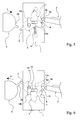
- FIG. 5 shows the absence of interaction between the movable finger (4) and the operating lever (3) when the steering column (2) rotates in the direction corresponding to the lateral position of the lever (3).
- the drive member (2a) turning in the indicated direction L, abuts against the free end (5) and rotates the movable finger (4) without affecting the position of the lever (3).
- FIG. 6 shows the displacement of the movable finger (4) during a forced holding of the operating lever (3), when the column (2) rotates in the opposite direction R.
- the movable finger (4) is slidably mounted and pivoted on the fixed support (1).
- An elastic member (6) allows to bring it back into its clutch position (see Figure 3) at the return of a left or right rotation following a rotation of the steering column (2) in the opposite direction of the rotation corresponding to the position side of the lever (3).
- the return of the lever (3) in the central position also triggers the return of the movable finger (4) to its initial disengaged position.
- the movable finger (4) has an indexing surface (7) on which moves an elastic pusher (3a) of the actuating lever (3).
- the indexing surface (7), movable with the finger (4), is associated with an indexing surface fixed (8) fixed support (1) on which also moves the elastic pusher (3a).
- the latter is mounted on the actuating lever (3) and can therefore move simultaneously on the two indexing surfaces (7) and (8) as a function of the displacements and the positions of the movable finger (4) and the lever. actuation (3).
- the fixed indexing surface (8) has a left recess (9a), a central recess (9b) and a right recess (9c) for defining discrete and stable positions respectively corresponding to the left, central and right positions of the lever. actuation (3).
- the movable indexing surface (7) has a left cavity (10a), a central cavity (10b) and a right cavity (10c) in which the elastic pusher (3a) is also housed, thus defining a stable positioning of the finger mobile (4) relative to the actuating lever (3) on the one hand and relative to the fixed support (1) on the other hand (see Figure 3).
- FIG. 5 shows the positioning of the elastic pusher (3a) in the left recess (9a) while FIG. 4 shows the elastic pusher (3a) brought back to its central position, corresponding to the central recess (9b).
- a localized support cam (10) on the finger (4) at each end of the movable indexing surface (7).
- the inner edge of each support cam (10) is more precisely the outside respectively of the left cavity (10a) and the right cavity (10c). It is also the support cams (10) which return the actuating lever to its central position.
- the elastic pusher (3a) is provided to absorb a displacement caused by the action of the support cams (10) when the free end (5) is driven by the drive member (2a) during a change. direction of rotation of the column (2) and that the lever (3) is held laterally by force.
- Said support cams (10) and the elastic pusher (3a) constitute the safety means in the event of the operating lever (3) being held in a left or a right position, for example as shown in FIG. figure 6.
- the movable finger (4) is guided in translation and pivoting by the fixed support (1).
- the mounting of the movable finger (4) on the fixed support (1) is extremely simple in that no intermediate piece is necessary.
- the movable finger (4) for this purpose has two studs (12, 13) extending orthogonally to its plane of displacement. These two studs (12, 13) are engaged in a groove (14) formed in the fixed support (1).
- a first portion (14a) of the groove (14) serves to simultaneously move the two studs (12, 13) in translation.
- a second portion (14b) of the groove (14) substantially orthogonal to and communicating with the first portion (14a), is used for translational displacement of only one of the studs (12) at the end of a simultaneous displacement in translation of the two studs (12, 13), conferring on the mobile finger (4) a pivoting movement around the stud ( 13).
- the groove (14) thus constitutes a simple guide means for the movable finger (4).
- the groove (14) is shaped through in the fixed support (1), and it has for example a T-shape.
- the fixed indexing surface (8) and the movable indexing surface (7) are positioned orthogonally to the support (1), their functional surfaces constituting two superimposed edges of the support (1) and the movable finger (4), respectively. superposition allowing them to cooperate simultaneously or individually with the elastic pusher (3a). This cooperation is done according to the positioning of the movable finger (4) and the operating lever (3) relative to the fixed support (1).
- the elastic pusher (3a) consists for example of a rigid support member biased by a spring (15) integrated in the actuating lever (3).
- Figure 9 shows an exploded embodiment of an actuating lever (3) with a handle (16). The latter is connected to the actuating lever (3) via a hinge (17) for pivotally mounting the lever (3) on the fixed support (1) or on a plate (1 ') secured thereto. This arrangement appears for example in Figures 7 and 8.
- the return means (6) are for example a spring bearing on a shoulder (18) of a groove (19) of the movable finger (4), as for example shown in Figures 1, 3 or 16.
- the spring (6) is fixed on the fixed support (1) to anchor points (20, 21) located on either side of the movable finger (4) and below its connection with the movable finger (4), for him conferring, in cooperation with the shoulder (18), an arcuate shape enabling it to be active in two perpendicular directions, corresponding to the two portions of the groove (14).
- the spring (6) has, for example, looser turns in its central portion (see FIG. 1). Alternatively, it may for example be covered with a protective sheath (22) in the contact zone with the shoulder (18).
- the latter is advantageously curved to improve its cooperation with the spring (6).
- the prestressing arcuate positioning of the spring thus makes it possible to confer lateral components on the return force, favoring the return of the stud (12) in the first portion (14a) of the groove (14).
- FIGs 7 and 8 schematically show a steering column (2) mounted on the plate (1 '). It is obvious that, without departing from the scope of the present invention, this embodiment can be replaced by a technical solution in which the steering column (2) extends close to the fixed plate (1 '), and is for example secured to pieces or elements fixed relative to said fixed plate (1 ').
- Figures 12, 13 and 14 show the movable finger (4) according to the invention respectively in view from below, from above and from above.
- the indicator device according to the invention operates as follows. Referring to Figures 1 and 2, the actuating lever (3) is positioned in its central position and the elastic push button (3a) is engaged in the central recess (9b) and in the central cavity (10b). The elastic pusher (3a) rests simultaneously against the movable indexing surface (7) and against the fixed indexing surface (8). In this operating state, the free end (5) protrudes beyond the fixed support (1) and has a spacing (Di) with said fixed support (1). Rotation of the steering column (2) and the drive member (2a) in both directions in this case does not affect the indicator device. The drive member (2a) can not come into contact with the free end (5).
- the indicator device according to the invention is shown in this operating state in plan view in FIG.
- the operating lever (3) is pivoted to the left and the elastic pusher (3a) is positioned in the left recess (9a).
- This pusher (3a) also engages in the cavity (10a) left of the movable finger (4). Given the difference in depth of the cavity (10a) and the hollow (9a), this engagement causes a displacement of the movable finger (4) in translation against a restoring force exerted by the elastic member (6), as shown in Figure 3.
- This displacement of the movable finger (4) causes a correlative displacement of the free end (5) of about 3mm.
- the end (5) now has a spacing (Da) relative to the end of the fixed support (1). It therefore interferes with the path of the drive member (2a).
- the driving member (2a) rotates in the clockwise direction L corresponding for example to a left turn of the vehicle shown schematically in FIG. 5 in a view from below, the driving member (2a) moves the free end ( 5) by rotating the movable finger (4) in the opposite direction.
- the elastic pusher (3a) is therefore housed in the central recess (9b) and when the drive member (2a) releases the end (5), the movable finger (4) returns to position in its initial position through to the spring, which brings back the stud (12) in the first portion (14a) of the groove (14). We then found again in the operating state shown in Figures 1 and 2.
- the resilient pusher (3a) is adapted to absorb the additional displacement resulting from contact with the cam (10) which results in further compressing the spring (15).
- the path of the drive member (2a) is released from the free end (5).
- the movable finger (4) is returned by the spring (6) in its central position after pivoting in the opposite direction of the finger (4), by displacement in translation of the stud (12) in the groove (14b).
- the actuating lever (3) having remained stationary during this last phase, the elastic pusher (3a) reinvests the left recess (9a) as shown in the representation of FIG. 3.
- the device according to the invention has the significant advantage of achieving with extremely simple means on the one hand an automatic return mechanism in the central position of the operating lever (3), and on the other hand a safety mechanism guaranteeing the proper functioning of the device in case of forced holding in said operating lever (3).
Priority Applications (4)
| Application Number | Priority Date | Filing Date | Title |
|---|---|---|---|
| AT05360040T ATE385476T1 (de) | 2005-10-10 | 2005-10-10 | Fahrtrichtungsanzeiger für kraftfahrzeuge |
| DE602005004666T DE602005004666T2 (de) | 2005-10-10 | 2005-10-10 | Fahrtrichtungsanzeiger für Kraftfahrzeuge |
| EP05360040A EP1772312B1 (de) | 2005-10-10 | 2005-10-10 | Fahrtrichtungsanzeiger für Kraftfahrzeuge |
| US11/545,309 US7453048B2 (en) | 2005-10-10 | 2006-10-10 | Direction change device for motor vehicle |
Applications Claiming Priority (1)
| Application Number | Priority Date | Filing Date | Title |
|---|---|---|---|
| EP05360040A EP1772312B1 (de) | 2005-10-10 | 2005-10-10 | Fahrtrichtungsanzeiger für Kraftfahrzeuge |
Publications (2)
| Publication Number | Publication Date |
|---|---|
| EP1772312A1 true EP1772312A1 (de) | 2007-04-11 |
| EP1772312B1 EP1772312B1 (de) | 2008-02-06 |
Family
ID=35559416
Family Applications (1)
| Application Number | Title | Priority Date | Filing Date |
|---|---|---|---|
| EP05360040A Not-in-force EP1772312B1 (de) | 2005-10-10 | 2005-10-10 | Fahrtrichtungsanzeiger für Kraftfahrzeuge |
Country Status (4)
| Country | Link |
|---|---|
| US (1) | US7453048B2 (de) |
| EP (1) | EP1772312B1 (de) |
| AT (1) | ATE385476T1 (de) |
| DE (1) | DE602005004666T2 (de) |
Cited By (1)
| Publication number | Priority date | Publication date | Assignee | Title |
|---|---|---|---|---|
| WO2019012484A1 (en) * | 2017-07-12 | 2019-01-17 | Ka Group Ag | LEVER ASSEMBLY FOR A STEERING COLUMN OF A VEHICLE |
Families Citing this family (5)
| Publication number | Priority date | Publication date | Assignee | Title |
|---|---|---|---|---|
| JP5509832B2 (ja) * | 2009-12-17 | 2014-06-04 | パナソニック株式会社 | 旋回方向指示装置 |
| JP6281951B2 (ja) * | 2014-10-09 | 2018-02-21 | アルプス電気株式会社 | 車両用操作装置 |
| KR101756012B1 (ko) * | 2016-04-15 | 2017-07-07 | 현대자동차주식회사 | 자동차의 바이펑션 헤드램프 |
| JP6712532B2 (ja) * | 2016-10-31 | 2020-06-24 | 株式会社東海理化電機製作所 | 方向指示機構 |
| US10829037B2 (en) | 2018-11-09 | 2020-11-10 | William Gibson | Turn signal reset device |
Citations (4)
| Publication number | Priority date | Publication date | Assignee | Title |
|---|---|---|---|---|
| EP0867337A2 (de) * | 1997-03-29 | 1998-09-30 | EATON CONTROLS GmbH & Co. KG | Kraftfahrzeug-Lenkstockschalter |
| EP0945304A2 (de) * | 1997-12-31 | 1999-09-29 | Itt Manufacturing Enterprises, Inc. | Verfahren und Vorrichtung zur drehrichtungsgekoppelten Rückstellung eines Schalters |
| EP0972678A1 (de) * | 1998-07-13 | 2000-01-19 | Valeo Electronique | Fahrrichtungsanzeigeschalter mit Entweichungsrückstellvorrichtung |
| JP2005170128A (ja) * | 2003-12-09 | 2005-06-30 | Tokai Rika Co Ltd | 車両用方向指示装置 |
Family Cites Families (7)
| Publication number | Priority date | Publication date | Assignee | Title |
|---|---|---|---|---|
| US3953706A (en) * | 1974-03-29 | 1976-04-27 | Martin Marietta Corporation | Laser bent beam controlled dwell wire stripper |
| US5259262A (en) * | 1992-05-22 | 1993-11-09 | Itt Corporation | Non-involute gear |
| US5265487A (en) * | 1992-09-03 | 1993-11-30 | Ford Motor Company | Apparatus for indexing a rack and pinion mechanism |
| JPH0950735A (ja) * | 1995-08-07 | 1997-02-18 | Niles Parts Co Ltd | 車両用ターンシグナルスイッチのキャンセル機構 |
| US5837961A (en) * | 1995-11-24 | 1998-11-17 | Miller; Richard T. | Laser wire stripping apparatus having multiple synchronous mirrors and a method therefor |
| US5935465A (en) * | 1996-11-05 | 1999-08-10 | Intermedics Inc. | Method of making implantable lead including laser wire stripping |
| JP4139027B2 (ja) * | 1999-11-18 | 2008-08-27 | 株式会社東海理化電機製作所 | ターンシグナルのキャンセル装置 |
-
2005
- 2005-10-10 AT AT05360040T patent/ATE385476T1/de not_active IP Right Cessation
- 2005-10-10 EP EP05360040A patent/EP1772312B1/de not_active Not-in-force
- 2005-10-10 DE DE602005004666T patent/DE602005004666T2/de active Active
-
2006
- 2006-10-10 US US11/545,309 patent/US7453048B2/en not_active Expired - Fee Related
Patent Citations (4)
| Publication number | Priority date | Publication date | Assignee | Title |
|---|---|---|---|---|
| EP0867337A2 (de) * | 1997-03-29 | 1998-09-30 | EATON CONTROLS GmbH & Co. KG | Kraftfahrzeug-Lenkstockschalter |
| EP0945304A2 (de) * | 1997-12-31 | 1999-09-29 | Itt Manufacturing Enterprises, Inc. | Verfahren und Vorrichtung zur drehrichtungsgekoppelten Rückstellung eines Schalters |
| EP0972678A1 (de) * | 1998-07-13 | 2000-01-19 | Valeo Electronique | Fahrrichtungsanzeigeschalter mit Entweichungsrückstellvorrichtung |
| JP2005170128A (ja) * | 2003-12-09 | 2005-06-30 | Tokai Rika Co Ltd | 車両用方向指示装置 |
Non-Patent Citations (1)
| Title |
|---|
| PATENT ABSTRACTS OF JAPAN vol. 2003, no. 12 5 December 2003 (2003-12-05) * |
Cited By (2)
| Publication number | Priority date | Publication date | Assignee | Title |
|---|---|---|---|---|
| WO2019012484A1 (en) * | 2017-07-12 | 2019-01-17 | Ka Group Ag | LEVER ASSEMBLY FOR A STEERING COLUMN OF A VEHICLE |
| US11352046B2 (en) | 2017-07-12 | 2022-06-07 | Ka Group Ag | Lever assembly for a steering column of a vehicle |
Also Published As
| Publication number | Publication date |
|---|---|
| US7453048B2 (en) | 2008-11-18 |
| DE602005004666T2 (de) | 2009-02-05 |
| EP1772312B1 (de) | 2008-02-06 |
| ATE385476T1 (de) | 2008-02-15 |
| DE602005004666D1 (de) | 2008-03-20 |
| US20070095803A1 (en) | 2007-05-03 |
Similar Documents
| Publication | Publication Date | Title |
|---|---|---|
| EP1772312B1 (de) | Fahrtrichtungsanzeiger für Kraftfahrzeuge | |
| EP2427078B1 (de) | Reguliervorrichtung der nutzlänge eines armbands und entsprechender armbandverschluss | |
| EP1170769A1 (de) | Schnelleinschaltvorrichtung für Modulschutzschalter | |
| EP2332158B1 (de) | Nothalteinrichtung | |
| FR2752673A1 (fr) | Moulinet de peche | |
| EP1291479B1 (de) | Schloss mit Universalaufstellung | |
| EP2068211B1 (de) | Chronograph-Steuervorrichtung | |
| EP2398029B1 (de) | Schalter mit monostabiler Bedienung und bistabilem Kontakt | |
| EP0631912B1 (de) | Lenkradschloss für Kraftfahrzeuge | |
| FR2914678A1 (fr) | Ensemble de poignee exterieure de porte de vehicule automobile | |
| FR2814418A1 (fr) | Ensemble pour vehicule automobile destine a echanger des donnees dont certaines sont representatives d'au moins un utilisateur autorise du vehicule | |
| EP2503082B1 (de) | Motorised lock for automobile | |
| FR2507813A1 (fr) | Mecanisme d'enclenchement et de declenchement brusques pour interrupteur a translation | |
| EP2005859B1 (de) | Vorrichtung zur Regulierung der horizontalen Position der Sitzfläche eines Stuhls | |
| EP1226769A1 (de) | Sportschuh mit in Querrichtung verstellbarer Spannvorrichtung | |
| EP1454795B1 (de) | Rückstelleinrichtung für einen Fahrtrichtungsanzeiger | |
| EP1670009B1 (de) | Betätigunsmechanismus eines mehrpoligen elektrischen Schalters | |
| EP1672657B1 (de) | Gerät mir einer bistabilen und einer monostabilen Konfiguration | |
| CH708353B1 (fr) | Mécanisme de sonnerie comprenant une bascule de sécurité. | |
| FR3015907A1 (fr) | Engin de glisse | |
| EP0880155B1 (de) | Elektrischer Schlie mechanismus, der durch einen blockierbaren Schalter geschaltet wird. | |
| EP4266130A1 (de) | Organ zur steuerung mindestens einer hauptfunktion eines uhrwerks | |
| FR2850698A1 (fr) | Serrure pour ouvrant de vehicule automobile, a assistance a la fermeture | |
| FR2935312A1 (fr) | Module electrique de commande pour un dispositif de verrouillage d'un siege d'un vehicule automobile, et ensemble comprenant un tel module electrique de commande et un tel dispositif de verrouillage | |
| EP2093633B1 (de) | Uhr mit einem Animations- und Schlagwerksmechanismus |
Legal Events
| Date | Code | Title | Description |
|---|---|---|---|
| PUAI | Public reference made under article 153(3) epc to a published international application that has entered the european phase |
Free format text: ORIGINAL CODE: 0009012 |
|
| 17P | Request for examination filed |
Effective date: 20051019 |
|
| AK | Designated contracting states |
Kind code of ref document: A1 Designated state(s): AT BE BG CH CY CZ DE DK EE ES FI FR GB GR HU IE IS IT LI LT LU LV MC NL PL PT RO SE SI SK TR |
|
| AX | Request for extension of the european patent |
Extension state: AL BA HR MK YU |
|
| GRAP | Despatch of communication of intention to grant a patent |
Free format text: ORIGINAL CODE: EPIDOSNIGR1 |
|
| GRAS | Grant fee paid |
Free format text: ORIGINAL CODE: EPIDOSNIGR3 |
|
| AKX | Designation fees paid |
Designated state(s): AT BE BG CH CY CZ DE DK EE ES FI FR GB GR HU IE IS IT LI LT LU LV MC NL PL PT RO SE SI SK TR |
|
| GRAA | (expected) grant |
Free format text: ORIGINAL CODE: 0009210 |
|
| AK | Designated contracting states |
Kind code of ref document: B1 Designated state(s): AT BE BG CH CY CZ DE DK EE ES FI FR GB GR HU IE IS IT LI LT LU LV MC NL PL PT RO SE SI SK TR |
|
| REG | Reference to a national code |
Ref country code: GB Ref legal event code: FG4D Free format text: NOT ENGLISH |
|
| REG | Reference to a national code |
Ref country code: CH Ref legal event code: EP |
|
| REG | Reference to a national code |
Ref country code: IE Ref legal event code: FG4D Free format text: LANGUAGE OF EP DOCUMENT: FRENCH |
|
| REF | Corresponds to: |
Ref document number: 602005004666 Country of ref document: DE Date of ref document: 20080320 Kind code of ref document: P |
|
| PG25 | Lapsed in a contracting state [announced via postgrant information from national office to epo] |
Ref country code: IS Free format text: LAPSE BECAUSE OF FAILURE TO SUBMIT A TRANSLATION OF THE DESCRIPTION OR TO PAY THE FEE WITHIN THE PRESCRIBED TIME-LIMIT Effective date: 20080606 Ref country code: FI Free format text: LAPSE BECAUSE OF FAILURE TO SUBMIT A TRANSLATION OF THE DESCRIPTION OR TO PAY THE FEE WITHIN THE PRESCRIBED TIME-LIMIT Effective date: 20080206 Ref country code: ES Free format text: LAPSE BECAUSE OF FAILURE TO SUBMIT A TRANSLATION OF THE DESCRIPTION OR TO PAY THE FEE WITHIN THE PRESCRIBED TIME-LIMIT Effective date: 20080517 |
|
| NLV1 | Nl: lapsed or annulled due to failure to fulfill the requirements of art. 29p and 29m of the patents act | ||
| PG25 | Lapsed in a contracting state [announced via postgrant information from national office to epo] |
Ref country code: AT Free format text: LAPSE BECAUSE OF FAILURE TO SUBMIT A TRANSLATION OF THE DESCRIPTION OR TO PAY THE FEE WITHIN THE PRESCRIBED TIME-LIMIT Effective date: 20080206 |
|
| PG25 | Lapsed in a contracting state [announced via postgrant information from national office to epo] |
Ref country code: LV Free format text: LAPSE BECAUSE OF FAILURE TO SUBMIT A TRANSLATION OF THE DESCRIPTION OR TO PAY THE FEE WITHIN THE PRESCRIBED TIME-LIMIT Effective date: 20080206 Ref country code: SI Free format text: LAPSE BECAUSE OF FAILURE TO SUBMIT A TRANSLATION OF THE DESCRIPTION OR TO PAY THE FEE WITHIN THE PRESCRIBED TIME-LIMIT Effective date: 20080206 Ref country code: PL Free format text: LAPSE BECAUSE OF FAILURE TO SUBMIT A TRANSLATION OF THE DESCRIPTION OR TO PAY THE FEE WITHIN THE PRESCRIBED TIME-LIMIT Effective date: 20080206 |
|
| REG | Reference to a national code |
Ref country code: IE Ref legal event code: FD4D |
|
| PG25 | Lapsed in a contracting state [announced via postgrant information from national office to epo] |
Ref country code: SK Free format text: LAPSE BECAUSE OF FAILURE TO SUBMIT A TRANSLATION OF THE DESCRIPTION OR TO PAY THE FEE WITHIN THE PRESCRIBED TIME-LIMIT Effective date: 20080206 Ref country code: SE Free format text: LAPSE BECAUSE OF FAILURE TO SUBMIT A TRANSLATION OF THE DESCRIPTION OR TO PAY THE FEE WITHIN THE PRESCRIBED TIME-LIMIT Effective date: 20080506 Ref country code: PT Free format text: LAPSE BECAUSE OF FAILURE TO SUBMIT A TRANSLATION OF THE DESCRIPTION OR TO PAY THE FEE WITHIN THE PRESCRIBED TIME-LIMIT Effective date: 20080707 Ref country code: NL Free format text: LAPSE BECAUSE OF FAILURE TO SUBMIT A TRANSLATION OF THE DESCRIPTION OR TO PAY THE FEE WITHIN THE PRESCRIBED TIME-LIMIT Effective date: 20080206 Ref country code: DK Free format text: LAPSE BECAUSE OF FAILURE TO SUBMIT A TRANSLATION OF THE DESCRIPTION OR TO PAY THE FEE WITHIN THE PRESCRIBED TIME-LIMIT Effective date: 20080206 Ref country code: IE Free format text: LAPSE BECAUSE OF FAILURE TO SUBMIT A TRANSLATION OF THE DESCRIPTION OR TO PAY THE FEE WITHIN THE PRESCRIBED TIME-LIMIT Effective date: 20080206 Ref country code: CZ Free format text: LAPSE BECAUSE OF FAILURE TO SUBMIT A TRANSLATION OF THE DESCRIPTION OR TO PAY THE FEE WITHIN THE PRESCRIBED TIME-LIMIT Effective date: 20080206 |
|
| PG25 | Lapsed in a contracting state [announced via postgrant information from national office to epo] |
Ref country code: RO Free format text: LAPSE BECAUSE OF FAILURE TO SUBMIT A TRANSLATION OF THE DESCRIPTION OR TO PAY THE FEE WITHIN THE PRESCRIBED TIME-LIMIT Effective date: 20080206 |
|
| PLBE | No opposition filed within time limit |
Free format text: ORIGINAL CODE: 0009261 |
|
| STAA | Information on the status of an ep patent application or granted ep patent |
Free format text: STATUS: NO OPPOSITION FILED WITHIN TIME LIMIT |
|
| 26N | No opposition filed |
Effective date: 20081107 |
|
| PG25 | Lapsed in a contracting state [announced via postgrant information from national office to epo] |
Ref country code: LT Free format text: LAPSE BECAUSE OF FAILURE TO SUBMIT A TRANSLATION OF THE DESCRIPTION OR TO PAY THE FEE WITHIN THE PRESCRIBED TIME-LIMIT Effective date: 20080206 |
|
| BERE | Be: lapsed |
Owner name: DELPHI TECHNOLOGIES, INC. Effective date: 20081031 |
|
| PG25 | Lapsed in a contracting state [announced via postgrant information from national office to epo] |
Ref country code: BG Free format text: LAPSE BECAUSE OF FAILURE TO SUBMIT A TRANSLATION OF THE DESCRIPTION OR TO PAY THE FEE WITHIN THE PRESCRIBED TIME-LIMIT Effective date: 20080506 Ref country code: EE Free format text: LAPSE BECAUSE OF FAILURE TO SUBMIT A TRANSLATION OF THE DESCRIPTION OR TO PAY THE FEE WITHIN THE PRESCRIBED TIME-LIMIT Effective date: 20080206 |
|
| PG25 | Lapsed in a contracting state [announced via postgrant information from national office to epo] |
Ref country code: MC Free format text: LAPSE BECAUSE OF NON-PAYMENT OF DUE FEES Effective date: 20081031 |
|
| PG25 | Lapsed in a contracting state [announced via postgrant information from national office to epo] |
Ref country code: CY Free format text: LAPSE BECAUSE OF FAILURE TO SUBMIT A TRANSLATION OF THE DESCRIPTION OR TO PAY THE FEE WITHIN THE PRESCRIBED TIME-LIMIT Effective date: 20080206 |
|
| PG25 | Lapsed in a contracting state [announced via postgrant information from national office to epo] |
Ref country code: IT Free format text: LAPSE BECAUSE OF FAILURE TO SUBMIT A TRANSLATION OF THE DESCRIPTION OR TO PAY THE FEE WITHIN THE PRESCRIBED TIME-LIMIT Effective date: 20080206 |
|
| PG25 | Lapsed in a contracting state [announced via postgrant information from national office to epo] |
Ref country code: BE Free format text: LAPSE BECAUSE OF NON-PAYMENT OF DUE FEES Effective date: 20081031 |
|
| REG | Reference to a national code |
Ref country code: CH Ref legal event code: PL |
|
| PG25 | Lapsed in a contracting state [announced via postgrant information from national office to epo] |
Ref country code: LU Free format text: LAPSE BECAUSE OF NON-PAYMENT OF DUE FEES Effective date: 20081010 Ref country code: HU Free format text: LAPSE BECAUSE OF FAILURE TO SUBMIT A TRANSLATION OF THE DESCRIPTION OR TO PAY THE FEE WITHIN THE PRESCRIBED TIME-LIMIT Effective date: 20080807 |
|
| PG25 | Lapsed in a contracting state [announced via postgrant information from national office to epo] |
Ref country code: TR Free format text: LAPSE BECAUSE OF FAILURE TO SUBMIT A TRANSLATION OF THE DESCRIPTION OR TO PAY THE FEE WITHIN THE PRESCRIBED TIME-LIMIT Effective date: 20080206 |
|
| PG25 | Lapsed in a contracting state [announced via postgrant information from national office to epo] |
Ref country code: CH Free format text: LAPSE BECAUSE OF NON-PAYMENT OF DUE FEES Effective date: 20091031 Ref country code: GR Free format text: LAPSE BECAUSE OF FAILURE TO SUBMIT A TRANSLATION OF THE DESCRIPTION OR TO PAY THE FEE WITHIN THE PRESCRIBED TIME-LIMIT Effective date: 20080507 Ref country code: LI Free format text: LAPSE BECAUSE OF NON-PAYMENT OF DUE FEES Effective date: 20091031 |
|
| PG25 | Lapsed in a contracting state [announced via postgrant information from national office to epo] |
Ref country code: GB Free format text: LAPSE BECAUSE OF NON-PAYMENT OF DUE FEES Effective date: 20091010 |
|
| REG | Reference to a national code |
Ref country code: FR Ref legal event code: PLFP Year of fee payment: 11 |
|
| REG | Reference to a national code |
Ref country code: FR Ref legal event code: PLFP Year of fee payment: 12 |
|
| PGFP | Annual fee paid to national office [announced via postgrant information from national office to epo] |
Ref country code: DE Payment date: 20161027 Year of fee payment: 12 Ref country code: FR Payment date: 20161025 Year of fee payment: 12 |
|
| REG | Reference to a national code |
Ref country code: DE Ref legal event code: R119 Ref document number: 602005004666 Country of ref document: DE |
|
| REG | Reference to a national code |
Ref country code: FR Ref legal event code: ST Effective date: 20180629 |
|
| PG25 | Lapsed in a contracting state [announced via postgrant information from national office to epo] |
Ref country code: DE Free format text: LAPSE BECAUSE OF NON-PAYMENT OF DUE FEES Effective date: 20180501 |
|
| PG25 | Lapsed in a contracting state [announced via postgrant information from national office to epo] |
Ref country code: FR Free format text: LAPSE BECAUSE OF NON-PAYMENT OF DUE FEES Effective date: 20171031 |