EP1454795B1 - Rückstelleinrichtung für einen Fahrtrichtungsanzeiger - Google Patents
Rückstelleinrichtung für einen Fahrtrichtungsanzeiger Download PDFInfo
- Publication number
- EP1454795B1 EP1454795B1 EP20040290628 EP04290628A EP1454795B1 EP 1454795 B1 EP1454795 B1 EP 1454795B1 EP 20040290628 EP20040290628 EP 20040290628 EP 04290628 A EP04290628 A EP 04290628A EP 1454795 B1 EP1454795 B1 EP 1454795B1
- Authority
- EP
- European Patent Office
- Prior art keywords
- lever
- retractable finger
- steering column
- guiding piece
- finger
- Prior art date
- Legal status (The legal status is an assumption and is not a legal conclusion. Google has not performed a legal analysis and makes no representation as to the accuracy of the status listed.)
- Expired - Lifetime
Links
- 230000007246 mechanism Effects 0.000 title claims description 12
- 230000009471 action Effects 0.000 claims description 7
- 230000006835 compression Effects 0.000 claims description 4
- 238000007906 compression Methods 0.000 claims description 4
- 230000004913 activation Effects 0.000 claims description 3
- 230000003213 activating effect Effects 0.000 claims 1
- 230000008859 change Effects 0.000 description 4
- 238000006073 displacement reaction Methods 0.000 description 4
- 210000000056 organ Anatomy 0.000 description 3
- 230000000295 complement effect Effects 0.000 description 2
- 239000000470 constituent Substances 0.000 description 2
- 238000004519 manufacturing process Methods 0.000 description 2
- 230000005540 biological transmission Effects 0.000 description 1
- 230000006866 deterioration Effects 0.000 description 1
- 230000002650 habitual effect Effects 0.000 description 1
- 238000009434 installation Methods 0.000 description 1
- 230000003993 interaction Effects 0.000 description 1
- 230000007935 neutral effect Effects 0.000 description 1
- 230000000284 resting effect Effects 0.000 description 1
- 238000000926 separation method Methods 0.000 description 1
- 230000000087 stabilizing effect Effects 0.000 description 1
- 230000000007 visual effect Effects 0.000 description 1
Images


Classifications
-
- B—PERFORMING OPERATIONS; TRANSPORTING
- B60—VEHICLES IN GENERAL
- B60Q—ARRANGEMENT OF SIGNALLING OR LIGHTING DEVICES, THE MOUNTING OR SUPPORTING THEREOF OR CIRCUITS THEREFOR, FOR VEHICLES IN GENERAL
- B60Q1/00—Arrangement of optical signalling or lighting devices, the mounting or supporting thereof or circuits therefor
- B60Q1/26—Arrangement of optical signalling or lighting devices, the mounting or supporting thereof or circuits therefor the devices being primarily intended to indicate the vehicle, or parts thereof, or to give signals, to other traffic
- B60Q1/34—Arrangement of optical signalling or lighting devices, the mounting or supporting thereof or circuits therefor the devices being primarily intended to indicate the vehicle, or parts thereof, or to give signals, to other traffic for indicating change of drive direction
- B60Q1/40—Arrangement of optical signalling or lighting devices, the mounting or supporting thereof or circuits therefor the devices being primarily intended to indicate the vehicle, or parts thereof, or to give signals, to other traffic for indicating change of drive direction having mechanical, electric or electronic automatic return to inoperative position
- B60Q1/42—Arrangement of optical signalling or lighting devices, the mounting or supporting thereof or circuits therefor the devices being primarily intended to indicate the vehicle, or parts thereof, or to give signals, to other traffic for indicating change of drive direction having mechanical, electric or electronic automatic return to inoperative position having mechanical automatic return to inoperative position due to steering-wheel position, e.g. with roller wheel control
- B60Q1/425—Arrangement of optical signalling or lighting devices, the mounting or supporting thereof or circuits therefor the devices being primarily intended to indicate the vehicle, or parts thereof, or to give signals, to other traffic for indicating change of drive direction having mechanical, electric or electronic automatic return to inoperative position having mechanical automatic return to inoperative position due to steering-wheel position, e.g. with roller wheel control using a latching element for resetting a switching element
Definitions
- the present invention relates to the technical field of indicating devices for changing direction of vehicles motorized. These devices make it possible to warn other users of the road the imminence of a change of direction maneuver of a vehicle.
- these devices are provided an unlocking mechanism bringing back the operating lever devices in their rest position, after their actuation, and this automatically with the rotation in the opposite direction in the sense operating the lever, the steering column.
- Document EP - 1 060 949 which describes a indicating device for changing direction for a vehicle, comprising a fixed housing, mounted in the vicinity of a steering column.
- the device has an unlocking mechanism, including a guide piece and a retractable finger mounted in a housing.
- the retractable finger is however not independent of the housing.
- a spring mounted between the housing and the retractable finger, provides the elastic return of said retractable finger and the guide piece.
- the size of such a spring is another disadvantage of this device.
- the latter also has the disadvantage of a mechanical connection complex between the retractable finger and the actuating lever. Great number of parts used, as well as their complex assembly also lead to high manufacturing costs.
- the object of the present invention is therefore to provide a device direction indicator, comprising an unlocking mechanism and security means relating thereto with a small footprint.
- Another object of the present invention is to facilitate the operations assembly of the direction indicator device.
- the guide piece is pivotally mounted around a fixed axis in the housing, against spring restoring forces, way to retract the guide piece by pivoting under the action of the drive member and therefore to retract the retractable finger, if the lever is held in its left or right position when rotation in the opposite direction of the steering column, the retractable finger being pivotally and slidably mounted on the guide piece, which constitutes the only mechanical connection between the housing and said retractable finger.
- the retractable finger is therefore independent of the housing.
- the positioning and moving the retractable finger is only done relative to its support constituted by the guide piece.
- the particularly simple design of the device complies with the invention makes it possible, during a forced holding of the lever in the upright position or left, to generate only the displacement of the guide piece around of its pivot axis, and only one interaction with the lever actuation, at its end.
- the retractable finger is thus independent of the housing, and the subassembly including the guide piece, the retractable finger, the retracting springs and return springs, is assembled at prior to its installation in the housing 1. The complete assembly of the device is thus simplified.
- retractable finger is entirely retracted when the operating lever is in its neutral position.
- the actuating lever then has a maximum of room for implement its own functions, and the necessary parts for the functions of "flashing unlocking” and “forced holding” are not not distributed between said actuating lever and the housing. This does not impose no specific shapes to the actuating lever, and influence favorably its manufacturing cost.
- the retractable finger slides, on the guide piece radially with respect to the steering column.
- the lever comprises at its end located in the vicinity of the steering column, an indexing finger likely to move in the longitudinal direction of the lever, against a restoring force of a compression spring, and coming into support on an indexing surface integral with the fixed housing.
- the device comprises springs of positioning connecting the retractable finger to the guide piece.
- the retractable finger slides at against restoring forces of positioning springs, which push a support edge provided on the retractable finger, against a stop moving with the lever, said stop having a bearing surface in relief, sliding the retractable finger between its position inactive and its active position.
- the mounting and positioning of the positioning springs between the retractable finger and the guide piece is also simple and independently of any other element of the device, including the housing.
- the support surface is for example made with a window arranged in an integral part of the lever.
- the housing has an opening in arc of circle in which extends a fixed wall, fixed to the housing, against which the retraction springs support with one of their ends, their other ends bearing on the guide piece.
- the retraction springs are, for example, mounted prestressed in the guide piece and rest on the fixed wall after the in place of the guide piece on the housing.
- the pivot plane of the piece of guidance is inclined with respect to a cross-sectional plane of the steering column.
- the guide piece has a sliding surface extending in a plane orthogonal to the axis of the steering column, thereby allowing the retractable finger to slide this same plan.
- the present invention relates to a device indicating a change steering especially for vehicle.
- the device according to the invention has a fixed housing 1 mounted in the vicinity of a steering column 2.
- An actuating lever 3 is mounted on the housing 1.
- the lever 3 is movable by pivoting about an axis I between three stable positions, one central position, one left position and one right position located on both sides of the central position.
- the position of the lever 3 in the left position or in the right position corresponds to the actuation of at least one electrical contact. It is actually the positioning of the lever 3 in one of the positions left or right which triggers a visual indicator and / or audible warning of a change of direction of the vehicle.
- the activated electrical contacts also allow to give the conduct a feedback on the activation or activation of the lever 3.
- the device according to the invention also comprises a mechanism unlocking device bringing the lever 3 back to its central position from a left or right position, in case of rotation in the opposite direction of the steering column 2.
- the unlocking mechanism comprises a retractable finger 4 driven by the lever 3 and mounted on a piece of guidance 5.
- the device according to the invention further comprises means for security allowing the guide piece 5 to move in the housing 1.
- the guide piece 5 therefore allows the device to cash constraints or efforts exiting normal or habitual use of the device according to the invention.
- the retractable finger 4 is movable between an inactive position corresponding to the central position of the lever 3 and an active position corresponding to the left or right position of the lever 3.
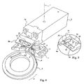
- a position active is for example shown in Figures 4 and 5.
- the active position corresponds to the disposition of one end 4a of the retractable finger 4 on the path of a drive member 6 rotating with the steering column 2.
- the OR the electrical contacts controlled by the lever 3 are thus deactivated.
- the steering column 2 comprises two members 6 symmetrically distributed around the axis of said column Direction 2.
- the guide piece 5 is pivotally mounted around a fixed axis 7 in the housing 1 against spring return forces 8.
- the springs 8 allow to retract the guide piece 5 by pivoting under the action of the drive member 6 and therefore to retract the retractable finger 4 when holding lever 3 in its left position or right, when rotating in the opposite direction of the steering column 2.
- the pivoting of the guide piece 5 is in one direction or in the other against spring return forces 8. It is thus possible to continue the rotation in the opposite direction of the steering column 2 and therefore drive members 6, even when the finger retractable 4 is held in a position on the path of the drive member 6. It is more precisely the end 4a of the finger retractable 4 which abuts against the drive member 6, which in continuing its rotation rotates the guide piece 5 and avoids any rupture or deformation of the constituent parts of the device according to the invention.
- the retractable finger 4 slides on the guide piece 5 radially by relative to the steering column 2. This sliding of the retractable finger 4 is against positioning spring return forces 9 connecting said retractable finger 4 on each side to the guide piece 5.
- the retractable finger 4 When the lever 3 is in its central position, the retractable finger 4 is held in a position releasing the trajectory of the organ 6. This position is obtained thanks to the springs of 9 positioning in extension.
- a displacement or more precisely a pivoting of the lever 3 relative to its pivot axis I in a left or right position automatically drives the slide retractable finger 4 in its active position in which its end 4a is positioned on the path of the drive member 6, and this thanks to positioning springs 9.
- the lever 3 has at its end 3a located in the vicinity of the steering column an indexing finger 10 likely to move in the longitudinal direction of the lever 3 against a restoring force of a compression spring 11.
- the end of the indexing finger 10 comes resting on an indexing surface 12 secured to the fixed housing 1.
- the cooperation between the indexing surface 12 and the indexing finger 10 allows the lever 3 to move between the central stable positions, left and right.
- Such an indexing system is known as such.
- the retractable finger 4 slides against return forces of the positioning springs 9, which push a support edge 13 provided on the retractable finger 4 against a stop 14 moving with the lever 3.
- the support edge 13 is for example constituted by a salient pivot protruding up the retractable finger 4.
- the abutment 14 has a relief surface in relief, resulting in sliding the retractable finger 4 between its inactive position and its position active.
- the abutment 14 has for this purpose a central boss 15 against which bears the support edge 13 in the inactive position of the finger retractable 4.
- the abutment 14 is for example made with a window 16 arranged in a part 3b secured to the lever 3.
- the housing 1 advantageously has an opening 17 in an arc of circle in which extends a fixed wall 18 secured to the housing 1 and against which the springs 8 bear with one of their ends.
- the other ends of the springs 8 rest on the guide piece 5.
- the springs 8 are preferably mounted prestressed in the room 5, and during the positioning of the guide piece 5 on the casing 1, the springs with one of their support plane, are positioned against the fixed wall 18.
- the opening 17 provides access under the room of guiding 5 and facilitating the positioning of the springs 8.
- the pivot plane of the guide piece 5 is for example inclined with respect to a cross-sectional plane and orthogonal to the steering column 2.
- the guide piece 5 also has a sliding surface 19 extending in a plane orthogonal to the axis of the steering column 2. This arrangement allows the retractable finger 4 to slide in a plane orthogonal to the axis of the steering column 2.
- FIG. 5 represents a detail of FIG. 4, seen from below, and shows more precisely the arrangement and positioning of the finger retractable 4 relative to the lever 3.
- the retractable finger 4 has a sliding finger 20 for engaging in a slot 19a formed in the sliding surface 19.
- the sliding finger 20 advantageously has a longitudinal section T-shaped thus avoiding any separation with the guide part 5.
- the slot of slide 19a of course has a complementary shape to that of the sliding finger 20.
- Figures 4 and 5 show the device according to the invention with the retractable finger 4 in an active position.
- the complementary end 4b of the retractable finger 4 is positioned against an edge 21 of the lever 3.
- the unlocking mechanism by through the driving member 6, during a rotation in the direction R (see figure 4) of the steering column 2, push against the end 4a of the retractable finger 4.
- the retractable finger 4 tends to pivot around its support edge 13 and push on the edge 21 of the lever 3.
- the latter is then driven into its central position in simultaneously driving by sliding the retractable finger 4 in its inactive position, corresponding to the positioning of the support edge 13 on the boss 15.
- the return to its central position of the lever 3 is done together with the displacement of the indexing finger 10 urged by the compression spring 11 against the indexing surface 12.
- the efforts to provide by the retractable finger 4 when such a return are due to this phenomenon.
Landscapes
- Engineering & Computer Science (AREA)
- Mechanical Engineering (AREA)
- Lock And Its Accessories (AREA)
- Steering Controls (AREA)
Claims (10)
- Fahrtrichtungsanzeigevorrichtung für Fahrzeuge umfassend:dadurch gekennzeichnet, dass das Führungsteil (5) gegen die Rückstellkräfte von Federn (8) verschwenkt und die einzige mechanische Verbindung zwischen dem Gehäuse (1) und dem zurückziehbaren Finger (4) darstellt.ein Gehäuse (1) das fest in der Nähe einer Lenksäule (2) montiert ist,einen Betätigungshebel (3), der auf dem Gehäuse (1) montiert ist und zwischen drei stabilen Positionen verstellbar ist, einer zentralen Position, einer Linksstellung und einer Rechtsstellung, wobei die Anordnung in der Linksstellung oder der Rechtsstellung einer Betätigung wenigstens eines elektrischen Kontakts entspricht,einen Freigabemechanismus der den Hebel in seine zentrale Position ausgehend von der Linksstellung oder Rechtsstellung im Falle einer umgekehrten Rotation der Lenksäule (2) zurückführt, wobei dieser Freigabemechanismus einen zurückziehbaren Finger (4) enthält, der vom Hebel (3) mitgenommen wird und mit einem Führungsteil (5) verbunden ist,wobei das Führungsteil (5) schwenkbar um eine feste Achse (7) im Gehäuse (1) gelagert ist, derart, dass es unter der Wirkung des Mitnahmeorgans (6) eingezogen wird und dass demzufolge der zurückziehbare Finger (4) eingezogen wird im Falle des Haltens des Hebels (3) in seiner Rechtsoder Linksstellung bei der Rotation im umgekehrten Sinne der Lenksäule (2),wobei der zurückziehbare Finger (4) schwenkbar und gleitend auf dem Führungsteil (5) montiert ist,wobei der zurückziehbare Finger (4) beweglich zwischen einer inaktiven Stellung entsprechend einer Zentralstellung des Hebels (3) und einer aktiven Stellung entsprechend einer Links- oder Rechtsstellung des Hebels (3) beweglich ist,und wobei die aktive Position der Anordnung einer Extremität (4a) des zurückziehbaren Fingers (4) auf dem Weg eines Mitnahmeorgans (6) entspricht das sich mit der Lenksäule (2) dreht und eine Aktion des Mitnahmeorgans (6) auf den zurückziehbaren Finger (4) den Hebel (3) in seine Zentralposition zurückführt,
- Vorrichtung nach Anspruch 1, dadurch gekennzeichnet, dass sie Positionierfedern (9) enthält die den zurückziehbaren Finger (4) mit dem Führungsteil verbinden.
- Vorrichtung nach Anspruch 2, dadurch gekennzeichnet, dass der zurückziehbare Finger (4) gegen die Rückstellkräfte von Positionierfedern (9) gleitet, die ein Anschlagteil (13) am zurückziehbaren Finger (4) gegen ein Widerlager (14) drücken das sich mit dem Hebel (3) verschiebt, wobei das genannte Widerlager (14) eine Reliefanlagefläche aufweist, die durch Verschiebung den zurückziehbaren Finger (4) zwischen seiner aktiven Stellung und seiner inaktiven Stellung verschiebt.
- Vorrichtung nach Anspruch 3, dadurch gekennzeichnet, dass das Widerlager (14) durch ein Fenster (16) in einem fest mit dem Hebel (3) verbundenen Teil (3b) realisiert ist.
- Vorrichtung nach einem der Ansprüche 1 bis 4, dadurch gekennzeichnet, dass der zurückziehbare Finger (4) auf dem Führungsteil (5) radial gegen die Lenksäule (2) gleitet.
- Vorrichtung nach einem der Ansprüche 1 bis 5, dadurch gekennzeichnet, dass der Hebel (3) an seinem Ende (3a) in der Nähe der Lenksäule (2) einen Verriegelungsfinger (10) enthält der in der Lage ist sich in Längsrichtung des Hebels (3) gegen eine Rückstellkraft einer Kompressionsfeder (11) zu verschieben und in Eingriff zu treten mit einer fest mit dem Gehäuse (1) verbundenen Verriegelungsfläche.
- Vorrichtung nach einem der Ansprüche 1 bis 6, dadurch gekennzeichnet, dass das Gehäuse (1) eine Öffnung (17) in Form eines Kreisbogens aufweist, in welche sich eine niedrige Wand (18) erstreckt die mit dem Gehäuse (1) verbunden ist, gegen welche sich die Federn (8) mit ihren Enden abstützen, während ihre anderen Enden sich am Führungsteil (5) abstützen.
- Vorrichtung nach Anspruch 7, dadurch gekennzeichnet, dass die Federn (8) vorgespannt im Führungsteil (5) montiert sind und sich an der niedrigen Wand (18) abstützen an dem das Führungsteil (5) auf dem Gehäuse (1) platziert worden ist.
- Vorrichtung nach einem der Ansprüche 1 bis 8, dadurch gekennzeichnet, dass die Schwenkebene des Führungsteils (5) gegenüber einer transversalen und orthogonalen Schnittebene der Lenksäule (2) geneigt ist.
- Vorrichtung nach Anspruch 9, dadurch gekennzeichnet, dass das Führungsteil (5) eine Kulissenfläche (19) aufweist die sich in einer Ebene orthogonal zur Achse der Lenksäule (2) erstreckt und es somit dem zurückziehbaren Finger (4) ermöglicht in der gleichen Ebene zu gleiten.
Applications Claiming Priority (2)
| Application Number | Priority Date | Filing Date | Title |
|---|---|---|---|
| FR0302966 | 2003-03-07 | ||
| FR0302966A FR2851965B1 (fr) | 2003-03-07 | 2003-03-07 | Dispositif de deverouillage d'un indicateur de changement de direction |
Publications (2)
| Publication Number | Publication Date |
|---|---|
| EP1454795A1 EP1454795A1 (de) | 2004-09-08 |
| EP1454795B1 true EP1454795B1 (de) | 2005-04-27 |
Family
ID=32799660
Family Applications (1)
| Application Number | Title | Priority Date | Filing Date |
|---|---|---|---|
| EP20040290628 Expired - Lifetime EP1454795B1 (de) | 2003-03-07 | 2004-03-08 | Rückstelleinrichtung für einen Fahrtrichtungsanzeiger |
Country Status (3)
| Country | Link |
|---|---|
| EP (1) | EP1454795B1 (de) |
| DE (1) | DE602004000007T2 (de) |
| FR (1) | FR2851965B1 (de) |
Families Citing this family (1)
| Publication number | Priority date | Publication date | Assignee | Title |
|---|---|---|---|---|
| KR101359282B1 (ko) * | 2011-02-25 | 2014-02-05 | 알프스 덴키 가부시키가이샤 | 턴 시그널 스위치 장치 |
Family Cites Families (4)
| Publication number | Priority date | Publication date | Assignee | Title |
|---|---|---|---|---|
| DE8504080U1 (de) * | 1985-02-14 | 1985-12-19 | Leopold Kostal GmbH & Co KG, 5880 Lüdenscheid | Lenkstockschalter zur Fahrtrichtungsanzeige an Kraftfahrzeugen |
| FR2718088B1 (fr) * | 1994-03-31 | 1996-06-28 | Jaeger | Commutateur électrique pour l'alimentation des indicateurs de changement de direction d'un véhicule automobile. |
| DE19904620B4 (de) * | 1999-02-05 | 2005-12-29 | Valeo Schalter Und Sensoren Gmbh | Einrastvorrichtung mit Rückstellfunktion für einen Blinkerschalter |
| JP3854427B2 (ja) * | 1999-06-16 | 2006-12-06 | アルプス電気株式会社 | ターンシグナルスイッチ装置 |
-
2003
- 2003-03-07 FR FR0302966A patent/FR2851965B1/fr not_active Expired - Fee Related
-
2004
- 2004-03-08 EP EP20040290628 patent/EP1454795B1/de not_active Expired - Lifetime
- 2004-03-08 DE DE602004000007T patent/DE602004000007T2/de not_active Expired - Lifetime
Also Published As
| Publication number | Publication date |
|---|---|
| FR2851965B1 (fr) | 2006-04-28 |
| DE602004000007D1 (de) | 2005-06-02 |
| FR2851965A1 (fr) | 2004-09-10 |
| EP1454795A1 (de) | 2004-09-08 |
| DE602004000007T2 (de) | 2006-02-23 |
Similar Documents
| Publication | Publication Date | Title |
|---|---|---|
| EP1956619B1 (de) | Verriegelungsschalter | |
| EP2332158B1 (de) | Nothalteinrichtung | |
| FR3108566A1 (fr) | Système de redressement réactif et dissipatif d’un siège de véhicule | |
| FR2821108A1 (fr) | Serrure d'ouvrant de vehicule automobile a maneton debrayable | |
| EP1454795A1 (de) | Rückstelleinrichtung für einen Fahrtrichtungsanzeiger | |
| FR2909167A1 (fr) | Dispositif de nivellement laser | |
| EP2398029B1 (de) | Schalter mit monostabiler Bedienung und bistabilem Kontakt | |
| EP1772312B1 (de) | Fahrtrichtungsanzeiger für Kraftfahrzeuge | |
| EP2564408B1 (de) | Nothalteinrichtung | |
| EP1889992B1 (de) | Einklappbarer Schlüssel | |
| EP0631912B1 (de) | Lenkradschloss für Kraftfahrzeuge | |
| EP0906997A1 (de) | Verriegelungsvorrichtung mit einem nockenbetätigten Übertragungselement | |
| FR2999779A1 (fr) | "agencement de commutateur electrique et dispositif pour la commande d'un appareil comportant un tel agencement" | |
| EP1665316A1 (de) | Abschalteinrichtung für elektrischen strom mit vollständiger diskrimination von zuständen | |
| EP1542252B1 (de) | Bedienvorrichtung für Kraftfahrzeug | |
| EP1894785A1 (de) | Gepäckabdeckung für Kraftfahrzeug, die zwei mit Gelenken versehene Aufrollvorrichtungen und ein elastisches Rückholmittel für diese umfasst | |
| FR2846468A1 (fr) | Organe de commande a bouton de manipulation rotatif autour de plusieurs axes | |
| FR2496022A1 (fr) | Dispositif de commande pour avertisseurs optiques et sonores | |
| EP0363278B1 (de) | Innenbeleuchtungseinrichtung für Fahrzeuge | |
| EP4043290B1 (de) | Haltevorrichtung für ein tragbares elektronisches gerät in einem kraftfahrzeug | |
| EP2564409B1 (de) | Not-aus-vorrichtung mit sichermontierbaren schaltungsanordnungen | |
| EP1571020B1 (de) | Steuerungsvorrichtung, insbesondere für eine Lüftungs-, Heizung- oder Klimaanlage, mit einer Krafthilfeeinrichtung | |
| FR2967119A1 (fr) | Module d'actionnement electromecanique, et frein de parc le comportant | |
| FR3155494A1 (fr) | Module multifonctionnel a robustesse amelioree pour porte louvoyante coulissante, et vehicule ainsi equipe | |
| EP1486376B1 (de) | Steueranordnung zum Aktivieren bzw. Deaktivieren von Funktionen eines Fahrzeuges |
Legal Events
| Date | Code | Title | Description |
|---|---|---|---|
| PUAI | Public reference made under article 153(3) epc to a published international application that has entered the european phase |
Free format text: ORIGINAL CODE: 0009012 |
|
| 17P | Request for examination filed |
Effective date: 20040406 |
|
| AK | Designated contracting states |
Kind code of ref document: A1 Designated state(s): AT BE BG CH CY CZ DE DK EE ES FI FR GB GR HU IE IT LI LU MC NL PL PT RO SE SI SK TR |
|
| AX | Request for extension of the european patent |
Extension state: AL LT LV MK |
|
| GRAP | Despatch of communication of intention to grant a patent |
Free format text: ORIGINAL CODE: EPIDOSNIGR1 |
|
| GRAS | Grant fee paid |
Free format text: ORIGINAL CODE: EPIDOSNIGR3 |
|
| GRAA | (expected) grant |
Free format text: ORIGINAL CODE: 0009210 |
|
| AK | Designated contracting states |
Kind code of ref document: B1 Designated state(s): DE FR |
|
| REG | Reference to a national code |
Ref country code: IE Ref legal event code: FG4D Free format text: LANGUAGE OF EP DOCUMENT: FRENCH |
|
| AKX | Designation fees paid |
Designated state(s): DE FR |
|
| REF | Corresponds to: |
Ref document number: 602004000007 Country of ref document: DE Date of ref document: 20050602 Kind code of ref document: P |
|
| PLBE | No opposition filed within time limit |
Free format text: ORIGINAL CODE: 0009261 |
|
| STAA | Information on the status of an ep patent application or granted ep patent |
Free format text: STATUS: NO OPPOSITION FILED WITHIN TIME LIMIT |
|
| 26N | No opposition filed |
Effective date: 20060130 |
|
| REG | Reference to a national code |
Ref country code: FR Ref legal event code: PLFP Year of fee payment: 13 |
|
| REG | Reference to a national code |
Ref country code: FR Ref legal event code: PLFP Year of fee payment: 14 |
|
| PGFP | Annual fee paid to national office [announced via postgrant information from national office to epo] |
Ref country code: FR Payment date: 20170327 Year of fee payment: 14 |
|
| PG25 | Lapsed in a contracting state [announced via postgrant information from national office to epo] |
Ref country code: FR Free format text: LAPSE BECAUSE OF NON-PAYMENT OF DUE FEES Effective date: 20180331 |
|
| PGFP | Annual fee paid to national office [announced via postgrant information from national office to epo] |
Ref country code: DE Payment date: 20210420 Year of fee payment: 18 |
|
| REG | Reference to a national code |
Ref country code: DE Ref legal event code: R119 Ref document number: 602004000007 Country of ref document: DE |
|
| PG25 | Lapsed in a contracting state [announced via postgrant information from national office to epo] |
Ref country code: DE Free format text: LAPSE BECAUSE OF NON-PAYMENT OF DUE FEES Effective date: 20221001 |