EP1769998B1 - Layout structure for motor-driven power steering unit controller - Google Patents
Layout structure for motor-driven power steering unit controller Download PDFInfo
- Publication number
- EP1769998B1 EP1769998B1 EP06018143A EP06018143A EP1769998B1 EP 1769998 B1 EP1769998 B1 EP 1769998B1 EP 06018143 A EP06018143 A EP 06018143A EP 06018143 A EP06018143 A EP 06018143A EP 1769998 B1 EP1769998 B1 EP 1769998B1
- Authority
- EP
- European Patent Office
- Prior art keywords
- motor
- driven power
- power steering
- controller
- shaft
- Prior art date
- Legal status (The legal status is an assumption and is not a legal conclusion. Google has not performed a legal analysis and makes no representation as to the accuracy of the status listed.)
- Expired - Fee Related
Links
Images


Classifications
-
- B—PERFORMING OPERATIONS; TRANSPORTING
- B62—LAND VEHICLES FOR TRAVELLING OTHERWISE THAN ON RAILS
- B62D—MOTOR VEHICLES; TRAILERS
- B62D5/00—Power-assisted or power-driven steering
- B62D5/04—Power-assisted or power-driven steering electrical, e.g. using an electric servo-motor connected to, or forming part of, the steering gear
- B62D5/0403—Power-assisted or power-driven steering electrical, e.g. using an electric servo-motor connected to, or forming part of, the steering gear characterised by constructional features, e.g. common housing for motor and gear box
- B62D5/0406—Power-assisted or power-driven steering electrical, e.g. using an electric servo-motor connected to, or forming part of, the steering gear characterised by constructional features, e.g. common housing for motor and gear box including housing for electronic control unit
-
- B—PERFORMING OPERATIONS; TRANSPORTING
- B62—LAND VEHICLES FOR TRAVELLING OTHERWISE THAN ON RAILS
- B62K—CYCLES; CYCLE FRAMES; CYCLE STEERING DEVICES; RIDER-OPERATED TERMINAL CONTROLS SPECIALLY ADAPTED FOR CYCLES; CYCLE AXLE SUSPENSIONS; CYCLE SIDE-CARS, FORECARS, OR THE LIKE
- B62K5/00—Cycles with handlebars, equipped with three or more main road wheels
- B62K5/01—Motorcycles with four or more wheels
-
- B—PERFORMING OPERATIONS; TRANSPORTING
- B62—LAND VEHICLES FOR TRAVELLING OTHERWISE THAN ON RAILS
- B62K—CYCLES; CYCLE FRAMES; CYCLE STEERING DEVICES; RIDER-OPERATED TERMINAL CONTROLS SPECIALLY ADAPTED FOR CYCLES; CYCLE AXLE SUSPENSIONS; CYCLE SIDE-CARS, FORECARS, OR THE LIKE
- B62K5/00—Cycles with handlebars, equipped with three or more main road wheels
- B62K5/08—Cycles with handlebars, equipped with three or more main road wheels with steering devices acting on two or more wheels
Description
- The present invention relates to a layout structure for a motor-driven power steering unit controller of an all terrain vehicle.
-
JP 02663454 B claim 1, discloses a conventional motor-driven power steering unit controller for controlling a drive motor. -
Fig. 6 ofJP 026 63 454 B controller 26 for controlling a drive motor 23 provided in a motor-driven power steering device. - A saddle-ride type all-terrain vehicle shown in
Fig. 1 ofJP 02 663 454 B controller 26, so that the specific layout of thecontroller 26 is not clear. - The saddle-ride type vehicle, for running on bad-conditioned grounds, may run across or longitudinally through a river, for example. Therefore, various component parts with which the vehicle is equipped, particularly electrical equipments, must be laid out taking into account the water surface on the assumption that the vehicle may run across or longitudinally through rivers and the like.
- Document
US 2004/0080186 A1 discloses a compartment for a recreational vehicle in order to facilitate access to a number of components associated with the engine. Said document further shows an electrical component cover which preferably covers the fuse box and ECU for the ATV for preventing splash water from entering the service centre. - It is an object of the present invention to provide an All Terrain Vehicle with a layout structure for a motor-driven power steering unit controller taking into account the water surface on the assumption that the vehicle may run across or longitudinally through rivers and the like.
- The invention as set forth in
claim 1 is characterized in that, in an all terrain vehicle comprising a steering shaft rotatably supported on a vehicle body frame, a steering bar handle attached to the upper end of the steering shaft, a motor-driven power steering unit mounted onto the lower end of the steering shaft, and at least two steerable front wheels connected to said steering shaft, a controller for controlling the motor-driven power steering unit is disposed on the front side relative to an oil cooler for cooling an engine oil and both, said controller and said oil cooler are disposed on the front side relative to the steering shaft and above said motor-driven power steering unit which is placed at the level of a submergence limit of the vehicle, wherein said submergence limit is at an air opening end of an air vent tube provided for a carburetor, or at a tail pipe opening of a muffler. - In operation, it is ensured that where the submergence of the controller is expected, the driver can drive the vehicle while checking the positional relationship between the controller provided on the front side relative to the steering shaft and the water surface. Further, since the controller is located at a high position above the submergence limit, the controller can be prevented from being submerged.
- Additionally, when the warmed engine oil is circulated through the oil cooler, the heat of the oil cooler is carried rearwards from the oil cooler by the running airflow, so that the controller laid out on the front side relative to the oil cooler is not influenced by the heat.
- In operation of the submergence limit, it's ensured that the submergence of the inside of the carburetor or the inside of the muffler can be obviated by paying attention to the submergence limit at the time of running through rivers, damp grounds and the like.
- The invention as set forth in claim 2 is characterized in that the lower end of the steering shaft is rotatably supported on a housing added, in a turret-like form, to the motor-driven power steering unit, a rear wall of the housing is provided with an opening, and a wire for connecting the motor-driven power steering unit and the controller is passed through the opening.
- In operation of the opening, with the opening provided in the rear wall of the housing, flying stones, rainwater, dust and the like coming from the front side of the vehicle would not easily enter into the housing; besides, since the wire for connecting the motor-driven power steering unit and the controller is passed through the opening, the laying of the wire can be conducted easily.
-
Fig. 1 is a side view of a vehicle configured by adopting a layout structure for a motor-driven power steering unit controller according to the present invention. -
Fig. 2 is a side view of a first essential part of the vehicle according to the present invention. -
Fig. 3 is a side view of a second essential part of the vehicle according to the present invention. -
Fig. 4 is a front view of an essential part of the vehicle according to the present invention. -
Fig. 5 is a plan view of an essential part of the vehicle according to the present invention. -
Fig. 6 shows operation diagrams showing the layout structure for the controller according to the present invention. - A best mode for carrying out the present invention will be described below, based on the accompanying drawings. Incidentally, the drawings are to be looked at according to the posture of symbols.
Fig. 1 is a side view of a vehicle configured by adopting a layout structure for a motor-driven power steering unit controller according to the present invention. An all-terrain vehicle 10 as the vehicle is a four-wheel-drive vehicle in which apower unit 14 composed of anengine 12 and atransmission 13 is mounted on a central portion of avehicle body frame 11, a front finalspeed reduction gear 17 is connected to a front portion of thetransmission 13 through afront propeller shaft 16, left and right front wheels 18, 18 connected to the front finalspeed reduction gear 17 through a drive shaft (not shown), a rear finalspeed reduction gear 22 is connected to a rear portion of thetransmission 13 through arear propeller shaft 21, left and right rear wheels 23, 23 are connected to the rear finalspeed reduction gear 22 through a drive shaft (not shown), and a motor-drivenpower steering unit 24 is provided for alleviating a steering force for steering the front wheels 18, 18. In the figure,symbol 25 denotes a controller for controlling the motor-drivenpower steering unit 24, and is laid out on the front side relative to anoil cooler 26 and above ahorizontal line 27 indicating the submergence limit.
Thehorizontal line 27 is a line passing through the submergence limit set at the position of an opening (more specifically, the lower end of the opening) of atail pipe 69a of amuffler 69 which will be described later. - The
vehicle body frame 11 includes: a left-right pair of uppermain frames 31, 32 (onlysymbol 31 on the viewer's side is shown) extended in the front-rear direction; afront frame 33 inverted U-shaped in front view which is connected to the front ends of the uppermain frames main frames 34, 36 (onlysymbol 34 on the viewer's side is shown) connected respectively to the lower ends of thefront frame 33 and intermediate portions of the uppermain frames upper frames 41, 42 (onlysymbol 41 on the viewer's side is shown) connected respectively to the upper end of thefront frame 33 and the uppermain frames steering shaft 38 fitted with asteering bar handle 37 at the upper end thereof; a left-right pair ofinclined frames 43, 44 (onlysymbol 43 on the viewer's side is shown) extended rearwardly downwards from the front ends of the uppermain frames main frames 34, 36; and a left-right pair of subinclined frames 46, 47 (onlysymbol 46 on the viewer's side is shown) bridgingly connected respectively to intermediate portions of theinclined frames 43, 44 and thefront frame 33 to thereby support a lower portion of the motor-drivenpower steering unit 24. - Here,
symbol 55 denotes a front carrier; 56 denotes a front fender covering the upper and rear sides of the front wheels 18; 57 denotes a fuel tank; 58 denotes a seat; 61 denotes a rear carrier; 62 denotes a carburetor connected to the rear portion side of acylinder head 63 of theengine 12; 64 denotes a cylinder portion projecting to the upper side of thepower unit 24 and including thecylinder head 63; 66 denotes an air cleaner connected to thecarburetor 62 through aconnecting tube 67; 68 denotes an exhaust pipe extended toward the vehicle rear side from a front portion of thecylinder head 63; 69 denotes the muffler connected to the rear end of theexhaust pipe 68; 69a denotes a tail pipe provided at the rear end of themuffler 69; 71 denotes a swing arm for supporting the rear wheels 23, 23 swingably relative to the lowermain frames 34, 36; 72, 72 (onlysymbol 72 on the viewer's side is shown) denote a left-right pair of rear cushion units bridgingly attached to theswing arm 71 and the uppermain frames power unit 14; 74 denotes a rear fender covering the upper and front sides of the rear wheels 23; 75 denotes a step floor; 76 denotes a skid plate covering front lower portions of the left and right lowermain frames 34, 36 and the front side of the lowermain frames 34, 36. -
Fig. 2 is a side view of an essential part of the vehicle according to the present invention, and shows that an intermediate portion of thesteering shaft 38 is rotatably supported by an upper portion of thevehicle body frame 11, aninput shaft 81 provided at an upper portion of the motor-drivenpower steering unit 24 is connected to the lower end of thesteering shaft 38, a lower portion of the motor-drivenpower steering unit 24 is mounted onto a lower portion of thevehicle body frame 11, and anoutput shaft 82 provided at a lower portion of the motor-drivenpower steering unit 24 is rotatably supported by a lower portion of thevehicle body frame 11. - The
steering shaft 38 is composed of anupper shaft 85 fitted with the steering bar handle 37 (seeFig. 1 ) at the upper end thereof, and alower shaft 86 the upper end of which is serration connected to the lower end of theupper shaft 85 and the lower end of which is serration connected to theinput shaft 81. - The
upper shaft 85 is a member rotatably attached, through an upper bearingportion 91, to asteering support bracket 88 bridgingly attached to the left and right frontupper frames upper shaft 85 is provided at its upper end with afemale serration 85a for connection with amale serration 86a provided at the upper end of thelower shaft 86, and is provided with an expandingslot 85b extending in the axial direction and communicating with both thefemale serration 85a side and the outer peripheral surface side. Projectedportions 85c, 85d (onlysymbol 85d on the depth side is shown) are integrally formed respectively at both edge portions of the expandingslot 85b.Bolt insertion holes 85e are bored in the projectedportions 85c, 85d,bolts 92 are passed through thebolt insertion holes 85e. Nuts (not shown) are screw engaged with the tip ends of thebolts 92, whereby the upper end of theinput shaft 81 is fastened by the lower end of theupper shaft 85. Incidentally,symbol 86A denotes a positioning portion provided in thelower shaft 86 for positioning by putting the tip end of theupper shaft 85 into abutment thereon. - The
steering support bracket 88 is composed of across member 93 bridgingly connected to the frontupper frames right boss portions 94, 94 (onlysymbol 94 on the viewer's side is shown) attached to thecross member 93.Bolts 95 are screw engaged with theboss portions portion 91 is fixed.
The upper bearingportion 91 is composed of a bush (not shown) slidably fitted over theupper shaft 85, and a pair ofmetallic holders - The
lower shaft 86 is provided at its lower portion with ashaft portion 86b, and at its intermediate portion with an L-shaped projectedportion 86c projected rearwards and being L-shaped in section. Theshaft portion 86b is provided with afemale serration 86d for connection with amale serration 81a formed at the tip end of theinput shaft 81. - The motor-driven
power steering unit 24 has, annexed thereto, ahousing 101 covering an upper portion thereof. Thehousing 101 is a member a lower portion of which is attached to agear case 102 of the motor-drivenpower steering unit 24 by a plurality ofbolts 103 and an upper portion of which rotatably supports theshaft portion 86b of thelower shaft 86 through an intermediate bearingportion 104. - The intermediate bearing
portion 104 is composed of a multi-row typeupper bearing 107 fitted in ahole 101a opened in an upper portion of thehousing 101 and fitted over theshaft portion 86b, astop ring 108 for positioning one end of theupper bearing 107, aseal member 111 fitted in one end portion of thehole 101a adjacently to thestop ring 108, acollar 112 fitted over theshaft portion 86b and abutting on the other end of theupper bearing 107, and a nut 113 screw engaged with amale screw 86f at the tip end of theshaft portion 86b to thereby pressing and fixing the other end of the upper bearing 107 through thecollar 112. Incidentally,symbol 86B is a positioning portion formed in theshaft portion 86b for positioning by putting one end of the upper bearing 107 into abutment thereon. - The motor-driven
power steering unit 24 is composed of the above-mentionedinput shaft 81 andoutput shaft 82, atorque sensor portion 121 for detecting a steering torque, and apower assist portion 122 for generating power for assisting a steering force. Thepower assist portion 122 is controlled by a controller (not shown), based on the steering torque detected by thetorque sensor portion 121 and the like. - The
torque sensor portion 121 has atorsion bar 126 for connecting theinput shaft 81 and theoutput shaft 82.
When theinput shaft 81 is rotated by an operation on the steering bar handle 37 (seeFig. 1 ), a relative rotational angle is generated between theinput shaft 81 and theoutput shaft 82, and thetorsion bar 126 is twisted. The twisting amount (torsion) is converted into a torque, whereby the steering torque is determined. - The
power assist portion 122 is composed of anelectric motor 128, and a clutch (not shown) and a speed reduction gear (not shown; composed of a worm gear and a worm wheel) which are interposed between an output shaft of theelectric motor 128 and theoutput shaft 82. - The motor-driven
power steering unit 24 has a configuration in which thegear case 102 on the front side relative to theoutput shaft 82 is attached to a plate-likelower bracket 131 provided at the subinclined frames 46, 47, through afront support member 132 by abolt 133, and thegear case 102 on the rear side relative to theoutput shaft 82 is attached by abolt 136 to arear support member 134 provided at the subinclined frames 46, 47. - Thus, the motor-driven
power steering unit 24 is a member in which a lower portion of thegear case 102 is supported by thefront support member 132 and therear support portion 134 at two front and rear positions, with theoutput shaft 82 therebetween. - The controller controls the
power assist portion 122, based on the steering torque detected by thetorque sensor portion 121, a steering angle detected by a steering angle sensor (not shown), the vehicle velocity of the all-terrain vehicle 10 (seeFig. 1 ), and the like. - A
lower bearing portion 140 for rotatably supporting theoutput shaft 82 includes ashaft support member 141 attached to a central portion of thelower bracket 131, an automatic center adjusting typelower bearing 142 attached to theshaft support member 141 so as to rotatably support theoutput shaft 82, and aseal member 143 for protecting thelower bearing 142 from dust and the like. Incidentally,symbol 145 denotes a collar. - The
shaft support member 141 is provided on the vehicle front side with a lower projectedportion 141a projected to the lower side substantially along theoutput shaft 82.
Symbol 147 denotes a center arm, which is provided with afemale spline 147a for spline connection with amale spline 82a formed at a lower end portion of theoutput shaft 82. -
Symbol 151 denotes a ball joint provided at its end portion with abolt portion 151a, which is attached to a rear portion of thecenter arm 147 by anut 152.
Symbol 154 denotes a nut, which is screw engaged with a male screw provided at the tip end of theoutput shaft 82, whereby thecenter arm 147 is fixed to theoutput shaft 82.
The lower projectedportion 141 of theshaft support member 141 and thecenter arm 147 constitute a lowersteering handle stopper 156. Incidentally,symbol 158 denotes a wire for connection between the motor-drivenpower steering unit 24 and the controller 25 (seeFig. 1 ). -
Fig. 3 is a side view of a second essential part of the vehicle according to the present invention, and shows that anupper bracket 171 is attached to an upper portion of thefront frame 33, anoil cooler 26 for cooling a lubricating oil in the power unit 14 (seeFig. 1 ) and an electricalequipment storage box 174 are attached to theupper bracket 171 through anupper stay 172, and thecontroller 25 for the motor-drivenpower steering unit 24 is contained in the electricalequipment storage box 174. Incidentally,symbols engine 12 into theoil cooler 26. - The electrical
equipment storage box 174, particularly thecontroller 25 therein, is disposed on the vehicle front side relative to theoil cooler 26 and above thehorizontal line 27 indicative of the limit in regard of submergence of the vehicle, i.e., the submergence limit. - A
horizontal line 180 passing through the lower ends 31b, 32b (onlysymbol 31b on the viewer's side is shown) of upperstraight portions 31a, 32a (onlysymbol 31a on the viewer's side is shown) of the uppermain frames 31, 32 (onlysymbol 31 on the viewer's side is shown) is located above thehorizontal line 27 passing through the submergence limit, and thecontroller 25 is located above thehorizontal line 180. - The submergence limit is at opening ends (namely,
openings 178a, 179a (symbol 179a is not shown)) ofair vent tubes carburetor 62 to the atmosphere, or at thetail pipe 69a (seeFig. 1 ) of the muffler 69 (seeFig. 1 ). Here, of ahorizontal line 185 and thehorizontal line 27 passing through the lower ends of theopenings 178a, 179a, thehorizontal line 27 located at the lowermost position serves as the submergence limit of the vehicle. - The
air vent tube 178 has one end portion connected to the right side surface of thecarburetor 62, and has theopening 178a at the other end portion opened on the left side surface side of thecarburetor 62. Similarly, theair vent tube 179 has oneend portion 179b connected to the left side surface of thecarburetor 62, and has the opening 179a at the other end portion opened on the right side surface side of thecarburetor 62. The lower ends of theopenings 178a, 179a are at the same height.
InFig. 3 , part of the vehicle component parts is omitted, for easy comparison between the height of theopenings 178a, 179a of theair vent tubes carburetor 62 and the height of thecontroller 25. -
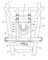
Fig. 4 is a front view of an essential part of the vehicle according to the present invention, and shows that thehousing 101 is attached to the motor-drivenpower steering unit 24 by a plurality ofbolts 103, and an upper portion of the motor-drivenpower steering unit 24 is covered with thehousing 101. - With the upper portion of the motor-driven
power steering unit 24 thus covered with thehousing 101, the motor-drivenpower steering unit 24 can be protected from flying stones, rainwater, dust and the like. -
Fig. 5 is a plan view of an essential part of the vehicle according to the present invention, and shows that an upper portion of thehousing 101 and the L-shaped projectedportion 86c of thelower shaft 86 constitute an uppersteering handle stopper 161 for restricting the rotating range of thesteering bar handle 37. - The operation of the layout structure for the
controller 25 as above-described will be described below.
Figs. 6(a) and 6(b) are operation diagrams showing the layout structure for the controller according to the present invention.
InFig. 6(a) , during running of the vehicle, the temperature of the engine oil in the engine is raised due to the operation of the engine; in view of this, the oil is circulated in theoil cooler 26 to release heat, whereby the engine oil is cooled. The heat of theoil cooler 26 is carried toward the rear side of theoil cooler 26 as indicated by arrows A and B by the running airflow coming from the vehicle front side as indicated by the void arrow. Therefore, there is no fear that thecontroller 25 in the electricalequipment storage box 174 might be influenced by the heat of theoil cooler 26. - In
Fig. 6(b) , therear wall 101h of thehousing 101 covering an upper portion of the motor-drivenpower steering unit 24 is provided with anopening 101j, and awire 158 for connection between the motor-drivenpower steering unit 24 and thecontroller 25 is passed through theopening 101j, whereby it can be made difficult for flying stones, rainwater, dust and the like to enter into thehousing 101. In addition, with thehousing 101 provided with theopening 101j, the laying of thewire 158 can be carried out readily. - Besides, even if the
water surface 181 in the case where the vehicle is submerged has reached thehorizontal line 27 indicating the submergence limit of the vehicle, immersion of thecontroller 25 in water can be obviated, since thecontroller 25 is located above thehorizontal line 27 and thecontroller 25 is contained in the electricalequipment storage box 174 which is sealed. - As shown in
Figs. 1 and6 above, the present invention is firstly characterized in that, in the all-terrain vehicle 10 as the vehicle including the steeringshaft 38 rotatably supported on thevehicle body frame 11, the steering bar handle 37 attached to the upper end of the steeringshaft 38, the motor-drivenpower steering unit 24 mounted onto the lower end of the steeringshaft 38, and at least two front wheels 18, thecontroller 25 for controlling the motor-drivenpower steering unit 24 is laid out on the front side relative to the steeringshaft 38 and above thehorizontal line 27 serving as the submergence limit of the all-terrain vehicle 10. - In this configuration, the
controller 25 is disposed on the front side relative to the steeringshaft 38, whereby the all-terrain vehicle 10 can be made to run while observing thecontroller 25 and thewater surface 181. Further, with thecontroller 25 disposed above thehorizontal line 27 of the all-terrain vehicle 10, submergence of thecontroller 25 can be prevented from occurring. - The present invention is secondly characterized in that the
controller 25 is laid out on the front side relative to theoil cooler 26 for cooling the oil for theengine 12.
This can promise that thecontroller 25 is less liable to receive the heat of theoil cooler 26. - The present invention is thirdly characterized in that, as shown in
Figs. 2 and6 , the lower end of the steeringshaft 38 is rotatably supported by thehousing 101 annexed, in a turret-like form, to the motor-drivenpower steering unit 24, therear wall 101h of thehousing 101 is provided with theopening 101j, and thewire 158 for connection between the motor-drivenpower steering unit 24 and thecontroller 25 is passed through theopening 101j. - This ensures that flying stones, rainwater, dust and the like would not easily enter into the
housing 101, and the laying of thewire 158 is facilitated by the presence of theopening 101j in thehousing 101. - The present invention is fourthly characterized in that, as shown in
Figs. 1 and3 , thehorizontal line 27 as the submergence limit is at the atmosphere opening ends of theair vent tubes carburetor 62, or at the opening of thetail pipe 69a of themuffler 69.
This ensures that submergence of the inside of thecarburetor 62 or the inside of themuffler 69 can be obviated by paying attention to thehorizontal line 27 as the submergence limit during running through a river, marshland, damp ground or the like. - The controller layout structure according to the present invention is preferable for use in a vehicle having a motor-driven power steering unit.
- 10 ... vehicle (all-terrain vehicle), 11 ... vehicle body frame, 12 ... engine, 18 ... front wheel, 24 ... motor-driven power steering unit, 25 ... controller, 26 ... oil cooler, 27 ... submergence limit (horizontal line), 31, 32 ... main frame (upper main frame), 37 ... steering bar handle, 38 ... steering shaft, 62 ... carburetor, 64 ... cylinder portion, 69 ... muffler, 69a ... tail pipe, 158 ... wire, 178, 179 ... air vent tube.
Claims (2)
- All Terrain Vehicle comprising:a steering shaft (38) rotatably supported on a vehicle body frame (11),a steering bar handle (37) attached to the upper end of said steering shaft (38),a motor-driven power steering unit (24) mounted onto the lower end of said steering shaft (38), andat least two steerable front wheels (18) connected to said steering shaft (38),characterized in thata controller (25) for controlling said motor-driven power steering unit (24) is disposed on the front side relative to an oil cooler (26) for cooling an engine oil and both, said controller (25) and said oil cooler (26) are disposed on the front side relative to said steering shaft (38) and above said motor-driven power steering unit (24) which is placed at the level of a submergence limit (27) of said vehicle, whereinsaid submergence limit (27) is at an air opening end (178a, 179a) of an air vent tube (178, 179) provided for a carburetor (62), or at a tail pipe opening (69a) of a muffler (69).
- All Terrain Vehicle as set forth in claim 1, wherein
the lower end of said steering shaft (38) is rotatably supported on a housing (101) added, in a turret-like form, to said motor-driven power steering unit (24),
a rear wall (101h) of said housing (111) is provided with an opening (101j), and
a wire (158) for connecting said motor-driven power steering unit (24) and said controller (25) is passed through said opening (101j).
Applications Claiming Priority (1)
| Application Number | Priority Date | Filing Date | Title |
|---|---|---|---|
| JP2005288492A JP4627475B2 (en) | 2005-09-30 | 2005-09-30 | Control device arrangement structure for electric power steering unit |
Publications (2)
| Publication Number | Publication Date |
|---|---|
| EP1769998A1 EP1769998A1 (en) | 2007-04-04 |
| EP1769998B1 true EP1769998B1 (en) | 2008-10-08 |
Family
ID=37188750
Family Applications (1)
| Application Number | Title | Priority Date | Filing Date |
|---|---|---|---|
| EP06018143A Expired - Fee Related EP1769998B1 (en) | 2005-09-30 | 2006-08-30 | Layout structure for motor-driven power steering unit controller |
Country Status (6)
| Country | Link |
|---|---|
| US (1) | US7604084B2 (en) |
| EP (1) | EP1769998B1 (en) |
| JP (1) | JP4627475B2 (en) |
| AU (1) | AU2006213952B2 (en) |
| CA (1) | CA2560426C (en) |
| DE (1) | DE602006003035D1 (en) |
Families Citing this family (21)
| Publication number | Priority date | Publication date | Assignee | Title |
|---|---|---|---|---|
| US6426971B1 (en) * | 1999-09-13 | 2002-07-30 | Qualcomm Incorporated | System and method for accurately predicting signal to interference and noise ratio to improve communications system performance |
| EP1222655A1 (en) * | 1999-10-19 | 2002-07-17 | Sony Electronics Inc. | Natural language interface control system |
| KR100862030B1 (en) * | 2001-12-22 | 2008-10-07 | 주식회사 포스코 | Atmosphere corrosion resisting steel producting method in mini mill process |
| JP4673715B2 (en) * | 2005-09-30 | 2011-04-20 | 本田技研工業株式会社 | Electric power steering unit support structure |
| KR100807617B1 (en) * | 2006-09-11 | 2008-02-28 | 최윤정 | Audio reservation control system and method for vehicle |
| KR100820082B1 (en) * | 2006-10-27 | 2008-04-07 | 주식회사 씨어테크 | Inserting or removing structure of board and method thereof |
| KR100805618B1 (en) * | 2006-12-28 | 2008-02-20 | 주식회사 포스코 | Prediction method of forming limit diagram for 400 stainless steel |
| KR100804779B1 (en) * | 2007-08-29 | 2008-02-19 | (주)엠에스에이커뮤니케이션 | System and method of free-telecommunication by controlling the amount of advertisement and time of using telephone |
| JP5124832B2 (en) * | 2008-01-31 | 2013-01-23 | 本田技研工業株式会社 | Vehicle steering device |
| US7950486B2 (en) * | 2008-06-06 | 2011-05-31 | Polaris Industries Inc. | Vehicle |
| US8079602B2 (en) | 2008-06-06 | 2011-12-20 | Polaris Industries Inc. | Suspension systems for a vehicle |
| USD631395S1 (en) | 2008-05-08 | 2011-01-25 | Polaris Industries Inc. | Utility vehicle |
| US8122993B2 (en) * | 2008-06-11 | 2012-02-28 | Polaris Industries Inc. | Power steering for an all terrain vehicle |
| US8087490B2 (en) * | 2009-12-29 | 2012-01-03 | Kawasaki Jukogyo Kabushiki Kaisha | All terrain vehicle |
| JP5514589B2 (en) * | 2010-03-11 | 2014-06-04 | 本田技研工業株式会社 | vehicle |
| CN113183701A (en) | 2015-05-15 | 2021-07-30 | 北极星工业有限公司 | Multipurpose vehicle |
| US9884647B2 (en) | 2015-12-10 | 2018-02-06 | Polaris Industries Inc. | Utility vehicle |
| MX2020007428A (en) | 2018-01-10 | 2020-09-14 | Polaris Inc | Vehicle. |
| US10793181B2 (en) | 2018-02-13 | 2020-10-06 | Polaris Industries Inc. | All-terrain vehicle |
| US10946736B2 (en) | 2018-06-05 | 2021-03-16 | Polaris Industries Inc. | All-terrain vehicle |
| US11260803B2 (en) | 2019-07-26 | 2022-03-01 | Polaris Industries Inc. | Audio system for a utility vehicle |
Family Cites Families (15)
| Publication number | Priority date | Publication date | Assignee | Title |
|---|---|---|---|---|
| JPS61232974A (en) * | 1985-04-10 | 1986-10-17 | ヤマハ発動機株式会社 | Car for travelling on uneven ground |
| JP2663454B2 (en) * | 1987-09-14 | 1997-10-15 | スズキ株式会社 | Steering system for straddle-type vehicles |
| JPH0628389Y2 (en) * | 1987-10-09 | 1994-08-03 | 本田技研工業株式会社 | Arrangement structure of reservoir tank of hydraulic power steering system for saddle type vehicle |
| JPH031877U (en) * | 1989-05-29 | 1991-01-10 | ||
| JPH1074190A (en) | 1996-08-30 | 1998-03-17 | Matsushita Electric Ind Co Ltd | Parallel processor |
| JP3951337B2 (en) * | 1997-02-25 | 2007-08-01 | 日本精工株式会社 | Control device for electric power steering device |
| JP2000128045A (en) * | 1998-10-30 | 2000-05-09 | Yamaha Motor Co Ltd | Storage compartment structure for vehicle |
| JP3817110B2 (en) * | 2000-03-30 | 2006-08-30 | 本田技研工業株式会社 | Reserve tank for radiator of water-cooled saddle-ride type vehicle |
| DE60318919T2 (en) * | 2002-03-29 | 2009-01-29 | Advics Co., Ltd., Kariya | Vehicle control device with power steering |
| JP4139157B2 (en) * | 2002-07-26 | 2008-08-27 | 株式会社ジェイテクト | Vehicle steering control system |
| US20040080186A1 (en) * | 2002-09-09 | 2004-04-29 | Jean-Phillipe Crepeau | Service center for a recreational vehicle |
| MY142590A (en) * | 2004-02-06 | 2010-12-15 | Honda Motor Co Ltd | A fuel injection system for a saddle ride type four-wheel vehicle |
| JP4526016B2 (en) * | 2004-03-30 | 2010-08-18 | 本田技研工業株式会社 | Control box mounting bracket |
| US7182169B2 (en) * | 2004-05-24 | 2007-02-27 | Yamaha Motor Co Ltd | Steering system for small-sized vehicle |
| JP3931181B2 (en) * | 2004-06-02 | 2007-06-13 | 三菱電機株式会社 | Electric power steering device |
-
2005
- 2005-09-30 JP JP2005288492A patent/JP4627475B2/en not_active Expired - Fee Related
-
2006
- 2006-08-30 DE DE602006003035T patent/DE602006003035D1/en active Active
- 2006-08-30 EP EP06018143A patent/EP1769998B1/en not_active Expired - Fee Related
- 2006-09-01 AU AU2006213952A patent/AU2006213952B2/en not_active Ceased
- 2006-09-21 CA CA2560426A patent/CA2560426C/en not_active Expired - Fee Related
- 2006-09-28 US US11/528,465 patent/US7604084B2/en active Active
Also Published As
| Publication number | Publication date |
|---|---|
| JP2007099004A (en) | 2007-04-19 |
| CA2560426A1 (en) | 2007-03-30 |
| JP4627475B2 (en) | 2011-02-09 |
| DE602006003035D1 (en) | 2008-11-20 |
| US20070074927A1 (en) | 2007-04-05 |
| EP1769998A1 (en) | 2007-04-04 |
| AU2006213952B2 (en) | 2011-10-13 |
| US7604084B2 (en) | 2009-10-20 |
| AU2006213952A1 (en) | 2007-04-19 |
| CA2560426C (en) | 2011-01-04 |
Similar Documents
| Publication | Publication Date | Title |
|---|---|---|
| EP1769998B1 (en) | Layout structure for motor-driven power steering unit controller | |
| EP2979963B1 (en) | Power source supply structure of saddle-type vehicle | |
| JP7403316B2 (en) | two wheeled vehicle | |
| US7610132B2 (en) | Power steering system for all-terrain buggy vehicle | |
| US7669690B2 (en) | Steering angle sensor arrangement structure of vehicle intended for rough road use | |
| EP2799321B1 (en) | Saddle-type electric vehicle | |
| CA2561086C (en) | Steering shaft supporting structure of vehicle | |
| CA2607662C (en) | Saddle ride type vehicle | |
| US20060151226A1 (en) | Swing arm supporting structure for motorcycles | |
| WO2009122644A1 (en) | Vehicle brake control device | |
| US8757314B2 (en) | Chain drive for saddle-ride type vehicle | |
| AU2014210577A1 (en) | Vehicle | |
| CA2532488C (en) | Power steering system for buggy type all terrain vehicle | |
| JP5129632B2 (en) | Harness holding structure for saddle-ride type vehicles | |
| JP4684682B2 (en) | Saddle riding type rough terrain vehicle | |
| WO2019186950A1 (en) | Saddle riding-type electric vehicle | |
| JP2009073403A (en) | Saddle-riding type vehicle with electric power steering device | |
| JP6609377B2 (en) | vehicle | |
| WO2023188295A1 (en) | Vehicle | |
| EP3763610A1 (en) | Straddled vehicle | |
| CN217260440U (en) | Vehicle with a steering wheel | |
| US20230365215A1 (en) | Off-road vehicle | |
| US20220153380A1 (en) | Off-road vehicle | |
| JP2024051798A (en) | Saddle-type vehicles, vehicle parts, and scooter-type vehicles | |
| JP5623659B2 (en) | Straddle-type electric vehicle |
Legal Events
| Date | Code | Title | Description |
|---|---|---|---|
| PUAI | Public reference made under article 153(3) epc to a published international application that has entered the european phase |
Free format text: ORIGINAL CODE: 0009012 |
|
| 17P | Request for examination filed |
Effective date: 20060830 |
|
| AK | Designated contracting states |
Kind code of ref document: A1 Designated state(s): AT BE BG CH CY CZ DE DK EE ES FI FR GB GR HU IE IS IT LI LT LU LV MC NL PL PT RO SE SI SK TR |
|
| AX | Request for extension of the european patent |
Extension state: AL BA HR MK YU |
|
| 17Q | First examination report despatched |
Effective date: 20070530 |
|
| AKX | Designation fees paid |
Designated state(s): DE FR GB |
|
| GRAP | Despatch of communication of intention to grant a patent |
Free format text: ORIGINAL CODE: EPIDOSNIGR1 |
|
| GRAS | Grant fee paid |
Free format text: ORIGINAL CODE: EPIDOSNIGR3 |
|
| GRAA | (expected) grant |
Free format text: ORIGINAL CODE: 0009210 |
|
| AK | Designated contracting states |
Kind code of ref document: B1 Designated state(s): DE FR GB |
|
| REG | Reference to a national code |
Ref country code: GB Ref legal event code: FG4D |
|
| REF | Corresponds to: |
Ref document number: 602006003035 Country of ref document: DE Date of ref document: 20081120 Kind code of ref document: P |
|
| PLBE | No opposition filed within time limit |
Free format text: ORIGINAL CODE: 0009261 |
|
| STAA | Information on the status of an ep patent application or granted ep patent |
Free format text: STATUS: NO OPPOSITION FILED WITHIN TIME LIMIT |
|
| 26N | No opposition filed |
Effective date: 20090709 |
|
| REG | Reference to a national code |
Ref country code: DE Ref legal event code: R084 Ref document number: 602006003035 Country of ref document: DE |
|
| REG | Reference to a national code |
Ref country code: GB Ref legal event code: 746 Effective date: 20150507 |
|
| REG | Reference to a national code |
Ref country code: DE Ref legal event code: R084 Ref document number: 602006003035 Country of ref document: DE Effective date: 20150505 |
|
| REG | Reference to a national code |
Ref country code: FR Ref legal event code: PLFP Year of fee payment: 11 |
|
| REG | Reference to a national code |
Ref country code: FR Ref legal event code: PLFP Year of fee payment: 12 |
|
| REG | Reference to a national code |
Ref country code: FR Ref legal event code: PLFP Year of fee payment: 13 |
|
| PGFP | Annual fee paid to national office [announced via postgrant information from national office to epo] |
Ref country code: DE Payment date: 20180814 Year of fee payment: 13 Ref country code: FR Payment date: 20180712 Year of fee payment: 13 |
|
| PGFP | Annual fee paid to national office [announced via postgrant information from national office to epo] |
Ref country code: GB Payment date: 20180829 Year of fee payment: 13 |
|
| REG | Reference to a national code |
Ref country code: DE Ref legal event code: R119 Ref document number: 602006003035 Country of ref document: DE |
|
| GBPC | Gb: european patent ceased through non-payment of renewal fee |
Effective date: 20190830 |
|
| PG25 | Lapsed in a contracting state [announced via postgrant information from national office to epo] |
Ref country code: FR Free format text: LAPSE BECAUSE OF NON-PAYMENT OF DUE FEES Effective date: 20190831 Ref country code: DE Free format text: LAPSE BECAUSE OF NON-PAYMENT OF DUE FEES Effective date: 20200303 |
|
| PG25 | Lapsed in a contracting state [announced via postgrant information from national office to epo] |
Ref country code: GB Free format text: LAPSE BECAUSE OF NON-PAYMENT OF DUE FEES Effective date: 20190830 |