EP1769978B1 - Luftsackmodul mit Abströmöffnung - Google Patents
Luftsackmodul mit Abströmöffnung Download PDFInfo
- Publication number
- EP1769978B1 EP1769978B1 EP05021332A EP05021332A EP1769978B1 EP 1769978 B1 EP1769978 B1 EP 1769978B1 EP 05021332 A EP05021332 A EP 05021332A EP 05021332 A EP05021332 A EP 05021332A EP 1769978 B1 EP1769978 B1 EP 1769978B1
- Authority
- EP
- European Patent Office
- Prior art keywords
- ignition element
- airbag
- ignition
- opening
- airbag module
- Prior art date
- Legal status (The legal status is an assumption and is not a legal conclusion. Google has not performed a legal analysis and makes no representation as to the accuracy of the status listed.)
- Expired - Lifetime
Links
Images


Classifications
-
- B—PERFORMING OPERATIONS; TRANSPORTING
- B60—VEHICLES IN GENERAL
- B60R—VEHICLES, VEHICLE FITTINGS, OR VEHICLE PARTS, NOT OTHERWISE PROVIDED FOR
- B60R21/00—Arrangements or fittings on vehicles for protecting or preventing injuries to occupants or pedestrians in case of accidents or other traffic risks
- B60R21/02—Occupant safety arrangements or fittings, e.g. crash pads
- B60R21/16—Inflatable occupant restraints or confinements designed to inflate upon impact or impending impact, e.g. air bags
- B60R21/23—Inflatable members
- B60R21/239—Inflatable members characterised by their venting means
Definitions
- the invention relates to an airbag module for a motor vehicle having an inflatable airbag having at least one outflow opening, a closure element for closing the outflow opening and a switching mechanism comprising a pyrotechnic ignition element, wherein the closure element is held by the switching mechanism in a position closing the outflow opening and by a triggering of the ignition element for opening the outflow opening with the switching mechanism can be disengaged.
- Such an airbag module is basically known.
- US 2003/0020266 which is to be considered as the closest prior art discloses an airbag module having the features of the preamble of independent claim 1.
- the outflow opening is an opening of the airbag provided in addition to an opening through which the airbag is inflated.
- the discharge opening allows a targeted discharge of gas from the inflated airbag and thus an adjustment of the inflated airbag to the size or weight of a vehicle occupant to be protected and / or the strength of an impact, which leads to the activation of the airbag module.
- the invention has for its object to provide an airbag module with a simpler and more compact switching mechanism, which also ensures improved vehicle occupant protection.
- an airbag module with the features of claim 1 is provided.
- the airbag module according to claim 1 is characterized in that the closure element engages the ignition element in its position closing the outflow opening and the ignition element is arranged such that it can move relative to the closure element when it is triggered, in order to release the closure element.
- the closure element interacts directly with the ignition element.
- a portion of the ignition element for holding the closure element may extend through an opening of the closure element.
- the ignition element therefore effectively forms a locking bolt for fixing the closure element in its position closing the outflow opening.
- the ignition element is fixed in the closure element fixing the position in turn and secured against unintentional movements. In this way, an unintentional release of the closure element and an undesirable noise, eg of rattling noises are avoided.
- the ignition element is disengaged by its own movement with the closure element.
- the ignition element for this purpose with respect to the closure element is displaceable.
- An opening of the discharge opening can be reached at any time during the inflation process or in the fully inflated state of the airbag by a triggering of the ignition element.
- the construction of the switching mechanism is considerably simplified.
- no additional components are required to implement the released by the triggered ignition element energy in the release of the closure element.
- the number of components of the switching mechanism is thus reduced to a minimum.
- the switching mechanism is characterized not only particularly compact, but also with little economic effort to produce.
- the ignition element is mounted in a guide housing of a carrier for a gas generator for inflating the airbag.
- the ignition element may be held by means of a clamping device on the gas generator carrier.
- the ignition element To fasten the ignition element to the gas generator carrier, the ignition element only needs to be pressed into the clamping device in this case.
- the clamping force exerted on the ignition element by the clamping device is dimensioned such that a displacement of the ignition element relative to the gas generator carrier and thus also relative to the closure element is possible.
- a baffle wall is provided in the region of an end face of the firing element which opens when the firing element is triggered.
- the baffle is preferably a fixed wall formed on the gas generator carrier.
- a vent channel may be provided, through which a gas pressure can be reduced, which is constructed when the ignition element between the ignition element and the baffle wall in triggering.
- a suitable dimensioning of the venting channel can be the Control pressure build-up or -reduction between the baffle and the ignition element and thus control the movement of the ignition element relative to the closure element or to the gas generator carrier.
- a stop is provided in order to limit the movement of the firing element taking place in order to release the closure element.
- the stop may be formed by a projection of the gas generator carrier, which is arranged in the region of an end face of the ignition element facing away from the baffle wall. The stop prevents the ignition element from performing an uncontrolled movement when it is ignited.
- the closure element may comprise a holding band, which has an opening or loop in the region of its end opposite the outflow opening in order to cooperate with the switching mechanism and in particular with the hook or a section of the ignition element.
- the closure element can be anchored to the switching mechanism either within or passed outside the airbag through a gas generator carrier.
- An implementation within the airbag lends itself to cases in which the switching mechanism is arranged particularly close to the gas generator, whereas a passage outside the airbag is considered when the switching mechanism is further away from the gas generator and in particular on the is located away from the gas generator side of a region in which the attachment of the airbag takes place on the gas generator carrier.
- FIG. 1 an airbag module according to the invention is shown.
- the airbag module comprises a gas generator carrier 10, to which a gas generator 12 for inflating an airbag 14 of the airbag module can be fastened.
- an airbag holding plate 16 is provided, which can be placed on the gas generator carrier 10 and screwed thereto so that a circumferential edge portion 18 of the airbag 14 is clamped between the gas generator carrier 10 and the airbag holding plate 16.
- the air bag retaining plate 16 is part of a Gasgeneratorflansches. Alternatively, however, it is also possible to form the airbag retaining plate 16 as a component separated from a gas generator flange.
- the airbag 14 has at least one outflow opening, not shown, for venting the airbag 14, by which - in addition to a normally occurring anyway outflow of the airbag 14 - the hardness of the inflated airbag 14 to a vehicle occupant to be protected and / or is adaptable to the strength of the impact leading to the triggering of the airbag module.
- the outflow opening is kept closed by a closure element, which is connected to a holding band 22 or at least in a region remote from the outflow area as a holding band 22 is formed.
- the holding strap 22 is anchored to the gas generator carrier 10 in the region of its end remote from the outflow opening by means of a switching mechanism. If required, the holding strap 22 can be released from this by an actuation of the switching mechanism and released to the opening of the discharge opening.
- the switching mechanism of the first airbag module variant is formed by a pyrotechnic ignition element 24, which is arranged on a side remote from the airbag retaining plate 16 underside 26 of the gas generator carrier 10 and fixed so that it can be moved in the event of its release. More precisely, the ignition element 24 is slidably mounted in a Zündelement Entry in a direction parallel to the bottom 26 direction.
- the guide is formed by an integrally formed with the gas generator carrier 10 guide housing 28 having a matched to the outer shape of the ignition element 24 receiving space 30.
- the receiving space 30 is bounded on a front side by a baffle 32 and has an ejection opening 34 on a rear wall opposite the baffle 32.
- the ignition element 24 comprises a cylindrical main section 36, on the rear side of which a connection section 38 with electrical contacts 40 adjoins, which serves to connect the ignition element 24 to ignition electronics.
- a connection section 38 with electrical contacts 40 adjoins, which serves to connect the ignition element 24 to ignition electronics.
- an ignition charge is housed, which opens at a firing of the ignition element 24, a front end face 42 of the ignition element 24.
- the ignition element 24 is inserted into the receiving space 30 of the guide housing 28, that the front end face 42 of the baffle 32 is opposite.
- a shoulder 48 is formed in the region of the baffle 32, to which the main portion 36 of the ignition element 24 can abut to correct positioning of the ignition element 24 in the housing 28 and in particular a predetermined distance between the front end 42 of the ignition element 24th and to ensure the baffle 32.
- Means may also be provided on the housing 28 in order to cooperate with the ignition element 24 in the area of the connection section 38 and to secure the ignition element 24 in its correct position or to permit a movement of the ignition element 24 when it is triggered.
- a slot-shaped passage opening 52, 54 is provided for this purpose.
- the end portion 50 of the retaining band 22 has an opening 56 through which the front portion 36 of the ignition element 24 extends in the manner of a locking bolt. In this way, the end portion 50 of the retaining band 22 is anchored to the ignition element 24 and thus ultimately to the gas generator carrier 10.
- the ignited ignition charge breaks the front end face 42 of the front ignition element section 36, and a gas pressure is generated in the pressure chamber 46. Since the pressure chamber 46, except for the front end face 42 of the ignition element 24 is limited only by solid walls of the guide housing 28, the ignition element 24 is pushed out of the guide housing 28 by the generated recoil and / or gas pressure through the discharge opening 34.
- venting channel 58 connects the pressure chamber 46 with the surroundings of the guide housing 28.
- the venting channel 58 allows a reduction in the gas pressure generated when the ignition element 24 is ignited in the pressure chamber 46, whereby a controlled backward movement of the ignition element 24 out of the guide housing 28 is achieved.
- a stop 60 is also provided, which limits the movement of the completely pushed out of the receiving space 30 ignition element 24 parallel to the bottom 25 of the gas generator carrier 10 ( Fig. 3 ).
- the stopper 60 is formed by a provided on the underside 26 of the gas generator carrier 10 and integrally formed with the gas generator carrier 10 projection.
- Fig. 4 an alternative embodiment of the Zündelement Entry is shown, which is not formed in contrast to the above-described embodiment by a receiving space 30 for the ignition element 24 limiting housing 28, but by a clamping device which spaced at least two in the direction of the longitudinal center axis 57 of the male ignition element 24 to each other Clamping elements 62 includes.
- the clamping elements 62 are arranged on the underside 26 of the gas generator carrier 10, that extends through the ignition element 24 to be fixed end portion 50 of the retaining band 22 between the clamping elements 62 therethrough.
- each clamping element 62 comprises two integrally formed on the gas generator carrier 10 clamping halves 64 which are spaced from each other and each have at their facing inner sides of a part-circular recess 66, which together form a receiving space for the ignition element 24.
- the ignition element 24 need only be pressed in the direction of the arrow 68 from below into the clamping elements 62.
- a in the region of the front end face 42 of the held in the guide 28 ignition element 24 arranged baffle 32 is provided.
- the baffle 32 is acted upon ignition of the ignition element 24 with gas, whereby the ignition element 24 pushed out of the baffle 32 in the direction of its longitudinal central axis 57 of the clamping elements 62 and the end portion 50 of the retaining band 22 for opening the discharge opening of the air bag fourteenth is released.
- the baffle 32 of in Fig. 4 embodiment shown has no venting channel. Instead, the desired strength of the gas pressure generated upon ignition of the ignition element 24 sets in that the gas released by the ignition element 24 freely escape from the gap between the baffle 32 and the front end 42 of the ignition element or the clamping element 62 opposite the baffle 32 can.
- FIGS. 2 and 3 show, the switching mechanism for releasing the tether 22 below the air bag retaining plate 16 and thus relatively close to the gas generator 12 is arranged.
- the tether 22 thus extends from the interior of the airbag 14 through the airbag retaining plate 16 and the gas generator support 10 to be fixed by the ignition element 24.
- the switching mechanism further away from the gas generator 12, in FIGS. 2 and 3 So on the right, and in particular - seen in the direction of the main extension of the gas generator carrier 10 - to provide with a distance to the air bag holding plate 16.
- the tether 22 can not be directly from the inside the airbag 14 must be passed through the gas generator support 10 to the switching mechanism, but it must first be led out of this through an additional opening in the air bag 14, to then be engaged with the switching mechanism.
- FIG. 6 and 7 an air bag module according to a second variant not covered by the invention is shown, which differs from the above-described inventive first air bag module variant substantially in the formation of the switching mechanism for fixing or releasing the retaining strap 22. Similar or equivalent components of the second air bag module variant are therefore provided with the same reference numerals as were already used in the first air bag module variant.
- the second airbag module variant also comprises a gas generator carrier 10 and an airbag holding plate 16 for fastening an airbag 14 to the gas generator carrier 10 such that an edge section 18 of the airbag 14 is clamped between the gas generator carrier 10 and the airbag holding plate 16 ( Fig. 7 ).
- a closure element is also provided here, which is connected to a holding band 22 or at least in a region facing away from the outflow region as a holding band 22 is formed.
- the switching mechanism of the second airbag module variant comprises an ignition element 24, which is accommodated in an ignition element housing 70, which in turn is inserted into a recess 72 of the gas generator carrier 10.
- the ignition element 24 has a cylindrical main section 36, in which an ignition charge is accommodated, which opens a front end face 42 of the ignition element 24 when the ignition element 24 is ignited. Furthermore, a connection section 38 with electrical contacts 40 for connecting the ignition element 24 to an ignition circuit at the rear side of the main section 36 is also provided in this ignition element 24. In contrast to the first airbag module variant, however, the main section 36 is surrounded by an annular circumferential broadening 74.
- the ignition element housing 70 is open on a lower side, so that the ignition element 24 can be introduced into the ignition element housing 70.
- An inner surface 76 of the ignition element housing 70 delimiting a receiving space for the ignition element 24 is at least partially adapted to the outer shape of the ignition element 24 so that the ignition element 24 inserted into the ignition element housing 70 prevents movement of the ignition element 24 in the direction of the longitudinal center axis 57 of the ignition element 24 is secured.
- the ignition element housing 70 has on its inner side an annular groove 78, the profile of which is adapted to the profile of the annular widening 74 of the ignition element 24.
- opposite outer sides 80 of the Zündelementgepuruses 70 each have two transversely to the longitudinal direction of the inserted ignition element 24 extending projections 82, which are spaced apart to form a corresponding recess 84.
- complementary projections 86 are provided on opposite inner sides of the recess 72 of the gas generator carrier 10 to the depressions 84 of the ignition element housing 70, which engage in the depressions 84 of the ignition element housing inserted into the recess 72 and fix the ignition element housing 70 in the recess 72 and in particular prevent a relative movement with respect to the gas generator carrier 10 in a direction parallel to the longitudinal central axis 57 of the ignition element 24 used.
- the recess 72 also has an annular groove-like depression 88, the profile of which is adapted to the profile of the annular widening 74 of the ignition element 24 and which is positioned so that the widening 74 of the ignition element 24 inserted into the recess 72 together with the ignition element housing 70 the recess 88 engages.
- the projections 82, 86 of the Zündelementgeophuses 70 and the recess 72, and the recesses 78, 84, 88 of the Zündelementgephinuses 70 and the recess 72 is on the one hand the Zündelementgeophuse 70 in the recess 72 and secondly the ignition element 24 is fixed in the ignition element housing 70 and in the recess 72 and prevented in particular from relative movement with respect to the gas generator support 10 in a direction parallel to the longitudinal central axis 57 of the ignition element 24.
- the ignition element housing 70 has a hook 90 which is pivotably articulated to the ignition element 24 surrounding part of the Zündelementgephinuses 70 ( Fig. 7 ).
- the hook 90 comprises a holding section 92 extending parallel to the longitudinal central axis 57 of the firing element 24 and extending through an opening 56 in the end section 50 of the retaining strip 22 and a cross-section oriented longitudinally to the longitudinal central axis 57 of the firing element 24 and opening at the firing of the firing element 24 Front side 42 of the ignition element 24 upstream baffle 94th
- connection of the hook 90 to the remaining part of the Zündelementgeophuses 70 by means of a curved web portion 96, which merges starting from a top 97 of the Zündelementgeophuses 70 in a transition region between the holding portion 92 and baffle 94.
- the curvature of the web portion 96 is selected so that the hook 94 can pivot only by overcoming a restoring force of the web portion 96 upwards.
- a notch 98 extending parallel to the desired pivot axis is provided on the upper side of the transition region from the web section 96 to the hook 90, which leads to a film-hinge-like narrowing of the web section 96.
- a locking tongue 100 of the airbag retaining plate 16 is provided which extends into a passage opening 52 of the airbag retaining plate 16 for the retaining strap 22 extends into it.
- the securing tongue 100 is in the form of an upwardly open V bent so that it rests in the region of its free end from above at the free end of the holding portion 92 of the hook 90.
- the securing tongue 100 is designed so that upon triggering of the ignition element 24, the hook 90 can push away the securing tongue 100 and / or the free end of the holding section 92 is bent over in order to release the holding strap 22.
- baffle portion 94 of the hook 90 Upon ignition of the ignition element 24 located in front of the ignition element 24 baffle portion 94 of the hook 90 is acted upon by the gas pressure generated by the ignition element 24. As a result, the hook 90 is pressed against the restoring force of the plug portion 96 and overcoming the securing tongue 100 of the ignition element 24 and, in Fig. 7 up, panned.
- the free end of the impact portion 94 follows the course of a part-circular curved surface 102 of the recess 72, which defines a pressure chamber 104 together with the impact portion 94 and the ignition element 24.
- the energy released by the ignition element 24 is thus used to pivot the hook 90. This allows a quick release of the retaining strap 22, which can be detached from the hook 90 as soon as the retaining portion 92 has overcome the securing tongue 100.
- a plug-in clip 106 is provided on the upper side 97 of the ignition element housing 70, which can be inserted into a correspondingly formed plug-in opening 108 of the airbag retaining plate 16.
- two latching hooks 110 are also formed on the ignition element housing 70, which can latch into corresponding latching openings 112 of the airbag retaining plate 16.
- the retaining strap 22 can first be brought into engagement with the hook 90 of the ignition element housing 70 and then the ignition element housing 70 can be fastened to the airbag retaining plate 16. Subsequently, the ignition element 24 can be inserted into the ignition element housing 70 or into the recess 72 of the gas generator carrier 10 and the airbag retaining plate 16 can be fastened to the gas generator carrier 10 together with the ignition element housing 70.
Landscapes
- Engineering & Computer Science (AREA)
- Mechanical Engineering (AREA)
- Air Bags (AREA)
- External Artificial Organs (AREA)
- Catching Or Destruction (AREA)
- Sampling And Sample Adjustment (AREA)
Description
- Die Erfindung betrifft ein Luftsackmodul für ein Kraftfahrzeug mit einem mindestens eine Abströmöffnung aufweisenden aufblasbaren Luftsack, einem Verschlusselement zum Verschließen der Abströmöffnung und einem ein pyrotechnisches Zündelement umfassenden Schaltmechanismus, wobei das Verschlusselement durch den Schaltmechanismus in einer die Abströmöffnung verschließenden Lage gehalten und durch eine Auslösung des Zündelements zur Öffnung der Abströmöffnung mit dem Schaltmechanismus außer Eingriff bringbar ist.
- Ein derartiges Luftsackmodul ist grundsätzlich bekannt.
US 2003/0020266 die als nächstliegender Stand der Technik betractet wird, offenbart einen Luftsackmodul mit den Merkmalen des Oberbegriffs des unabhängigen Anspruchs 1. Bei der Abströmöffnung handelt es sich um eine Öffnung des Luftsacks, die zusätzlich zu einer Öffnung vorgesehen ist, durch welche der Luftsack aufgeblasen wird. Die Abströmöffnung ermöglicht ein gezieltes Auslassen von Gas aus dem aufgeblasenen Luftsack und somit eine Anpassung des aufgeblasenen Luftsacks an die Größe bzw. das Gewicht eines zu schützenden Fahrzeuginsassen und/oder an die Stärke eines Aufpralls, welcher zu der Aktivierung des Luftsackmoduls führt. - Die Schaltmechanismen bekannter Luftsackmodule erweisen sich in der Praxis als problematisch, da sie entweder nicht schnell genug aktiviert werden können, den aufgeblasenen Luftsack nur begrenzt entlüften können, aufgrund ihres komplizierten Aufbaus teuer sind und/oder wegen ihrer Baugröße die Flexibilität bei der Gestaltung des Luftsackmoduls einschränken. Bei der Betätigung anderer bekannter Schaltmechanismen lösen sich außerdem Bauteile, welche durch den aufgeblasenen Luftsack ausgestoßen und einen Fahrzeuginsassen verletzen können.
- Der Erfindung liegt die Aufgabe zugrunde, ein Luftsackmodul mit einem einfacheren und kompakteren Schaltmechanismus zu schaffen, welches außerdem einen verbesserten Fahrzeuginsassenschutz gewährleistet.
- Zur Lösung der Aufgabe ist ein Luftsackmodul mit den Merkmalen des Anspruchs 1 vorgesehen.
- Das Luftsackmodul nach Anspruch 1 zeichnet sich dadurch aus, dass das Verschlusselement in seiner die Abströmöffnung verschließenden Lage mit dem Zündelement in Eingriff steht und das Zündelement derart angeordnet ist, dass es sich bei seiner Auslösung relativ zum Verschlusselement bewegen kann, um das Verschlusselement freizugeben.
- Bei dieser ersten Variante des erfindungsgemäßen Luftsackmoduls wirkt das Verschlusselement direkt mit dem Zündelement zusammen. Beispielsweise kann sich ein Abschnitt des Zündelements zum Halten des Verschlusselements durch eine Öffnung des Verschlusselements hindurch erstrecken. Das Zündelement bildet somit gewissermaßen einen Verriegelungsbolzen zur Fixierung des Verschlusselements in dessen die Abströmöffnung verschließenden Lage.
- Vorzugsweise ist das Zündelement in der das Verschlusselement fixierenden Lage seinerseits fixiert und gegen unbeabsichtigte Bewegungen gesichert. Auf diese Weise werden eine unbeabsichtigte Freigabe des Verschlusselements und eine unerwünschte Geräuschentwicklung, z.B. von Klappergeräuschen, vermieden.
- Zur Öffnung der Abströmöffnung tritt das Zündelement durch eine eigene Bewegung mit dem Verschlusselement außer Eingriff. Bevorzugt ist das Zündelement zu diesem Zweck bezüglich des Verschlusselements verschiebbar. Eine Öffnung der Abströmöffnung ist während des Aufblasvorgangs oder im vollständig aufgeblasenen Zustand des Luftsacks jederzeit durch eine Auslösung des Zündelements erreichbar.
- Durch das direkte Zusammenwirken von Zündelement und Verschlusselement wird eine besonders schnelle Öffnung der Abströmöffnung erreicht. Da das Verschlusselement bei Auslösung des Zündelements vollständig von dem Verschlusselement entkoppelt wird, ist eine unbegrenzte Entlüftung des aufgeblasenen Luftsacks möglich. Des weiteren lösen sich bei der Aktivierung des Schaltmechanismus keine Bauteile, die aus dem sich aufblasenden Luftsack herausgeschleudert werden und einen Fahrzeuginsassen verletzen könnten. Außerdem ermöglicht die Ausbildung des Schaltmechanismus während der Montage des Luftsackmoduls eine optische Kontrolle der Verankerung des Verschlusselements an dem Zündelement, wodurch eine zuverlässige Funktion des Luftsackmoduls sichergestellt werden kann. Dies alles trägt zu einem verbesserten Fahrzeuginsassenschutz bei.
- Darüber hinaus ist die Konstruktion des Schaltmechanismus erheblich vereinfacht. Insbesondere sind keine zusätzlichen Bauteile erforderlich, um die durch das ausgelöste Zündelement freigesetzte Energie in die Freigabe des Verschlusselements umzusetzen. Die Anzahl der Bauteile des Schaltmechanismus ist somit auf ein Minimum reduziert. Der Schaltmechanismus ist dadurch nicht nur besonders kompakt, sondern auch mit einem geringen wirtschaftlichen Aufwand herstellbar.
- Gemäß einer vorteilhaften Ausführungsform ist das Zündelement in einem Führungsgehäuse eines Trägers für einen Gasgenerator zum Aufblasen des Luftsacks gelagert.
- Alternativ kann das Zündelement mittels einer Klemmvorrichtung an dem Gasgeneratorträger gehalten sein. Zur Befestigung des Zündelements an dem Gasgeneratorträger braucht das Zündelement in diesem Fall lediglich in die Klemmvorrichtung hineingedrückt zu werden. Dies stellt eine besonders einfache Form der Fixierung des Zündelements an dem Gasgeneratorträger dar. Bevorzugt ist die durch die Klemmvorrichtung auf das Zündelement ausgeübte Klemmkraft so bemessen, dass eine Verschiebung des Zündelements relativ zum Gasgeneratorträger und somit auch relativ zum Verschlusselement möglich ist.
- Vorzugsweise ist eine Prallwand im Bereich einer sich bei Auslösung des Zündelements öffnenden Stirnseite des Zündelements vorgesehen. Bei der Prallwand handelt es sich bevorzugt um eine an dem Gasgeneratorträger fest ausgebildete Wand. Bei einer Zündung des Zündelements wird zwischen der Prallwand und der Stirnseite des Zündelements ein Rückstoß und/oder ein Gasdruck erzeugt, durch welchen das Zündelement von der Prallwand wegbewegt, insbesondere weggeschoben, wird, um das Verschlusselement zur Öffnung der Abströmöffnung freizugeben. Denkbar ist auch, dass das Zündelement ausschließlich durch den bei seiner Auslösung erzeugten Rückstoß bewegt wird, um das Verschlusselement freizugeben. In diesem Fall kann auf eine Prallwand verzichtet werden.
- In der Prallwand kann ein Entlüftungskanal vorgesehen sein, durch den ein Gasdruck reduzierbar ist, welcher bei Auslösung des Zündelements zwischen dem Zündelement und der Prallwand aufgebaut wird. Durch eine geeignete Dimensionierung des Entlüftungskanals lässt sich der Druckaufbau bzw. -abbau zwischen der Prallwand und dem Zündelement steuern und somit der Bewegungsverlauf des Zündelements relativ zum Verschlusselement bzw. zum Gasgeneratorträger einstellen.
- Vorteilhafterweise ist ein Anschlag vorgesehen, um die zur Freigabe des Verschlusselements erfolgende Bewegung des Zündelements zu begrenzen. Der Anschlag kann durch einen Vorsprung des Gasgeneratorträgers gebildet sein, welcher im Bereich einer von der Prallwand abgewandten Stirnseite des Zündelements angeordnet ist. Der Anschlag verhindert, dass das Zündelement bei seiner Zündung eine unkontrollierte Bewegung ausführt.
- Das Verschlusselement kann ein Halteband umfassen, welches im Bereich seines der Abströmöffnung entgegengesetzten Endes eine Öffnung oder Schlaufe aufweist, um mit dem Schaltmechanismus und insbesondere mit dem Haken bzw. einem Abschnitt des Zündelements zusammenzuwirken.
- Des weiteren kann das Verschlusselement zur Verankerung an dem Schaltmechanismus entweder innerhalb oder außerhalb des Luftsacks durch einen Gasgeneratorträger hindurchgeführt sein. Eine Durchführung innerhalb des Luftsacks bietet sich in solchen Fällen an, in denen der Schaltmechanismus besonders nahe an dem Gasgenerator angeordnet ist, wohingegen eine Durchführung außerhalb des Luftsacks dann in Betracht kommt, wenn der Schaltmechanismus weiter entfernt von dem Gasgenerator angeordnet ist und sich insbesondere auf der von dem Gasgenerator abgewandten Seite eines Bereichs befindet, in welchem die Befestigung des Luftsacks an dem Gasgeneratorträger erfolgt.
- Nachfolgend wird die Erfindung rein beispielhaft anhand vorteilhafter Ausführungsformen unter Bezugnahme auf die beigefügte Zeichnung beschrieben. Es zeigen:
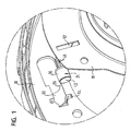
- Fig. 1
- eine perspektivische Ansicht eines Gasgeneratorträgers, eines Zündelements und einer Luftsackhalteplatte eines erfindungsgemäßen Luftsackmoduls;
- Fig. 2
- eine Querschnittsansicht eines Schaltmechanismus des Luftsackmoduls von
Fig. 1 mit nicht ausgelöstem Zündelement; - Fig. 3
- eine Querschnittsansicht des Schaltmechanismus von
Fig. 2 mit gezündetem Zündelement; - Fig. 4
- eine alternative Ausführungsform des Schaltmechanismus von
Fig. 2 ; - Fig. 5
- ein Klemmelement zur Lagerung des Zündelements des Schaltmechanismus von
Fig. 4 ; - Fig. 6
- eine perspektivische Ansicht eines Gasgeneratorträgers, eines Zündelements, eines Zündelementgehäuses und einer Luftsackhalteplatte eines Luftsackmodulsgemäß einer Variante, die nicht Gegenstand der Erfindung ist; und
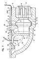
- Fig. 7
- eine Querschnittsansicht des in eine Aussparung des Gasgeneratorträgers eingesetzten Zündelements und Zündelementgehäuses von
Fig. 6 . - In
Fig. 1 ist ein erfindungsgemäßes Luftsackmodul dargestellt. Das Luftsackmodul umfasst einen Gasgeneratorträger 10, an dem ein Gasgenerator 12 zum Aufblasen eines Luftsacks 14 des Luftsackmoduls befestigbar ist. - Zur Anbringung des Luftsacks 14 an dem Gasgeneratorträger 10 ist eine Luftsackhalteplatte 16 vorgesehen, die so auf den Gasgeneratorträger 10 aufsetzbar und mit diesem verschraubbar ist, dass ein umlaufender Randabschnitt 18 des Luftsacks 14 zwischen dem Gasgeneratorträger 10 und der Luftsackhalteplatte 16 eingeklemmt wird. Im dargestellten Ausführungsbeispiel ist die Luftsackhalteplatte 16 Teil eines Gasgeneratorflansches. Alternativ ist es jedoch auch möglich, die Luftsackhalteplatte 16 als ein von einem Gasgeneratorflansch getrenntes Bauteil auszubilden.
- Der Luftsack 14 weist mindestens eine nicht gezeigte Abströmöffnung zur Entlüftung des Luftsacks 14 auf, durch welche - zusätzlich zu einer normalerweise ohnehin erfolgenden Abströmung des Luftsacks 14 - die Härte des aufgeblasenen Luftsacks 14 an einen zu schützenden Fahrzeuginsassen und/oder an die Stärke des zur Auslösung des Luftsackmoduls führenden Aufpralls anpassbar ist.
- Sofern keine zusätzliche Abströmung des Luftsacks 14 erforderlich ist, wird die Abströmöffnung durch ein Verschlusselement verschlossen gehalten, welches mit einem Halteband 22 verbunden ist oder zumindest in einem von der Abströmöffnung abgewandten Bereich als Halteband 22 ausgebildet ist. Das Halteband 22 ist im Bereich seines von der Abströmöffnung abgewandten Endes mittels eines Schaltmechanismus an dem Gasgeneratorträger 10 verankert. Bei Bedarf kann das Halteband 22 durch eine Betätigung des Schaltmechanismus von diesem losgelöst und zur Öffnung der Abströmöffnung freigegeben werden.
- Der Schaltmechanismus der ersten Luftsackmodulvariante ist durch ein pyrotechnisches Zündelement 24 gebildet, welches an einer von der Luftsackhalteplatte 16 abgewandten Unterseite 26 des Gasgeneratorträgers 10 angeordnet und so fixiert ist, dass es im Falle seiner Auslösung bewegt werden kann. Genauer gesagt ist das Zündelement 24 in einer zu der Unterseite 26 parallelen Richtung verschiebbar in einer Zündelementführung gelagert.
- Bei der in
Fig. 1 bis 3 dargestellten Ausführungsform ist die Führung durch ein einstückig mit dem Gasgeneratorträger 10 ausgebildetes Führungsgehäuse 28 gebildet, welches einen an die äußere Form des Zündelements 24 angepassten Aufnahmeraum 30 aufweist. Der Aufnahmeraum 30 ist an einer Vorderseite durch eine Prallwand 32 begrenzt und weist an einer der Prallwand 32 gegenüberliegenden Rückseite eine Ausstoßöffnung 34 auf. - Das Zündelement 24 umfasst einen zylindrischen Hauptabschnitt 36, an dessen Rückseite sich ein Anschlussabschnitt 38 mit elektrischen Kontakten 40 anschließt, welcher zur Verbindung des Zündelements 24 mit einer Zündelektronik dient. In dem Hauptabschnitt 36 des Zündelements 24 ist eine Zündladung untergebracht, die bei einer Zündung des Zündelements 24 eine vordere Stirnseite 42 des Zündelements 24 öffnet.
- Das Zündelement 24 ist so in den Aufnahmeraum 30 des Führungsgehäuses 28 eingesetzt, dass die vordere Stirnseite 42 der Prallwand 32 gegenüberliegt. In dem Gehäuse 28 ist im Bereich der Prallwand 32 eine Schulter 48 ausgebildet, an die der Hauptabschnitt 36 des Zündelements 24 anstoßen kann, um eine korrekte Positionierung des Zündelements 24 in dem Gehäuse 28 und insbesondere einen vorbestimmten Abstand zwischen der vorderen Stirnseite 42 des Zündelements 24 und der Prallwand 32 sicherzustellen. Durch die vorderen Stirnseite 42 des Zündelements 24 und die Prallwand 32 wird ein Druckraum 46 begrenzt, in welchem bei Auslösung des Zündelements 24 ein Gasdruck und/oder ein Rückstoß erzeugt werden bzw. wird.
- Am Gehäuse 28 können ferner Mittel vorgesehen sein, um im Bereich des Anschlussabschnitts 38 mit dem Zündelement 24 zusammenzuwirken und das Zündelement 24 in seiner korrekten Position zu sichern bzw. eine Bewegung des Zündelements 24 bei dessen Auslösung zuzulassen.
- Wie in
Fig. 2 gezeigt ist, ragt ein Endabschnitt 50 des Haltebands 22 quer zur Längserstreckung des Zündelements 24 in das Führungsgehäuse 28 hinein. In der Luftsackhalteplatte 16 und in dem Gasgeneratorträger 10 ist zu diesem Zweck jeweils eine schlitzförmige Durchgangsöffnung 52, 54 vorgesehen. - Der Endabschnitt 50 des Haltebands 22 weist eine Öffnung 56 auf, durch die sich der vordere Abschnitt 36 des Zündelements 24 nach Art eines Verriegelungsbolzens hindurch erstreckt. Auf diese Weise ist der Endabschnitt 50 des Haltebands 22 an dem Zündelement 24 und somit letztlich an dem Gasgeneratorträger 10 verankert.
- Bei einer Auslösung des Zündelements 24 bricht die entzündete Zündladung die vordere Stirnseite 42 des vorderen Zündelementabschnitts 36 auf, und es wird ein Gasdruck in dem Druckraum 46 erzeugt. Da der Druckraum 46 mit Ausnahme der vorderen Stirnseite 42 des Zündelements 24 ausschließlich von festen Wänden des Führungsgehäuses 28 begrenzt ist, wird das Zündelement 24 durch den erzeugten Rückstoß und/oder Gasdruck durch die Ausstoßöffnung 34 aus dem Führungsgehäuse 28 herausgeschoben.
- Dadurch werden der Endabschnitt 50 des Haltebands 22 und der vordere Abschnitt 36 des Zündelements 24 außer Eingriff gebracht. Das auf diese Weise von seiner Verankerung losgelöste und freigeschaltete Halteband 22 kann sich folglich aus dem Führungsgehäuse 28 herausbewegen und eine Öffnung der Abströmöffnung des Luftsacks 14 bewirken.
- Wie
Fig. 2 und 3 zeigen, ist in der Prallwand 32 ein sich etwa koaxial mit der Längsmittelachse 57 des in den Aufnahmeraum 30 eingesetzten Zündelements 24 erstreckender Entlüftungskanal 58 ausgebildet, welcher den Druckraum 46 mit der Umgebung des Führungsgehäuses 28 verbindet. Der Entlüftungskanal 58 ermöglicht einen Abbau des bei Zündung des Zündelements 24 in dem Druckraum 46 erzeugten Gasdrucks, wodurch eine kontrollierte Rückwärtsbewegung des Zündelements 24 aus dem Führungsgehäuse 28 heraus erreicht wird. - Um eine unkontrollierte Bewegung des Zündelements 24 nach dem Austritt aus dem Führungsgehäuse 28 zu verhindern, ist außerdem ein Anschlag 60 vorgesehen, welcher die Bewegung des vollständig aus dem Aufnahmeraum 30 herausgeschobenen Zündelements 24 parallel zur Unterseite 25 des Gasgeneratorträgers 10 begrenzt (
Fig. 3 ). Der Anschlag 60 ist durch einen an der Unterseite 26 des Gasgeneratorträgers 10 vorgesehenen und einstückig mit dem Gasgeneratorträger 10 ausgebildeten Vorsprung gebildet. - In
Fig. 4 ist eine alternative Ausführungsform der Zündelementführung dargestellt, die im Unterschied zur voranstehend beschriebenen Ausführungsform nicht durch ein einen Aufnahmeraum 30 für das Zündelement 24 begrenzendes Gehäuse 28, sondern durch eine Klemmvorrichtung gebildet ist, die mindestens zwei in Richtung der Längsmittelachse 57 des aufzunehmenden Zündelements 24 zueinander beabstandete Klemmelemente 62 umfasst. Dabei sind die Klemmelemente 62 so an der Unterseite 26 des Gasgeneratorträgers 10 angeordnet, dass sich der durch das Zündelement 24 zu fixierende Endabschnitt 50 des Haltebands 22 zwischen den Klemmelementen 62 hindurch erstreckt. - Wie in
Fig. 5 gezeigt ist, umfasst jedes Klemmelement 62 zwei an den Gasgeneratorträger 10 angeformte Klemmhälften 64, die zueinander beabstandet sind und an ihren zueinanderweisenden Innenseiten jeweils eine teilkreisförmige Aussparung 66 aufweisen, die zusammen einen Aufnahmeraum für das Zündelement 24 bilden. Zur Anbringung des Zündelements 24 an dem Gasgeneratorträger 10 braucht das Zündelement 24 lediglich in Richtung des Pfeils 68 von unten in die Klemmelemente 62 hineingedrückt zu werden. - Auch bei der in
Fig. 4 gezeigten Zündelementführung ist eine im Bereich der vorderen Stirnseite 42 des in der Führung 28 gehaltenen Zündelements 24 angeordnete Prallwand 32 vorgesehen. Wie bereits in Verbindung mitFig. 3 beschrieben wurde, wird die Prallwand 32 bei einer Zündung des Zündelements 24 mit Gas beaufschlagt, wodurch das Zündelement 24 in Richtung seiner Längsmittelachse 57 von der Prallwand 32 weg aus den Klemmelementen 62 herausgeschoben und der Endabschnitt 50 des Haltebands 22 zur Öffnung der Abströmöffnung des Luftsacks 14 freigegeben wird. - Die Prallwand 32 der in
Fig. 4 gezeigten Ausführungsform weist keinen Entlüftungskanal auf. Stattdessen stellt sich die gewünschte Stärke des bei Zündung des Zündelements 24 erzeugten Gasdrucks dadurch ein, dass das durch das Zündelement 24 freigesetzte Gas aus dem Zwischenraum zwischen der Prallwand 32 und der vorderen Stirnseite 42 des Zündelements bzw. dem der Prallwand 32 gegenüberliegenden Klemmelement 62 frei entweichen kann. - Wie
Fig. 2 und 3 zeigen, ist der Schaltmechanismus zur Freigabe des Haltebands 22 unterhalb der Luftsackhalteplatte 16 und somit vergleichsweise nahe an dem Gasgenerator 12 angeordnet. Das Halteband 22 erstreckt sich folglich aus dem Inneren des Luftsacks 14 durch die Luftsackhalteplatte 16 und den Gasgeneratorträger 10 hindurch, um durch das Zündelement 24 fixiert zu werden. - Grundsätzlich ist es aber auch möglich, den Schaltmechanismus weiter von dem Gasgenerator 12 entfernt, in
Fig. 2 und 3 also weiter rechts, und insbesondere - in Richtung der Haupterstreckung des Gasgeneratorträgers 10 gesehen - mit einem Abstand zu Luftsackhalteplatte 16 vorzusehen. In diesem Fall kann das Halteband 22 nicht direkt aus dem Inneren des Luftsacks 14 durch den Gasgeneratorträger 10 hindurch zu dem Schaltmechanismus geführt werden, sondern es muss zunächst durch eine zusätzliche Öffnung in dem Luftsack 14 aus diesem heraus geführt werden, um dann mit dem Schaltmechanismus in Eingriff gebracht zu werden. - In
Fig. 6 und7 ist ein Luftsackmodul gemäß einer von der Erfindung nicht umfassten zweiten Variante dargestellt, welche sich von der voranstehend beschriebenen erfindungsgemäßen ersten Luftsackmodulvariante im Wesentlichen in der Ausbildung des Schaltmechanismus zur Fixierung bzw. Freigabe des Haltebands 22 unterscheidet. Gleichartige bzw. gleichwirkende Bauteile der zweiten Luftsackmodulvariante sind deshalb mit den gleichen Bezugszeichen versehen, wie sie bereits bei der ersten Luftsackmodulvariante verwendet wurden. - Ähnlich wie die erste Luftsackmodulvariante umfasst auch die zweite Luftsackmodulvariante einen Gasgeneratorträger 10 und eine Luftsackhalteplatte 16 zur Befestigung eines Luftsacks 14 an dem Gasgeneratorträger 10 derart, dass ein Randabschnitt 18 des Luftsacks 14 zwischen dem Gasgeneratorträger 10 und der Luftsackhalteplatte 16 eingeklemmt wird (
Fig. 7 ). Zum Verschließen bzw. Öffnen einer Abströmöffnung des Luftsacks 14 ist auch hier ein Verschlusselement vorgesehen, welches mit einem Halteband 22 verbunden ist oder zumindest in einem von der Abströmöffnung abgewandten Bereich als Halteband 22 ausgebildet ist. - Im Unterschied zur ersten Luftsackmodulvariante umfasst der Schaltmechanismus der zweiten Luftsackmodulvariante ein Zündelement 24, das in einem Zündelementgehäuse 70 untergebracht ist, welches seinerseits in eine Aussparung 72 des Gasgeneratorträgers 10 eingesetzt ist.
- Wie bei der ersten Luftsackmodulvariante weist das Zündelement 24 einen zylindrischen Hauptabschnitt 36 auf, in welchem eine Zündladung untergebracht ist, die bei einer Zündung des Zündelements 24 eine vordere Stirnseite 42 des Zündelements 24 öffnet. Ferner ist auch bei diesem Zündelement 24 ein Anschlussabschnitt 38 mit elektrischen Kontakten 40 zur Verbindung des Zündelements 24 mit einer Zündschaltung an der Rückseite des Hauptabschnitts 36 vorgesehen. Im Unterschied zur ersten Luftsackmodulvariante ist der Hauptabschnitt 36 jedoch von einer ringförmig umlaufenden Verbreiterung 74 umgeben.
- Das Zündelementgehäuse 70 ist an einer Unterseite offen, damit das Zündelement 24 in das Zündelementgehäuse 70 eingebracht werden kann.
- Eine einen Aufnahmeraum für das Zündelement 24 begrenzende innere Oberfläche 76 des Zündelementgehäuses 70 ist zumindest bereichsweise an die äußere Gestalt des Zündelements 24 angepasst, so dass das in das Zündelementgehäuse 70 eingesetzte Zündelement 24 gegen eine Bewegung des Zündelements 24 in Richtung der Längsmittelachse 57 des Zündelements 24 gesichert ist. Insbesondere weist das Zündelementgehäuse 70 an seiner Innenseite eine Ringnut 78 auf, deren Profil an das Profil der ringförmigen Verbreiterung 74 des Zündelements 24 angepasst ist. Somit wird zumindest bereichsweise ein Formschluss zwischen dem Zündelementgehäuse 70 und dem in das Zündelementgehäuse 70 eingesetzten Zündelement 24 erreicht.
- An die offene Unterseite angrenzende, gegenüberliegende Außenseiten 80 des Zündelementgehäuses 70 weisen jeweils zwei sich quer zur Längsrichtung des eingesetzten Zündelements 24 erstreckende Vorsprünge 82 auf, die unter Bildung einer entsprechenden Vertiefung 84 zueinander beabstandet sind.
- Entsprechend sind an gegenüberliegenden Innenseiten der Aussparung 72 des Gasgeneratorträgers 10 zu den Vertiefungen 84 des Zündelementgehäuses 70 komplementär ausgebildete Vorsprünge 86 vorgesehen, welche in die Vertiefungen 84 des in die Aussparung 72 eingesetzten Zündelementgehäuses 70 eingreifen und das Zündelementgehäuse 70 in der Aussparung 72 fixieren und insbesondere an einer Relativbewegung bezüglich des Gasgeneratorträgers 10 in einer zur Längsmittelachse 57 des eingesetzten Zündelements 24 parallelen Richtung hindern.
- Gleichzeitig weist auch die Aussparung 72 eine ringnutartige Vertiefung 88 auf, deren Profil an das Profil der ringförmigen Verbreiterung 74 des Zündelements 24 angepasst ist und die so positioniert ist, dass die Verbreiterung 74 des zusammen mit dem Zündelementgehäuse 70 in die Aussparung 72 eingesetzten Zündelements 24 in die Vertiefung 88 eingreift.
- Durch das Zusammenspiel der ringförmigen Verbreiterung 74 des Zündelements 24, der Vorsprünge 82, 86 des Zündelementgehäuses 70 bzw. der Aussparung 72, und der Vertiefungen 78, 84, 88 des Zündelementgehäuses 70 bzw. der Aussparung 72 ist zum einen das Zündelementgehäuse 70 in der Aussparung 72 und zum anderen das Zündelement 24 in dem Zündelementgehäuse 70 sowie in der Aussparung 72 fixiert und insbesondere an einer Relativbewegung bezüglich des Gasgeneratorträgers 10 in einer zur Längsmittelachse 57 des Zündelements 24 parallelen Richtung gehindert.
- Zur Fixierung des Haltebands 22 weist das Zündelementgehäuse 70 einen Haken 90 auf, welcher verschwenkbar an dem das Zündelement 24 umgebenden Teil des Zündelementgehäuses 70 angelenkt ist (
Fig. 7 ). - Der Haken 90 umfasst einen parallel zur Längsmittelachse 57 des Zündelements 24 orientierten und sich durch eine im Endabschnitt 50 des Haltebands 22 befindliche Öffnung 56 hindurch erstreckenden Halteabschnitt 92 sowie einen quer zur Längsmittelachse 57 des Zündelements 24 orientierten und der sich bei Zündung des Zündelements 24 öffnenden vorderen Stirnseite 42 des Zündelements 24 vorgelagerten Prallabschnitt 94.
- Die Anbindung des Hakens 90 an den übrigen Teil des Zündelementgehäuses 70 erfolgt mittels eines gebogenen Stegabschnitts 96, welcher ausgehend von einer Oberseite 97 des Zündelementgehäuses 70 in einen Übergangsbereich zwischen Halteabschnitt 92 und Prallabschnitt 94 übergeht.
- Die Krümmung des Stegabschnitts 96 ist so gewählt, dass sich der Haken 94 nur unter Überwindung einer Rückstellkraft des Stegabschnitts 96 nach oben verschwenken lässt. Zur Verbesserung der Verschwenkbarkeit ist an der Oberseite des Übergangsbereichs vom Stegabschnitt 96 zum Haken 90 eine parallel zur Sollschwenkachse verlaufende Einkerbung 98 vorgesehen, welche zu einer filmscharnierartigen Verjüngung des Stegabschnitts 96 führt.
- Um den Haken 90 zusätzlich vor einer unbeabsichtigten Verschwenkung und somit Freigabe des fixierten Haltebands 22 zu sichern, ist eine Sicherungszunge 100 der Luftsackhalteplatte 16 vorgesehen, die sich in eine Durchgangsöffnung 52 der Luftsackhalteplatte 16 für das Halteband 22 hinein erstreckt. Wie
Fig. 7 zeigt, ist die Sicherungszunge 100 in Form eines nach oben offenen V derart gebogen, dass sie im Bereich ihres freien Endes von oben an dem freien Ende des Halteabschnitts 92 des Hakens 90 anliegt. Die Sicherungszunge 100 ist so ausgebildet, dass bei Auslösung des Zündelements 24 der Haken 90 die Sicherungszunge 100 wegdrücken kann und/oder das freie Ende des Halteabschnitts 92 umgebogen wird, um das Halteband 22 freizugeben. - Bei Zündung des Zündelements 24 wird der vor dem Zündelement 24 befindliche Prallabschnitt 94 des Hakens 90 durch den durch das Zündelement 24 erzeugten Gasdruck beaufschlagt. Dadurch wird der Haken 90 entgegen der Rückstellkraft des Steckabschnitts 96 und unter Überwindung der Sicherungszunge 100 von dem Zündelement 24 weggedrückt und, in
Fig. 7 nach oben, geschwenkt. - Das freie Ende des Prallabschnitts 94 folgt dabei dem Verlauf einer teilkreisförmig gekrümmten Oberfläche 102 der Aussparung 72, welche zusammen mit dem Prallabschnitt 94 und dem Zündelement 24 einen Druckraum 104 begrenzt.
- Die durch das Zündelement 24 freigesetzte Energie wird somit zur Verschwenkung des Hakens 90 genutzt. Dies ermöglicht eine schnelle Freigabe des Haltebands 22, welches sich von dem Haken 90 lösen kann, sobald der Halteabschnitt 92 die Sicherungszunge 100 überwunden hat.
- Zur Befestigung des Zündelementgehäuses 70 an der Luftsackhalteplatte 16 ist ein Steckclip 106 an der Oberseite 97 des Zündelementgehäuses 70 vorgesehen, welcher in eine entsprechend ausgebildete Stecköffnung 108 der Luftsackhalteplatte 16 einsteckbar ist.
- Um das Zündelementgehäuse 70 zusätzlich an der Luftsackhalteplatte 16 zu sichern, sind in einem von dem Haken 90 abgewandten Bereich des Zündelementgehäuses 70 außerdem zwei Rasthaken 110 an dem Zündelementgehäuse 70 ausgebildet, die in entsprechenden Rastöffnungen 112 der Luftsackhalteplatte 16 einrasten können.
- Auf diese Weise lässt sich bei der Montage des Luftsackmodulgehäuses zunächst das Halteband 22 mit dem Haken 90 des Zündelementgehäuses 70 in Eingriff bringen und danach das Zündelementgehäuse 70 an der Luftsackhalteplatte 16 befestigen. Anschließend kann das Zündelement 24 in das Zündelementgehäuse 70 oder in die Aussparung 72 des Gasgeneratorträgers 10 eingesetzt und die Luftsackhalteplatte 16 zusammen mit dem Zündelementgehäuse 70 an dem Gasgeneratorträger 10 befestigt werden.
- Bis zum endgültigen Zusammenfügen von Luftsackhalteplatte 16 und Gasgeneratorträger 10 ist also eine optische Kontrolle darüber möglich, ob das Halteband 22 sicher mit dem Schaltmechanismus verbunden ist.
-
- 10
- Gasgeneratorträger
- 12
- Gasgenerator
- 14
- Luftsack
- 16
- Luftsackhalteplatte
- 18
- Randabschnitt
- 22
- Halteband
- 24
- Zündelement
- 26
- Unterseite
- 28
- Führungsgehäuse
- 30
- Aufnahmeraum
- 32
- Prallwand
- 34
- Ausstoßöffnung
- 36
- Hauptabschnitt
- 38
- Anschlussabschnitt
- 40
- elektrischer Kontakt
- 42
- vordere Stirnseite
- 46
- Druckraum
- 48
- Schulter
- 50
- Endabschnitt
- 52
- Durchgangsöffnung
- 54
- Durchgangsöffnung
- 56
- Öffnung
- 57
- Längsmittelachse
- 58
- Entlüftungskanal
- 60
- Anschlag
- 62
- Klemmelement
- 64
- Klemmhälfte
- 66
- Aussparung
- 68
- Pfeil
- 70
- Zündelementgehäuse
- 72
- Aussparung
- 74
- Verbreiterung
- 76
- innere Oberfläche
- 78
- Ringnut
- 80
- Außenseite
- 82
- Vorsprung
- 84
- Vertiefung
- 86
- Vorsprung
- 88
- Vertiefung
- 90
- Haken
- 92
- Halteabschnitt
- 94
- Prallabschnitt
- 96
- Stegabschnitt
- 97
- Oberseite
- 98
- Einkerbung
- 100
- Sicherungszunge
- 102
- gekrümmte Oberfläche
- 104
- Druckraum
- 106
- Steckclip
- 108
- Stecköffnung
- 110
- Rasthaken
- 112
- Rastöffnung
Claims (7)
- Luftsackmodul für ein Kraftfahrzeug mit einem mindestens eine Abströmöffnung aufweisenden aufblasbaren Luftsack (14), einem Verschlusselement (22) zum Verschließen der Abströmöffnung und einem ein pyrotechnisches Zündelement (24) umfassenden Schaltmechanismus, wobei das Verschlusselement (22) durch den Schaltmechanismus in einer die Abströmöffnung verschließenden Lage gehalten und durch eine Auslösung des Zündelements (24) zur Öffnung der Abströmöffnung mit dem Schaltmechanismus außer Eingriff bringbar ist,
dadurch gekennzeichnet,
dass das Verschlusselement (22) in seiner die Abströmöffnung verschließenden Lage mit dem Zündelement (24) in Eingriff steht und das Zündelement (24) derart angeordnet ist, dass es sich bei seiner Auslösung relativ zum Verschlusselement (22) bewegen kann, um das Verschlusselement (22) freizugeben. - Luftsackmodul nach Anspruch 1,
dadurch gekennzeichnet,
dass das Zündelement (24) bezüglich des Verschlusselements (22) verschiebbar ist. - Luftsackmodul nach Anspruch 1 oder 2,
dadurch gekennzeichnet,
dass sich ein Abschnitt (36) des Zündelements zum Halten des Verschlusselements (22) durch eine Öffnung (56) des Verschlusselements (22) hindurch erstreckt. - Luftsackmodul nach einem der vorherigen Ansprüche,
dadurch gekennzeichnet,
dass das Zündelement (24) mittels einer Klemmvorrichtung (62, 64) an einem Träger (10) für einen Gasgenerator (12) zum Aufblasen des Luftsacks (14) gelagert ist. - Luftsackmodul nach einem der vorherigen Ansprüche,
dadurch gekennzeichnet,
dass eine Prallwand (32) im Bereich einer sich bei Auslösung des Zündelements (24) öffnenden Stirnseite (42) des Zündelements (24) vorgesehen ist. - Luftsackmodul nach Anspruch 5,
dadurch gekennzeichnet,
dass ein Entlüftungskanal (58) in der Prallwand (32) vorgesehen ist, durch den ein Gasdruck reduzierbar ist, welcher bei Auslösung des Zündelements (24) zwischen dem Zündelement (24) und der Prallwand (32) aufgebaut wird. - Luftsackmodul nach einem der vorherigen Ansprüche,
dadurch gekennzeichnet,
dass ein Anschlag (60) vorgesehen ist, um die zur Freigabe des Verschlusselements (22) erfolgende Bewegung des Zündelements (24) zu begrenzen.
Priority Applications (6)
| Application Number | Priority Date | Filing Date | Title |
|---|---|---|---|
| EP05021332A EP1769978B1 (de) | 2005-09-29 | 2005-09-29 | Luftsackmodul mit Abströmöffnung |
| AT06008946T ATE387346T1 (de) | 2005-09-29 | 2005-09-29 | Luftsackmodul mit abströmöffnung |
| DE502005003011T DE502005003011D1 (de) | 2005-09-29 | 2005-09-29 | Luftsackmodul mit Abströmöffnung |
| AT05021332T ATE387345T1 (de) | 2005-09-29 | 2005-09-29 | Luftsackmodul mit abströmöffnung |
| DE502005003016T DE502005003016D1 (de) | 2005-09-29 | 2005-09-29 | Luftsackmodul mit Abströmöffnung |
| EP06008946A EP1772323B1 (de) | 2005-09-29 | 2005-09-29 | Luftsackmodul mit Abströmöffnung |
Applications Claiming Priority (1)
| Application Number | Priority Date | Filing Date | Title |
|---|---|---|---|
| EP05021332A EP1769978B1 (de) | 2005-09-29 | 2005-09-29 | Luftsackmodul mit Abströmöffnung |
Related Child Applications (1)
| Application Number | Title | Priority Date | Filing Date |
|---|---|---|---|
| EP06008946A Division EP1772323B1 (de) | 2005-09-29 | 2005-09-29 | Luftsackmodul mit Abströmöffnung |
Publications (2)
| Publication Number | Publication Date |
|---|---|
| EP1769978A1 EP1769978A1 (de) | 2007-04-04 |
| EP1769978B1 true EP1769978B1 (de) | 2008-02-27 |
Family
ID=35709147
Family Applications (2)
| Application Number | Title | Priority Date | Filing Date |
|---|---|---|---|
| EP06008946A Expired - Lifetime EP1772323B1 (de) | 2005-09-29 | 2005-09-29 | Luftsackmodul mit Abströmöffnung |
| EP05021332A Expired - Lifetime EP1769978B1 (de) | 2005-09-29 | 2005-09-29 | Luftsackmodul mit Abströmöffnung |
Family Applications Before (1)
| Application Number | Title | Priority Date | Filing Date |
|---|---|---|---|
| EP06008946A Expired - Lifetime EP1772323B1 (de) | 2005-09-29 | 2005-09-29 | Luftsackmodul mit Abströmöffnung |
Country Status (3)
| Country | Link |
|---|---|
| EP (2) | EP1772323B1 (de) |
| AT (2) | ATE387346T1 (de) |
| DE (2) | DE502005003011D1 (de) |
Cited By (1)
| Publication number | Priority date | Publication date | Assignee | Title |
|---|---|---|---|---|
| KR20220107263A (ko) * | 2019-12-05 | 2022-08-02 | 오토리브 에이에스피, 인크. | 자동차용 안전 장치를 위한 액추에이터 장치 및 조립체 |
Families Citing this family (17)
| Publication number | Priority date | Publication date | Assignee | Title |
|---|---|---|---|---|
| US7938444B2 (en) | 2008-10-14 | 2011-05-10 | Autoliv Asp, Inc. | Mounting bracket for tether release mechanism |
| DE102009005771B4 (de) * | 2009-01-23 | 2026-02-26 | Trw Airbag Systems Gmbh | Aktuatorbaugruppe, Gassackmodul mit einer solchen Aktuatorbaugruppe sowie Verfahren zur Montage eines Zugbands an einem Gassackmodul mittels einer Aktuatorbaugruppe |
| DE102009055266A1 (de) * | 2009-12-23 | 2011-06-30 | Takata-Petri Ag, 63743 | Airbagmodul für ein Kraftfahrzeug |
| DE102010039895A1 (de) | 2010-06-15 | 2011-12-15 | Takata-Petri Ag | Airbagmodul für ein Kraftfahrzeug |
| DE102011014869B4 (de) * | 2011-03-23 | 2015-05-07 | Autoliv Development Ab | Befestigungsvorrichtung zur lösbaren Befestigung eines Elements an einem fahrzeugfesten Bauteil |
| US8408585B2 (en) * | 2011-03-23 | 2013-04-02 | Autoliv Asp, Inc. | Pyrotechnic tether release assembly for inflatable airbags |
| DE102015219300B3 (de) * | 2015-10-06 | 2017-04-06 | Volkswagen Aktiengesellschaft | Befestigungsanordnung zur Befestigung eines Gasgenerators |
| US9776594B2 (en) | 2015-12-04 | 2017-10-03 | Autoliv Asp, Inc. | Airbag tether release assemblies |
| US10336285B2 (en) | 2016-09-07 | 2019-07-02 | Joyson Safety Systems Acquisition Llc | Airbag module with active vent rotation countermeasure |
| DE102017108176A1 (de) | 2017-04-18 | 2018-10-18 | Autoliv Development Ab | Airbagmodul mit Bremsvorrichtung für pyrotechnisch angetriebenen Aktuator |
| DE102019112432B4 (de) * | 2019-05-13 | 2023-11-30 | Mann+Hummel Gmbh | Entgasungseinheit und Elektronikgehäuse, insbesondere Batteriegehäuse |
| DE102019122379B4 (de) | 2019-08-20 | 2022-05-05 | Autoliv Development Ab | Airbagmodul |
| US11180107B2 (en) | 2019-12-05 | 2021-11-23 | Autoliv Asp, Inc. | Tether release for an automotive safety device |
| US11613227B2 (en) * | 2021-07-15 | 2023-03-28 | ZF Passive Safety Systems US Inc. | Tether actuation unit for airbag module |
| JP7552574B2 (ja) * | 2021-12-17 | 2024-09-18 | 豊田合成株式会社 | エアバッグ装置 |
| JP7816237B2 (ja) * | 2023-03-17 | 2026-02-18 | 豊田合成株式会社 | 発熱構造体および発熱組付体 |
| JP2024132710A (ja) * | 2023-03-17 | 2024-10-01 | 豊田合成株式会社 | 発熱装置用キャップ、発熱構造体およびエアバッグ装置 |
Family Cites Families (4)
| Publication number | Priority date | Publication date | Assignee | Title |
|---|---|---|---|---|
| US6899134B2 (en) * | 2001-10-23 | 2005-05-31 | Automotive Technologies International, Inc. | Discharge valves for airbags and airbags including the same |
| US6648371B2 (en) * | 2001-07-12 | 2003-11-18 | Delphi Technologies, Inc. | Variable venting air bag assembly |
| US6832778B2 (en) * | 2002-07-19 | 2004-12-21 | Delphi Technologies, Inc. | Air bag restraint including selectively operable venting elements |
| US7144037B2 (en) * | 2003-03-06 | 2006-12-05 | Autoliv Development Ab | Safety device |
-
2005
- 2005-09-29 AT AT06008946T patent/ATE387346T1/de not_active IP Right Cessation
- 2005-09-29 DE DE502005003011T patent/DE502005003011D1/de not_active Expired - Lifetime
- 2005-09-29 AT AT05021332T patent/ATE387345T1/de not_active IP Right Cessation
- 2005-09-29 EP EP06008946A patent/EP1772323B1/de not_active Expired - Lifetime
- 2005-09-29 DE DE502005003016T patent/DE502005003016D1/de not_active Expired - Lifetime
- 2005-09-29 EP EP05021332A patent/EP1769978B1/de not_active Expired - Lifetime
Cited By (1)
| Publication number | Priority date | Publication date | Assignee | Title |
|---|---|---|---|---|
| KR20220107263A (ko) * | 2019-12-05 | 2022-08-02 | 오토리브 에이에스피, 인크. | 자동차용 안전 장치를 위한 액추에이터 장치 및 조립체 |
Also Published As
| Publication number | Publication date |
|---|---|
| EP1772323A1 (de) | 2007-04-11 |
| EP1772323B1 (de) | 2008-02-27 |
| DE502005003016D1 (de) | 2008-04-10 |
| ATE387346T1 (de) | 2008-03-15 |
| DE502005003011D1 (de) | 2008-04-10 |
| EP1769978A1 (de) | 2007-04-04 |
| ATE387345T1 (de) | 2008-03-15 |
Similar Documents
| Publication | Publication Date | Title |
|---|---|---|
| EP2287047B1 (de) | Gassackmodul | |
| EP1772323B1 (de) | Luftsackmodul mit Abströmöffnung | |
| DE102005012614B4 (de) | Airbag-System | |
| DE102009005771B4 (de) | Aktuatorbaugruppe, Gassackmodul mit einer solchen Aktuatorbaugruppe sowie Verfahren zur Montage eines Zugbands an einem Gassackmodul mittels einer Aktuatorbaugruppe | |
| WO2000037286A2 (de) | Verkleidungsmodul mit airbag | |
| DE102009031120B4 (de) | Airbageinrichtung für ein Kraftfahrzeug | |
| WO2019141676A1 (de) | Auslösbare haltevorrichtung für ein fangband eines gassacks und gehäuse für einen gassack | |
| DE102012023877A1 (de) | Pyrotechnische aktuatorbaugruppe sowie gassackmodul mit einer solchen aktuatorbaugruppe | |
| DE102013000142A1 (de) | Gassackeinheit | |
| EP2958776B1 (de) | Airbagmodul für ein kraftfahrzeug | |
| WO2017216348A1 (de) | Lenksäule für ein kraftfahrzeug | |
| DE102012007406A1 (de) | Airbageinrichtung | |
| WO2012022416A1 (de) | Schocksicherer schnellverschluss für einen endbeschlag eines sicherheitsgurtes | |
| DE102008006905B4 (de) | Airbaganordnung für ein Kraftfahrzeug | |
| EP2516216A1 (de) | Airbagmodul für ein kraftfahrzeug | |
| DE102021118823A1 (de) | Schutzeinrichtung für einen Kopfairbag eines Kraftwagens | |
| DE10103245C1 (de) | Überrollschutzsystem für Kraftfahrzeuge | |
| DE102017219689B4 (de) | Sicherheitseinrichtung eines Kraftfahrzeuges | |
| DE102017102029B4 (de) | Sperranordnung für ein staufach eines kraftfahrzeugs | |
| DE10103249C1 (de) | Überrollschutzsystem für Kraftfahrzeuge | |
| DE102019122379B4 (de) | Airbagmodul | |
| DE102009038442B4 (de) | Airbageinrichtung mit einem kraftfahrzeugseitigen Tragteil, einem Gasgeneratormodul und einem Gassackmodul | |
| DE102005002393B3 (de) | Fahrzeuginsassen-Schutzvorrichtung mit Sicherheitsgurtanordnung und ventilationsgesteuertem Seitenairbag | |
| EP1671850A2 (de) | Gassackmodul | |
| DE102016001142A1 (de) | Verfahren zur Montage einer Aktuatorbaugruppe sowie Gassackmodul mit einer montierten Aktuatorbaugruppe |
Legal Events
| Date | Code | Title | Description |
|---|---|---|---|
| PUAI | Public reference made under article 153(3) epc to a published international application that has entered the european phase |
Free format text: ORIGINAL CODE: 0009012 |
|
| 17P | Request for examination filed |
Effective date: 20060427 |
|
| AK | Designated contracting states |
Kind code of ref document: A1 Designated state(s): AT BE BG CH CY CZ DE DK EE ES FI FR GB GR HU IE IS IT LI LT LU LV MC NL PL PT RO SE SI SK TR |
|
| AX | Request for extension of the european patent |
Extension state: AL BA HR MK YU |
|
| GRAP | Despatch of communication of intention to grant a patent |
Free format text: ORIGINAL CODE: EPIDOSNIGR1 |
|
| AKX | Designation fees paid |
Designated state(s): AT BE BG CH CY CZ DE DK EE ES FI FR GB GR HU IE IS IT LI LT LU LV MC NL PL PT RO SE SI SK TR |
|
| GRAS | Grant fee paid |
Free format text: ORIGINAL CODE: EPIDOSNIGR3 |
|
| GRAA | (expected) grant |
Free format text: ORIGINAL CODE: 0009210 |
|
| AK | Designated contracting states |
Kind code of ref document: B1 Designated state(s): AT BE BG CH CY CZ DE DK EE ES FI FR GB GR HU IE IS IT LI LT LU LV MC NL PL PT RO SE SI SK TR |
|
| REG | Reference to a national code |
Ref country code: GB Ref legal event code: FG4D Free format text: NOT ENGLISH |
|
| REG | Reference to a national code |
Ref country code: CH Ref legal event code: EP |
|
| REG | Reference to a national code |
Ref country code: IE Ref legal event code: FG4D Free format text: LANGUAGE OF EP DOCUMENT: GERMAN |
|
| REF | Corresponds to: |
Ref document number: 502005003011 Country of ref document: DE Date of ref document: 20080410 Kind code of ref document: P |
|
| PG25 | Lapsed in a contracting state [announced via postgrant information from national office to epo] |
Ref country code: ES Free format text: LAPSE BECAUSE OF FAILURE TO SUBMIT A TRANSLATION OF THE DESCRIPTION OR TO PAY THE FEE WITHIN THE PRESCRIBED TIME-LIMIT Effective date: 20080607 Ref country code: FI Free format text: LAPSE BECAUSE OF FAILURE TO SUBMIT A TRANSLATION OF THE DESCRIPTION OR TO PAY THE FEE WITHIN THE PRESCRIBED TIME-LIMIT Effective date: 20080227 Ref country code: IS Free format text: LAPSE BECAUSE OF FAILURE TO SUBMIT A TRANSLATION OF THE DESCRIPTION OR TO PAY THE FEE WITHIN THE PRESCRIBED TIME-LIMIT Effective date: 20080627 |
|
| NLV1 | Nl: lapsed or annulled due to failure to fulfill the requirements of art. 29p and 29m of the patents act | ||
| ET | Fr: translation filed | ||
| PG25 | Lapsed in a contracting state [announced via postgrant information from national office to epo] |
Ref country code: LV Free format text: LAPSE BECAUSE OF FAILURE TO SUBMIT A TRANSLATION OF THE DESCRIPTION OR TO PAY THE FEE WITHIN THE PRESCRIBED TIME-LIMIT Effective date: 20080227 Ref country code: SI Free format text: LAPSE BECAUSE OF FAILURE TO SUBMIT A TRANSLATION OF THE DESCRIPTION OR TO PAY THE FEE WITHIN THE PRESCRIBED TIME-LIMIT Effective date: 20080227 Ref country code: PL Free format text: LAPSE BECAUSE OF FAILURE TO SUBMIT A TRANSLATION OF THE DESCRIPTION OR TO PAY THE FEE WITHIN THE PRESCRIBED TIME-LIMIT Effective date: 20080227 |
|
| REG | Reference to a national code |
Ref country code: IE Ref legal event code: FD4D |
|
| PG25 | Lapsed in a contracting state [announced via postgrant information from national office to epo] |
Ref country code: NL Free format text: LAPSE BECAUSE OF FAILURE TO SUBMIT A TRANSLATION OF THE DESCRIPTION OR TO PAY THE FEE WITHIN THE PRESCRIBED TIME-LIMIT Effective date: 20080227 Ref country code: DK Free format text: LAPSE BECAUSE OF FAILURE TO SUBMIT A TRANSLATION OF THE DESCRIPTION OR TO PAY THE FEE WITHIN THE PRESCRIBED TIME-LIMIT Effective date: 20080227 Ref country code: CZ Free format text: LAPSE BECAUSE OF FAILURE TO SUBMIT A TRANSLATION OF THE DESCRIPTION OR TO PAY THE FEE WITHIN THE PRESCRIBED TIME-LIMIT Effective date: 20080227 Ref country code: PT Free format text: LAPSE BECAUSE OF FAILURE TO SUBMIT A TRANSLATION OF THE DESCRIPTION OR TO PAY THE FEE WITHIN THE PRESCRIBED TIME-LIMIT Effective date: 20080721 Ref country code: SK Free format text: LAPSE BECAUSE OF FAILURE TO SUBMIT A TRANSLATION OF THE DESCRIPTION OR TO PAY THE FEE WITHIN THE PRESCRIBED TIME-LIMIT Effective date: 20080227 Ref country code: SE Free format text: LAPSE BECAUSE OF FAILURE TO SUBMIT A TRANSLATION OF THE DESCRIPTION OR TO PAY THE FEE WITHIN THE PRESCRIBED TIME-LIMIT Effective date: 20080527 Ref country code: IE Free format text: LAPSE BECAUSE OF FAILURE TO SUBMIT A TRANSLATION OF THE DESCRIPTION OR TO PAY THE FEE WITHIN THE PRESCRIBED TIME-LIMIT Effective date: 20080227 |
|
| PG25 | Lapsed in a contracting state [announced via postgrant information from national office to epo] |
Ref country code: RO Free format text: LAPSE BECAUSE OF FAILURE TO SUBMIT A TRANSLATION OF THE DESCRIPTION OR TO PAY THE FEE WITHIN THE PRESCRIBED TIME-LIMIT Effective date: 20080227 |
|
| PLBE | No opposition filed within time limit |
Free format text: ORIGINAL CODE: 0009261 |
|
| STAA | Information on the status of an ep patent application or granted ep patent |
Free format text: STATUS: NO OPPOSITION FILED WITHIN TIME LIMIT |
|
| PG25 | Lapsed in a contracting state [announced via postgrant information from national office to epo] |
Ref country code: LT Free format text: LAPSE BECAUSE OF FAILURE TO SUBMIT A TRANSLATION OF THE DESCRIPTION OR TO PAY THE FEE WITHIN THE PRESCRIBED TIME-LIMIT Effective date: 20080227 |
|
| 26N | No opposition filed |
Effective date: 20081128 |
|
| BERE | Be: lapsed |
Owner name: DELPHI TECHNOLOGIES, INC. Effective date: 20080930 |
|
| PG25 | Lapsed in a contracting state [announced via postgrant information from national office to epo] |
Ref country code: EE Free format text: LAPSE BECAUSE OF FAILURE TO SUBMIT A TRANSLATION OF THE DESCRIPTION OR TO PAY THE FEE WITHIN THE PRESCRIBED TIME-LIMIT Effective date: 20080227 Ref country code: BG Free format text: LAPSE BECAUSE OF FAILURE TO SUBMIT A TRANSLATION OF THE DESCRIPTION OR TO PAY THE FEE WITHIN THE PRESCRIBED TIME-LIMIT Effective date: 20080527 Ref country code: MC Free format text: LAPSE BECAUSE OF NON-PAYMENT OF DUE FEES Effective date: 20080930 |
|
| PG25 | Lapsed in a contracting state [announced via postgrant information from national office to epo] |
Ref country code: BE Free format text: LAPSE BECAUSE OF NON-PAYMENT OF DUE FEES Effective date: 20080930 Ref country code: CY Free format text: LAPSE BECAUSE OF FAILURE TO SUBMIT A TRANSLATION OF THE DESCRIPTION OR TO PAY THE FEE WITHIN THE PRESCRIBED TIME-LIMIT Effective date: 20080227 |
|
| PG25 | Lapsed in a contracting state [announced via postgrant information from national office to epo] |
Ref country code: AT Free format text: LAPSE BECAUSE OF NON-PAYMENT OF DUE FEES Effective date: 20080929 |
|
| REG | Reference to a national code |
Ref country code: CH Ref legal event code: PL |
|
| GBPC | Gb: european patent ceased through non-payment of renewal fee |
Effective date: 20090929 |
|
| PG25 | Lapsed in a contracting state [announced via postgrant information from national office to epo] |
Ref country code: LU Free format text: LAPSE BECAUSE OF NON-PAYMENT OF DUE FEES Effective date: 20080929 Ref country code: HU Free format text: LAPSE BECAUSE OF FAILURE TO SUBMIT A TRANSLATION OF THE DESCRIPTION OR TO PAY THE FEE WITHIN THE PRESCRIBED TIME-LIMIT Effective date: 20080828 |
|
| PG25 | Lapsed in a contracting state [announced via postgrant information from national office to epo] |
Ref country code: TR Free format text: LAPSE BECAUSE OF FAILURE TO SUBMIT A TRANSLATION OF THE DESCRIPTION OR TO PAY THE FEE WITHIN THE PRESCRIBED TIME-LIMIT Effective date: 20080227 |
|
| PG25 | Lapsed in a contracting state [announced via postgrant information from national office to epo] |
Ref country code: LI Free format text: LAPSE BECAUSE OF NON-PAYMENT OF DUE FEES Effective date: 20090930 Ref country code: GR Free format text: LAPSE BECAUSE OF FAILURE TO SUBMIT A TRANSLATION OF THE DESCRIPTION OR TO PAY THE FEE WITHIN THE PRESCRIBED TIME-LIMIT Effective date: 20080528 Ref country code: CH Free format text: LAPSE BECAUSE OF NON-PAYMENT OF DUE FEES Effective date: 20090930 |
|
| PG25 | Lapsed in a contracting state [announced via postgrant information from national office to epo] |
Ref country code: GB Free format text: LAPSE BECAUSE OF NON-PAYMENT OF DUE FEES Effective date: 20090929 |
|
| PGFP | Annual fee paid to national office [announced via postgrant information from national office to epo] |
Ref country code: IT Payment date: 20110921 Year of fee payment: 7 |
|
| REG | Reference to a national code |
Ref country code: FR Ref legal event code: TP Owner name: AUTOLIV DEVELOPMENT AB, SE Effective date: 20120514 |
|
| REG | Reference to a national code |
Ref country code: DE Ref legal event code: R082 Ref document number: 502005003011 Country of ref document: DE Representative=s name: FRANK WACKER SCHOEN PATENTANWAELTE, DE Effective date: 20120823 Ref country code: DE Ref legal event code: R081 Ref document number: 502005003011 Country of ref document: DE Owner name: AUTOLIV DEVELOPMENT AB, SE Free format text: FORMER OWNER: DELPHI TECHNOLOGIES, INC., TROY, US Effective date: 20120823 Ref country code: DE Ref legal event code: R082 Ref document number: 502005003011 Country of ref document: DE Representative=s name: FRANK WACKER SCHOEN PATENTANWAELTE, DE Effective date: 20120719 Ref country code: DE Ref legal event code: R081 Ref document number: 502005003011 Country of ref document: DE Owner name: AUTOLIV DEVELOPMENT AB, SE Free format text: FORMER OWNER: DELPHI TECHNOLOGIES, INC., TROY, MICH., US Effective date: 20120823 |
|
| PG25 | Lapsed in a contracting state [announced via postgrant information from national office to epo] |
Ref country code: IT Free format text: LAPSE BECAUSE OF NON-PAYMENT OF DUE FEES Effective date: 20120929 |
|
| REG | Reference to a national code |
Ref country code: FR Ref legal event code: PLFP Year of fee payment: 12 |
|
| REG | Reference to a national code |
Ref country code: FR Ref legal event code: PLFP Year of fee payment: 13 |
|
| REG | Reference to a national code |
Ref country code: FR Ref legal event code: PLFP Year of fee payment: 14 |
|
| PGFP | Annual fee paid to national office [announced via postgrant information from national office to epo] |
Ref country code: FR Payment date: 20190927 Year of fee payment: 15 |
|
| PG25 | Lapsed in a contracting state [announced via postgrant information from national office to epo] |
Ref country code: FR Free format text: LAPSE BECAUSE OF NON-PAYMENT OF DUE FEES Effective date: 20200930 |
|
| PGFP | Annual fee paid to national office [announced via postgrant information from national office to epo] |
Ref country code: DE Payment date: 20240926 Year of fee payment: 20 |
|
| REG | Reference to a national code |
Ref country code: DE Ref legal event code: R071 Ref document number: 502005003011 Country of ref document: DE |