EP1769718A1 - Endoscope attachment and endoscope - Google Patents
Endoscope attachment and endoscope Download PDFInfo
- Publication number
- EP1769718A1 EP1769718A1 EP05765238A EP05765238A EP1769718A1 EP 1769718 A1 EP1769718 A1 EP 1769718A1 EP 05765238 A EP05765238 A EP 05765238A EP 05765238 A EP05765238 A EP 05765238A EP 1769718 A1 EP1769718 A1 EP 1769718A1
- Authority
- EP
- European Patent Office
- Prior art keywords
- endoscope
- probe
- mirror
- endoscope attachment
- illumination light
- Prior art date
- Legal status (The legal status is an assumption and is not a legal conclusion. Google has not performed a legal analysis and makes no representation as to the accuracy of the status listed.)
- Granted
Links
- 239000000523 sample Substances 0.000 claims abstract description 115
- 238000005286 illumination Methods 0.000 claims description 70
- 238000002347 injection Methods 0.000 claims description 18
- 239000007924 injection Substances 0.000 claims description 18
- XLYOFNOQVPJJNP-UHFFFAOYSA-N water Substances O XLYOFNOQVPJJNP-UHFFFAOYSA-N 0.000 claims description 18
- 210000004798 organs belonging to the digestive system Anatomy 0.000 claims description 11
- 230000003287 optical effect Effects 0.000 claims description 5
- 238000003384 imaging method Methods 0.000 description 13
- 230000003902 lesion Effects 0.000 description 6
- 238000013507 mapping Methods 0.000 description 6
- 238000000034 method Methods 0.000 description 6
- 201000010099 disease Diseases 0.000 description 5
- 208000037265 diseases, disorders, signs and symptoms Diseases 0.000 description 5
- 210000000056 organ Anatomy 0.000 description 5
- 239000005338 frosted glass Substances 0.000 description 2
- 230000002496 gastric effect Effects 0.000 description 2
- NIXOWILDQLNWCW-UHFFFAOYSA-N acrylic acid group Chemical group C(C=C)(=O)O NIXOWILDQLNWCW-UHFFFAOYSA-N 0.000 description 1
- 239000004411 aluminium Substances 0.000 description 1
- 229910052782 aluminium Inorganic materials 0.000 description 1
- XAGFODPZIPBFFR-UHFFFAOYSA-N aluminium Chemical compound [Al] XAGFODPZIPBFFR-UHFFFAOYSA-N 0.000 description 1
- 210000000436 anus Anatomy 0.000 description 1
- 238000004891 communication Methods 0.000 description 1
- 238000000151 deposition Methods 0.000 description 1
- 238000003745 diagnosis Methods 0.000 description 1
- 238000009792 diffusion process Methods 0.000 description 1
- 210000001198 duodenum Anatomy 0.000 description 1
- 230000000694 effects Effects 0.000 description 1
- 210000003238 esophagus Anatomy 0.000 description 1
- 239000011521 glass Substances 0.000 description 1
- 238000007689 inspection Methods 0.000 description 1
- 210000002429 large intestine Anatomy 0.000 description 1
- 230000000873 masking effect Effects 0.000 description 1
- 229910052751 metal Inorganic materials 0.000 description 1
- 239000002184 metal Substances 0.000 description 1
- 238000012986 modification Methods 0.000 description 1
- 230000004048 modification Effects 0.000 description 1
- 210000000214 mouth Anatomy 0.000 description 1
- 238000012545 processing Methods 0.000 description 1
- 210000000664 rectum Anatomy 0.000 description 1
- 230000028327 secretion Effects 0.000 description 1
- 210000002784 stomach Anatomy 0.000 description 1
- 239000012780 transparent material Substances 0.000 description 1
- 230000000007 visual effect Effects 0.000 description 1
Images


Classifications
-
- A—HUMAN NECESSITIES
- A61—MEDICAL OR VETERINARY SCIENCE; HYGIENE
- A61B—DIAGNOSIS; SURGERY; IDENTIFICATION
- A61B1/00—Instruments for performing medical examinations of the interior of cavities or tubes of the body by visual or photographical inspection, e.g. endoscopes; Illuminating arrangements therefor
- A61B1/00064—Constructional details of the endoscope body
- A61B1/00071—Insertion part of the endoscope body
- A61B1/0008—Insertion part of the endoscope body characterised by distal tip features
- A61B1/00096—Optical elements
-
- A—HUMAN NECESSITIES
- A61—MEDICAL OR VETERINARY SCIENCE; HYGIENE
- A61B—DIAGNOSIS; SURGERY; IDENTIFICATION
- A61B1/00—Instruments for performing medical examinations of the interior of cavities or tubes of the body by visual or photographical inspection, e.g. endoscopes; Illuminating arrangements therefor
- A61B1/00064—Constructional details of the endoscope body
- A61B1/00071—Insertion part of the endoscope body
- A61B1/0008—Insertion part of the endoscope body characterised by distal tip features
- A61B1/00101—Insertion part of the endoscope body characterised by distal tip features the distal tip features being detachable
-
- A—HUMAN NECESSITIES
- A61—MEDICAL OR VETERINARY SCIENCE; HYGIENE
- A61B—DIAGNOSIS; SURGERY; IDENTIFICATION
- A61B1/00—Instruments for performing medical examinations of the interior of cavities or tubes of the body by visual or photographical inspection, e.g. endoscopes; Illuminating arrangements therefor
- A61B1/00163—Optical arrangements
- A61B1/00174—Optical arrangements characterised by the viewing angles
- A61B1/00181—Optical arrangements characterised by the viewing angles for multiple fixed viewing angles
Definitions
- the present invention relates to an endoscope attachment, and more particularly to an endoscope attachment attached to an endoscope used to image the inside of digestive organs, and the endoscope.
- gastrointestinal endoscopes have been used for inspecting digestive organs.
- the gastrointestinal endoscopes are classified to an upper endoscope used to inspect esophagus, stomach and duodenum, and a lower endoscope used to inspect rectum and large intestine.
- a probe of the upper endoscope is inserted from an oral cavity, while a probe of the lower endoscope is inserted from an anus.
- the above endoscopes need to cut and collect the discovered lesions to be examined.
- an end portion of the endoscope distal end of the endoscope
- a camera distal end of the endoscope
- a physician inserts a probe of the endoscope into the digestive organs, and performs diagnosis, collection of lesion, and treatment, viewing images monitored by the camera equipped at the end portion.
- FIG. 14A is an external view of the probe of the conventional endoscope
- FIG. 14B is a top view of an end portion of the probe (distal end of the probe) of the same endoscope (see Patent Reference 1).
- the distal end of the probe of the endoscope has a camera 1000, two lightings 1010 and 1020, a forceps opening 1030, and a water injection nozzle 1040.
- Patent Reference 1 Japanese Patent Application Laid-Open No. 11-318808
- the above-structured conventional endoscope has a view field in front of distal end of the the probe in a direction of inserting the endoscope, which is convenient to insert the probe and maneuver the forceps, there is a problem that the inner surfaces of the digestive organs which are to be actually observed are positioned along the sides of the probe, which makes it difficult for the physician to inspect the surfaces.
- digestive organs since digestive organs has folds, a side of the fold which is a rear side from the inserting the distal end of the probe becomes often a blind area. Therefore, it is difficult to display an image of the rear side of the fold, which causes a problem of a high possibility of overlooking lesions.
- the omnidirectional mirror when used to view with a wide angle, it is necessary to illuminate the wide view field, but the lighting of the conventional endoscope can illuminate only a narrow forward view field. Therefore, the method of merely using the omnidirectional mirror for the camera lens of the endoscope fails to capture images of the organ surfaces at the sides of the endoscope, so that the above problems have not been solved.
- the first object of the present invention is to provide an endoscope attachment which enables an endoscope to eliminate any blind areas and prevent a physician from overlooking nidus.
- the second object of the present invention is to provide an endoscope attachment which enables an endoscope to capture images of area in front and at the sides of the endoscope.
- the endoscope attachment is attachable to a distal end of a probe of an endoscope used to image a digestive organ.
- the endoscope attachment includes: a view field obtaining part for obtaining a front view field and a side view field for the probe; and an illumination light providing part for diffusing illumination light illuminating an area in front of the probe in order to provide the illumination light to an area at side of the endoscope attachment.
- the view field obtaining part may be an optical-lens transparent member which has a predetermined-shaped surface on a part of which a mirror is formed, an image of the area at side of the probe may be captured by the camera of the probe via the mirror, an image of the area in front of the probe may be captured by the camera via a part of the predetermined-shaped surface of the optical-lens transparent member, on the part the mirror not being formed, the optical-lens transparent member may be a wide angle lens, the predetermined-shaped surface may be a convex surface, the predetermined-shaped surface may be a hyperboloid, and the predetermined-shaped surface may be a spherical surface. Further, the view field obtaining part may obtain an omnidirectional view field for the probe.
- the view field obtaining part may be a ring-shaped mirror having an opening
- an image of the area at side of the probe may be captured by the camera of the probe via the mirror
- an image of the area in front of the probe may be captured by the camera through the opening of the mirror.
- the endoscope attachment may have a support member by which the mirror is fixed to the endoscope attachment.
- the illumination light providing part may be a first mirror which has a trumpet shape flaring out in order to shield the illumination light illuminating an area in front of the probe (hereinafter, referred to as a trumpet shape), the illumination light providing part may have a plurality of the first mirrors, the illumination light providing part may be a conical or cylindrical transparent optical member which protrudes ahead of the probe, the mirror may also have a convex shape, and the mirror may also have a plane shape. Still further, the illumination light providing part may be the ring-shaped mirror which is used also as the view field obtaining part, and the opening of the mirror may be positioned at a range where forceps can move.
- a view angle at the side of the endoscope is enlarged to capture images of digestive organ, not only of the areas merely positioned at the sides of the endoscope, but also of front and rear sides of folds. Therefore, it is possible to realize an endoscope attachment which enables an endoscope to eliminate any blind areas and prevent a physician from overlooking nidus. Further, the endoscope attachment has a simple structure, so that it is possible to realize an endoscope attachment which is easily cleansed thereby preventing spread of the disease to somebody else.
- the structure of the existing endoscope which has already been used in many medical institutions does not need to be changed but can still be used, so that it is possible to realize an endoscope attachment which enables the endoscope to expand its functions easily and with a low cost.
- the mirror enables the camera to capture images of areas at the sides of the probe, and also enables illumination light emitted from the probe to illuminate the areas, which results in unnecessity of separately equipping: a member for having the camera capture the image of the areas at the sides of the probe; and a member for providing the illumination light to the areas, so that it is possible to realize an endoscope attachment which has a simple structure.
- the endoscope has view fields in front and at the sides of the endoscope, and illumination light can illuminate areas in front and at the sides of the endoscope, so that it is possible to realize an endoscope attachment which enables the endoscope to have not only the imaging system but also a lighting suitable for the imaging system thereby capturing images of the areas in front of and at the sides of the endoscope.
- the first mirror may diffuse a part of the illumination light illuminating the area in front of the probe, in order to provide the part of the illumination light to an area at side of the endoscope attachment.
- the view field obtaining part may be an optical-lens transparent member having a predetermined-shaped surface on a part of which a second mirror is formed, the transparent member being arranged in a cylindrical housing of the endoscope attachment, the first mirror may be arranged on an outer wall of the housing, and the second mirror may prevent the illumination light illuminating the area in front of the probe from being irradiated on the first mirror.
- the illumination light emitted from the probe is prevented from being irradiated on the camera as incident light, so that it is possible to realize an endoscope attachment which prevents a part of image captured by the endoscope from being too brightened.
- the endoscope attachment may further include a transparent attaching part, which has two through-holes, to be used to attach the endoscope attachment to the probe, wherein relative positions of the holes in the endoscope attachment correspond to relative positions of a forceps opening and a water injection nozzle of the probe, respectively.
- positions of the forceps opening and the water injection nozzle in the probe are adjusted to two holes in the endoscope attachment, respectively, thereby adjusting a position of the camera, so that it is possible to realize an endoscope attachment which is easily attached to the endoscope.
- the opening may be positioned at an area of the mirror, on the area the illumination light being regularly reflected to the camera.
- the illumination light emitted from the probe is prevented from being irradiated on the camera as incident light, so that it is possible to realize an endoscope attachment which prevents a part of image captured by the endoscope from being too brightened.
- the endoscope attachment of the present invention it is possible to realize an endoscope attachment which enables an endoscope to eliminate any blind areas and prevent a physician from overlooking nidus. Further, it is possible to realize an endoscope attachment which enables an endoscope to capture images of areas in front and at the sides of the endoscope. Furthermore, it is possible to realize an endoscope attachment which enables the endoscope to expand its functions easily and with a low cost. Still further, it is possible to realize an endoscope attachment which is easily cleansed thereby preventing spread of the disease to somebody else. Still further, it is possible to realize an endoscope attachment which is easily attached to the endoscope.
- the present invention makes extremely significant contributions to the field of medical instruments and the progress of medical science.
- FIG. 1A is an external view of an endoscope attachment according to the first embodiment.
- FIGS. 1B and 1C are cross sectional views (taken along lines A--A' and B--B' of FIG. 1A) of the endoscope attachment.
- the endoscope attachment according to the first embodiment which is made of transparent material such as glass or acrylic, is attachable to a probe of an endoscope.
- the endoscope attachment has: a flat-plate-shaped attaching part 100 which is arranged to cover the distal end of the probe in order to attach the endoscope attachment to the probe; a cylindrical image capturing part 110 which is used to enable a camera in the probe to capture images, and formed on a surface of the attaching part 100 which is the opposite side of the surface contact with the distal end of the probe, in other words, on a top surface of the attaching part 100.
- the hole 120 is a hole for a water injection nozzle in the probe. That is, the hole 120 prevents that any shielding exists in front of the water injection nozzle after the endoscope attachment being attached.
- the hole 130 is a hole for forceps opening in the probe. That is, the hole 130 prevents that any shielding exists in front of the forceps opening after the endoscope attachment being attached.
- relative positions of the holes 120 and 130 in the attaching part 100 and the image capturing part 110 correspond to relative positions of the water injection nozzle, the forceps opening, and the camera at the distal end of the probe.
- a convex part 140 is formed along the outer periphery of the attachment part 100.
- the endoscope attachment is combined to the endoscope, by being engaged with the convex part 140 to the distal end of the probe of the endoscope.
- a wide angle lens 150 having hyperboloid is arranged with the hyperboloid facing down.
- the wide angle lens 150 is a lens for collecting light incident from a front view field with a wide angle.
- a wide-angle view field is imaged in a central narrow view angle, so that it is possible to obtain a wide range view field with minimum resolution required for operating of the prove and the like.
- the first mirror 151 is formed to reflect light incident from a wide-angle side view field to be irradiated on the camera.
- a hyperboloidal mirror which forms one sheet of the two-sheeted hyperboloid, is formed, so that, as shown in FIG. 2, a wide-angle side view field is imaged on the image plane of the camera.
- the first mirror 151 is not formed at center of the hyperboloid of the wide angle lens 150.
- the above first mirror 151 is formed by masking the center of the hyperboloid and depositing metal such as aluminium, for example.
- the center of the camera lens in the probe is located at a focal point of the other sheet of the two-sheeted hyperboloid.
- An example of the camera using the hyperboloidal mirror is HyperOmni Vision proposed by Yamazawa et al., which will be described in detail further below. Note that the side view field obtained by the hyperboloidal mirror is adjacent to the front view field on the image plane but these view fields are not contiguous.
- the image capturing part 110 has a part of a flaring shape (hereinafter referred to as a trumpet shape) so that the illumination light illuminating the area in front of the probe is shielded.
- a trumpet shape On an outer wall of the cylinder of the image capturing part 110, the trumpet-shaped second mirror 171 is formed.
- the second mirror 171 diffuses the illumination light incident from the probe and prevents the illumination light of the probe from being irradiated on the first mirror 151.
- the illumination light is not provided to an area in front of the endoscope attachment, which makes it difficult to operate the probe. Therefore, a position and a size of the second mirror 171 are adjusted, so that a part of the illumination light can be provided to the area in front of the endoscope attachment and the illumination light can be prevented from being irradiated on the first mirror 151.
- FIG. 3A is an external view of the distal end of the probe to which the above-structured endoscope attachment is attached.
- FIGS. 3B and 3C are cross sectional views (taken along lines A--A' and B--B' of FIG. 3A) of the distal end of the probe.
- a camera 200 in the probe is to be positioned immediately under the image capturing part 110 of the endoscope attachment, in order to capture images of areas in front and at sides of the endoscope, through the endoscope attachment.
- the position of the camera 200 is adjusted to be fit to the image capturing part 110, using the holes 120 and 130 of the endoscope attachment, the water injection nozzle 210, and the forceps opening 220. More specifically, for the positioning, the convex part arranged at an opening of the hole 120 is engaged with an opening of the water injection nozzle 210, and a convex part arranged at an opening of the forceps opening 220 is engaged with an opening of the hole 130. This is possible when the relative positions of the holes 120 and 130 in the attaching part 100 and the image capturing part 110 correspond to the relative positions of the camera 200, the water injection nozzle 210, and the forceps opening 220 at the distal end of the probe.
- Two lightings 230 and 240 in the probe are to be positioned immediately under the attaching part 100, in order to provide the illumination light from the outside of the cylinder of the image capturing part 110 to the front side of the probe.
- a part of this illumination light is diffused by the second mirror 171 in the endoscope attachment and thereby illuminates areas at the sides of the endoscope attachment, while other parts of the illumination light illuminates an area in front of the endoscope attachment.
- the hyperboloidal mirror 42 uses as a mirror the sheet of the two-sheeted hyperboloid that is located in the region where Z > 0.
- the two-sheeted hyperboloid is a curved surface obtained by rotating a hyperbolic curve about the real axis (Z-axis).
- the two-sheeted hyperboloid has two focal points (0,0,+c) and (0,0,-c).
- the omnidirectional camera HyperOmni Vision is composed of the hyperboloidal mirror 42, which is provided in the region where Z > 0 so as to face downward in the vertical direction, and an imaging unit (not shown), which is provided therebelow so as to face upward in the vertical direction.
- the hyperboloidal mirror 42 and the imaging unit are positioned such that the focal point OM of the hyperboloidal mirror 42 and the lens center OC of the camera are located at two focal points (0,0,+c) and (0,0,-c), respectively, of the two-sheeted hyperboloid.
- the image plane xy is assumed to be a plane parallel to the XY plane and distanced by a focal distance f of the camera from the lens center OC of the imaging unit.
- the reflection surface of the hyperboloidal mirror 42, the focal point OM of the hyperboloidal mirror 42 and the lens center OC of the camera are expressed by the following equation (2).
- the azimuth angle at the point P defined by Y / X is obtained by calculating the azimuth angle at the mapping point p defined by y / x. In this manner, the azimuth angle of a target object within a 360-degree panoramic region directly appears as the map azimuth of the object on the image plane.
- the azimuth angle and the depression angle at the point P from the focal point OM of the hyperboloidal mirror 42 is uniquely obtained based on the mapping point p(x,y) by providing the lens center OC of the camera at the focal position of the hyperboloid.
- the focal point OM of the hyperboloidal mirror 42 is fixed, and therefore an input image can be transformed to an image (a panoramic image) viewed from the focal point OM of the hyperboloidal mirror 42, which is obtained by rotating the camera about the vertical axis, or a normal camera image.
- the first mirror 151 forms the hyperboloidal mirror.
- a view angle of the side view field is enlarged to obtain images of an omnidirectional view field, thereby capturing images of not only the areas merely positioned at the sides of the endoscope, but also front and rear sides of folds. Therefore, the endoscope attachment of the first embodiment can be realized as an endoscope attachment which enables an endoscope to eliminate any blind areas and prevent a physician from overlooking nidus.
- the endoscope attachment has: the second mirror 171 which provides a part of the illumination light of the probe to the areas at sides of the endoscope attachment; the wide angle lens 150 which enables the camera 200 to capture images of an area in front of the endoscope; and the first mirror 151 which enables the camera 200 to capture images of areas at the sides of the endoscope.
- the endoscope has the front view field and the side view field, and the illumination light can be provided in front and at the sides of the endoscope, so that the endoscope attachment of the first embodiment can be realized as an endoscope attachment which enables the endoscope to have not only the imaging system but also a lighting suitable for the imaging system thereby capturing images of the areas in front of and at the sides of the endoscope.
- the endoscope attachment of the first embodiment is attached to the distal end of the probe of the endoscope and then used.
- the structure of the existing endoscope which has already been used in many medical institutions does not need to be changed but can still be used, so that the endoscope attachment of the first embodiment can be realized as an endoscope attachment which enables the endoscope to expand its functions easily and with a low cost.
- the endoscope attachment has: the attaching part 100; and the image capturing part 110 in which the wide angle lens 150 is arranged.
- the endoscope attachment has a simple structure, so that the endoscope attachment of the first embodiment can be realized as an endoscope attachment which is easily cleansed thereby preventing spread of the disease to somebody else.
- the second mirror 171 prevents the illumination light of the probe from being irradiated on the first mirror 151.
- the illumination light emitted from the probe is prevented from being irradiated on the camera as incident light, so that the endoscope attachment of the first embodiment can be realized as an endoscope attachment which prevents a part of image captured by the endoscope from being too brightened.
- the endoscope attachment has the holes 120 and 130, and the position of the camera 200 is adjusted to be fit to the image capturing part 110, by engaging the water injection nozzle 210 and the forceps opening 220 of the endoscope with the holes 120 and 130.
- rod lenses 820 and 830 may be formed on positions at a top surface of the attaching part 100, which corresponds to the positions of the lightings at the distal end of the endoscope.
- the rod lenses 820 and 830 are two frosted-glass cylinders for diffusing the illumination light from the prove to the areas at sides of the endoscope.
- a microlens array, a flat optical plate, or the like, for example, is equipped on the top surface of each of the rod lenses 820 and 830.
- a diffuse reflection surface or a mirror surface is formed on the sides of each of the rod lenses 820 and 830.
- each of the rod lenses 820 and 830 may have a circular cone shape.
- frosted-glass ball lenses 840 and 850 having respective diffusion surfaces may be arranged above the rod lenses 860 and 870 and outside the view angle of the front view field and the side view field.
- the rod lenses 860 and 870 leads the illumination light from the prove to the ball lenses 840 and 850, and the ball lenses 840 and 850 diffuse the led light to the areas at the sides of the endoscope.
- a light shielding film for example a black-painted film, is formed on parts of the surfaces of the ball lenses 840 and 850 facing the image capturing part 110, so that the illumination light is prevented from being irradiated on the camera.
- a transparent member 900 may be formed at the top surface of the attaching part 100.
- the position of transparent member 900 corresponds to the position of the lighting at the distal end of the endoscope.
- the transparent member 900 has a hyperboloidal mirror for diffusing the illumination light from the probe to the areas at sides of the endoscope.
- the hyperboloidal mirror has an opening from which the illumination light is provided to the area in front of the endoscope.
- the wide angle lens 150 may have a spherical surface, not the hyperboloid, and a reflection film may be formed on the spherical surface.
- the attaching part 100 may have a hole 1100, so that any shielding does not exist in the front of the lighting 230 after the endoscope attachment being attached to the endoscope.
- the image capturing part 110 may have a hollow 1110 which is positioned in front of the camera 200 after the endoscope attachment being attached to the endoscope.
- light shielding films may be formed on surfaces except: the surface through which the lighting of the probe is taken in and out; the surface on which the incident light from the side view field is irradiated; the surface on which the incident light from the front view field is irradiated; the surface where the second mirror is formed. More specifically, as shown in FIG. 10C, the light shielding film 1120 may be formed on the top surface of the attaching part 100 except the surfaces through which the lighting 230 of the probe is taken in and out. Further, the light shielding film 1130 may be formed on the side surface of the image capturing part 110 except the surface on which incident light from the side view field is irradiated and the surface on which the second mirror 171 is formed. Furthermore, the light shielding film 1140 may be formed on the top surface of the image capturing part 110 except the surface on which the incident light from the front view field is irradiated.
- FIG. 11A is an external view of a distal end of a probe of an endoscope to which an endoscope attachment according to the second embodiment is attached.
- FIG. 11B and 11C are cross sectional views (taken along lines A--A' and B--B' of FIG. 11A) of the distal end of the probe of the endoscope to which the endoscope attachment is attached.
- the endoscope attachment according to the second embodimet has: the flat-plate-shaped attaching part 100; and an image capturing part 1200 which is used to enable the camera of the probe to capture images, and formed on a surface of the attaching part 100 which is the opposite side of the surface contact with the distal end of the probe, in other words, on a top surface of the attaching part 100.
- the image capturing part 1200 has: three (for example) support bars 1220 arranged along the outer periphery of the attaching part 100; and a convex mirror 1210 which has a ring shape and is fixed to the attaching part 100 by the support bars 1220.
- the ring-shaped convex mirror 1210 fixed to the attaching part 100 may be a plane-shaped mirror.
- the mirror 1210 has a hyperboloid for reflecting the incident light from the wide-angle side view field to be irradiated on the camera.
- a hyperboloidal mirror which forms one sheet of the two-sheeted hyperboloid, is formed, so that, as shown in FIG. 11B, the wide-angle side view field is imaged on the image plane of the camera.
- an opening 1211 is formed at center of the hyperboloid of the mirror 1210.
- the mirror 1210 diffuses the illumination light from the probe to be provided to the areas at sides of the endoscope.
- the illumination light is not provided to the area in front of the endoscope attachment, which makes it difficult to operate the probe. Therefore, a position and a size of the opening 1211 is adjusted, so that a part of the illumination light can be provided to the area in front of the endoscope attachment.
- the opening 1211 is positioned at a part of the mirror 1210 where the illumination light is reflected regularly towards the camera.
- the opening 1211 is positioned at a part of the mirror 1210 which is in front of the water injection nozzle 210 and the forceps opening 220 and is in a range where the water injection nozzle 210 and the forceps can move.
- the greater an outside diameter of the mirror 1210 is, the wider the side view field becomes, so that the outside diameter of the mirror 1210 is determined depending on a width of the necessary side view field.
- a curvature of the outer periphery of the mirror 1210 is determined depending on a maximum height of the mirror 1210 and a minimum elevation angle of the mirror 1210.
- a curvature of the opening 1211 of the mirror 1210 is determined so that the probe is not projected on the image plane.
- a diameter of the opening 1211 of the mirror 1210 is determined so that regular reflection light on the mirror surface is not irradiated on the image plane, and that a range where the forceps opening 220 can move is not restricted.
- the mirror 1210 forms a hyperboloidal mirror.
- a view angle of the side view field is enlarged to obtain images of an omnidirectional view field, thereby capturing images of not only the areas merely positioned at the sides of the endoscope, but also front and rear sides of folds.
- the endoscope attachment has: the mirror 1210 which provides a part of the illumination light of the probe to the areas at sides of the endoscope attachment, and enables the camera 200 to capture images of the areas.
- the mirror 1210 has the opening 1211 through which the camera 200 can capture the images of the area in front of the endoscope attachment.
- the endoscope has the front view field and the side view field, and the illumination light can be provided in front and at the sides of the endoscope, so that it is possible to realize an endoscope attachment which enables the endoscope to have not only the imaging system but also a lighting suitable for the imaging system thereby capturing images of the areas in front of and at the sides of the endoscope.
- the endoscope attachment is attached to the distal end of the probe of the endoscope and then used. Therefore, it is possible to realize an endoscope attachment which enables the endoscope to expand its functions easily and with a low cost.
- the endoscope attachment has: the attaching part 100; and the image capturing part 1200.
- the endoscope attachment has a simple structure, so that it is possible to realize an endoscope attachment which is easily cleansed thereby preventing spread of the disease to somebody else.
- the opening 1211 is formed within an area of the mirror 1210 where the illumination light from the mirror 1210 is reflected regularly to the camera.
- the illumination light emitted from the probe is prevented from being irradiated on the camera as incident light, so that it is possible to realize an endoscope attachment which prevents a part of image captured by the endoscope from being too brightened.
- the endoscope attachment has the holes 120 and 130, and the position of the camera 200 is adjusted to be fit to the image capturing part 110, by engaging the water injection nozzle 210 and the forceps opening 220 of the endoscope with the holes 120 and 130.
- FIG. 12A is an external view of a distal end of a probe of an endoscope to which the endoscope attachment according to the third embodiment is attached.
- FIGS. 12B and 12C are cross sectional views (taken along lines A--A' and B--B' of FIG. 12A) of the distal end of the probe of the endoscope to which the endoscope attachment.
- the endoscope attachment has: the flat-plate-shaped attaching part 100; an image capturing part 1300 which is used to enable the camera of the probe to capture images, and formed on a surface of the attaching part 100 which is the opposite side of the surface contact with the distal end of the probe, in other words, on a top surface of the attaching part 100; and a transparent member 1330 formed on the top surface of the attaching part 100 at a position corresponding to the position of the lighting at the distal end of the endoscope.
- the image capturing part 1300 has: multiple (three, for example) support bars 1320; and a convex mirror 1310 which has a ring shape and is fixed to the attaching part 100 by the support bars 1320.
- the image capturing part 1300 is arranged to be positioned above the camera 200 only.
- the mirror 1310 has a hyperboloid for reflecting the incident light from the wide-angle side view field to be irradiated on the camera.
- a hyperboloidal mirror which forms one sheet of the two-sheeted hyperboloid, is formed, so that, as shown in FIG. 12B, the wide-angle side view field is imaged on the image plane of the camera.
- an opening 1311 is formed at center of the hyperboloid of the mirror 1310.
- the transparent member 1330 has a hyperboloidal mirror for diffusing the illumination light from the probe to the areas at the sides of the endoscope.
- the hyperboloidal mirror has an opening 1311 for providing the illumination light to the area in front of the endoscope.
- the mirror 1310 forms a hyperboloidal mirror.
- a view angle of the side view field is enlarged to obtain capture images of an omnidirectional view field, thereby capturing images of not only the areas merely positioned at the sides of the endoscope, but also front and rear sides of folds.
- the endoscope attachment has: the transparent member 1330 which provides a part of the illumination light of the probe to the areas at sides of the endoscope attachment; and the mirror 1310 which enables the camera 200 to capture images of the areas.
- the mirror 1310 has the opening 1311 through which the camera 200 can capture the images of the area in front of the endoscope attachment.
- the endoscope has the front view field and the side view field, and the illumination light can be provided in front and at the sides of the endoscope, so that it is possible to realize an endoscope attachment which enables the endoscope to have not only the imaging system but also a lighting suitable for the imaging system thereby capturing images of the areas in front of and at the sides of the endoscope.
- the endoscope attachment is attached to the distal end of the probe of the endoscope and then used. Therefore, it is possible to realize an endoscope attachment which enables the endoscope to expand its functions easily and with a low cost.
- the endoscope attachment has: the attaching part 100; the image capturing part 1300; and the transparent member 1330.
- the endoscope attachment has a simple structure, so that it is possible to realize an endoscope attachment which is easily cleansed thereby preventing spread of the disease to somebody else.
- the endoscope attachment has the holes 120 and 130, and the position of the camera 200 is adjusted to be fit to the image capturing part 110, by engaging the water injection nozzle 210 and the forceps opening 220 of the endoscope with the holes 120 and 130.
- the present invention may be an endoscope whose probe has a distal end having a structure of the endoscope attachment according to the present invention. More specifically, the present invention may be an endoscope whose probe has a distal end having: the convex mirror 1310 which has a ring shape and is fixed to the distal end of the endoscope by the three support bars 1320, so that the convex mirror 1310 is positioned above the camera 200 only; and the transparent members 1330 each of which is formed at a position corresponding to the position of each fighting, as shown in an external view of FIG. 13A and a top view of FIG. 13B.
- the present invention is able to be used as an endoscope attachment, and especially as an endoscope attachment or the like which is attachable to an endoscope for imaging the inside of digestive organs.
Abstract
Description
- The present invention relates to an endoscope attachment, and more particularly to an endoscope attachment attached to an endoscope used to image the inside of digestive organs, and the endoscope.
- Conventionally, in the field of medical practice, gastrointestinal endoscopes have been used for inspecting digestive organs. The gastrointestinal endoscopes are classified to an upper endoscope used to inspect esophagus, stomach and duodenum, and a lower endoscope used to inspect rectum and large intestine. A probe of the upper endoscope is inserted from an oral cavity, while a probe of the lower endoscope is inserted from an anus. In addition to the inspection of the digestive organs for discovering suspected lesions, the above endoscopes need to cut and collect the discovered lesions to be examined. Therefore, at an end portion of the endoscope (distal end of the endoscope), not only a camera but also a lighting for illuminating the interior of the organs, forceps for cutting and collecting lesions, and a water injection nozzle for removing secretion of the organs from the camera are equipped. A physician inserts a probe of the endoscope into the digestive organs, and performs diagnosis, collection of lesion, and treatment, viewing images monitored by the camera equipped at the end portion.
- FIG. 14A is an external view of the probe of the conventional endoscope, and FIG. 14B is a top view of an end portion of the probe (distal end of the probe) of the same endoscope (see Patent Reference 1).
- The distal end of the probe of the endoscope has a
camera 1000, twolightings water injection nozzle 1040.
[Patent Reference 1]Japanese Patent Application Laid-Open No. 11-318808 - However, although the above-structured conventional endoscope has a view field in front of distal end of the the probe in a direction of inserting the endoscope, which is convenient to insert the probe and maneuver the forceps, there is a problem that the inner surfaces of the digestive organs which are to be actually observed are positioned along the sides of the probe, which makes it difficult for the physician to inspect the surfaces. Moreover, since digestive organs has folds, a side of the fold which is a rear side from the inserting the distal end of the probe becomes often a blind area. Therefore, it is difficult to display an image of the rear side of the fold, which causes a problem of a high possibility of overlooking lesions. Especially at the rear side of the fold in the area where the organ is significantly bended, observation is almost impossible, which results in a quite high possibility of overlooking lesions. Here, in order to address the above problems, a method is conceived to use a wide angle lens for the camera, but there is a drawback that distortion of the lens becomes great near the side surface of the organ to be observed. Further, there is another method disclosed in
Japanese Patent Application Laid-Open Nos. 2002-33943 2002-341409 - Therefore, in view of the above problems, the first object of the present invention is to provide an endoscope attachment which enables an endoscope to eliminate any blind areas and prevent a physician from overlooking nidus.
- Furthermore, the second object of the present invention is to provide an endoscope attachment which enables an endoscope to capture images of area in front and at the sides of the endoscope.
- In order to achieve the above objects, the endoscope attachment according to the present invention is attachable to a distal end of a probe of an endoscope used to image a digestive organ. The endoscope attachment includes: a view field obtaining part for obtaining a front view field and a side view field for the probe; and an illumination light providing part for diffusing illumination light illuminating an area in front of the probe in order to provide the illumination light to an area at side of the endoscope attachment. Here, the view field obtaining part may be an optical-lens transparent member which has a predetermined-shaped surface on a part of which a mirror is formed, an image of the area at side of the probe may be captured by the camera of the probe via the mirror, an image of the area in front of the probe may be captured by the camera via a part of the predetermined-shaped surface of the optical-lens transparent member, on the part the mirror not being formed, the optical-lens transparent member may be a wide angle lens, the predetermined-shaped surface may be a convex surface, the predetermined-shaped surface may be a hyperboloid, and the predetermined-shaped surface may be a spherical surface. Further, the view field obtaining part may obtain an omnidirectional view field for the probe.
- Furthermore, the view field obtaining part may be a ring-shaped mirror having an opening, an image of the area at side of the probe may be captured by the camera of the probe via the mirror, and an image of the area in front of the probe may be captured by the camera through the opening of the mirror. Here, the endoscope attachment may have a support member by which the mirror is fixed to the endoscope attachment.
- Still further, the illumination light providing part may be a first mirror which has a trumpet shape flaring out in order to shield the illumination light illuminating an area in front of the probe (hereinafter, referred to as a trumpet shape), the illumination light providing part may have a plurality of the first mirrors, the illumination light providing part may be a conical or cylindrical transparent optical member which protrudes ahead of the probe, the mirror may also have a convex shape, and the mirror may also have a plane shape. Still further, the illumination light providing part may be the ring-shaped mirror which is used also as the view field obtaining part, and the opening of the mirror may be positioned at a range where forceps can move.
- Thereby, a view angle at the side of the endoscope is enlarged to capture images of digestive organ, not only of the areas merely positioned at the sides of the endoscope, but also of front and rear sides of folds. Therefore, it is possible to realize an endoscope attachment which enables an endoscope to eliminate any blind areas and prevent a physician from overlooking nidus. Further, the endoscope attachment has a simple structure, so that it is possible to realize an endoscope attachment which is easily cleansed thereby preventing spread of the disease to somebody else. Furthermore, the structure of the existing endoscope which has already been used in many medical institutions does not need to be changed but can still be used, so that it is possible to realize an endoscope attachment which enables the endoscope to expand its functions easily and with a low cost. Still further, the mirror enables the camera to capture images of areas at the sides of the probe, and also enables illumination light emitted from the probe to illuminate the areas, which results in unnecessity of separately equipping: a member for having the camera capture the image of the areas at the sides of the probe; and a member for providing the illumination light to the areas, so that it is possible to realize an endoscope attachment which has a simple structure.
- Moreover, the endoscope has view fields in front and at the sides of the endoscope, and illumination light can illuminate areas in front and at the sides of the endoscope, so that it is possible to realize an endoscope attachment which enables the endoscope to have not only the imaging system but also a lighting suitable for the imaging system thereby capturing images of the areas in front of and at the sides of the endoscope.
- Furthermore, the first mirror may diffuse a part of the illumination light illuminating the area in front of the probe, in order to provide the part of the illumination light to an area at side of the endoscope attachment.
- Thereby, illumination light surely illuminate areas in front of the endoscope attachment, so that it is possible to realize an endoscope attachment which enables the prove to be easily operated.
- Furthermore, the view field obtaining part may be an optical-lens transparent member having a predetermined-shaped surface on a part of which a second mirror is formed, the transparent member being arranged in a cylindrical housing of the endoscope attachment, the first mirror may be arranged on an outer wall of the housing, and the second mirror may prevent the illumination light illuminating the area in front of the probe from being irradiated on the first mirror.
- Thereby, the illumination light emitted from the probe is prevented from being irradiated on the camera as incident light, so that it is possible to realize an endoscope attachment which prevents a part of image captured by the endoscope from being too brightened.
- Furthermore, the endoscope attachment may further include a transparent attaching part, which has two through-holes, to be used to attach the endoscope attachment to the probe, wherein relative positions of the holes in the endoscope attachment correspond to relative positions of a forceps opening and a water injection nozzle of the probe, respectively.
- Thereby, positions of the forceps opening and the water injection nozzle in the probe are adjusted to two holes in the endoscope attachment, respectively, thereby adjusting a position of the camera, so that it is possible to realize an endoscope attachment which is easily attached to the endoscope.
- Furthermore, the opening may be positioned at an area of the mirror, on the area the illumination light being regularly reflected to the camera.
- Thereby, the illumination light emitted from the probe is prevented from being irradiated on the camera as incident light, so that it is possible to realize an endoscope attachment which prevents a part of image captured by the endoscope from being too brightened.
- According to the endoscope attachment of the present invention, it is possible to realize an endoscope attachment which enables an endoscope to eliminate any blind areas and prevent a physician from overlooking nidus. Further, it is possible to realize an endoscope attachment which enables an endoscope to capture images of areas in front and at the sides of the endoscope. Furthermore, it is possible to realize an endoscope attachment which enables the endoscope to expand its functions easily and with a low cost. Still further, it is possible to realize an endoscope attachment which is easily cleansed thereby preventing spread of the disease to somebody else. Still further, it is possible to realize an endoscope attachment which is easily attached to the endoscope.
- Thus, according to the present invention, it is possible to provide an endoscope attachment which enables an endoscope to eliminate any blind areas and prevent a physician from overlooking nidus. As a result, the present invention makes extremely significant contributions to the field of medical instruments and the progress of medical science.
-
- [FIG.1] FIG. 1A is an external view of an endoscope attachment according to the first embodiment. FIG. 1B is a cross sectional view (taken along line A--A' of FIG. 1A) of the endoscope attachment according to the first embodiment. FIG. 1C is a cross sectional view (taken along line B--B' of FIG. 1A) of the endoscope attachment according to the first embodiment.
- [FIG.2] FIG. 2 is a cross sectional view of the endoscope attachment according to the first embodiment.
- [FIG.3] FIG. 3A is an external view of a distal end of a probe of an endoscope to which the endoscope attachment according to the first embodiment is attached. FIG. 3B is a cross sectional view (taken along line A--A' of FIG. 3A) of the distal end of the probe of the endoscope to which the endoscope attachment according to the first embodiment is attached. FIG. 3C is a cross sectional view (taken along line B--B' of FIG. 3A) of the distal end of the probe of the endoscope to which the endoscope attachment according to the first embodiment is attached.
- [FIG. 4] FIG. 4 is a view showing a two-sheeted hyperboloid.
- [FIG. 5] FIG. 5 is a view showing a structure of an omnidirectional camera.
- [FIG. 6] FIG. 6 is the first view showing a relationship between an arbitrary point in space and a mapping point on image.
- [FIG. 7] FIG. 7 is the second view showing a relationship between an arbitrary point in space and a mapping point on image.
- [FIG. 8] FIG. 8A is a cross sectional view of the first variation of the endoscope attachment according to the first embodiment. FIG. 8B is a cross sectional view of the second variation of the endoscope attachment according to the first embodiment. FIG. 8C is a cross sectional view of the third variation of the endoscope attachment according to the first embodiment.
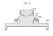
- [FIG. 9] FIG. 9 is a cross sectional view of the fourth variation of the endoscope attachment according to the first embodiment.
- [FIG. 10] FIG. 10A is a cross sectional view of the fifth variation of the endoscope attachment according to the first embodiment. FIG. 10B is a cross sectional view of the sixth variation of the endoscope attachment according to the first embodiment. FIG. 10C is a cross sectional view of the seventh variation of the endoscope attachment according to the first embodiment.
- [FIG. 11] FIG. 11A is an external view of a distal end of a probe of an endoscope to which the endoscope attachment according to the second embodiment is attached. FIG. 11B is a cross sectional view (taken along line A--A' of FIG. 11A) of the distal end of the probe of the endoscope to which the endoscope attachment according to the second embodiment is attached. FIG. 11C is a cross sectional view (taken along line B--B' of FIG. 3A) of the distal end of the probe of the endoscope to which the endoscope attachment according to the second embodiment is attached.
- [FIG. 12] FIG. 12A is an external view of a distal end of a probe of an endoscope to which the endoscope attachment according to the third embodiment is attached. FIG. 12B is a cross sectional view (taken along line A--A' of FIG. 12A) of the distal end of the probe of the endoscope to which the endoscope attachment according to the third embodiment is attached. FIG. 12C is a cross sectional view (taken along line B--B' of FIG. 3A) of the distal end of the probe of the endoscope to which the endoscope attachment according to the third embodiment is attached.
- [FIG. 13] FIG. 13A is an external view of a probe of the endoscope according to the present invention. FIG. 13B is a top view of a distal end of a probe of the endoscope according to the present invention.
- [FIG. 14] FIG. 14A is an external view of a probe of the conventional endoscope. FIG. 14B is a top view of a distal end of a probe of the endoscope of the conventional endoscope.
-
- 42
- hyperboloidal mirror
- 100
- attaching part
- 110, 1200, 1300
- image capturing part
- 120, 130, 1100
- holes
- 140
- convex part
- 150
- wide angle lens
- 151
- first mirror
- 171
- second mirror
- 200, 1000
- camera
- 210, 1040
- water injection nozzle
- 220, 1030
- forceps opening
- 230, 240, 1010, 1020
- lightings
- 820, 830, 860, 870
- rod lens
- 840, 850
- ball lens
- 900, 1330
- transparent members
- 1110
- hollow
- 1120, 1130, 1140
- light shielding films
- 1210, 1310
- mirrors
- 1211, 1311
- openings
- 1220, 1320
- support bars 1220
- The following describes an endoscope attachment according to the embodiments of the present invention with reference to the drawings.
- FIG. 1A is an external view of an endoscope attachment according to the first embodiment. FIGS. 1B and 1C are cross sectional views (taken along lines A--A' and B--B' of FIG. 1A) of the endoscope attachment.
- The endoscope attachment according to the first embodiment, which is made of transparent material such as glass or acrylic, is attachable to a probe of an endoscope. The endoscope attachment has: a flat-plate-shaped attaching
part 100 which is arranged to cover the distal end of the probe in order to attach the endoscope attachment to the probe; a cylindricalimage capturing part 110 which is used to enable a camera in the probe to capture images, and formed on a surface of the attachingpart 100 which is the opposite side of the surface contact with the distal end of the probe, in other words, on a top surface of the attachingpart 100. - In the attaching
part 100, twoholes part 100. Thehole 120 is a hole for a water injection nozzle in the probe. That is, thehole 120 prevents that any shielding exists in front of the water injection nozzle after the endoscope attachment being attached. Thehole 130 is a hole for forceps opening in the probe. That is, thehole 130 prevents that any shielding exists in front of the forceps opening after the endoscope attachment being attached. Here, relative positions of theholes part 100 and theimage capturing part 110 correspond to relative positions of the water injection nozzle, the forceps opening, and the camera at the distal end of the probe. - On the bottom surface of the attaching
part 100, aconvex part 140 is formed along the outer periphery of theattachment part 100. The endoscope attachment is combined to the endoscope, by being engaged with theconvex part 140 to the distal end of the probe of the endoscope. - In the cylinder of the
image capturing part 110, awide angle lens 150 having hyperboloid is arranged with the hyperboloid facing down. Thewide angle lens 150 is a lens for collecting light incident from a front view field with a wide angle. Thereby, as shown in a cross sectional view of the endoscope attachment of FIG. 2, on an image plane of the camera, a wide-angle view field is imaged in a central narrow view angle, so that it is possible to obtain a wide range view field with minimum resolution required for operating of the prove and the like. - Here, on the hyperboloid of the
wide angle lens 150, thefirst mirror 151 is formed to reflect light incident from a wide-angle side view field to be irradiated on the camera. Thereby, a hyperboloidal mirror, which forms one sheet of the two-sheeted hyperboloid, is formed, so that, as shown in FIG. 2, a wide-angle side view field is imaged on the image plane of the camera. Here, in order to enable the camera to capture image of an area in front of the endoscope, thefirst mirror 151 is not formed at center of the hyperboloid of thewide angle lens 150. The abovefirst mirror 151 is formed by masking the center of the hyperboloid and depositing metal such as aluminium, for example. It is assumed that the center of the camera lens in the probe is located at a focal point of the other sheet of the two-sheeted hyperboloid. An example of the camera using the hyperboloidal mirror is HyperOmni Vision proposed by Yamazawa et al., which will be described in detail further below. Note that the side view field obtained by the hyperboloidal mirror is adjacent to the front view field on the image plane but these view fields are not contiguous. - The
image capturing part 110 has a part of a flaring shape (hereinafter referred to as a trumpet shape) so that the illumination light illuminating the area in front of the probe is shielded. On an outer wall of the cylinder of theimage capturing part 110, the trumpet-shapedsecond mirror 171 is formed. Thesecond mirror 171 diffuses the illumination light incident from the probe and prevents the illumination light of the probe from being irradiated on thefirst mirror 151. Here, if all of the illumination light is irradiated on thesecond mirror 171, the illumination light is not provided to an area in front of the endoscope attachment, which makes it difficult to operate the probe. Therefore, a position and a size of thesecond mirror 171 are adjusted, so that a part of the illumination light can be provided to the area in front of the endoscope attachment and the illumination light can be prevented from being irradiated on thefirst mirror 151. - FIG. 3A is an external view of the distal end of the probe to which the above-structured endoscope attachment is attached. FIGS. 3B and 3C are cross sectional views (taken along lines A--A' and B--B' of FIG. 3A) of the distal end of the probe.
- A
camera 200 in the probe is to be positioned immediately under theimage capturing part 110 of the endoscope attachment, in order to capture images of areas in front and at sides of the endoscope, through the endoscope attachment. Here, the position of thecamera 200 is adjusted to be fit to theimage capturing part 110, using theholes water injection nozzle 210, and theforceps opening 220. More specifically, for the positioning, the convex part arranged at an opening of thehole 120 is engaged with an opening of thewater injection nozzle 210, and a convex part arranged at an opening of the forceps opening 220 is engaged with an opening of thehole 130. This is possible when the relative positions of theholes part 100 and theimage capturing part 110 correspond to the relative positions of thecamera 200, thewater injection nozzle 210, and the forceps opening 220 at the distal end of the probe. - Two
lightings part 100, in order to provide the illumination light from the outside of the cylinder of theimage capturing part 110 to the front side of the probe. A part of this illumination light is diffused by thesecond mirror 171 in the endoscope attachment and thereby illuminates areas at the sides of the endoscope attachment, while other parts of the illumination light illuminates an area in front of the endoscope attachment. - Next, the imaging processing, in which an input is an image signal obtained in the camera using the hyperboloidal mirror, is described.
- Referring to FIG. 4, the
hyperboloidal mirror 42 uses as a mirror the sheet of the two-sheeted hyperboloid that is located in the region where Z > 0. The two-sheeted hyperboloid is a curved surface obtained by rotating a hyperbolic curve about the real axis (Z-axis). The two-sheeted hyperboloid has two focal points (0,0,+c) and (0,0,-c). Where -

-


hyperboloidal mirror 42, which is provided in the region where Z > 0 so as to face downward in the vertical direction, and an imaging unit (not shown), which is provided therebelow so as to face upward in the vertical direction. In this case, thehyperboloidal mirror 42 and the imaging unit are positioned such that the focal point OM of thehyperboloidal mirror 42 and the lens center OC of the camera are located at two focal points (0,0,+c) and (0,0,-c), respectively, of the two-sheeted hyperboloid. The image plane xy is assumed to be a plane parallel to the XY plane and distanced by a focal distance f of the camera from the lens center OC of the imaging unit. The reflection surface of thehyperboloidal mirror 42, the focal point OM of thehyperboloidal mirror 42 and the lens center OC of the camera are expressed by the following equation (2). -

-

- Referring to FIG. 7, supposing a vertical section including the point P and the Z-axis, the relationship of the following equation (4) is established between the point P and the mapping point p.
-

hyperboloidal mirror 42 is uniquely obtained based on the mapping point p(x,y) by providing the lens center OC of the camera at the focal position of the hyperboloid. In this case, the focal point OM of thehyperboloidal mirror 42 is fixed, and therefore an input image can be transformed to an image (a panoramic image) viewed from the focal point OM of thehyperboloidal mirror 42, which is obtained by rotating the camera about the vertical axis, or a normal camera image. - The omnidirectional camera HyperOmni Vision is disclosed in detail in "Kazumasa Yamazawa et al., 'Omnidirectional Visual Sensors for Navigation of Mobile Robots', Journal of the Institute of Electronics, Information and Communication Engineers, D-II, Vol. J79-D-II, No. 5, pp. 698-707 (May, 1996)", etc.
- As described above, according to the endoscope attachment of the first embodiment, the
first mirror 151 forms the hyperboloidal mirror. Thereby, a view angle of the side view field is enlarged to obtain images of an omnidirectional view field, thereby capturing images of not only the areas merely positioned at the sides of the endoscope, but also front and rear sides of folds. Therefore, the endoscope attachment of the first embodiment can be realized as an endoscope attachment which enables an endoscope to eliminate any blind areas and prevent a physician from overlooking nidus. - Further, according to the endoscope attachment of the first embodiment, the endoscope attachment has: the
second mirror 171 which provides a part of the illumination light of the probe to the areas at sides of the endoscope attachment; thewide angle lens 150 which enables thecamera 200 to capture images of an area in front of the endoscope; and thefirst mirror 151 which enables thecamera 200 to capture images of areas at the sides of the endoscope. Thereby, the endoscope has the front view field and the side view field, and the illumination light can be provided in front and at the sides of the endoscope, so that the endoscope attachment of the first embodiment can be realized as an endoscope attachment which enables the endoscope to have not only the imaging system but also a lighting suitable for the imaging system thereby capturing images of the areas in front of and at the sides of the endoscope. - Furthermore, according to the endoscope attachment of the first embodiment, the endoscope attachment is attached to the distal end of the probe of the endoscope and then used. Thereby, the structure of the existing endoscope which has already been used in many medical institutions does not need to be changed but can still be used, so that the endoscope attachment of the first embodiment can be realized as an endoscope attachment which enables the endoscope to expand its functions easily and with a low cost.
- Still further, according to the endoscope attachment of the first embodiment, the endoscope attachment has: the attaching
part 100; and theimage capturing part 110 in which thewide angle lens 150 is arranged. Thereby, the endoscope attachment has a simple structure, so that the endoscope attachment of the first embodiment can be realized as an endoscope attachment which is easily cleansed thereby preventing spread of the disease to somebody else. - Still further, according to the endoscope attachment of the first embodiment, the
second mirror 171 prevents the illumination light of the probe from being irradiated on thefirst mirror 151. Thereby, the illumination light emitted from the probe is prevented from being irradiated on the camera as incident light, so that the endoscope attachment of the first embodiment can be realized as an endoscope attachment which prevents a part of image captured by the endoscope from being too brightened. - Still further, according to the endoscope attachment of the first embodiment, the endoscope attachment has the
holes camera 200 is adjusted to be fit to theimage capturing part 110, by engaging thewater injection nozzle 210 and the forceps opening 220 of the endoscope with theholes - Note that, as shown in FIG. 8A, on the outer wall of the cylinder of the
image capturing part 110, there may be two or more, for example two, trumpet-shaped parts. - Note that, as shown in FIG. 8B,
rod lenses part 100, which corresponds to the positions of the lightings at the distal end of the endoscope. Therod lenses rod lenses rod lenses rod lenses glass ball lenses rod lenses rod lenses ball lenses ball lenses ball lenses ball lenses image capturing part 110, so that the illumination light is prevented from being irradiated on the camera. - Note also that, as shown in FIG. 9, a
transparent member 900 may be formed at the top surface of the attachingpart 100. The position oftransparent member 900 corresponds to the position of the lighting at the distal end of the endoscope. Thetransparent member 900 has a hyperboloidal mirror for diffusing the illumination light from the probe to the areas at sides of the endoscope. Here, the hyperboloidal mirror has an opening from which the illumination light is provided to the area in front of the endoscope. - Note also that the
wide angle lens 150 may have a spherical surface, not the hyperboloid, and a reflection film may be formed on the spherical surface. - Note also that, as shown in FIG. 10A, the attaching
part 100 may have ahole 1100, so that any shielding does not exist in the front of thelighting 230 after the endoscope attachment being attached to the endoscope. - Note also that, as shown in FIG. 10B, the
image capturing part 110 may have a hollow 1110 which is positioned in front of thecamera 200 after the endoscope attachment being attached to the endoscope. - Note also that light shielding films may be formed on surfaces except: the surface through which the lighting of the probe is taken in and out; the surface on which the incident light from the side view field is irradiated; the surface on which the incident light from the front view field is irradiated; the surface where the second mirror is formed. More specifically, as shown in FIG. 10C, the
light shielding film 1120 may be formed on the top surface of the attachingpart 100 except the surfaces through which thelighting 230 of the probe is taken in and out. Further, thelight shielding film 1130 may be formed on the side surface of theimage capturing part 110 except the surface on which incident light from the side view field is irradiated and the surface on which thesecond mirror 171 is formed. Furthermore, thelight shielding film 1140 may be formed on the top surface of theimage capturing part 110 except the surface on which the incident light from the front view field is irradiated. - FIG. 11A is an external view of a distal end of a probe of an endoscope to which an endoscope attachment according to the second embodiment is attached. FIG. 11B and 11C are cross sectional views (taken along lines A--A' and B--B' of FIG. 11A) of the distal end of the probe of the endoscope to which the endoscope attachment is attached.
- The endoscope attachment according to the second embodimet has: the flat-plate-shaped attaching
part 100; and animage capturing part 1200 which is used to enable the camera of the probe to capture images, and formed on a surface of the attachingpart 100 which is the opposite side of the surface contact with the distal end of the probe, in other words, on a top surface of the attachingpart 100. - The
image capturing part 1200 has: three (for example)support bars 1220 arranged along the outer periphery of the attachingpart 100; and aconvex mirror 1210 which has a ring shape and is fixed to the attachingpart 100 by the support bars 1220. Note that the ring-shapedconvex mirror 1210 fixed to the attachingpart 100 may be a plane-shaped mirror. - Here, the
mirror 1210 has a hyperboloid for reflecting the incident light from the wide-angle side view field to be irradiated on the camera. Thereby, a hyperboloidal mirror, which forms one sheet of the two-sheeted hyperboloid, is formed, so that, as shown in FIG. 11B, the wide-angle side view field is imaged on the image plane of the camera. Here, in order to enable the camera to capture image of an area in front of the endoscope, anopening 1211 is formed at center of the hyperboloid of themirror 1210. - Furthermore, the
mirror 1210 diffuses the illumination light from the probe to be provided to the areas at sides of the endoscope. Here, if all of the illumination light is irradiated on themirror 1210, the illumination light is not provided to the area in front of the endoscope attachment, which makes it difficult to operate the probe. Therefore, a position and a size of theopening 1211 is adjusted, so that a part of the illumination light can be provided to the area in front of the endoscope attachment. Furthermore, in order to prevent regular reflection light of the illumination light from being irradiated on themirror 1210, theopening 1211 is positioned at a part of themirror 1210 where the illumination light is reflected regularly towards the camera. Further, in order not to disturb cleansing of thewater injection nozzle 210 and taking in and out of the forceps, theopening 1211 is positioned at a part of themirror 1210 which is in front of thewater injection nozzle 210 and the forceps opening 220 and is in a range where thewater injection nozzle 210 and the forceps can move. Note that the greater an outside diameter of themirror 1210 is, the wider the side view field becomes, so that the outside diameter of themirror 1210 is determined depending on a width of the necessary side view field. Note also that a curvature of the outer periphery of themirror 1210 is determined depending on a maximum height of themirror 1210 and a minimum elevation angle of themirror 1210. Note also that a curvature of theopening 1211 of themirror 1210 is determined so that the probe is not projected on the image plane. Note also that a diameter of theopening 1211 of themirror 1210 is determined so that regular reflection light on the mirror surface is not irradiated on the image plane, and that a range where the forceps opening 220 can move is not restricted. - As described above, according to the endoscope attachment of the second embodiment, the
mirror 1210 forms a hyperboloidal mirror. Thereby, a view angle of the side view field is enlarged to obtain images of an omnidirectional view field, thereby capturing images of not only the areas merely positioned at the sides of the endoscope, but also front and rear sides of folds. Thus, it is possible to realize an endoscope attachment which enables an endoscope to eliminate any blind areas and prevent a physician from overlooking nidus. - Further, according to the endoscope attachment of the second embodiment, the endoscope attachment has: the
mirror 1210 which provides a part of the illumination light of the probe to the areas at sides of the endoscope attachment, and enables thecamera 200 to capture images of the areas. Here, themirror 1210 has theopening 1211 through which thecamera 200 can capture the images of the area in front of the endoscope attachment. Thereby, the endoscope has the front view field and the side view field, and the illumination light can be provided in front and at the sides of the endoscope, so that it is possible to realize an endoscope attachment which enables the endoscope to have not only the imaging system but also a lighting suitable for the imaging system thereby capturing images of the areas in front of and at the sides of the endoscope. - Furthermore, according to the endoscope attachment of the second embodiment, the endoscope attachment is attached to the distal end of the probe of the endoscope and then used. Thereby, it is possible to realize an endoscope attachment which enables the endoscope to expand its functions easily and with a low cost.
- Still further, according to the endoscope attachment of the second embodiment, the endoscope attachment has: the attaching
part 100; and theimage capturing part 1200. Thereby, the endoscope attachment has a simple structure, so that it is possible to realize an endoscope attachment which is easily cleansed thereby preventing spread of the disease to somebody else. - Still further, according to the endoscope attachment of the second embodiment, the
opening 1211 is formed within an area of themirror 1210 where the illumination light from themirror 1210 is reflected regularly to the camera. Thereby, the illumination light emitted from the probe is prevented from being irradiated on the camera as incident light, so that it is possible to realize an endoscope attachment which prevents a part of image captured by the endoscope from being too brightened. - Still further, according to the endoscope attachment of the second embodiment, the endoscope attachment has the
holes camera 200 is adjusted to be fit to theimage capturing part 110, by engaging thewater injection nozzle 210 and the forceps opening 220 of the endoscope with theholes - FIG. 12A is an external view of a distal end of a probe of an endoscope to which the endoscope attachment according to the third embodiment is attached. FIGS. 12B and 12C are cross sectional views (taken along lines A--A' and B--B' of FIG. 12A) of the distal end of the probe of the endoscope to which the endoscope attachment.
- The endoscope attachment according to the third embodiment has: the flat-plate-shaped attaching
part 100; animage capturing part 1300 which is used to enable the camera of the probe to capture images, and formed on a surface of the attachingpart 100 which is the opposite side of the surface contact with the distal end of the probe, in other words, on a top surface of the attachingpart 100; and atransparent member 1330 formed on the top surface of the attachingpart 100 at a position corresponding to the position of the lighting at the distal end of the endoscope. - The
image capturing part 1300 has: multiple (three, for example) support bars 1320; and aconvex mirror 1310 which has a ring shape and is fixed to the attachingpart 100 by the support bars 1320. Theimage capturing part 1300 is arranged to be positioned above thecamera 200 only. - Here, the
mirror 1310 has a hyperboloid for reflecting the incident light from the wide-angle side view field to be irradiated on the camera. Thereby, a hyperboloidal mirror, which forms one sheet of the two-sheeted hyperboloid, is formed, so that, as shown in FIG. 12B, the wide-angle side view field is imaged on the image plane of the camera. Here, in order to enable the camera to capture image of an area in front of the endoscope, anopening 1311 is formed at center of the hyperboloid of themirror 1310. - The
transparent member 1330 has a hyperboloidal mirror for diffusing the illumination light from the probe to the areas at the sides of the endoscope. Here, the hyperboloidal mirror has anopening 1311 for providing the illumination light to the area in front of the endoscope. - As described above, according to the endoscope attachment of the third embodiment, the
mirror 1310 forms a hyperboloidal mirror. Thereby, a view angle of the side view field is enlarged to obtain capture images of an omnidirectional view field, thereby capturing images of not only the areas merely positioned at the sides of the endoscope, but also front and rear sides of folds. Thus, it is possible to realize an endoscope attachment which enables the endoscope to eliminate any blind areas and prevent a physician from overlooking nidus. - Further, according to the endoscope attachment of the third embodiment, the endoscope attachment has: the
transparent member 1330 which provides a part of the illumination light of the probe to the areas at sides of the endoscope attachment; and themirror 1310 which enables thecamera 200 to capture images of the areas. Here, themirror 1310 has theopening 1311 through which thecamera 200 can capture the images of the area in front of the endoscope attachment. Thereby, the endoscope has the front view field and the side view field, and the illumination light can be provided in front and at the sides of the endoscope, so that it is possible to realize an endoscope attachment which enables the endoscope to have not only the imaging system but also a lighting suitable for the imaging system thereby capturing images of the areas in front of and at the sides of the endoscope. - Furthermore, according to the endoscope attachment of the third embodiment, the endoscope attachment is attached to the distal end of the probe of the endoscope and then used. Thereby, it is possible to realize an endoscope attachment which enables the endoscope to expand its functions easily and with a low cost.
- Still further, according to the endoscope attachment of the third embodiment, the endoscope attachment has: the attaching
part 100; theimage capturing part 1300; and thetransparent member 1330. Thereby, the endoscope attachment has a simple structure, so that it is possible to realize an endoscope attachment which is easily cleansed thereby preventing spread of the disease to somebody else. - Still further, according to the endoscope attachment of the third embodiment, the endoscope attachment has the
holes camera 200 is adjusted to be fit to theimage capturing part 110, by engaging thewater injection nozzle 210 and the forceps opening 220 of the endoscope with theholes - While the endoscope attachment according to the present invention has been described having reference to the above preferred embodiments, those having skill in the art will appreciate that the present invention is not limited to the above embodiments and other variations and modifications may be made without departing from the spirit and scope of the present invention.
- For example, the present invention may be an endoscope whose probe has a distal end having a structure of the endoscope attachment according to the present invention. More specifically, the present invention may be an endoscope whose probe has a distal end having: the
convex mirror 1310 which has a ring shape and is fixed to the distal end of the endoscope by the threesupport bars 1320, so that theconvex mirror 1310 is positioned above thecamera 200 only; and thetransparent members 1330 each of which is formed at a position corresponding to the position of each fighting, as shown in an external view of FIG. 13A and a top view of FIG. 13B. - The present invention is able to be used as an endoscope attachment, and especially as an endoscope attachment or the like which is attachable to an endoscope for imaging the inside of digestive organs.
Claims (23)
- An endoscope attachment which is attachable to a distal end of a probe of an endoscope used to image a digestive organ, said attachment comprising:a view field obtaining part operable to obtain a front view field and a side view field for the probe; anda convex-shaped illumination light providing part operable to diffuse illumination light illuminating an area in front of the probe in order to provide the illumination light to an area at side of the endoscope attachment.
- The endoscope attachment according to Claim 1,
wherein said view field obtaining part is an optical-lens transparent member which has a predetermined-shaped surface on a part of which a mirror is formed,
an image of the area at side of the probe is captured by the camera of the probe via the mirror, and
an image of the area in front of the probe is captured by the camera via a part of the predetermined-shaped surface of the optical-lens transparent member, on the part the mirror not being formed. - The endoscope attachment according to Claim 2,
wherein the optical-lens transparent member is a wide angle lens. - The endoscope attachment according to Claim 3,
wherein the predetermined-shaped surface is a convex surface. - The endoscope attachment according to Claim 4,
wherein the predetermined-shaped surface is a hyperboloid. - The endoscope attachment according to Claim 4,
wherein the predetermined-shaped surface is a spherical surface. - The endoscope attachment according to Claim 1,
wherein said view field obtaining part is a ring-shaped mirror having an opening,
an image of the area at side of the probe is captured by the camera of the probe via the mirror, and
an image of the area in front of the probe is captured by the camera through the opening of the mirror. - The endoscope attachment according to Claim 7,
wherein the mirror also has a convex shape. - The endoscope attachment according to Claim 7,
wherein said illumination light providing part is the ring-shaped mirror which is used also as said view field obtaining part. - The endoscope attachment according to Claim 7,
wherein the opening of the mirror is positioned at a range where forceps can move. - The endoscope attachment according to Claim 7,
wherein said endoscope attachment has a support member by which the mirror is fixed to said endoscope attachment. - The endoscope attachment according to Claim 7,
wherein the opening is positioned at an area of the mirror, on the area the illumination light being regularly reflected to the camera. - The endoscope attachment according to Claim 1,
wherein said illumination light providing part is a first mirror which has a trumpet shape flaring out in order to shield the illumination light illuminating an area in front of the probe. - The endoscope attachment according to Claim 13,
wherein said illumination light providing part has a plurality of the first mirrors. - The endoscope attachment according to Claim 13,
wherein the first mirror is operable to diffuse a part of the illumination light illuminating the area in front of the probe, in order to provide the part of the illumination light to an area at side of the endoscope attachment. - The endoscope attachment according to Claim 13,
wherein said view field obtaining part is an optical-lens transparent member having a predetermined-shaped surface on a part of which a second mirror is formed, the transparent member being arranged in a cylindrical housing of said endoscope attachment,
the first mirror is arranged on an outer wall of the housing, and
the second mirror is operable to prevent the illumination light illuminating the area in front of the probe from being irradiated on the first mirror. - The endoscope attachment according to Claim 1,
wherein said illumination light providing part is a conical or cylindrical transparent optical member which protrudes ahead of the probe. - The endoscope attachment according to Claim 17,
wherein on a side surface of the conical or cylindrical transparent optical member, a mirror surface is formed. - The endoscope attachment according to Claim 17,
wherein on a side surface of the conical or cylindrical transparent optical member, a diffuse reflection surface is formed. - The endoscope attachment according to Claim 1,
wherein said illumination light providing part is an optical-lens transparent member having a convex surface on a part of which a mirror is formed, and
the mirror is operable to diffuse a part of the illumination light illuminating an area in front of the probe in order to provide the part of the illumination light to an area at side of the endoscope attachment. - The endoscope attachment according to Claim 1 further comprising,
a transparent attaching part, which has two through-holes, operable to be used to attach said endoscope attachment to the probe,
wherein relative positions of the holes in said endoscope attachment correspond to relative positions of a forceps opening and a water injection nozzle of the probe, respectively. - The endoscope attachment according to Claim 1
wherein said view field obtaining part is operable to obtain an omnidirectional view field for the probe. - An endoscope which is used to image a digestive organ, said endoscope comprising:a view field obtaining part, which is arranged at a distal end of a probe of said endoscope, operable to obtain a front view field and a side view field for the probe; anda convex-shaped illumination light providing part, which is arranged at the distal end of the probe of said endoscope, operable to diffuse illumination light illuminating an area in front of the probe in order to provide the illumination light to an area at side of the endoscope attachment.
Applications Claiming Priority (2)
| Application Number | Priority Date | Filing Date | Title |
|---|---|---|---|
| JP2004197355 | 2004-07-02 | ||
| PCT/JP2005/012321 WO2006004083A1 (en) | 2004-07-02 | 2005-07-04 | Endoscope attachment and endoscope |
Publications (3)
| Publication Number | Publication Date |
|---|---|
| EP1769718A1 true EP1769718A1 (en) | 2007-04-04 |
| EP1769718A4 EP1769718A4 (en) | 2009-02-25 |
| EP1769718B1 EP1769718B1 (en) | 2011-09-07 |
Family
ID=35782884
Family Applications (1)
| Application Number | Title | Priority Date | Filing Date |
|---|---|---|---|
| EP05765238A Expired - Fee Related EP1769718B1 (en) | 2004-07-02 | 2005-07-04 | Endoscope attachment and endoscope |
Country Status (4)
| Country | Link |
|---|---|
| US (1) | US7922655B2 (en) |
| EP (1) | EP1769718B1 (en) |
| JP (1) | JP4779120B2 (en) |
| WO (1) | WO2006004083A1 (en) |
Cited By (9)
| Publication number | Priority date | Publication date | Assignee | Title |
|---|---|---|---|---|
| EP2163933A1 (en) * | 2007-06-12 | 2010-03-17 | Olympus Corporation | Optical element, optical system, and endoscope using same |
| JP2011517613A (en) * | 2008-04-14 | 2011-06-16 | カーネギー メロン ユニバーシティ | Articulated device with visualization system |
| EP2306232A3 (en) * | 2009-09-30 | 2011-12-21 | Olympus Corporation | Optical system |
| EP2420178A1 (en) * | 2009-11-06 | 2012-02-22 | Olympus Medical Systems Corp. | Endoscope device and endoscope |
| US8212862B2 (en) | 2009-11-06 | 2012-07-03 | Olympus Medical Systems Corp. | Endoscope system |
| US8343043B2 (en) | 2009-11-06 | 2013-01-01 | Olympus Medical Systems Corp. | Endoscope |
| EP2570072A1 (en) * | 2011-03-31 | 2013-03-20 | Olympus Medical Systems Corp. | Method for assembling endoscopic imaging unit and endoscope |
| EP2929830A4 (en) * | 2012-12-05 | 2016-10-26 | Olympus Corp | Endoscope device |
| WO2022043835A1 (en) * | 2020-08-31 | 2022-03-03 | Hoya Corporation | Illumination device for an endoscope |
Families Citing this family (91)
| Publication number | Priority date | Publication date | Assignee | Title |
|---|---|---|---|---|
| EP1765142A4 (en) * | 2004-05-14 | 2007-10-10 | G I View Ltd | Omnidirectional and forward-looking imaging device |
| US8182422B2 (en) | 2005-12-13 | 2012-05-22 | Avantis Medical Systems, Inc. | Endoscope having detachable imaging device and method of using |
| WO2006120690A2 (en) * | 2005-05-13 | 2006-11-16 | G.I. View Ltd. | Endoscopic measurement techniques |
| US20100220836A1 (en) | 2005-09-08 | 2010-09-02 | Feke Gilbert D | Apparatus and method for multi-modal imaging |
| US8203132B2 (en) * | 2005-09-08 | 2012-06-19 | Carestream Health, Inc. | Apparatus and method for imaging ionizing radiation |
| US20090281383A1 (en) * | 2005-09-08 | 2009-11-12 | Rao Papineni | Apparatus and method for external fluorescence imaging of internal regions of interest in a small animal using an endoscope for internal illumination |
| US8660631B2 (en) * | 2005-09-08 | 2014-02-25 | Bruker Biospin Corporation | Torsional support apparatus and method for craniocaudal rotation of animals |
| WO2007087421A2 (en) | 2006-01-23 | 2007-08-02 | Avantis Medical Systems, Inc. | Endoscope |
| JP4967096B2 (en) * | 2006-05-18 | 2012-07-04 | 国立大学法人島根大学 | Endoscope, endoscope attachment, and endoscope apparatus |
| DE102007015492B4 (en) * | 2007-01-30 | 2011-03-24 | Fraunhofer-Gesellschaft zur Förderung der angewandten Forschung e.V. | Illumination device for an image capture device at the distal end of an endoscope |
| US20100010302A1 (en) * | 2007-02-26 | 2010-01-14 | Vision-Sciences Inc. | Endoscopic reflector |
| US8064666B2 (en) | 2007-04-10 | 2011-11-22 | Avantis Medical Systems, Inc. | Method and device for examining or imaging an interior surface of a cavity |
| WO2009053989A2 (en) * | 2007-10-24 | 2009-04-30 | Technion Research & Development Foundation Ltd. | Multi-view endoscopic imaging system |
| JP2010099178A (en) * | 2008-10-22 | 2010-05-06 | Osaka Univ | Apparatus and method for image processing |
| US20100284665A1 (en) * | 2009-05-05 | 2010-11-11 | Doody Michael C | Light Diffusing Safety Cap |
| US7991260B2 (en) * | 2009-05-05 | 2011-08-02 | Sensormed, Inc. | Light-diffusing safety cap |
| US9474440B2 (en) | 2009-06-18 | 2016-10-25 | Endochoice, Inc. | Endoscope tip position visual indicator and heat management system |
| US9101287B2 (en) | 2011-03-07 | 2015-08-11 | Endochoice Innovation Center Ltd. | Multi camera endoscope assembly having multiple working channels |
| US9706903B2 (en) | 2009-06-18 | 2017-07-18 | Endochoice, Inc. | Multiple viewing elements endoscope system with modular imaging units |
| WO2012120507A1 (en) | 2011-02-07 | 2012-09-13 | Peermedical Ltd. | Multi-element cover for a multi-camera endoscope |
| US10165929B2 (en) | 2009-06-18 | 2019-01-01 | Endochoice, Inc. | Compact multi-viewing element endoscope system |
| US11864734B2 (en) | 2009-06-18 | 2024-01-09 | Endochoice, Inc. | Multi-camera endoscope |
| US9901244B2 (en) | 2009-06-18 | 2018-02-27 | Endochoice, Inc. | Circuit board assembly of a multiple viewing elements endoscope |
| US9554692B2 (en) | 2009-06-18 | 2017-01-31 | EndoChoice Innovation Ctr. Ltd. | Multi-camera endoscope |
| US9642513B2 (en) | 2009-06-18 | 2017-05-09 | Endochoice Inc. | Compact multi-viewing element endoscope system |
| US9872609B2 (en) | 2009-06-18 | 2018-01-23 | Endochoice Innovation Center Ltd. | Multi-camera endoscope |
| US9492063B2 (en) | 2009-06-18 | 2016-11-15 | Endochoice Innovation Center Ltd. | Multi-viewing element endoscope |
| US11278190B2 (en) | 2009-06-18 | 2022-03-22 | Endochoice, Inc. | Multi-viewing element endoscope |
| US10130246B2 (en) | 2009-06-18 | 2018-11-20 | Endochoice, Inc. | Systems and methods for regulating temperature and illumination intensity at the distal tip of an endoscope |
| US9713417B2 (en) | 2009-06-18 | 2017-07-25 | Endochoice, Inc. | Image capture assembly for use in a multi-viewing elements endoscope |
| WO2012038958A2 (en) | 2010-09-20 | 2012-03-29 | Peermedical Ltd. | Multi-camera endoscope having fluid channels |
| US10524645B2 (en) | 2009-06-18 | 2020-01-07 | Endochoice, Inc. | Method and system for eliminating image motion blur in a multiple viewing elements endoscope |
| US9402533B2 (en) * | 2011-03-07 | 2016-08-02 | Endochoice Innovation Center Ltd. | Endoscope circuit board assembly |
| US8926502B2 (en) | 2011-03-07 | 2015-01-06 | Endochoice, Inc. | Multi camera endoscope having a side service channel |
| US9101268B2 (en) | 2009-06-18 | 2015-08-11 | Endochoice Innovation Center Ltd. | Multi-camera endoscope |
| US11547275B2 (en) | 2009-06-18 | 2023-01-10 | Endochoice, Inc. | Compact multi-viewing element endoscope system |
| JP5560506B2 (en) * | 2009-08-31 | 2014-07-30 | 国立大学法人鳥取大学 | Endoscope |
| DE102009043523A1 (en) * | 2009-09-30 | 2011-04-07 | Siemens Aktiengesellschaft | endoscope |
| WO2011055395A1 (en) * | 2009-11-06 | 2011-05-12 | Universita' Degli Studi Di Firenze | Ingestible capsule for treating gastric infections, in particular for treating h. pylori infections |
| EP2497406B9 (en) * | 2009-11-06 | 2018-08-08 | Olympus Corporation | Endoscope system |
| JP2011152202A (en) * | 2010-01-26 | 2011-08-11 | Olympus Corp | Image acquiring device, observation device, and observation system |
| JP4955838B2 (en) * | 2010-07-08 | 2012-06-20 | オリンパスメディカルシステムズ株式会社 | Endoscope |
| US9560953B2 (en) | 2010-09-20 | 2017-02-07 | Endochoice, Inc. | Operational interface in a multi-viewing element endoscope |
| CN103403605A (en) | 2010-10-28 | 2013-11-20 | 恩多巧爱思创新中心有限公司 | Optical systems for multi-sensor endoscopes |
| US9706908B2 (en) | 2010-10-28 | 2017-07-18 | Endochoice, Inc. | Image capture and video processing systems and methods for multiple viewing element endoscopes |
| US10663714B2 (en) | 2010-10-28 | 2020-05-26 | Endochoice, Inc. | Optical system for an endoscope |
| US11889986B2 (en) | 2010-12-09 | 2024-02-06 | Endochoice, Inc. | Flexible electronic circuit board for a multi-camera endoscope |
| US9814374B2 (en) | 2010-12-09 | 2017-11-14 | Endochoice Innovation Center Ltd. | Flexible electronic circuit board for a multi-camera endoscope |
| EP2648602B1 (en) | 2010-12-09 | 2018-07-18 | EndoChoice Innovation Center Ltd. | Flexible electronic circuit board multi-camera endoscope |
| JP5608580B2 (en) * | 2011-02-01 | 2014-10-15 | オリンパスメディカルシステムズ株式会社 | Endoscope |
| US10517464B2 (en) | 2011-02-07 | 2019-12-31 | Endochoice, Inc. | Multi-element cover for a multi-camera endoscope |
| EP2604175B1 (en) | 2011-12-13 | 2019-11-20 | EndoChoice Innovation Center Ltd. | Removable tip endoscope |
| EP2604172B1 (en) | 2011-12-13 | 2015-08-12 | EndoChoice Innovation Center Ltd. | Rotatable connector for an endoscope |
| EP2861124B1 (en) * | 2012-06-13 | 2019-06-26 | Boston Scientific Scimed, Inc. | Medical device visualization system |
| KR20140005418A (en) * | 2012-07-03 | 2014-01-15 | 삼성전자주식회사 | Endoscope and endoscope system |
| US9560954B2 (en) | 2012-07-24 | 2017-02-07 | Endochoice, Inc. | Connector for use with endoscope |
| JP5715308B2 (en) * | 2013-02-20 | 2015-05-07 | オリンパスメディカルシステムズ株式会社 | Endoscope device |
| US9986899B2 (en) | 2013-03-28 | 2018-06-05 | Endochoice, Inc. | Manifold for a multiple viewing elements endoscope |
| US9993142B2 (en) | 2013-03-28 | 2018-06-12 | Endochoice, Inc. | Fluid distribution device for a multiple viewing elements endoscope |
| US9636003B2 (en) | 2013-06-28 | 2017-05-02 | Endochoice, Inc. | Multi-jet distributor for an endoscope |
| US10595714B2 (en) | 2013-03-28 | 2020-03-24 | Endochoice, Inc. | Multi-jet controller for an endoscope |
| EP2994034B1 (en) | 2013-05-07 | 2020-09-16 | EndoChoice, Inc. | White balance enclosure for use with a multi-viewing elements endoscope |
| US10499794B2 (en) | 2013-05-09 | 2019-12-10 | Endochoice, Inc. | Operational interface in a multi-viewing element endoscope |
| US9949623B2 (en) | 2013-05-17 | 2018-04-24 | Endochoice, Inc. | Endoscope control unit with braking system |
| WO2014197241A1 (en) * | 2013-06-05 | 2014-12-11 | The Arizona Board Of Regents On Behalf Of The University Of Arizona | Dual-view probe for illumination and imaging, and use thereof |
| JP6470273B2 (en) | 2013-06-19 | 2019-02-13 | ザ ジェネラル ホスピタル コーポレイション | Omnidirectional visual device |
| US10064541B2 (en) | 2013-08-12 | 2018-09-04 | Endochoice, Inc. | Endoscope connector cover detection and warning system |
| US9943218B2 (en) | 2013-10-01 | 2018-04-17 | Endochoice, Inc. | Endoscope having a supply cable attached thereto |
| US9968242B2 (en) | 2013-12-18 | 2018-05-15 | Endochoice, Inc. | Suction control unit for an endoscope having two working channels |
| EP3096176A4 (en) * | 2014-01-15 | 2018-01-03 | Olympus Corporation | Endoscope device |
| WO2015112747A2 (en) | 2014-01-22 | 2015-07-30 | Endochoice, Inc. | Image capture and video processing systems and methods for multiple viewing element endoscopes |
| US10334163B2 (en) | 2014-02-26 | 2019-06-25 | Ecole Polytechnique Federale De Lausanne (Epfl) | Large field of view multi-camera endoscopic apparatus with omni-directional illumination |
| US11234581B2 (en) | 2014-05-02 | 2022-02-01 | Endochoice, Inc. | Elevator for directing medical tool |
| US10258222B2 (en) | 2014-07-21 | 2019-04-16 | Endochoice, Inc. | Multi-focal, multi-camera endoscope systems |
| JP6665164B2 (en) | 2014-08-29 | 2020-03-13 | エンドチョイス インコーポレイテッドEndochoice, Inc. | Endoscope assembly |
| EP3235241B1 (en) | 2014-12-18 | 2023-09-06 | EndoChoice, Inc. | System for processing video images generated by a multiple viewing elements endoscope |
| US10271713B2 (en) | 2015-01-05 | 2019-04-30 | Endochoice, Inc. | Tubed manifold of a multiple viewing elements endoscope |
| US10376181B2 (en) | 2015-02-17 | 2019-08-13 | Endochoice, Inc. | System for detecting the location of an endoscopic device during a medical procedure |
| US10078207B2 (en) | 2015-03-18 | 2018-09-18 | Endochoice, Inc. | Systems and methods for image magnification using relative movement between an image sensor and a lens assembly |
| US10401611B2 (en) | 2015-04-27 | 2019-09-03 | Endochoice, Inc. | Endoscope with integrated measurement of distance to objects of interest |
| ES2818174T3 (en) | 2015-05-17 | 2021-04-09 | Endochoice Inc | Endoscopic image enhancement using contrast-limited adaptive histogram equalization (CLAHE) implemented in a processor |
| EP3367950A4 (en) | 2015-10-28 | 2019-10-02 | Endochoice, Inc. | Device and method for tracking the position of an endoscope within a patient's body |
| CN113425225A (en) | 2015-11-24 | 2021-09-24 | 安多卓思公司 | Disposable air/water and suction valve for endoscope |
| GB2547104B (en) * | 2015-12-15 | 2020-01-29 | Ev Offshore Ltd | Inspection assembly |
| EP3419497B1 (en) | 2016-02-24 | 2022-06-01 | Endochoice, Inc. | Circuit board assembly for a multiple viewing element endoscope using cmos sensors |
| US10292570B2 (en) * | 2016-03-14 | 2019-05-21 | Endochoice, Inc. | System and method for guiding and tracking a region of interest using an endoscope |
| US10993605B2 (en) | 2016-06-21 | 2021-05-04 | Endochoice, Inc. | Endoscope system with multiple connection interfaces to interface with different video data signal sources |
| JP2019032393A (en) * | 2017-08-07 | 2019-02-28 | オリンパス株式会社 | Endoscope tip part, endoscope, and optical adaptor |
| US11219355B2 (en) | 2017-08-14 | 2022-01-11 | Medos International Sarl | Surgical instruments with reflective mirror-like surfaces |
| WO2020065756A1 (en) | 2018-09-26 | 2020-04-02 | オリンパス株式会社 | Endoscope device, endoscope image processing device, and operating method for endoscope image processing device |
| CN114018948A (en) * | 2021-11-11 | 2022-02-08 | 合肥君信电子科技有限公司 | Detection probe for endoscope |
Citations (5)
| Publication number | Priority date | Publication date | Assignee | Title |
|---|---|---|---|---|
| JPH11125773A (en) * | 1997-10-21 | 1999-05-11 | Olympus Optical Co Ltd | Endoscope |
| US6142932A (en) * | 1998-06-19 | 2000-11-07 | Fuji Photo Optical Co., Ltd. | Front end structure of stereoscopic endoscope including an elongated lens |
| JP2001299679A (en) * | 2000-04-25 | 2001-10-30 | Keyence Corp | Adaptor for changing light passage and endoscope |
| US6387044B1 (en) * | 1998-12-02 | 2002-05-14 | J. Morita Manufacturing Corporation | Laparoscope apparatus |
| WO2004008185A2 (en) * | 2002-07-15 | 2004-01-22 | O.D.F. Optronics, Ltd. | Optical lens providing omni-directional coverage and illumination |
Family Cites Families (32)
| Publication number | Priority date | Publication date | Assignee | Title |
|---|---|---|---|---|
| US2987960A (en) * | 1958-02-17 | 1961-06-13 | Bausch & Lomb | Optical system for endoscopes and the like |
| US3413067A (en) * | 1964-03-25 | 1968-11-26 | Froio Corp | Light conducting rod endoscopic instrument which makes use of the principle of total internal reflection to sight perpendicularly to the rod axis |
| US3548808A (en) * | 1967-11-22 | 1970-12-22 | Olympus Optical Co | Device for switching the direction of the observation in an endoscope |
| JPS49130235A (en) * | 1973-04-16 | 1974-12-13 | ||
| JPS57125731A (en) * | 1981-01-26 | 1982-08-05 | Olympus Optical Co | Illumination system for endoscope |
| BR8303781A (en) | 1982-07-28 | 1984-04-24 | Goodyear Tire & Rubber | Unsaturated polyurethane and process for its production |
| JPS5941322U (en) * | 1982-09-09 | 1984-03-16 | オリンパス光学工業株式会社 | Endoscope illumination device |
| JPS6286323A (en) * | 1985-10-11 | 1987-04-20 | Olympus Optical Co Ltd | Side viewing type endoscope |
| US4699463A (en) * | 1985-11-01 | 1987-10-13 | Circon Corporation | Multidirectional viewing borescope |
| US4846154A (en) * | 1988-06-13 | 1989-07-11 | Macanally Richard B | Dual view endoscope |
| US4838247A (en) * | 1988-10-06 | 1989-06-13 | Baxter International, Inc. | Dual-view arthroscope |
| JPH04279141A (en) * | 1991-03-05 | 1992-10-05 | Olympus Optical Co Ltd | Endoscope |
| US6450950B2 (en) * | 1992-11-12 | 2002-09-17 | Karl Storz Gmbh & Co. Kg | Endoscope having stereo-lateral-view optics |
| JPH06160734A (en) | 1992-11-16 | 1994-06-07 | Mitsubishi Cable Ind Ltd | Side view type endoscope |
| US5447148A (en) * | 1993-07-08 | 1995-09-05 | Vision Sciences, Inc. | Endoscopic contamination protection system to facilitate cleaning of endoscopes |
| JPH07113962A (en) * | 1993-10-15 | 1995-05-02 | Olympus Optical Co Ltd | Endoscope with protective cover |
| US5940126A (en) * | 1994-10-25 | 1999-08-17 | Kabushiki Kaisha Toshiba | Multiple image video camera apparatus |
| AU5620296A (en) * | 1995-06-27 | 1997-01-09 | Yoshihisa Furuta | Device for checking lateral views at front/rear ends of vehicle |
| JP3001035B2 (en) | 1995-10-03 | 2000-01-17 | オリンパス光学工業株式会社 | Optical adapter for endoscope |
| US6095970A (en) | 1997-02-19 | 2000-08-01 | Asahi Kogaku Kogyo Kabushiki Kaisha | Endoscope |
| JP3665443B2 (en) * | 1997-02-19 | 2005-06-29 | ペンタックス株式会社 | Endoscope |
| JP4011673B2 (en) * | 1997-05-13 | 2007-11-21 | オリンパス株式会社 | Endoscope optical system |
| JP3523783B2 (en) * | 1998-05-14 | 2004-04-26 | 康史 八木 | Omnidirectional viewing angle sensor |
| JP4063955B2 (en) | 1998-05-15 | 2008-03-19 | フジノン株式会社 | Endoscope structure of endoscope |
| US6736773B2 (en) * | 2001-01-25 | 2004-05-18 | Scimed Life Systems, Inc. | Endoscopic vision system |
| JP3791899B2 (en) | 2001-02-09 | 2006-06-28 | シャープ株式会社 | Imaging apparatus and endoscope system including the same |
| JP2002341409A (en) * | 2001-05-21 | 2002-11-27 | Accowle Co Ltd | Omniazimuth photographing device |
| US20030050273A1 (en) | 2001-08-29 | 2003-03-13 | Keiya Ozawa | Compositions and methods for treating neurodegenerative diseases |
| EP1452899A1 (en) * | 2001-11-13 | 2004-09-01 | Matsushita Electric Industrial Co., Ltd. | Wide-angle imaging optical system and wide-angle imaging device, monitoring imaging device, on-vehicle imaging device and projection device with the wide-angle imaging optical system |
| JP2003164418A (en) | 2001-11-30 | 2003-06-10 | Olympus Optical Co Ltd | Endoscope device |
| US8585584B2 (en) * | 2004-10-11 | 2013-11-19 | Nitesh Ratnakar | Dual view endoscope |
| US20090112061A1 (en) * | 2007-10-25 | 2009-04-30 | Dhs Company Ltd. | Endoscope capable of varying field of vision |
-
2005
- 2005-07-04 US US11/630,956 patent/US7922655B2/en not_active Expired - Fee Related
- 2005-07-04 JP JP2006528880A patent/JP4779120B2/en active Active
- 2005-07-04 WO PCT/JP2005/012321 patent/WO2006004083A1/en not_active Application Discontinuation
- 2005-07-04 EP EP05765238A patent/EP1769718B1/en not_active Expired - Fee Related
Patent Citations (5)
| Publication number | Priority date | Publication date | Assignee | Title |
|---|---|---|---|---|
| JPH11125773A (en) * | 1997-10-21 | 1999-05-11 | Olympus Optical Co Ltd | Endoscope |
| US6142932A (en) * | 1998-06-19 | 2000-11-07 | Fuji Photo Optical Co., Ltd. | Front end structure of stereoscopic endoscope including an elongated lens |
| US6387044B1 (en) * | 1998-12-02 | 2002-05-14 | J. Morita Manufacturing Corporation | Laparoscope apparatus |
| JP2001299679A (en) * | 2000-04-25 | 2001-10-30 | Keyence Corp | Adaptor for changing light passage and endoscope |
| WO2004008185A2 (en) * | 2002-07-15 | 2004-01-22 | O.D.F. Optronics, Ltd. | Optical lens providing omni-directional coverage and illumination |
Non-Patent Citations (1)
| Title |
|---|
| See also references of WO2006004083A1 * |
Cited By (16)
| Publication number | Priority date | Publication date | Assignee | Title |
|---|---|---|---|---|
| EP2163933A4 (en) * | 2007-06-12 | 2012-11-28 | Olympus Corp | Optical element, optical system, and endoscope using same |
| EP2163933A1 (en) * | 2007-06-12 | 2010-03-17 | Olympus Corporation | Optical element, optical system, and endoscope using same |
| JP2011517613A (en) * | 2008-04-14 | 2011-06-16 | カーネギー メロン ユニバーシティ | Articulated device with visualization system |
| EP2306232A3 (en) * | 2009-09-30 | 2011-12-21 | Olympus Corporation | Optical system |
| US8331039B2 (en) | 2009-09-30 | 2012-12-11 | Olympus Corporation | Optical system |
| US8343043B2 (en) | 2009-11-06 | 2013-01-01 | Olympus Medical Systems Corp. | Endoscope |
| US8212862B2 (en) | 2009-11-06 | 2012-07-03 | Olympus Medical Systems Corp. | Endoscope system |
| EP2420178A4 (en) * | 2009-11-06 | 2012-02-22 | Olympus Medical Systems Corp | Endoscope device and endoscope |
| EP2420178A1 (en) * | 2009-11-06 | 2012-02-22 | Olympus Medical Systems Corp. | Endoscope device and endoscope |
| US8419631B2 (en) | 2009-11-06 | 2013-04-16 | Olympus Medical Systems Corp. | Endoscope apparatus with forward viewing and side viewing |
| US9131834B2 (en) | 2009-11-06 | 2015-09-15 | Olympus Corporation | Endoscope |
| EP2570072A1 (en) * | 2011-03-31 | 2013-03-20 | Olympus Medical Systems Corp. | Method for assembling endoscopic imaging unit and endoscope |
| EP2570072A4 (en) * | 2011-03-31 | 2013-05-01 | Olympus Medical Systems Corp | Method for assembling endoscopic imaging unit and endoscope |
| US8531513B2 (en) | 2011-03-31 | 2013-09-10 | Olympus Medical Systems Corp. | Assembly method for endoscope image pickup unit and endoscope |
| EP2929830A4 (en) * | 2012-12-05 | 2016-10-26 | Olympus Corp | Endoscope device |
| WO2022043835A1 (en) * | 2020-08-31 | 2022-03-03 | Hoya Corporation | Illumination device for an endoscope |
Also Published As
| Publication number | Publication date |
|---|---|
| JPWO2006004083A1 (en) | 2008-04-24 |
| JP4779120B2 (en) | 2011-09-28 |
| EP1769718B1 (en) | 2011-09-07 |
| WO2006004083A1 (en) | 2006-01-12 |
| US7922655B2 (en) | 2011-04-12 |
| EP1769718A4 (en) | 2009-02-25 |
| US20080045797A1 (en) | 2008-02-21 |
Similar Documents
| Publication | Publication Date | Title |
|---|---|---|
| EP1769718B1 (en) | Endoscope attachment and endoscope | |
| US8496580B2 (en) | Omnidirectional and forward-looking imaging device | |
| US8535218B2 (en) | Capsule endoscope | |
| US10536617B2 (en) | Dual-view probe for illumination and imaging, and use thereof | |
| JP4438641B2 (en) | Endoscope | |
| US7699772B2 (en) | Visual means of an endoscope | |
| JPH11125773A (en) | Endoscope | |
| US20160198982A1 (en) | Endoscope measurement techniques | |
| TW200522911A (en) | Endoscopic instrument and imaging method using same | |
| US20050234347A1 (en) | Puncture-type endoscopic probe | |
| JP4998618B2 (en) | Biological imaging device | |
| KR20140108066A (en) | Endoscope system and control method thereof | |
| JP2003501704A (en) | Optical system | |
| JP2002233494A (en) | Image pickup device and endoscopic system provided with the same | |
| EP3120751B1 (en) | Endoscope system | |
| JP5011532B2 (en) | Endoscope attachment | |
| US8754933B2 (en) | Miniature photographic apparatus | |
| JP2008022890A (en) | Endoscope system for enlarging observation | |
| JP2006288821A (en) | Electronic endoscope | |
| Sagawa et al. | Omnidirectional vision attachment for medical endoscopes | |
| JPH09294709A (en) | Endoscope | |
| JP6901022B2 (en) | Imaging device | |
| KR102528417B1 (en) | Capsule endoscope | |
| US20230181014A1 (en) | Endoscopy Device and Endoscopy System with Annular View | |
| JP6696551B2 (en) | Imaging device |
Legal Events
| Date | Code | Title | Description |
|---|---|---|---|
| PUAI | Public reference made under article 153(3) epc to a published international application that has entered the european phase |
Free format text: ORIGINAL CODE: 0009012 |
|
| 17P | Request for examination filed |
Effective date: 20070102 |
|
| AK | Designated contracting states |
Kind code of ref document: A1 Designated state(s): DE FR GB |
|
| DAX | Request for extension of the european patent (deleted) | ||
| A4 | Supplementary search report drawn up and despatched |
Effective date: 20090128 |
|
| 17Q | First examination report despatched |
Effective date: 20090407 |
|
| GRAP | Despatch of communication of intention to grant a patent |
Free format text: ORIGINAL CODE: EPIDOSNIGR1 |
|
| GRAJ | Information related to disapproval of communication of intention to grant by the applicant or resumption of examination proceedings by the epo deleted |
Free format text: ORIGINAL CODE: EPIDOSDIGR1 |
|
| GRAP | Despatch of communication of intention to grant a patent |
Free format text: ORIGINAL CODE: EPIDOSNIGR1 |
|
| RBV | Designated contracting states (corrected) |
Designated state(s): DE FR GB |
|
| RIN1 | Information on inventor provided before grant (corrected) |
Inventor name: YAGI, YASUSHI Inventor name: SAGAWA, RYUSUKE Inventor name: ECHIGO, TOMIO |
|
| GRAS | Grant fee paid |
Free format text: ORIGINAL CODE: EPIDOSNIGR3 |
|
| GRAA | (expected) grant |
Free format text: ORIGINAL CODE: 0009210 |
|
| REG | Reference to a national code |
Ref country code: GB Ref legal event code: FG4D |
|
| REG | Reference to a national code |
Ref country code: DE Ref legal event code: R096 Ref document number: 602005029909 Country of ref document: DE Effective date: 20111103 |
|
| PLBE | No opposition filed within time limit |
Free format text: ORIGINAL CODE: 0009261 |
|
| STAA | Information on the status of an ep patent application or granted ep patent |
Free format text: STATUS: NO OPPOSITION FILED WITHIN TIME LIMIT |
|
| 26N | No opposition filed |
Effective date: 20120611 |
|
| REG | Reference to a national code |
Ref country code: DE Ref legal event code: R097 Ref document number: 602005029909 Country of ref document: DE Effective date: 20120611 |
|
| PGFP | Annual fee paid to national office [announced via postgrant information from national office to epo] |
Ref country code: GB Payment date: 20130627 Year of fee payment: 9 |
|
| PGFP | Annual fee paid to national office [announced via postgrant information from national office to epo] |
Ref country code: FR Payment date: 20130617 Year of fee payment: 9 |
|
| PGFP | Annual fee paid to national office [announced via postgrant information from national office to epo] |
Ref country code: DE Payment date: 20130730 Year of fee payment: 9 |
|
| REG | Reference to a national code |
Ref country code: DE Ref legal event code: R119 Ref document number: 602005029909 Country of ref document: DE |
|
| GBPC | Gb: european patent ceased through non-payment of renewal fee |
Effective date: 20140704 |
|
| REG | Reference to a national code |
Ref country code: FR Ref legal event code: ST Effective date: 20150331 |
|
| PG25 | Lapsed in a contracting state [announced via postgrant information from national office to epo] |
Ref country code: DE Free format text: LAPSE BECAUSE OF NON-PAYMENT OF DUE FEES Effective date: 20150203 |
|
| REG | Reference to a national code |
Ref country code: DE Ref legal event code: R119 Ref document number: 602005029909 Country of ref document: DE Effective date: 20150203 |
|
| PG25 | Lapsed in a contracting state [announced via postgrant information from national office to epo] |
Ref country code: GB Free format text: LAPSE BECAUSE OF NON-PAYMENT OF DUE FEES Effective date: 20140704 Ref country code: FR Free format text: LAPSE BECAUSE OF NON-PAYMENT OF DUE FEES Effective date: 20140731 |