EP1767805A2 - Disc brake, in particular for a utility vehicle - Google Patents
Disc brake, in particular for a utility vehicle Download PDFInfo
- Publication number
- EP1767805A2 EP1767805A2 EP06019970A EP06019970A EP1767805A2 EP 1767805 A2 EP1767805 A2 EP 1767805A2 EP 06019970 A EP06019970 A EP 06019970A EP 06019970 A EP06019970 A EP 06019970A EP 1767805 A2 EP1767805 A2 EP 1767805A2
- Authority
- EP
- European Patent Office
- Prior art keywords
- disc brake
- spring
- brake according
- retaining clip
- brake
- Prior art date
- Legal status (The legal status is an assumption and is not a legal conclusion. Google has not performed a legal analysis and makes no representation as to the accuracy of the status listed.)
- Withdrawn
Links
Images


Classifications
-
- F—MECHANICAL ENGINEERING; LIGHTING; HEATING; WEAPONS; BLASTING
- F16—ENGINEERING ELEMENTS AND UNITS; GENERAL MEASURES FOR PRODUCING AND MAINTAINING EFFECTIVE FUNCTIONING OF MACHINES OR INSTALLATIONS; THERMAL INSULATION IN GENERAL
- F16D—COUPLINGS FOR TRANSMITTING ROTATION; CLUTCHES; BRAKES
- F16D65/00—Parts or details
- F16D65/02—Braking members; Mounting thereof
- F16D65/04—Bands, shoes or pads; Pivots or supporting members therefor
- F16D65/092—Bands, shoes or pads; Pivots or supporting members therefor for axially-engaging brakes, e.g. disc brakes
- F16D65/095—Pivots or supporting members therefor
- F16D65/097—Resilient means interposed between pads and supporting members or other brake parts
- F16D65/0973—Resilient means interposed between pads and supporting members or other brake parts not subjected to brake forces
- F16D65/0974—Resilient means interposed between pads and supporting members or other brake parts not subjected to brake forces acting on or in the vicinity of the pad rim in a direction substantially transverse to the brake disc axis
-
- F—MECHANICAL ENGINEERING; LIGHTING; HEATING; WEAPONS; BLASTING
- F16—ENGINEERING ELEMENTS AND UNITS; GENERAL MEASURES FOR PRODUCING AND MAINTAINING EFFECTIVE FUNCTIONING OF MACHINES OR INSTALLATIONS; THERMAL INSULATION IN GENERAL
- F16D—COUPLINGS FOR TRANSMITTING ROTATION; CLUTCHES; BRAKES
- F16D55/00—Brakes with substantially-radial braking surfaces pressed together in axial direction, e.g. disc brakes
- F16D2055/0004—Parts or details of disc brakes
- F16D2055/007—Pins holding the braking members
Definitions
- the present invention relates to a disc brake, in particular for a commercial vehicle according to the preamble of claim 1.
- Such a disk brake is for example from the DE 86 15 015 U1 known.
- the headband of this disc brake is used essentially to form an abutment for springs, in this case leaf springs, which resiliently brace the brake shoes.
- the headband is releasably secured to the caliper, so as to ensure a quick installation as well as disassembly, especially the brake shoes.
- the latter for example, to allow easy for a brake pad change necessary access to the brake shoes.
- the headband is easy to assemble and disassemble, what it is on the one hand inserted into a recess of the caliper and on the other hand firmly connected to the caliper, by bridging an insertion for the brake shoes by screwing.
- the pocket-shaped recess is provided on the reaction side, ie on the side of the brake caliper forming the brake outer side, which is opposite to an application device arranged in the caliper, which is arranged on the side of the brake facing the vehicle center.
- the pocket-shaped recess is provided on the side facing the application device or the receiving space for it, wherein the recess may be introduced by mechanical processing or is formed with a production of the caliper by casting equal with.
- the headband is inserted on the reaction side in a cast eye in the brake caliper, which has a transverse bore for receiving, in the fastening of the retaining clip a bolt, a disc or a split pin is inserted.
- the invention is therefore based on the object to develop a disc brake of the generic type so that it is cheaper to produce and the assembly and disassembly of the brake shoes is simpler possible.
- a spring for example in the form of a leaf spring, coil spring, bow spring or the like, which rests largely locked in a receptacle of the caliper.
- This spring is preferably positively connected to the headband, for example by locking. It is also conceivable, however, a cohesive connection, such as by gluing, soldering or welding.
- the opposite end of the retaining clip, which rests according to the invention in a form-fitting holder may be fork-shaped and correspond with the adapted form-fitting holder, wherein the form-fitting holder in a preferred embodiment has a groove in which the headband is fixed fixed in all directions.
- the positive locking holder as well as the receiving pocket can be produced without mechanical processing, in particular when the caliper, on which the headband is fixed on both sides, is designed as a cast part.
- connection headband / brake caliper is characterized by its small footprint, as required in the prior art for screwing the screw or the pins or split pins in the transverse bore.
- the mounting of the retaining clip takes place in the form that initially the spring-loaded end of the retaining clip is pressed into the receiving pocket, with compression of the spring, wherein the other end of the retaining clip is exposed and can be inserted into the positive locking mount. After releasing the retaining clip that is pressed by the force of the spring against the form-fitting holder, so that the aforementioned fixation is given in all directions.
- FIG 1 is a part of a disc brake, in particular for a commercial vehicle, shown with a caliper 1, which has a receiving space 2 for a brake application, not shown, and in which a brake shoes operatively engageable brake disc is mounted, wherein the caliper 1 at a vehicle-side brake carrier is fastened.
- a headband 3 is releasably attached, which spans an insertion opening for introducing the brake shoes and serves as hold-down for springs, also not shown, which act on the outer edges of the brake shoes.
- the retaining clip 3 In the area adjacent to the receiving space 2, the retaining clip 3 is inserted into a receiving pocket 5 provided in the brake caliper 1, while the opposite end of the retaining clip 3 corresponds to a form-locking mount 4 integrally formed on the caliper 1.
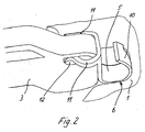
- the spring 6 is secured by means of two laterally engaging in detent openings 12 of the retaining clip 3 locking leg 11 on the mounting bracket 3.
- a bracket 10 which is supported on the rear wall of the receiving pocket 5 and in its width approximately corresponds to the associated width of the receiving pocket 5, so that the spring 6 and thus the headband 3 are locked on both sides.
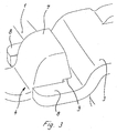
- the other, with the form-fitting holder 4 corresponding end of the retaining clip 3 is, as the figure shows very clearly 3, fork-shaped, while the form-fitting holder is formed as a bump 7 on the brake caliper 1, which has a groove 9 on its side facing the bracket 3 in which a part of the forked end of the retaining clip 3 rests.
- the design of the form-fitting holder 4 and the associated end of the retaining clip 3 may be provided for example in the form of a receptacle / pin. This shape is exclusively dependent on functional and manufacturing considerations.
Abstract
Description
Die vorliegende Erfmdung betrifft eine Scheibenbremse, insbesondere für ein Nutzfahrzeug entsprechend dem Oberbegriff des Anspruchs 1.The present invention relates to a disc brake, in particular for a commercial vehicle according to the preamble of
Eine solche Scheibenbremse ist beispielsweise aus der
Hierzu trägt auch bei, dass der Haltebügel mit einfachen Mitteln an- und abzubauen ist, wozu er einerseits in eine Ausnehmung des Bremssattels eingesteckt ist und andererseits mit dem Bremssattel, unter Überbrückung einer Einstecköffnung für die Bremsbacken durch Verschrauben fest verbunden ist.This is also helped by the fact that the headband is easy to assemble and disassemble, what it is on the one hand inserted into a recess of the caliper and on the other hand firmly connected to the caliper, by bridging an insertion for the brake shoes by screwing.
Bei dieser Scheibenbremse ist die taschenförmige Ausnehmung auf der Reaktionsseite, also auf der die Bremsenaußenseite bildenden Seite des Bremssattels vorgesehen, die einer im Bremssattel angeordneten Zuspanneinrichtung gegenüberliegt, die aktionsseitig an der der Fahrzeugmitte zugewandten Seite der Bremse angeordnet ist.In this disc brake, the pocket-shaped recess is provided on the reaction side, ie on the side of the brake caliper forming the brake outer side, which is opposite to an application device arranged in the caliper, which is arranged on the side of the brake facing the vehicle center.
Bei einer anderen bekannten Scheibenbremse ist die taschenförmige Ausnehmung auf der der Zuspanneinrichtung bzw. dem Aufnahmeraum dafür zugewandten Seite vorgesehen, wobei die Ausnehmung durch mechanische Bearbeitung eingebracht sein kann oder bei einer Herstellung des Bremssattels durch Gießen gleich mit angeformt wird.In another known disc brake, the pocket-shaped recess is provided on the side facing the application device or the receiving space for it, wherein the recess may be introduced by mechanical processing or is formed with a production of the caliper by casting equal with.
Das andere, der taschenförmigen Ausnehmung abgewandte Ende des Haltebügels ist mit dem Bremssattel verschraubt. Allerdings ist hierzu eine entsprechend aufwendige Bearbeitung erforderlich, wozu ein Bohren der Kernbohrung und ein anschließendes Gewindeschneiden gehört.The other, the pocket-shaped recess facing away from the end of the retaining clip is bolted to the caliper. However, this requires a correspondingly complex machining, including drilling the core bore and subsequent threading heard.
Da solche Scheibenbremsen in großen Stückzahlen hergestellt werden, stehen solche Arbeitsgänge einer optimierten Fertigung entgegen, so dass das Produkt insgesamt nur mit einem entsprechend hohen Aufwand herstellbar ist.Since such disc brakes are produced in large numbers, such operations are contrary to optimized production, so that the product can be produced in total only with a correspondingly high cost.
Dies gilt gleichermaßen für eine bekannte Ausführungsvariante, bei der der Haltebügel reaktionsseitig in ein Gussauge im Bremssattel eingesteckt ist, das eine Querbohrung zur Aufnahme aufweist, in die zur Befestigung des Haltebügels ein Bolzen, eine Scheibe oder ein Splint gesteckt wird.This applies equally to a known embodiment, in which the headband is inserted on the reaction side in a cast eye in the brake caliper, which has a transverse bore for receiving, in the fastening of the retaining clip a bolt, a disc or a split pin is inserted.
Die Vielzahl der dazu erforderlichen Teile steht einer optimierten Fertigung entgegen, wozu auch die Montage des Haltebügels zählt, die bislang relativ zeitaufwendig ist.The large number of parts required for this purpose precludes optimized production, which also includes the mounting of the retaining bracket, which has been relatively time consuming.
Der Erfindung liegt daher die Aufgabe zugrunde, eine Scheibenbremse der gattungsgemäßen Art so weiter zu entwickeln, dass sie kostengünstiger herstellbar ist und die Montage sowie Demontage der Bremsbacken einfacherer möglich ist.The invention is therefore based on the object to develop a disc brake of the generic type so that it is cheaper to produce and the assembly and disassembly of the brake shoes is simpler possible.
Diese Aufgabe wird durch eine Scheibenbremse mit den Merkmalen des Anspruchs 1 gelöst.This object is achieved by a disc brake with the features of
Durch die Erfmdung ist nun eine wesentlich einfachere Montage bzw. Demontage des Haltebügels und damit der Bremsbacken möglich, da der Haltebügel mit geringem Arbeitsaufwand einzusetzen bzw. zu entfernen ist.By Erfmdung now a much simpler assembly and disassembly of the retaining clip and thus the brake shoes is possible because the headband is to use with little effort or to remove.
Darüber hinaus stellt sich Herstellung der Scheibenbremse erheblich einfacherer dar, da nicht nur auf das zusätzliche Einbringen einer Gewindebohrung in den Bremssattel durch Einbringen einer Kernbohrung und Einschneiden eines Gewindes bzw. Einbringen einer Querbohrung verzichtet werden kann, sondern auch auf die Verwendung zusätzlicher Einzelteile, was gleichfalls zu einer Vereinfachung der Montage führt, neben einer Kostenreduzierung durch die Einsparung dieser Teile.In addition, production of the disc brake is considerably simpler, since not only the additional introduction of a threaded bore in the caliper by introducing a core hole and cutting a thread or introducing a transverse bore can be dispensed with, but also on the use of additional items, which also leads to a simplification of the assembly, in addition to a cost reduction by saving these parts.
Zur Federbelastung ist eine Feder beispielsweise in Form einer Blattfeder, Spiralfeder, Bügelfeder oder dergleichen vorgesehen, die in einer Aufnahme des Bremssattels weitgehend arretiert einliegt.For spring loading, a spring is provided for example in the form of a leaf spring, coil spring, bow spring or the like, which rests largely locked in a receptacle of the caliper.
Diese Feder ist vorzugsweise formschlüssig mit dem Haltebügel verbunden, beispielsweise durch Verrasten. Denkbar ist aber auch eine stoffschlüssige Verbindung, wie durch Verkleben, Verlöten oder Verschweißen.This spring is preferably positively connected to the headband, for example by locking. It is also conceivable, however, a cohesive connection, such as by gluing, soldering or welding.
Das gegenüberliegende Ende des Haltebügels, das erfindungsgemäß in einer Formschlusshalterung einliegt, kann gabelförmig ausgebildet sein und mit der daran angepassten Formschlusshalterung korrespondieren, wobei die Formschlusshalterung in einer bevorzugten Ausführungsform eine Nut aufweist, in der der Haltebügel in allen Richtungen fixiert einliegt.The opposite end of the retaining clip, which rests according to the invention in a form-fitting holder may be fork-shaped and correspond with the adapted form-fitting holder, wherein the form-fitting holder in a preferred embodiment has a groove in which the headband is fixed fixed in all directions.
Die Formschlusshalterung ebenso wie die Aufnahmetasche sind ohne eine mechanische Bearbeitung herstellbar, insbesondere dann, wenn der Bremssattel, an dem der Haltebügel beidseitig festgelegt ist, als Gussteil ausgebildet wird.The positive locking holder as well as the receiving pocket can be produced without mechanical processing, in particular when the caliper, on which the headband is fixed on both sides, is designed as a cast part.
Daneben zeichnet sich die neue Verbindung Haltebügel/Bremssattel durch ihren geringen Platzbedarf aus, wie er im Stand der Technik zum Eindrehen der Schraube bzw. der Stifte oder Splinte in die Querbohrung erforderlich ist.In addition, the new connection headband / brake caliper is characterized by its small footprint, as required in the prior art for screwing the screw or the pins or split pins in the transverse bore.
Die Montage des Haltebügels erfolgt in der Form, dass zunächst das mit der Feder bestückte Ende des Haltebügels in die Aufnahmetasche eindrückt wird, unter Zusammendrücken der Feder, wobei das andere Ende des Haltebügels frei liegt und in die Formschlusshalterung eingesetzt werden kann. Nach einem Loslassen des Haltebügels wird dieser durch die Kraft der Feder gegen die Formschlusshalterung gedrückt, so dass die erwähnte Fixierung in alle Richtungen gegeben ist.The mounting of the retaining clip takes place in the form that initially the spring-loaded end of the retaining clip is pressed into the receiving pocket, with compression of the spring, wherein the other end of the retaining clip is exposed and can be inserted into the positive locking mount. After releasing the retaining clip that is pressed by the force of the spring against the form-fitting holder, so that the aforementioned fixation is given in all directions.
Weitere vorteilhafte Ausbildungen der Erfmdung sind in den Unteransprüchen gekennzeichnet.Further advantageous embodiments of the invention are characterized in the subclaims.
Ein Ausführungsbeispiel der Erfindung wird nachfolgend anhand der beigefügten Zeichnungen beschrieben.An embodiment of the invention will be described below with reference to the accompanying drawings.
Es zeigen:
Figur 1- einen Teil einer erfindungsgemäßen Scheibenbremse in einer perspektivischen geschnittenen Seitenansicht
- Figur 2
- eine Einzelheit der Scheibenbremse in einer perspektivischen Ansicht
Figur 3- eine andere Einzelheit der Scheibenbremse, ebenfalls in einer perspektivischen Ansicht
Figur 4- einen Schnitt durch die Einzelheit nach
Figur 3
- FIG. 1
- a part of a disc brake according to the invention in a perspective sectional side view
- FIG. 2
- a detail of the disc brake in a perspective view
- FIG. 3
- another detail of the disc brake, also in a perspective view
- FIG. 4
- a section through the detail of Figure 3
In der Figur 1 ist ein Teil einer Scheibenbremse, insbesondere für ein Nutzfahrzeug dargestellt, mit einem Bremssattel 1, der einen Aufnahmeraum 2 für eine nicht dargestellte Zuspanneinrichtung aufweist und in den eine mit Bremsbacken in Wirkverbindung bringbare Bremsscheibe montierbar ist, wobei der Bremssattel 1 an einem fahrzeugsseitigen Bremsträger befestigbar ist.In the figure 1 is a part of a disc brake, in particular for a commercial vehicle, shown with a
An dem Bremssattel 1 ist ein Haltebügel 3 lösbar befestigt, der eine Einführöffnung zum Einbringen der Bremsbacken überspannt und als Niederhalter für ebenfalls nicht dargestellte Federn dient, die auf die Außenkanten der Bremsbacken einwirken.On the
In dem dem Aufnahmeraum 2 benachbarten Bereich ist der Haltebügel 3 in eine im Bremssattel 1 vorgesehene Aufnahmetasche 5 eingesteckt, während das gegenüberliegende Ende des Haltebügels 3 mit einer am Bremssattel 1 angeformten Formschlusshalterung 4 korrespondiert.In the area adjacent to the receiving space 2, the
An dem in die Aufnahmetasche 5 eingesteckten Ende des Haltebügels 3 ist eine Feder 6 angeschlossen, die besonders deutlich in der Figur 2 zu erkennen ist.At the inserted into the receiving
Dort ist zu sehen, dass die Feder 6 mittels zweier seitlich in Rastöffnungen 12 des Haltebügels 3 eingreifender Rastschenkel 11 am Haltebügel 3 befestigt ist.There it can be seen that the
Stirnseitig des Haltebügels 3 erstreckt sich ein Bügel 10, der sich an der Rückwand der Aufnahmetasche 5 abstützt und in seiner Breite etwa der zugeordneten Breite der Aufnahmetasche 5 entspricht, so dass die Feder 6 und damit der Haltebügel 3 beidseitig arretiert sind.The front side of the
Das andere, mit der Formschlusshalterung 4 korrespondierende Ende des Haltebügels 3 ist, wie die Figur 3 sehr deutlich zeigt, gabelförmig ausgebildet, während die Formschlusshalterung als Höcker 7 an den Bremssattel 1 angeformt ist, der auf seiner dem Haltebügel 3 zugewandten Seite eine Nut 9 aufweist, in der ein Teil des gabelförmigen Endes des Haltebügels 3 einliegt.The other, with the form-
An den quer dazu verlaufenden Seiten des Höckers 7 liegen zwei parallel und mit Abstand zueinander verlaufende Zinken 8 an, so dass der über den Druck der Feder 6 gegen den Höcker 7 gedrückte Haltebügel 3 in jeder Richtung fixiert ist.At the transverse thereto extending sides of the
Die Einlagerung des gabelförmigen Endes des Haltebügels 3 in der Nut 9 ist in der Figur 4 als Einzelheit gezeigt. Dort ist auch zu erkennen, dass die Dicke des in der Nut 9 einliegenden Haltebügels 3 etwa der zugeordneten Höhe der Nut 9 entspricht bzw. geringfügig kleiner ist.The storage of the forked end of the
Zur Montage des Haltebügels 3 wird dieser mit dem federseitigen Ende in die Aufnahmetasche 5 geführt und unter Deformierung des Bügels 10 der Feder 6 so weit eingeschoben, bis das andere Ende über den Höcker 7 geführt werden kann bis in den Bereich der Nut 9. Nach einem Entlasten der Feder 6 durch Loslassen des Haltebügels 3 wird dieser mit seinem gabelförmigen Ende in die Nut 9 des Höckers 7 gedrückt, wo er federbelastet dauerhaft und fixiert einliegt. Ein Lösen des Haltebügels 3 erfolgt in umgekehrter Reihenfolge.For mounting the
Anstelle des gezeigten Ausführungsbeispieles sowohl hinsichtlich der Ausbildung der Feder 6 wie auch hinsichtlich der Ausbildung des gegenüberliegenden mit der Formschlusshalterung 4 korrespondierenden Endes sind selbstverständlich auch andere Konfigurationen möglich, beispielsweise als Feder in Form von Spiralfedern, Tellerfedern, Blattfedern oder dergleichen.Of course, other configurations are possible, for example as a spring in the form of coil springs, disc springs, leaf springs or the like in place of the embodiment shown both in terms of the design of the
Die Ausgestaltung der Formschlusshalterung 4 und des zugeordneten Endes des Haltebügels 3 kann beispielsweise in Form einer Aufnahme/Zapfen vorgesehen sein. Diese Formgebung ist ausschließlich abhängig von funktionalen und fertigungstechnischen Überlegungen.The design of the form-
- 11
- Bremssattelcaliper
- 22
- Aufnahmeraumaccommodation space
- 33
- Haltebügelheadband
- 44
- FormschlusshalterungForm-fit holder
- 55
- Aufnahmetaschereceiving pocket
- 66
- Federfeather
- 77
- Höckercusp
- 88th
- Zinkenprong
- 99
- Nutgroove
- 1010
- Bügelhanger
- 1111
- Rastschenkellatching leg
- 1212
- Rastöffnunglatching opening
Claims (13)
Applications Claiming Priority (1)
| Application Number | Priority Date | Filing Date | Title |
|---|---|---|---|
| DE200510045877 DE102005045877B3 (en) | 2005-09-26 | 2005-09-26 | Disk brake for commercial vehicle, has mounting bracket that extends in axial direction of disk, is spring loaded in longitudinal axial direction and lies in form fit retainer, and spring that is supported at mounting bracket |
Publications (2)
| Publication Number | Publication Date |
|---|---|
| EP1767805A2 true EP1767805A2 (en) | 2007-03-28 |
| EP1767805A3 EP1767805A3 (en) | 2008-06-25 |
Family
ID=37635881
Family Applications (1)
| Application Number | Title | Priority Date | Filing Date |
|---|---|---|---|
| EP06019970A Withdrawn EP1767805A3 (en) | 2005-09-26 | 2006-09-25 | Disc brake, in particular for a utility vehicle |
Country Status (2)
| Country | Link |
|---|---|
| EP (1) | EP1767805A3 (en) |
| DE (1) | DE102005045877B3 (en) |
Cited By (6)
| Publication number | Priority date | Publication date | Assignee | Title |
|---|---|---|---|---|
| WO2008022770A1 (en) | 2006-08-22 | 2008-02-28 | Knorr-Bremse Systeme für Nutzfahrzeuge GmbH | Disc brake, in particular for a commercial vehicle |
| DE202008013446U1 (en) | 2008-10-09 | 2009-04-09 | Haldex Brake Products Ab | Disc brake and retaining bracket and locking device for pad retaining springs therefor |
| EP2997279B1 (en) | 2013-05-13 | 2018-08-01 | WABCO Europe BVBA | Caliper disc brake of a vehicle, in particular of a commercial vehicle, and brake caliper of such a brake |
| EP2997278B1 (en) | 2013-05-13 | 2018-08-15 | WABCO Europe BVBA | Caliper disc brake of a vehicle, in particular a commercial vehicle, and holding-down device of such a brake |
| EP3828433B1 (en) | 2017-04-18 | 2022-08-10 | BPW Bergische Achsen KG | Flat spring of a hold-down assembly for the brake pads of a disc brake |
| WO2023247704A1 (en) | 2022-06-23 | 2023-12-28 | Haldex Brake Products Ab | Disk brake, securing elements and retaining bracket therefor |
Families Citing this family (10)
| Publication number | Priority date | Publication date | Assignee | Title |
|---|---|---|---|---|
| DE102006002306B4 (en) * | 2006-01-18 | 2015-08-13 | Knorr-Bremse Systeme für Nutzfahrzeuge GmbH | Disc brake, in particular for a commercial vehicle |
| DE102012003109B4 (en) * | 2012-02-16 | 2014-01-23 | Knorr-Bremse Systeme für Nutzfahrzeuge GmbH | Disc brake for a commercial vehicle |
| DE102012109783A1 (en) * | 2012-10-15 | 2014-04-17 | Knorr-Bremse Systeme für Nutzfahrzeuge GmbH | Arrangement of a pad retaining bracket on the caliper of a disc brake |
| DE102014107227B4 (en) | 2014-03-14 | 2016-02-04 | Knorr-Bremse Systeme für Nutzfahrzeuge GmbH | Disc brake with pad retainer and safety device, and brake pad set |
| DE102015111847A1 (en) | 2015-07-22 | 2017-01-26 | Knorr-Bremse Systeme für Nutzfahrzeuge GmbH | Pad retainer mounting tool with disc brake locking device, disc brake and brake pad set |
| DE102015118291A1 (en) | 2015-10-27 | 2017-04-27 | Bpw Bergische Achsen Kg | Disc brake, as well as leaf spring of a hold-down arrangement for the brake pads of a disc brake |
| DE102015118838A1 (en) * | 2015-11-03 | 2017-05-04 | Knorr-Bremse Systeme für Nutzfahrzeuge GmbH | Disc brake with pad retainer and safety device, and brake pad set |
| DE102015122558A1 (en) | 2015-12-22 | 2017-06-22 | Bpw Bergische Achsen Kg | Disc brake and hold-down for attaching brake pads in a disc brake |
| DE102017100688B4 (en) | 2017-01-16 | 2021-06-24 | Saf-Holland Gmbh | Device for fixing a brake shoe, braking device and method for fixing a brake shoe |
| DE102017113384A1 (en) | 2017-06-19 | 2018-12-20 | Knorr-Bremse Systeme für Nutzfahrzeuge GmbH | Disc brake with a pad retention system, and brake pad set |
Citations (1)
| Publication number | Priority date | Publication date | Assignee | Title |
|---|---|---|---|---|
| DE8615015U1 (en) | 1986-06-04 | 1987-10-01 | Lucas Industries P.L.C., Birmingham, West Midlands, Gb |
Family Cites Families (9)
| Publication number | Priority date | Publication date | Assignee | Title |
|---|---|---|---|---|
| DE1775586B1 (en) * | 1968-08-29 | 1970-10-22 | Teves Gmbh Alfred | Retaining plate for brake shoes of partially lined disc brakes |
| DE1928991C3 (en) * | 1969-06-07 | 1981-06-25 | Alfred Teves Gmbh, 6000 Frankfurt | Brake shoe holder for disc brakes |
| GB1491903A (en) * | 1974-04-02 | 1977-11-16 | Girling Ltd | Disc brakes for vehicles |
| JPS5423865A (en) * | 1977-07-25 | 1979-02-22 | Sumitomo Electric Ind Ltd | Locking device of pin |
| DE3244790A1 (en) * | 1982-12-03 | 1984-06-07 | Alfred Teves Gmbh, 6000 Frankfurt | Spot-type disc brake, in particular for motor vehicles |
| DE9406166U1 (en) * | 1994-04-14 | 1994-06-01 | Bergische Achsen Kotz Soehne | Device for holding the brake pad carrier of a disc brake |
| EP0703378B1 (en) * | 1994-09-22 | 2001-12-05 | Meritor Heavy Vehicle Technology, LLC | Disc brake friction pad and retention system |
| DE19849309B4 (en) * | 1998-10-26 | 2010-09-09 | Knorr-Bremse Systeme für Nutzfahrzeuge GmbH | Disc brake for a commercial vehicle |
| DE10302332B3 (en) * | 2003-01-22 | 2004-03-25 | Knorr-Bremse Systeme für Nutzfahrzeuge GmbH | Disc brake for commercial motor vehicle has sliding closure plate with ring to receive end of releasable retaining stirrup for pads |
-
2005
- 2005-09-26 DE DE200510045877 patent/DE102005045877B3/en active Active
-
2006
- 2006-09-25 EP EP06019970A patent/EP1767805A3/en not_active Withdrawn
Patent Citations (1)
| Publication number | Priority date | Publication date | Assignee | Title |
|---|---|---|---|---|
| DE8615015U1 (en) | 1986-06-04 | 1987-10-01 | Lucas Industries P.L.C., Birmingham, West Midlands, Gb |
Cited By (7)
| Publication number | Priority date | Publication date | Assignee | Title |
|---|---|---|---|---|
| WO2008022770A1 (en) | 2006-08-22 | 2008-02-28 | Knorr-Bremse Systeme für Nutzfahrzeuge GmbH | Disc brake, in particular for a commercial vehicle |
| DE202008013446U1 (en) | 2008-10-09 | 2009-04-09 | Haldex Brake Products Ab | Disc brake and retaining bracket and locking device for pad retaining springs therefor |
| EP2997279B1 (en) | 2013-05-13 | 2018-08-01 | WABCO Europe BVBA | Caliper disc brake of a vehicle, in particular of a commercial vehicle, and brake caliper of such a brake |
| EP2997278B1 (en) | 2013-05-13 | 2018-08-15 | WABCO Europe BVBA | Caliper disc brake of a vehicle, in particular a commercial vehicle, and holding-down device of such a brake |
| EP2997278B2 (en) † | 2013-05-13 | 2022-07-20 | ZF CV Systems Europe BV | Caliper disc brake of a vehicle |
| EP3828433B1 (en) | 2017-04-18 | 2022-08-10 | BPW Bergische Achsen KG | Flat spring of a hold-down assembly for the brake pads of a disc brake |
| WO2023247704A1 (en) | 2022-06-23 | 2023-12-28 | Haldex Brake Products Ab | Disk brake, securing elements and retaining bracket therefor |
Also Published As
| Publication number | Publication date |
|---|---|
| EP1767805A3 (en) | 2008-06-25 |
| DE102005045877B3 (en) | 2007-02-15 |
Similar Documents
| Publication | Publication Date | Title |
|---|---|---|
| DE102005045877B3 (en) | Disk brake for commercial vehicle, has mounting bracket that extends in axial direction of disk, is spring loaded in longitudinal axial direction and lies in form fit retainer, and spring that is supported at mounting bracket | |
| EP1764527B1 (en) | Disc brake | |
| EP3359843B1 (en) | Disc brake for a commercial vehicle | |
| EP2057384B1 (en) | Disc brake, in particular for a commercial vehicle | |
| EP1832777B1 (en) | Disc brake | |
| DE102006002306B4 (en) | Disc brake, in particular for a commercial vehicle | |
| EP2050980B1 (en) | Brake cover holder on a disk brake and brake cover | |
| DE202008013446U1 (en) | Disc brake and retaining bracket and locking device for pad retaining springs therefor | |
| DE102013011673B4 (en) | Brake pad holder of a disc brake | |
| DE102005052437B4 (en) | Disc brake, in particular for a commercial vehicle, and retaining bracket for mounting brake pads of the disc brake | |
| DE102005049057B4 (en) | Disc brake, in particular for a commercial vehicle | |
| DE102012108670A1 (en) | Pneumatically or electromechanically actuated disc brake | |
| EP3724532A1 (en) | Disc brake for a utility vehicle, and brake pad set | |
| DE102005059247B4 (en) | braking device | |
| EP1798437A1 (en) | Brake lining holding device | |
| DE102004042576A1 (en) | Disc brake for a vehicle, in particular a commercial vehicle | |
| DE102014106090B4 (en) | Brake pad holder of a disc brake | |
| DE102013011671B4 (en) | Brake pad holder of a disc brake | |
| DE202006021291U1 (en) | Disc brake, in particular for a commercial vehicle | |
| EP2824352B1 (en) | Brake lining mount of a disc brake for a commercial vehicle | |
| DE202015105977U1 (en) | Disc brake for a commercial vehicle | |
| EP2092846B1 (en) | Table | |
| DE102006031066B3 (en) | Disc brake, in particular for a commercial vehicle and brake pad for a disc brake | |
| WO2017036579A1 (en) | Torque wrench | |
| DE102006031057B3 (en) | Disk brake for a commercial vehicle comprises a locking element arranged in a caliper under an acute angle |
Legal Events
| Date | Code | Title | Description |
|---|---|---|---|
| PUAI | Public reference made under article 153(3) epc to a published international application that has entered the european phase |
Free format text: ORIGINAL CODE: 0009012 |
|
| AK | Designated contracting states |
Kind code of ref document: A2 Designated state(s): AT BE BG CH CY CZ DE DK EE ES FI FR GB GR HU IE IS IT LI LT LU LV MC NL PL PT RO SE SI SK TR |
|
| AX | Request for extension of the european patent |
Extension state: AL BA HR MK YU |
|
| RIN1 | Information on inventor provided before grant (corrected) |
Inventor name: HAERTL, THOMAS Inventor name: SPRINGER, MARIO |
|
| PUAL | Search report despatched |
Free format text: ORIGINAL CODE: 0009013 |
|
| AK | Designated contracting states |
Kind code of ref document: A3 Designated state(s): AT BE BG CH CY CZ DE DK EE ES FI FR GB GR HU IE IS IT LI LT LU LV MC NL PL PT RO SE SI SK TR |
|
| AX | Request for extension of the european patent |
Extension state: AL BA HR MK RS |
|
| 17P | Request for examination filed |
Effective date: 20081229 |
|
| AKX | Designation fees paid |
Designated state(s): AT BE BG CH CY CZ DE DK EE ES FI FR GB GR HU IE IS IT LI LT LU LV MC NL PL PT RO SE SI SK TR |
|
| 17Q | First examination report despatched |
Effective date: 20090210 |
|
| STAA | Information on the status of an ep patent application or granted ep patent |
Free format text: STATUS: THE APPLICATION IS DEEMED TO BE WITHDRAWN |
|
| 18D | Application deemed to be withdrawn |
Effective date: 20090623 |