EP1767309A1 - Methods and apparatus for manufacturing components - Google Patents
Methods and apparatus for manufacturing components Download PDFInfo
- Publication number
- EP1767309A1 EP1767309A1 EP06254842A EP06254842A EP1767309A1 EP 1767309 A1 EP1767309 A1 EP 1767309A1 EP 06254842 A EP06254842 A EP 06254842A EP 06254842 A EP06254842 A EP 06254842A EP 1767309 A1 EP1767309 A1 EP 1767309A1
- Authority
- EP
- European Patent Office
- Prior art keywords
- assembly
- drive
- coupled
- fixture
- platens
- Prior art date
- Legal status (The legal status is an assumption and is not a legal conclusion. Google has not performed a legal analysis and makes no representation as to the accuracy of the status listed.)
- Granted
Links
- 238000004519 manufacturing process Methods 0.000 title claims abstract description 35
- 238000000034 method Methods 0.000 title abstract description 14
- 230000008878 coupling Effects 0.000 claims abstract description 15
- 238000010168 coupling process Methods 0.000 claims abstract description 15
- 238000005859 coupling reaction Methods 0.000 claims abstract description 15
- 239000007921 spray Substances 0.000 claims description 10
- 230000007246 mechanism Effects 0.000 claims description 4
- 238000000576 coating method Methods 0.000 description 20
- 239000011248 coating agent Substances 0.000 description 19
- 238000005507 spraying Methods 0.000 description 7
- 230000008021 deposition Effects 0.000 description 3
- 238000009434 installation Methods 0.000 description 2
- 230000004048 modification Effects 0.000 description 2
- 238000012986 modification Methods 0.000 description 2
- 230000010355 oscillation Effects 0.000 description 2
- 230000008569 process Effects 0.000 description 2
- 230000008859 change Effects 0.000 description 1
- 230000002708 enhancing effect Effects 0.000 description 1
- 239000012530 fluid Substances 0.000 description 1
- 238000007689 inspection Methods 0.000 description 1
- 239000011253 protective coating Substances 0.000 description 1
- 230000008439 repair process Effects 0.000 description 1
Images


Classifications
-
- B—PERFORMING OPERATIONS; TRANSPORTING
- B23—MACHINE TOOLS; METAL-WORKING NOT OTHERWISE PROVIDED FOR
- B23Q—DETAILS, COMPONENTS, OR ACCESSORIES FOR MACHINE TOOLS, e.g. ARRANGEMENTS FOR COPYING OR CONTROLLING; MACHINE TOOLS IN GENERAL CHARACTERISED BY THE CONSTRUCTION OF PARTICULAR DETAILS OR COMPONENTS; COMBINATIONS OR ASSOCIATIONS OF METAL-WORKING MACHINES, NOT DIRECTED TO A PARTICULAR RESULT
- B23Q1/00—Members which are comprised in the general build-up of a form of machine, particularly relatively large fixed members
- B23Q1/25—Movable or adjustable work or tool supports
- B23Q1/44—Movable or adjustable work or tool supports using particular mechanisms
- B23Q1/50—Movable or adjustable work or tool supports using particular mechanisms with rotating pairs only, the rotating pairs being the first two elements of the mechanism
- B23Q1/54—Movable or adjustable work or tool supports using particular mechanisms with rotating pairs only, the rotating pairs being the first two elements of the mechanism two rotating pairs only
- B23Q1/5406—Movable or adjustable work or tool supports using particular mechanisms with rotating pairs only, the rotating pairs being the first two elements of the mechanism two rotating pairs only a single rotating pair followed perpendicularly by a single rotating pair
- B23Q1/5437—Movable or adjustable work or tool supports using particular mechanisms with rotating pairs only, the rotating pairs being the first two elements of the mechanism two rotating pairs only a single rotating pair followed perpendicularly by a single rotating pair and in which the degree of freedom, which belongs to the working surface, is perpendicular to this surface
-
- B—PERFORMING OPERATIONS; TRANSPORTING
- B23—MACHINE TOOLS; METAL-WORKING NOT OTHERWISE PROVIDED FOR
- B23P—METAL-WORKING NOT OTHERWISE PROVIDED FOR; COMBINED OPERATIONS; UNIVERSAL MACHINE TOOLS
- B23P19/00—Machines for simply fitting together or separating metal parts or objects, or metal and non-metal parts, whether or not involving some deformation; Tools or devices therefor so far as not provided for in other classes
- B23P19/10—Aligning parts to be fitted together
-
- B—PERFORMING OPERATIONS; TRANSPORTING
- B23—MACHINE TOOLS; METAL-WORKING NOT OTHERWISE PROVIDED FOR
- B23P—METAL-WORKING NOT OTHERWISE PROVIDED FOR; COMBINED OPERATIONS; UNIVERSAL MACHINE TOOLS
- B23P19/00—Machines for simply fitting together or separating metal parts or objects, or metal and non-metal parts, whether or not involving some deformation; Tools or devices therefor so far as not provided for in other classes
-
- C—CHEMISTRY; METALLURGY
- C23—COATING METALLIC MATERIAL; COATING MATERIAL WITH METALLIC MATERIAL; CHEMICAL SURFACE TREATMENT; DIFFUSION TREATMENT OF METALLIC MATERIAL; COATING BY VACUUM EVAPORATION, BY SPUTTERING, BY ION IMPLANTATION OR BY CHEMICAL VAPOUR DEPOSITION, IN GENERAL; INHIBITING CORROSION OF METALLIC MATERIAL OR INCRUSTATION IN GENERAL
- C23C—COATING METALLIC MATERIAL; COATING MATERIAL WITH METALLIC MATERIAL; SURFACE TREATMENT OF METALLIC MATERIAL BY DIFFUSION INTO THE SURFACE, BY CHEMICAL CONVERSION OR SUBSTITUTION; COATING BY VACUUM EVAPORATION, BY SPUTTERING, BY ION IMPLANTATION OR BY CHEMICAL VAPOUR DEPOSITION, IN GENERAL
- C23C4/00—Coating by spraying the coating material in the molten state, e.g. by flame, plasma or electric discharge
-
- Y—GENERAL TAGGING OF NEW TECHNOLOGICAL DEVELOPMENTS; GENERAL TAGGING OF CROSS-SECTIONAL TECHNOLOGIES SPANNING OVER SEVERAL SECTIONS OF THE IPC; TECHNICAL SUBJECTS COVERED BY FORMER USPC CROSS-REFERENCE ART COLLECTIONS [XRACs] AND DIGESTS
- Y10—TECHNICAL SUBJECTS COVERED BY FORMER USPC
- Y10T—TECHNICAL SUBJECTS COVERED BY FORMER US CLASSIFICATION
- Y10T29/00—Metal working
- Y10T29/49—Method of mechanical manufacture
- Y10T29/49826—Assembling or joining
- Y10T29/49828—Progressively advancing of work assembly station or assembled portion of work
-
- Y—GENERAL TAGGING OF NEW TECHNOLOGICAL DEVELOPMENTS; GENERAL TAGGING OF CROSS-SECTIONAL TECHNOLOGIES SPANNING OVER SEVERAL SECTIONS OF THE IPC; TECHNICAL SUBJECTS COVERED BY FORMER USPC CROSS-REFERENCE ART COLLECTIONS [XRACs] AND DIGESTS
- Y10—TECHNICAL SUBJECTS COVERED BY FORMER USPC
- Y10T—TECHNICAL SUBJECTS COVERED BY FORMER US CLASSIFICATION
- Y10T29/00—Metal working
- Y10T29/49—Method of mechanical manufacture
- Y10T29/49826—Assembling or joining
- Y10T29/49828—Progressively advancing of work assembly station or assembled portion of work
- Y10T29/49829—Advancing work to successive stations [i.e., assembly line]
-
- Y—GENERAL TAGGING OF NEW TECHNOLOGICAL DEVELOPMENTS; GENERAL TAGGING OF CROSS-SECTIONAL TECHNOLOGIES SPANNING OVER SEVERAL SECTIONS OF THE IPC; TECHNICAL SUBJECTS COVERED BY FORMER USPC CROSS-REFERENCE ART COLLECTIONS [XRACs] AND DIGESTS
- Y10—TECHNICAL SUBJECTS COVERED BY FORMER USPC
- Y10T—TECHNICAL SUBJECTS COVERED BY FORMER US CLASSIFICATION
- Y10T29/00—Metal working
- Y10T29/49—Method of mechanical manufacture
- Y10T29/49998—Work holding
-
- Y—GENERAL TAGGING OF NEW TECHNOLOGICAL DEVELOPMENTS; GENERAL TAGGING OF CROSS-SECTIONAL TECHNOLOGIES SPANNING OVER SEVERAL SECTIONS OF THE IPC; TECHNICAL SUBJECTS COVERED BY FORMER USPC CROSS-REFERENCE ART COLLECTIONS [XRACs] AND DIGESTS
- Y10—TECHNICAL SUBJECTS COVERED BY FORMER USPC
- Y10T—TECHNICAL SUBJECTS COVERED BY FORMER US CLASSIFICATION
- Y10T29/00—Metal working
- Y10T29/53—Means to assemble or disassemble
- Y10T29/53313—Means to interrelatedly feed plural work parts from plural sources without manual intervention
-
- Y—GENERAL TAGGING OF NEW TECHNOLOGICAL DEVELOPMENTS; GENERAL TAGGING OF CROSS-SECTIONAL TECHNOLOGIES SPANNING OVER SEVERAL SECTIONS OF THE IPC; TECHNICAL SUBJECTS COVERED BY FORMER USPC CROSS-REFERENCE ART COLLECTIONS [XRACs] AND DIGESTS
- Y10—TECHNICAL SUBJECTS COVERED BY FORMER USPC
- Y10T—TECHNICAL SUBJECTS COVERED BY FORMER US CLASSIFICATION
- Y10T29/00—Metal working
- Y10T29/53—Means to assemble or disassemble
- Y10T29/53313—Means to interrelatedly feed plural work parts from plural sources without manual intervention
- Y10T29/53365—Multiple station assembly apparatus
-
- Y—GENERAL TAGGING OF NEW TECHNOLOGICAL DEVELOPMENTS; GENERAL TAGGING OF CROSS-SECTIONAL TECHNOLOGIES SPANNING OVER SEVERAL SECTIONS OF THE IPC; TECHNICAL SUBJECTS COVERED BY FORMER USPC CROSS-REFERENCE ART COLLECTIONS [XRACs] AND DIGESTS
- Y10—TECHNICAL SUBJECTS COVERED BY FORMER USPC
- Y10T—TECHNICAL SUBJECTS COVERED BY FORMER US CLASSIFICATION
- Y10T29/00—Metal working
- Y10T29/53—Means to assemble or disassemble
- Y10T29/53313—Means to interrelatedly feed plural work parts from plural sources without manual intervention
- Y10T29/5337—Means to interrelatedly feed plural work parts from plural sources without manual intervention including assembly pallet
Definitions
- the present invention relates generally to manufacturing components, and more specifically to methods and apparatus for aligning, supporting, and/or securing components for manufacture.
- Accurate manufacturing of gas turbine engine components may be a significant factor in determining both manufacturing timing and cost.
- accurate manufacturing of the blade may be a significant factor affecting an overall cost of fabrication of the gas turbine engine, as well as subsequent modifications, repairs, and inspections of the blade.
- at least some known gas turbine engine blades receive a protective coating to facilitate protection of the turbine blades when the blades are subjected to high velocity fluid flows in a high temperature environment. Accurately coating the turbine blades facilitates enhancing a useful life of the blades.
- known systems To align a turbine blade for spray coating, known systems enable a single blade to be coupled to a positioning system to enable a spray coating to be applied to the blade. At least some known positioning systems require the blades be repositioned several times through a variety of orientations to enable the coating to be applied at the desired thickness across each portion of the blade to be coated. The process is then repeated for each blade requiring a coating. As such, applying a coating to a component using known systems may be a time consuming process that increases engine manufacturing cycle times and fabrication costs.
- a method for manufacturing components includes coupling a drive assembly to a positioning assembly, coupling a plurality of components to be manufactured to a plurality of fixtures, securing the plurality of fixtures to the drive assembly wherein each fixture is configured to receive a component to be manufactured, and repositioning the plurality of components simultaneously using the positioning assembly to facilitate manufacturing of the plurality of components, wherein the components are configured to be oscillated in a first plane of rotation via the drive assembly and rotated through a second plane of rotation via the plurality of fixtures.
- a fixture assembly for use in manufacturing a plurality of components.
- the fixture assembly includes at least two fixtures configured to support the plurality of components being manufactured, a drive assembly, the at least two fixtures coupled to the drive assembly and rotatable along a first axis of rotation, the drive assembly comprises a plurality of spindles extending outward therefrom and a plurality of platens coupled to the spindles, the plurality of spindles and the plurality of platens configured to oscillate in a second plane of rotation that is orthogonal to the first axis of rotation.
- a coating system in a further aspect, includes a drive assembly, a fixture assembly comprising at least two fixtures coupled to the drive assembly, and a positioning assembly coupled to the fixture assembly, the drive assembly comprises a plurality of spindles extending outward therefrom and a plurality of platens coupled to the spindles, the plurality of spindles and the plurality of platens configured to oscillate in a second plane of rotation that is orthogonal to the first axis of rotation.
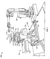
- Figure 1 is a perspective view of an exemplary embodiment of a component spray coating system 100 in a first position.
- system 100 is used to spray turbine blades 112.
- System 100 includes a coating applicator 104 having a spray nozzle 105, a component manufacturing apparatus 102 that includes a fixture assembly 106, and a positioning and coating control system (not shown on Figure 1).
- fixture assembly 106 is rotated towards coating applicator 104 and is coupled to a positioning assembly 108.
- Fixture assembly 106 includes a plurality of fixtures 110 used to secure the components. More specifically, in the exemplary embodiment, assembly 106 includes four fixtures 110 which enable four turbine blades 112 to be coated simultaneously as described in more detail below. In an alternative embodiment, assembly 106 includes any number of a plurality of fixtures 110. Turbine blades 112 are shown for illustrative purposes only and fixture assembly 106 is not limited to only being used in the manufacture of blades 112. Fixture 110 is securely coupled to a respective one of a plurality of platens 114. The exemplary embodiment includes four platens 114 that each cooperate with a respective fixture 110. Platens 114 are each coupled to a drive assembly 116.
- Drive assembly 116 includes an enclosure 117 that contains a plurality of drive gears (not shown in Figure 1) coupled to a plurality of spindles (not shown in Figure 1) and platens 114.
- Spindles (not shown in Figure 1) extend outwardly from assembly 116, and the plurality of drive gears are sized, positioned, and aligned to enable each spindle and platen 114 rotate at substantially the same rate.
- Drive assembly 116 includes a mounting frame 119 and a plurality of lifting slots 121 that are formed integrally with mounting frame 119.
- the arrows labeled J8 on Figure 1 illustrate a plane of rotation and a direction of rotation of platens 114.
- Drive assembly 116 also houses a plurality of upper bearings (not shown in Figure 1), a plurality of platen-to-spindle biased couplings (not shown in Figure 1), a plurality of collars (not shown in Figure 1), a main drive gear (not shown in Figure 1), a plurality of platen drive gears (not shown in Figure 1), a plurality of inter-platen drive gears (not shown in Figure 1), a main drive gear drive shaft (not shown in Figure 1), and a plurality of lower bearings (not shown in Figure 1).
- positioning assembly 108 is a turntable that has been modified and that includes a plurality of floor supports 122, a tilt drive electric motor 124, a tilt drive shaft and support bearing (not shown in Figure 1), a platen drive motor 126, a platen drive translational gear 128, a plurality of electric power cables 130, and a raised floor stand 132.
- Assembly 108 also includes a platen drive shaft-to-main drive gear drive shaft coupling (not shown in Figure 1) through which assembly 108 powers drive assembly 116.
- the arrows labeled J7 illustrate a tilt plane of rotation and a direction of rotation of assembly 106.
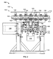
- FIG. 2 is a schematic of an end view of a component manufacturing apparatus 102 used with coating system 100.
- assembly 102 also includes a plurality of upper bearings 150, a plurality of collars 152, a main drive gear 154, a plurality of platen drive gears 156, a plurality of inter-platen drive gears 158, a plurality of inter-platen drive gear shafts 159, a main drive gear drive shaft 160, a plurality of lower bearings 162, a platen drive shaft 164, a drive assembly-to-positioning assembly coupling 166, a tilt drive shaft 168, a tilt drive shaft bearing 170 and a tilt axis of rotation 172.
- Bearing 170 supports tilt drive shaft 168.
- a platen drive shaft-to-main drive gear drive shaft coupling (not shown in Figure 2) rotatably coupled to drive shaft 164 to drive shaft 160.
- Platen drive electric motor 126 is coupled to platen drive shaft 164 via translational gear 128.
- Gear 128 receives input from motor 126 and causes drive shaft 164 to rotate in a plane of rotation that is orthogonal to tilt axis of rotation 172. More specifically, in the exemplary embodiment, the rotation may be in a clockwise or counterclockwise direction, or the motor 126 may cause oscillation between the two rotational directions.
- Drive shaft 164 is rotatably coupled to main drive gear drive shaft 160 via platen drive shaft-to-main drive gear drive shaft coupling (not shown in Figure 2) and rotation is induced to drive shaft 160 from drive shaft 164.
- Drive shaft 160 subsequently rotates main drive gear 154 which causes rotation of two adjacent platen drive gears 156.
- Gears 156 transmit rotation to inter-plated drive gears 158 located adjacent to gears 156.
- Gears 158 transmit rotation to a second pair of platen drive gears 156 adjacent to gears 158.
- Upper bearings 150, collars 152, lower bearings 162, and inter-platen drive shafts 159 provide axial and radial support for gears 160, 158, and 156.
- Rotation transmitted to platens 114 subsequently oscillates fixtures 110 and blades 112 such that an orientation of blades 112 is selectively changed in unison with respect to spray nozzle 105. More specifically, in the exemplary embodiment, the rotation transmitted to platens 114 is substantially uniform such that the orientation of blades 112 with respect to spray nozzle 105 is changed in a substantially constant manner that facilitates a consistent deposition of a coating being applied to each of all blades 112.
- positioning assembly 108 also provides tilt rotation along tilt axis 172. More specifically, tilt drive electric motor 124 induces rotation to tilt drive shaft 168 because shaft 168 is coupled to positioning assembly 108, tilt rotation is transmitted to positioning assembly 108.
- positioning assembly 108 is coupled to fixture assembly 106 and as tilt rotation is transmitted to positioning assembly 108, assembly 106 tilts simultaneously with assembly 108 to selectively change the orientation of blades 112 with respect to spray nozzle 105. Selective tilt rotation of blades 112 facilitates a consistent deposition of a coating being applied to blade 112.
- Spray nozzle 105 is selectively moveable in a direction that is substantially parallel to, and radially toward and away from, component manufacturing apparatus 102.
- the movement of spray nozzle 105, and the oscillation and tilting of blades 112 are selectively controlled via a positioning and coating control sub-system (not shown in Figure 2) that includes a plurality of inputs, a plurality of outputs, a plurality of algorithms, a plurality of operator interfaces, and at least one processor to facilitate a desired deposition of coating being concurrently applied to blades 112.
- a positioning and coating control sub-system (not shown in Figure 2) that includes a plurality of inputs, a plurality of outputs, a plurality of algorithms, a plurality of operator interfaces, and at least one processor to facilitate a desired deposition of coating being concurrently applied to blades 112.
- FIG 3 is a perspective view of a portion of a partially assembled drive assembly 116 used with coating system 100 (shown in Figure 1).
- Figure 4 is an end perspective view of drive assembly 116 in an intermittent stage of assembly.
- main drive gear 154 is coupled to main drive gear drive shaft 160 and is supported by lower bearing 162 (not shown in Figure 3).
- Collar 152 is coupled to main drive gear drive shaft 160 and supported by main drive gear 154.
- Two platen drive gears 156 are coupled around spindles 120 and supported by lower bearing 162 (not shown in Figure 3) on opposite sides of main drive gear 154.
- Collars 152 are inserted over spindles 120 and are positioned in contact with platen drive gears 156.
- Two inter-platen drive gears 158 are coupled around inter-platen drive gear shafts 159 and supported by lower bearings 162 (not shown in Figure 3) such that collars 152 are in contact with inter-platen drive gears 158 on opposite sides of platen drive gears 156.
- Two platen drive gears 156 are coupled to spindles 120 and supported by lower bearing 162 (not shown in Figure 3) on opposite sides of inter-platen drive gears 158.
- a biased spindle-to-platen coupling 210 is coupled to each spindle 120. Platens 114 (not shown in Figure 3) are inserted over spindles 120 and spring-loaded, biased couplings 210 securely engage platens 114 through direct contact of coupling 210 to platen 114 inner wall.
- Top section 220 is then coupled to assembly 116.
- Figure 5 is a side view of drive assembly 116 in a final stage of assembly with a platen brace 230 installed.
- Brace 230 facilitates maintaining platens 114 in a relatively stationary position during transport to and installation of assembly 116 to positioning assembly 108.
- straps (not shown in Figure 5) are inserted through lifting slots 121 on both sides of assembly 116.
- a chain (not shown in Figure 5) may be inserted through at least one strap loop (not shown in Figure 5) and may be coupled to a hoisting mechanism (not shown in Figure 5), to enable assembly 116 to be transported to, and coupled to, positioning assembly 108 (not shown in Figure 5).
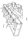
- Figure 6 is an enlarged perspective view of component manufacturing apparatus 102.
- Drive assembly 116 is coupled to positioning assembly 108.
- Multiple turbine blades 112 are coupled to multiple fixtures 110 to illustrate the ability to coat a plurality of blades 112 in a single coating cycle.
- a single fixture spool may be coupled to base assembly 108 in place of drive assembly 116 to facilitate coating a single blade 112.
- Platen 114 is coupled to the spool
- fixture 110 is coupled to platen 114
- blade 112 is coupled to fixture 110.
- Tilt and rotation is substantially similar to that described above with the exception being that the length of time of the coating cycle and the movement of spray nozzle 105 may be reduced to account for the smaller number of blades 112.
- the component manufacturing assembly described herein facilitates manufacturing of a component. More specifically, the component manufacturing assembly will position turbine components to facilitate application of coatings. As a result, the time and expense of manufacturing turbine components can be reduced.
Landscapes
- Engineering & Computer Science (AREA)
- Chemical & Material Sciences (AREA)
- Mechanical Engineering (AREA)
- Materials Engineering (AREA)
- Plasma & Fusion (AREA)
- Chemical Kinetics & Catalysis (AREA)
- Physics & Mathematics (AREA)
- Metallurgy (AREA)
- Organic Chemistry (AREA)
- Spray Control Apparatus (AREA)
- Nozzles (AREA)
- Automatic Assembly (AREA)
- Details Or Accessories Of Spraying Plant Or Apparatus (AREA)
Abstract
Description
- The present invention relates generally to manufacturing components, and more specifically to methods and apparatus for aligning, supporting, and/or securing components for manufacture.
- Accurate manufacturing of gas turbine engine components may be a significant factor in determining both manufacturing timing and cost. Specifically, when the component is a gas turbine engine blade, accurate manufacturing of the blade may be a significant factor affecting an overall cost of fabrication of the gas turbine engine, as well as subsequent modifications, repairs, and inspections of the blade. For example, at least some known gas turbine engine blades receive a protective coating to facilitate protection of the turbine blades when the blades are subjected to high velocity fluid flows in a high temperature environment. Accurately coating the turbine blades facilitates enhancing a useful life of the blades.
- To align a turbine blade for spray coating, known systems enable a single blade to be coupled to a positioning system to enable a spray coating to be applied to the blade. At least some known positioning systems require the blades be repositioned several times through a variety of orientations to enable the coating to be applied at the desired thickness across each portion of the blade to be coated. The process is then repeated for each blade requiring a coating. As such, applying a coating to a component using known systems may be a time consuming process that increases engine manufacturing cycle times and fabrication costs.
- In one aspect, a method for manufacturing components is provided. The method includes coupling a drive assembly to a positioning assembly, coupling a plurality of components to be manufactured to a plurality of fixtures, securing the plurality of fixtures to the drive assembly wherein each fixture is configured to receive a component to be manufactured, and repositioning the plurality of components simultaneously using the positioning assembly to facilitate manufacturing of the plurality of components, wherein the components are configured to be oscillated in a first plane of rotation via the drive assembly and rotated through a second plane of rotation via the plurality of fixtures.
- In another aspect, a fixture assembly for use in manufacturing a plurality of components is provided. The fixture assembly includes at least two fixtures configured to support the plurality of components being manufactured, a drive assembly, the at least two fixtures coupled to the drive assembly and rotatable along a first axis of rotation, the drive assembly comprises a plurality of spindles extending outward therefrom and a plurality of platens coupled to the spindles, the plurality of spindles and the plurality of platens configured to oscillate in a second plane of rotation that is orthogonal to the first axis of rotation.
- In a further aspect, a coating system is provided. The coating system includes a drive assembly, a fixture assembly comprising at least two fixtures coupled to the drive assembly, and a positioning assembly coupled to the fixture assembly, the drive assembly comprises a plurality of spindles extending outward therefrom and a plurality of platens coupled to the spindles, the plurality of spindles and the plurality of platens configured to oscillate in a second plane of rotation that is orthogonal to the first axis of rotation.
- Embodiments of the present invention will now be described, by way of example only, with reference to the accompanying drawings, in which:
- Figure 1 is a perspective view of an exemplary component spray coating system including a component manufacturing assembly;
- Figure 2 is a schematic of an end view of an exemplary component manufacturing apparatus used with the spray coating system shown in Figure 1;
- Figure 3 is a perspective view of a portion of a partially assembled drive assembly used with the spray coating system shown in Figure 1;
- Figure 4 is an end perspective view of the drive assembly shown in Figure 3 and in an intermittent stage of assembly;
- Figure 5 is a side view of the drive assembly shown in Figure 3 and in a final stage of assembly; and
- Figure 6 is an enlarged perspective view of the component manufacturing apparatus assembly shown in Figure 1.
- Figure 1 is a perspective view of an exemplary embodiment of a component
spray coating system 100 in a first position. In the exemplary embodiment,system 100 is used to sprayturbine blades 112.System 100 includes acoating applicator 104 having aspray nozzle 105, acomponent manufacturing apparatus 102 that includes afixture assembly 106, and a positioning and coating control system (not shown on Figure 1). In Figure 1fixture assembly 106 is rotated towardscoating applicator 104 and is coupled to apositioning assembly 108. -
Fixture assembly 106 includes a plurality offixtures 110 used to secure the components. More specifically, in the exemplary embodiment,assembly 106 includes fourfixtures 110 which enable fourturbine blades 112 to be coated simultaneously as described in more detail below. In an alternative embodiment,assembly 106 includes any number of a plurality offixtures 110.Turbine blades 112 are shown for illustrative purposes only andfixture assembly 106 is not limited to only being used in the manufacture ofblades 112.Fixture 110 is securely coupled to a respective one of a plurality ofplatens 114. The exemplary embodiment includes fourplatens 114 that each cooperate with arespective fixture 110.Platens 114 are each coupled to adrive assembly 116. -
Drive assembly 116 includes anenclosure 117 that contains a plurality of drive gears (not shown in Figure 1) coupled to a plurality of spindles (not shown in Figure 1) andplatens 114. Spindles (not shown in Figure 1) extend outwardly fromassembly 116, and the plurality of drive gears are sized, positioned, and aligned to enable each spindle andplaten 114 rotate at substantially the same rate.Drive assembly 116 includes amounting frame 119 and a plurality oflifting slots 121 that are formed integrally withmounting frame 119. The arrows labeled J8 on Figure 1 illustrate a plane of rotation and a direction of rotation ofplatens 114.Drive assembly 116 also houses a plurality of upper bearings (not shown in Figure 1), a plurality of platen-to-spindle biased couplings (not shown in Figure 1), a plurality of collars (not shown in Figure 1), a main drive gear (not shown in Figure 1), a plurality of platen drive gears (not shown in Figure 1), a plurality of inter-platen drive gears (not shown in Figure 1), a main drive gear drive shaft (not shown in Figure 1), and a plurality of lower bearings (not shown in Figure 1). - In the exemplary embodiment,
positioning assembly 108 is a turntable that has been modified and that includes a plurality of floor supports 122, a tilt driveelectric motor 124, a tilt drive shaft and support bearing (not shown in Figure 1), aplaten drive motor 126, a platen drivetranslational gear 128, a plurality ofelectric power cables 130, and a raisedfloor stand 132.Assembly 108 also includes a platen drive shaft-to-main drive gear drive shaft coupling (not shown in Figure 1) through whichassembly 108 powers driveassembly 116. In Figure 1, the arrows labeled J7 illustrate a tilt plane of rotation and a direction of rotation ofassembly 106. - Figure 2 is a schematic of an end view of a
component manufacturing apparatus 102 used withcoating system 100. In addition tospindles 120,assembly 102 also includes a plurality ofupper bearings 150, a plurality ofcollars 152, amain drive gear 154, a plurality ofplaten drive gears 156, a plurality ofinter-platen drive gears 158, a plurality of inter-platendrive gear shafts 159, a main drivegear drive shaft 160, a plurality oflower bearings 162, aplaten drive shaft 164, a drive assembly-to-positioning assembly coupling 166, atilt drive shaft 168, a tilt drive shaft bearing 170 and a tilt axis ofrotation 172. Bearing 170 supportstilt drive shaft 168. A platen drive shaft-to-main drive gear drive shaft coupling (not shown in Figure 2) rotatably coupled to driveshaft 164 to driveshaft 160. - In the exemplary embodiment four fixtures 110 (shown in Figure 1) are securely coupled each
respective platen 114 to enable up to four turbine blades 112 (shown in Figure 1) to be coupled toapparatus 102. Platen driveelectric motor 126 is coupled toplaten drive shaft 164 viatranslational gear 128.Gear 128 receives input frommotor 126 and causesdrive shaft 164 to rotate in a plane of rotation that is orthogonal to tilt axis ofrotation 172. More specifically, in the exemplary embodiment, the rotation may be in a clockwise or counterclockwise direction, or themotor 126 may cause oscillation between the two rotational directions. -
Drive shaft 164 is rotatably coupled to main drivegear drive shaft 160 via platen drive shaft-to-main drive gear drive shaft coupling (not shown in Figure 2) and rotation is induced to driveshaft 160 fromdrive shaft 164.Drive shaft 160 subsequently rotatesmain drive gear 154 which causes rotation of two adjacentplaten drive gears 156.Gears 156 transmit rotation tointer-plated drive gears 158 located adjacent togears 156.Gears 158 transmit rotation to a second pair ofplaten drive gears 156 adjacent togears 158.Upper bearings 150,collars 152,lower bearings 162, andinter-platen drive shafts 159 provide axial and radial support forgears - Rotation transmitted to
platens 114 subsequently oscillatesfixtures 110 andblades 112 such that an orientation ofblades 112 is selectively changed in unison with respect tospray nozzle 105. More specifically, in the exemplary embodiment, the rotation transmitted toplatens 114 is substantially uniform such that the orientation ofblades 112 with respect tospray nozzle 105 is changed in a substantially constant manner that facilitates a consistent deposition of a coating being applied to each of allblades 112. - Moreover, during operation,
positioning assembly 108 also provides tilt rotation alongtilt axis 172. More specifically, tilt driveelectric motor 124 induces rotation totilt drive shaft 168 becauseshaft 168 is coupled topositioning assembly 108, tilt rotation is transmitted topositioning assembly 108. In the exemplary embodiment,positioning assembly 108 is coupled tofixture assembly 106 and as tilt rotation is transmitted to positioningassembly 108,assembly 106 tilts simultaneously withassembly 108 to selectively change the orientation ofblades 112 with respect tospray nozzle 105. Selective tilt rotation ofblades 112 facilitates a consistent deposition of a coating being applied toblade 112. -
Spray nozzle 105 is selectively moveable in a direction that is substantially parallel to, and radially toward and away from,component manufacturing apparatus 102. The movement ofspray nozzle 105, and the oscillation and tilting ofblades 112 are selectively controlled via a positioning and coating control sub-system (not shown in Figure 2) that includes a plurality of inputs, a plurality of outputs, a plurality of algorithms, a plurality of operator interfaces, and at least one processor to facilitate a desired deposition of coating being concurrently applied toblades 112. - Figure 3 is a perspective view of a portion of a partially assembled
drive assembly 116 used with coating system 100 (shown in Figure 1). Figure 4 is an end perspective view ofdrive assembly 116 in an intermittent stage of assembly. During assembly ofdrive assembly 116,main drive gear 154 is coupled to main drivegear drive shaft 160 and is supported by lower bearing 162 (not shown in Figure 3).Collar 152 is coupled to main drivegear drive shaft 160 and supported bymain drive gear 154. Two platen drive gears 156 are coupled aroundspindles 120 and supported by lower bearing 162 (not shown in Figure 3) on opposite sides ofmain drive gear 154.Collars 152 are inserted overspindles 120 and are positioned in contact with platen drive gears 156. Two inter-platen drive gears 158 are coupled around inter-platendrive gear shafts 159 and supported by lower bearings 162 (not shown in Figure 3) such thatcollars 152 are in contact with inter-platen drive gears 158 on opposite sides of platen drive gears 156. Two platen drive gears 156 are coupled tospindles 120 and supported by lower bearing 162 (not shown in Figure 3) on opposite sides of inter-platen drive gears 158. A biased spindle-to-platen coupling 210 is coupled to eachspindle 120. Platens 114 (not shown in Figure 3) are inserted overspindles 120 and spring-loaded,biased couplings 210 securely engageplatens 114 through direct contact ofcoupling 210 to platen 114 inner wall.Top section 220 is then coupled toassembly 116. - Figure 5 is a side view of
drive assembly 116 in a final stage of assembly with a platen brace 230 installed. Brace 230 facilitates maintainingplatens 114 in a relatively stationary position during transport to and installation ofassembly 116 topositioning assembly 108. During installation ofdrive assembly 116, straps (not shown in Figure 5) are inserted through liftingslots 121 on both sides ofassembly 116. A chain (not shown in Figure 5) may be inserted through at least one strap loop (not shown in Figure 5) and may be coupled to a hoisting mechanism (not shown in Figure 5), to enableassembly 116 to be transported to, and coupled to, positioning assembly 108 (not shown in Figure 5). - Figure 6 is an enlarged perspective view of
component manufacturing apparatus 102.Drive assembly 116 is coupled topositioning assembly 108.Multiple turbine blades 112 are coupled tomultiple fixtures 110 to illustrate the ability to coat a plurality ofblades 112 in a single coating cycle. - In an alternate embodiment of
fixture assembly 106, a single fixture spool may be coupled tobase assembly 108 in place ofdrive assembly 116 to facilitate coating asingle blade 112.Platen 114 is coupled to the spool,fixture 110 is coupled toplaten 114 andblade 112 is coupled tofixture 110. Tilt and rotation is substantially similar to that described above with the exception being that the length of time of the coating cycle and the movement ofspray nozzle 105 may be reduced to account for the smaller number ofblades 112. - The component manufacturing assembly described herein facilitates manufacturing of a component. More specifically, the component manufacturing assembly will position turbine components to facilitate application of coatings. As a result, the time and expense of manufacturing turbine components can be reduced.
- Although the methods and systems described and/or illustrated herein are described and/or illustrated with respect to manufacturing components, and more specifically, turbine blades, practice of the methods and systems described and/or illustrated herein is not limited to turbine blades nor to turbines generally. Rather, the methods and systems described and/or illustrated herein are applicable to manufacturing any component on any machine.
- Exemplary embodiments of manufacturing components are described above in detail. The methods, apparatus and systems are not limited to the specific embodiments described herein nor to the specific components manufactured, but rather, may be utilized independently and separately from other methods, apparatus and systems described herein or to manufacture components not described herein. For example, other components can also be manufactured using the methods described herein.
- While the invention has been described in terms of various specific embodiments, those skilled in the art will recognize that the invention can be practiced with modification within the spirit and scope of the claims.
PARTS LIST 100 Component spray coating system 102 Component manufacturing apparatus 104 Coating applicator 105 Spray nozzle 106 Fixture assembly 108 Positioning assembly 110 Fixture 112 Turbine blades 114 Platens 116 Drive assembly 117 Enclosure 119 Mounting frame 120 Spindles 121 Lifting slots 122 Floor supports 124 Tilt drive electric motor 126 Platen drive electric motor 128 Platen drive translational gear 130 Electric power cables 132 Raised floor stand 150 Upper bearings 152 Collars 154 Main drive gear 156 Platen drive gears 158 Inter-platen drive gears 159 Platen drive gear shafts 160 Drive gear drive shaft 162 Lower bearings 164 Platen drive shaft 166 Drive assembly-to- positioning assembly coupling 168 Tilt drive shaft 170 Tilt drive shaft bearing 172 Tilt axis of rotation 210 Biased spindle-to- platen coupling 220 Top section 230 Platen brace
Claims (10)
- A fixture assembly (106) for use in manufacturing a plurality of components, said fixture assembly comprising:at least two fixtures (110) configured to support the plurality of components being manufactured; anda drive assembly (116), said at least two fixtures coupled to said drive assembly and rotatable along a first axis of rotation, said drive assembly comprises a plurality of spindles (120) extending outward therefrom and a plurality of platens (114) coupled to said spindles, said plurality of spindles and said plurality of platens configured to oscillate in a second plane of rotation that is orthogonal to said first axis of rotation.
- A fixture assembly (106) in accordance with Claim 1 wherein said at least one fixture (110) comprises a fastening mechanism configured to secure each of the plurality of components to a respective one of said plurality of fixtures such that the plurality of components are secured in position with respect to said drive assembly (116).
- A fixture assembly (106) in accordance with Claim 1 wherein said drive assembly (116) further comprises a plurality of drive gears configured to simultaneously position each of said at least two fixtures (110).
- A fixture assembly (106) in accordance with Claim 1 wherein said plurality of platens (114) are each securely coupled to said plurality of spindles (120) via a plurality of biased couplings (210), said plurality of platens are configured to support the plurality of components thereon.
- A fixture assembly (106) in accordance with Claim 1 wherein said plurality of platens (114) are spaced apart at pre-determined distances such that a component coupled to a first of said plurality of platens is rotatable relative to said drive assembly (116) without contacting a fixture (110) coupled to an immediately adjacent of said plurality of platens.
- A fixture assembly (106) in accordance with Claim 1 wherein said drive assembly (116) comprises a centerline axis of symmetry, said plurality of spindles (120) are aligned substantially concentrically with respect to said drive assembly axis of symmetry.
- A fixture assembly (106) in accordance with Claim 1 wherein said drive assembly (116) further comprises a mounting frame (119) comprising an enclosure housing (117), a plurality of bearings (150, 162), and a plurality of drive gears (154, 156, 158), each of said plurality of bearings and said plurality of drive gears coupled to said plurality of fixtures.
- A component manufacturing system comprising:a drive assembly (116);a fixture assembly (106) comprising at least two fixtures (110) coupled to said drive assembly; anda positioning assembly (108) coupled to said fixture assembly, said drive assembly comprises a plurality of spindles (120) extending outward therefrom and a plurality of platens (114) coupled to said spindles, said plurality of spindles and said plurality of platens configured to oscillate in a second plane of rotation that is orthogonal to said first axis of rotation.
- A component manufacturing system in accordance with Claim 8 wherein said positioning assembly (108) is configured to align said fixture assembly (106) relative to a spray nozzle.
- A component manufacturing system in accordance with Claim 8 wherein said positioning assembly (108) comprises at least one tilt drive mechanism coupled to said fixture assembly (106) for positioning said fixture assembly, said positioning assembly coupled to a control mechanism.
Applications Claiming Priority (1)
| Application Number | Priority Date | Filing Date | Title |
|---|---|---|---|
| US11/231,499 US7597762B2 (en) | 2005-09-21 | 2005-09-21 | Methods and apparatus for manufacturing components |
Publications (2)
| Publication Number | Publication Date |
|---|---|
| EP1767309A1 true EP1767309A1 (en) | 2007-03-28 |
| EP1767309B1 EP1767309B1 (en) | 2009-03-04 |
Family
ID=37547573
Family Applications (1)
| Application Number | Title | Priority Date | Filing Date |
|---|---|---|---|
| EP06254842A Not-in-force EP1767309B1 (en) | 2005-09-21 | 2006-09-18 | Methods and apparatus for manufacturing components |
Country Status (6)
| Country | Link |
|---|---|
| US (1) | US7597762B2 (en) |
| EP (1) | EP1767309B1 (en) |
| JP (1) | JP2007083232A (en) |
| KR (1) | KR20070033278A (en) |
| CN (1) | CN1935390B (en) |
| DE (1) | DE602006005437D1 (en) |
Cited By (1)
| Publication number | Priority date | Publication date | Assignee | Title |
|---|---|---|---|---|
| FR3055822A1 (en) * | 2016-09-13 | 2018-03-16 | Safran Aircraft Engines | TOOLING FOR MANUFACTURING A TURBOMACHINE BLADE MODEL SCALE |
Families Citing this family (16)
| Publication number | Priority date | Publication date | Assignee | Title |
|---|---|---|---|---|
| US20100175619A1 (en) * | 2009-01-15 | 2010-07-15 | Joseph Garfield Albanese | Part mounting apparatus |
| CN102517535B (en) * | 2011-11-25 | 2014-07-09 | 株洲南方燃气轮机成套制造安装有限公司 | Workpiece spraying device |
| US9409292B2 (en) | 2013-09-13 | 2016-08-09 | Sarcos Lc | Serpentine robotic crawler for performing dexterous operations |
| US9566711B2 (en) | 2014-03-04 | 2017-02-14 | Sarcos Lc | Coordinated robotic control |
| GB201514724D0 (en) * | 2015-08-19 | 2015-09-30 | Rolls Royce Plc | Methods, apparatus, computer programs, and non-transitory computer readble storage mediums for repairing aerofoils of gas turbine engines |
| US10071303B2 (en) | 2015-08-26 | 2018-09-11 | Malibu Innovations, LLC | Mobilized cooler device with fork hanger assembly |
| US10807659B2 (en) | 2016-05-27 | 2020-10-20 | Joseph L. Pikulski | Motorized platforms |
| KR102601494B1 (en) * | 2016-01-22 | 2023-11-10 | 쇼다 테크트론 가부시키가이샤 | single sided applicator |
| CN106179893B (en) * | 2016-08-25 | 2019-08-13 | 迈得医疗工业设备股份有限公司 | Fixture rotary positioning apparatus and the curing apparatus for including the device |
| US10570753B2 (en) | 2017-01-23 | 2020-02-25 | United Technologies Corporation | Apparatus and method for masking under platform areas of airfoil components |
| CN116748084B (en) * | 2017-08-29 | 2025-12-30 | 东莞市泰诚光电有限公司 | Lens module assembly machine |
| KR102598760B1 (en) * | 2018-11-28 | 2023-11-06 | 나이키 이노베이트 씨.브이. | Manufacturing systems for coating articles |
| EP3887061B1 (en) * | 2018-11-28 | 2024-05-01 | Nike Innovate C.V. | Manufacturing system for coating an article |
| KR102147768B1 (en) * | 2019-10-25 | 2020-08-25 | 주식회사 성일터빈 | Fixture to allow several gas turbine blades to be thermal spray coated at once |
| CN111575671B (en) * | 2020-06-12 | 2022-03-29 | 中国人民解放军空军工程大学 | Clamp for preparing coating on selected area of blade surface and preparation method of coating |
| KR102689263B1 (en) * | 2021-12-31 | 2024-07-30 | 한전케이피에스 주식회사 | Robot system for gas turbine rotor blade flame spray coating and method therefor |
Citations (3)
| Publication number | Priority date | Publication date | Assignee | Title |
|---|---|---|---|---|
| US3124986A (en) * | 1954-01-16 | 1964-03-17 | Automatic controls for machine tools | |
| FR2074300A5 (en) * | 1969-12-27 | 1971-10-01 | Nippon Seiko Kk | |
| US3890057A (en) * | 1974-06-13 | 1975-06-17 | Overmyer Mould Company Of Penn | Multi-station drill apparatus |
Family Cites Families (22)
| Publication number | Priority date | Publication date | Assignee | Title |
|---|---|---|---|---|
| CH591923A5 (en) * | 1974-10-07 | 1977-10-14 | Citizen Watch Co Ltd | |
| US4271005A (en) * | 1979-12-03 | 1981-06-02 | United Technologies Corporation | Workpiece support apparatus for use with cathode sputtering devices |
| JPH0340380Y2 (en) * | 1986-05-23 | 1991-08-26 | ||
| US5037676A (en) * | 1989-12-27 | 1991-08-06 | Xerox Corporation | Method and apparatus for cleaning, coating and curing receptor substrates in an enclosed planetary array |
| US5216808A (en) | 1990-11-13 | 1993-06-08 | General Electric Company | Method for making or repairing a gas turbine engine component |
| JP3150746B2 (en) * | 1992-03-06 | 2001-03-26 | 大阪酸素工業株式会社 | Apparatus for forming a resin film on the surface of a three-dimensional structure |
| US5507306A (en) | 1993-12-23 | 1996-04-16 | Howmet Corporation | Cleaning apparatus and method for cleaning internal airfoil cooling passages |
| DE4425991C1 (en) * | 1994-07-22 | 1995-12-07 | Mtu Muenchen Gmbh | Partial coating of parts with precious metals |
| JPH0889912A (en) * | 1994-09-21 | 1996-04-09 | Sumitomo Rubber Ind Ltd | Cleaning equipment |
| US5565035A (en) | 1996-03-14 | 1996-10-15 | United Technologies Corporation | Fixture for masking a portion of an airfoil during application of a coating |
| US6083322A (en) * | 1997-03-06 | 2000-07-04 | United Technologies Corporation | Modular coating fixture |
| US5792267A (en) * | 1997-05-16 | 1998-08-11 | United Technologies Corporation | Coating fixture for a turbine engine blade |
| US5849359A (en) * | 1997-07-17 | 1998-12-15 | United Technologies Corporation | Variable tilting tumbler vacuum coating apparatus |
| US5972424A (en) | 1998-05-21 | 1999-10-26 | United Technologies Corporation | Repair of gas turbine engine component coated with a thermal barrier coating |
| CN2333468Y (en) * | 1998-07-16 | 1999-08-18 | 万向钱潮股份有限公司 | Numerically controlled drilling machine |
| US6042880A (en) | 1998-12-22 | 2000-03-28 | General Electric Company | Renewing a thermal barrier coating system |
| EP1163428B1 (en) | 1999-03-24 | 2004-08-25 | Siemens Aktiengesellschaft | Guide blade and guide blade rim for a fluid-flow machine and component for delimiting a flow channel |
| JP2002035658A (en) * | 2000-07-24 | 2002-02-05 | Yamaha Motor Co Ltd | Painting system |
| US6606541B2 (en) | 2001-04-30 | 2003-08-12 | United Technologies Corporation | Automated system for repairing components |
| US6502304B2 (en) | 2001-05-15 | 2003-01-07 | General Electric Company | Turbine airfoil process sequencing for optimized tip performance |
| US6532656B1 (en) | 2001-10-10 | 2003-03-18 | General Electric Company | Gas turbine engine compressor blade restoration method |
| US7178254B2 (en) | 2005-06-30 | 2007-02-20 | United Technologies Corporation | Marking fixtures and methods |
-
2005
- 2005-09-21 US US11/231,499 patent/US7597762B2/en not_active Expired - Fee Related
-
2006
- 2006-09-18 DE DE602006005437T patent/DE602006005437D1/en active Active
- 2006-09-18 EP EP06254842A patent/EP1767309B1/en not_active Not-in-force
- 2006-09-19 CN CN2006101395901A patent/CN1935390B/en not_active Expired - Fee Related
- 2006-09-20 KR KR1020060091379A patent/KR20070033278A/en not_active Ceased
- 2006-09-21 JP JP2006255146A patent/JP2007083232A/en not_active Ceased
Patent Citations (3)
| Publication number | Priority date | Publication date | Assignee | Title |
|---|---|---|---|---|
| US3124986A (en) * | 1954-01-16 | 1964-03-17 | Automatic controls for machine tools | |
| FR2074300A5 (en) * | 1969-12-27 | 1971-10-01 | Nippon Seiko Kk | |
| US3890057A (en) * | 1974-06-13 | 1975-06-17 | Overmyer Mould Company Of Penn | Multi-station drill apparatus |
Cited By (1)
| Publication number | Priority date | Publication date | Assignee | Title |
|---|---|---|---|---|
| FR3055822A1 (en) * | 2016-09-13 | 2018-03-16 | Safran Aircraft Engines | TOOLING FOR MANUFACTURING A TURBOMACHINE BLADE MODEL SCALE |
Also Published As
| Publication number | Publication date |
|---|---|
| EP1767309B1 (en) | 2009-03-04 |
| CN1935390B (en) | 2013-03-20 |
| DE602006005437D1 (en) | 2009-04-16 |
| CN1935390A (en) | 2007-03-28 |
| US7597762B2 (en) | 2009-10-06 |
| US20070062018A1 (en) | 2007-03-22 |
| KR20070033278A (en) | 2007-03-26 |
| JP2007083232A (en) | 2007-04-05 |
Similar Documents
| Publication | Publication Date | Title |
|---|---|---|
| EP1767309B1 (en) | Methods and apparatus for manufacturing components | |
| JP5186368B2 (en) | Unequal length link SCARA arm | |
| US9126330B2 (en) | Carrier device and robot system | |
| JP3290620B2 (en) | Method and apparatus for coating a workpiece | |
| KR20020001891A (en) | Reinforcement ring for the tower of a wind energy facility | |
| US6224319B1 (en) | Material handling device with overcenter arms and method for use thereof | |
| US20020148512A1 (en) | Throttle valve assembly | |
| KR20110062151A (en) | Jig for case coating of mobile terminal | |
| KR101322587B1 (en) | Rotation transmission mechanism, conveyance device and drive device | |
| CN103975276B (en) | Rotate developing method and device | |
| CN100481370C (en) | Device for transfer of flat display panel | |
| CN107795380B (en) | Method and apparatus for mounting and handling a combustor mounted in a turbine casing | |
| CN113580053B (en) | Engine turbine assembly horizontal assembling device and using method thereof | |
| JP2604690B2 (en) | Automatic flange assembly welding apparatus and automatic flange assembly welding method | |
| KR101719701B1 (en) | A forming device of a pipe | |
| CN109550626A (en) | A kind of spray process platform and spraying process control system | |
| JP2000159338A (en) | Conveying apparatus | |
| KR20220001603U (en) | Shaft transfer apparatus | |
| JP3755744B2 (en) | Substrate transfer robot | |
| KR102335275B1 (en) | Transfer device | |
| JP5581923B2 (en) | Support for supporting semiconductor wafer and method for supporting semiconductor wafer using support | |
| JP4962880B2 (en) | Articulated robot and manufacturing method of production equipment | |
| KR100586188B1 (en) | Board Transfer Device | |
| CN106319479B (en) | Belt positioning device and aumospheric pressure cvd equipment | |
| CN222475427U (en) | A new type of turntable latch positioning mechanism and rotary feeding equipment |
Legal Events
| Date | Code | Title | Description |
|---|---|---|---|
| PUAI | Public reference made under article 153(3) epc to a published international application that has entered the european phase |
Free format text: ORIGINAL CODE: 0009012 |
|
| AK | Designated contracting states |
Kind code of ref document: A1 Designated state(s): AT BE BG CH CY CZ DE DK EE ES FI FR GB GR HU IE IS IT LI LT LU LV MC NL PL PT RO SE SI SK TR |
|
| AX | Request for extension of the european patent |
Extension state: AL BA HR MK YU |
|
| RIN1 | Information on inventor provided before grant (corrected) |
Inventor name: DICKINSON, JON E. Inventor name: SHALVOY, ROBERT SCOTT Inventor name: ALBANESE, JOSEPH GARFIELD |
|
| 17P | Request for examination filed |
Effective date: 20070928 |
|
| 17Q | First examination report despatched |
Effective date: 20071105 |
|
| AKX | Designation fees paid |
Designated state(s): DE FR GB IT |
|
| GRAP | Despatch of communication of intention to grant a patent |
Free format text: ORIGINAL CODE: EPIDOSNIGR1 |
|
| GRAS | Grant fee paid |
Free format text: ORIGINAL CODE: EPIDOSNIGR3 |
|
| GRAA | (expected) grant |
Free format text: ORIGINAL CODE: 0009210 |
|
| AK | Designated contracting states |
Kind code of ref document: B1 Designated state(s): DE FR GB IT |
|
| REG | Reference to a national code |
Ref country code: GB Ref legal event code: FG4D |
|
| REF | Corresponds to: |
Ref document number: 602006005437 Country of ref document: DE Date of ref document: 20090416 Kind code of ref document: P |
|
| PLBE | No opposition filed within time limit |
Free format text: ORIGINAL CODE: 0009261 |
|
| STAA | Information on the status of an ep patent application or granted ep patent |
Free format text: STATUS: NO OPPOSITION FILED WITHIN TIME LIMIT |
|
| 26N | No opposition filed |
Effective date: 20091207 |
|
| PGFP | Annual fee paid to national office [announced via postgrant information from national office to epo] |
Ref country code: GB Payment date: 20120925 Year of fee payment: 7 |
|
| PGFP | Annual fee paid to national office [announced via postgrant information from national office to epo] |
Ref country code: DE Payment date: 20130927 Year of fee payment: 8 |
|
| PGFP | Annual fee paid to national office [announced via postgrant information from national office to epo] |
Ref country code: FR Payment date: 20130919 Year of fee payment: 8 |
|
| PGFP | Annual fee paid to national office [announced via postgrant information from national office to epo] |
Ref country code: IT Payment date: 20130923 Year of fee payment: 8 |
|
| GBPC | Gb: european patent ceased through non-payment of renewal fee |
Effective date: 20130918 |
|
| PG25 | Lapsed in a contracting state [announced via postgrant information from national office to epo] |
Ref country code: GB Free format text: LAPSE BECAUSE OF NON-PAYMENT OF DUE FEES Effective date: 20130918 |
|
| REG | Reference to a national code |
Ref country code: DE Ref legal event code: R119 Ref document number: 602006005437 Country of ref document: DE |
|
| REG | Reference to a national code |
Ref country code: FR Ref legal event code: ST Effective date: 20150529 |
|
| PG25 | Lapsed in a contracting state [announced via postgrant information from national office to epo] |
Ref country code: DE Free format text: LAPSE BECAUSE OF NON-PAYMENT OF DUE FEES Effective date: 20150401 |
|
| PG25 | Lapsed in a contracting state [announced via postgrant information from national office to epo] |
Ref country code: IT Free format text: LAPSE BECAUSE OF NON-PAYMENT OF DUE FEES Effective date: 20140918 Ref country code: FR Free format text: LAPSE BECAUSE OF NON-PAYMENT OF DUE FEES Effective date: 20140930 |