EP1765208B1 - Apparatus for retaining screws in a plate - Google Patents
Apparatus for retaining screws in a plate Download PDFInfo
- Publication number
- EP1765208B1 EP1765208B1 EP05762461A EP05762461A EP1765208B1 EP 1765208 B1 EP1765208 B1 EP 1765208B1 EP 05762461 A EP05762461 A EP 05762461A EP 05762461 A EP05762461 A EP 05762461A EP 1765208 B1 EP1765208 B1 EP 1765208B1
- Authority
- EP
- European Patent Office
- Prior art keywords
- plate
- cap
- aperture
- ring
- cavity
- Prior art date
- Legal status (The legal status is an assumption and is not a legal conclusion. Google has not performed a legal analysis and makes no representation as to the accuracy of the status listed.)
- Expired - Lifetime
Links
Images


Classifications
-
- A—HUMAN NECESSITIES
- A61—MEDICAL OR VETERINARY SCIENCE; HYGIENE
- A61B—DIAGNOSIS; SURGERY; IDENTIFICATION
- A61B17/00—Surgical instruments, devices or methods
- A61B17/56—Surgical instruments or methods for treatment of bones or joints; Devices specially adapted therefor
- A61B17/58—Surgical instruments or methods for treatment of bones or joints; Devices specially adapted therefor for osteosynthesis, e.g. bone plates, screws or setting implements
- A61B17/68—Internal fixation devices, including fasteners and spinal fixators, even if a part thereof projects from the skin
- A61B17/70—Spinal positioners or stabilisers, e.g. stabilisers comprising fluid filler in an implant
-
- A—HUMAN NECESSITIES
- A61—MEDICAL OR VETERINARY SCIENCE; HYGIENE
- A61B—DIAGNOSIS; SURGERY; IDENTIFICATION
- A61B17/00—Surgical instruments, devices or methods
- A61B17/56—Surgical instruments or methods for treatment of bones or joints; Devices specially adapted therefor
- A61B17/58—Surgical instruments or methods for treatment of bones or joints; Devices specially adapted therefor for osteosynthesis, e.g. bone plates, screws or setting implements
- A61B17/68—Internal fixation devices, including fasteners and spinal fixators, even if a part thereof projects from the skin
- A61B17/80—Cortical plates, i.e. bone plates; Instruments for holding or positioning cortical plates, or for compressing bones attached to cortical plates
- A61B17/8033—Cortical plates, i.e. bone plates; Instruments for holding or positioning cortical plates, or for compressing bones attached to cortical plates having indirect contact with screw heads, or having contact with screw heads maintained with the aid of additional components, e.g. nuts, wedges or head covers
- A61B17/8042—Cortical plates, i.e. bone plates; Instruments for holding or positioning cortical plates, or for compressing bones attached to cortical plates having indirect contact with screw heads, or having contact with screw heads maintained with the aid of additional components, e.g. nuts, wedges or head covers the additional component being a cover over the screw head
-
- A—HUMAN NECESSITIES
- A61—MEDICAL OR VETERINARY SCIENCE; HYGIENE
- A61B—DIAGNOSIS; SURGERY; IDENTIFICATION
- A61B17/00—Surgical instruments, devices or methods
- A61B17/56—Surgical instruments or methods for treatment of bones or joints; Devices specially adapted therefor
- A61B17/58—Surgical instruments or methods for treatment of bones or joints; Devices specially adapted therefor for osteosynthesis, e.g. bone plates, screws or setting implements
- A61B17/68—Internal fixation devices, including fasteners and spinal fixators, even if a part thereof projects from the skin
- A61B17/70—Spinal positioners or stabilisers, e.g. stabilisers comprising fluid filler in an implant
- A61B17/7059—Cortical plates
-
- A—HUMAN NECESSITIES
- A61—MEDICAL OR VETERINARY SCIENCE; HYGIENE
- A61B—DIAGNOSIS; SURGERY; IDENTIFICATION
- A61B17/00—Surgical instruments, devices or methods
- A61B17/56—Surgical instruments or methods for treatment of bones or joints; Devices specially adapted therefor
- A61B17/58—Surgical instruments or methods for treatment of bones or joints; Devices specially adapted therefor for osteosynthesis, e.g. bone plates, screws or setting implements
- A61B17/68—Internal fixation devices, including fasteners and spinal fixators, even if a part thereof projects from the skin
- A61B17/80—Cortical plates, i.e. bone plates; Instruments for holding or positioning cortical plates, or for compressing bones attached to cortical plates
-
- A—HUMAN NECESSITIES
- A61—MEDICAL OR VETERINARY SCIENCE; HYGIENE
- A61B—DIAGNOSIS; SURGERY; IDENTIFICATION
- A61B17/00—Surgical instruments, devices or methods
- A61B17/56—Surgical instruments or methods for treatment of bones or joints; Devices specially adapted therefor
- A61B17/58—Surgical instruments or methods for treatment of bones or joints; Devices specially adapted therefor for osteosynthesis, e.g. bone plates, screws or setting implements
- A61B17/68—Internal fixation devices, including fasteners and spinal fixators, even if a part thereof projects from the skin
- A61B17/82—Internal fixation devices, including fasteners and spinal fixators, even if a part thereof projects from the skin for bone cerclage
-
- A—HUMAN NECESSITIES
- A61—MEDICAL OR VETERINARY SCIENCE; HYGIENE
- A61B—DIAGNOSIS; SURGERY; IDENTIFICATION
- A61B17/00—Surgical instruments, devices or methods
- A61B17/56—Surgical instruments or methods for treatment of bones or joints; Devices specially adapted therefor
- A61B17/58—Surgical instruments or methods for treatment of bones or joints; Devices specially adapted therefor for osteosynthesis, e.g. bone plates, screws or setting implements
- A61B17/68—Internal fixation devices, including fasteners and spinal fixators, even if a part thereof projects from the skin
- A61B17/84—Fasteners therefor or fasteners being internal fixation devices
- A61B17/86—Pins or screws or threaded wires; nuts therefor
-
- A—HUMAN NECESSITIES
- A61—MEDICAL OR VETERINARY SCIENCE; HYGIENE
- A61B—DIAGNOSIS; SURGERY; IDENTIFICATION
- A61B17/00—Surgical instruments, devices or methods
- A61B17/56—Surgical instruments or methods for treatment of bones or joints; Devices specially adapted therefor
- A61B17/58—Surgical instruments or methods for treatment of bones or joints; Devices specially adapted therefor for osteosynthesis, e.g. bone plates, screws or setting implements
- A61B17/68—Internal fixation devices, including fasteners and spinal fixators, even if a part thereof projects from the skin
- A61B17/80—Cortical plates, i.e. bone plates; Instruments for holding or positioning cortical plates, or for compressing bones attached to cortical plates
- A61B17/8033—Cortical plates, i.e. bone plates; Instruments for holding or positioning cortical plates, or for compressing bones attached to cortical plates having indirect contact with screw heads, or having contact with screw heads maintained with the aid of additional components, e.g. nuts, wedges or head covers
- A61B17/8047—Cortical plates, i.e. bone plates; Instruments for holding or positioning cortical plates, or for compressing bones attached to cortical plates having indirect contact with screw heads, or having contact with screw heads maintained with the aid of additional components, e.g. nuts, wedges or head covers wherein the additional element surrounds the screw head in the plate hole
Definitions
- the human spine is a biomechanical structure consisting of thirty-three vertebral members and is responsible for protecting the spinal cord, nerve roots and internal organs of the thorax and abdomen.
- the spine also provides structural support for the body while permitting flexibility of motion.
- it is necessary to secure together two or more of the vertebral members. The procedure may be necessary for example as a result of physical trauma or degenerative diseases.
- One type of surgical procedure includes attachment of a vertebral plate to the vertebral members.
- the vertebral plate is sized to extend across two or more of the vertebral members.
- One or more bone screws extend through apertures in the plate and into the vertebral members to secure the plate.
- One issue with the attachment is the screws may tend to loosen and back-out of the vertebral members. Screw retention devices may be necessary to prevent the screw from backing-out of the vertebral members.
- One type of screw retention device utilizes a snap ring that expands as the screw is inserted into the aperture and then retracts to a smaller diameter once the screw head has passed the level of the snap ring.
- One issue with previous snap ring designs is the inability to use the rings with a variety of different screws. These designs may not be effective for both variable angle and fixed angle screws, or require specialty screws that are designed for only a limited application. Additionally, these previous designs have needed a larger plate thickness to accommodate the snap ring. Another issue is the difficultly for the surgeon to visually see when the lock ring has moved over the top of the screw once the screw has passed the level of the snap ring. Some designs also prevent or limit the ability of the surgeon to tactilely feel the movement of the snap ring as it moves over the top of the screw. Additionally, some designs interfere with the surgeon's feel of the screw purchasing within the bone.
- FR-A-2,794,963 , US-B1-6,602,255 , US 2004/097935 and US 2002/147450 disclose various vertebral or spinal support systems.
- the present invention is directed to a system of retaining screws within a vertebral plate and prevent screw back-out, as defined in claim 1.
- the invention includes a variety of embodiments, with one embodiment having a plate with at least one aperture for receiving a screw. A cavity is positioned within the plate and partially overlaps into the aperture. A ring is positioned within the cavity and held in position by a cap. The ring is resilient and changes shape between an original shape that extends partially over the aperture, and a deflected shape away from the aperture.
- One method includes positioning a resilient member within a cavity in the plate such that it partially extends over the aperture.
- the next step comprises placing a cap over the cavity and attaching the cap to the plate to prevent the resilient member from being removed from the plate.
- the next step includes inserting a screw into the aperture and deflecting the resilient member away from the aperture. The screw is inserted into the vertebral member a predetermined distance, and the resilient member is returned to its original shape over the aperture and over the screw to prevent the screw from backing-out of the aperture.
- the present invention is directed to a retention system for maintaining the position of a screw 70 relative to a vertebral plate 20.
- Figure 1 illustrates one embodiment of a vertebral plate 20 having one or more apertures 21.
- a cavity 22 is positioned adjacent to and overlaps into the aperture 21.
- a ring 50 is positioned within the cavity 22 and held in position by a cap 30.
- the cap 30 attaches to the plate 20 to prevent removal of the ring 50.
- the ring 50 is resilient and changes shape between an original shape that extends over an aperture 21 to prevent screw back-out, and a deflected shape that allows insertion and removal of the screw from the aperture 21 (see Figures 4 and 5 ).
- the plate 20 is sized to extend across one or more vertebral members 100.
- Apertures 21 extend through the plate 20 between a top surface 23 and a bottom surface 24 to receive the bone screws 70.
- the apertures 21 may have a variety of sizes and orientations depending upon the specific application.
- the cavity 22 is positioned adjacent to the aperture 21 and includes a counterbore 29 that extends inward into the plate 20 from the top surface 23.
- the cavity 22 may extend entirely through the plate 20, or may extend only a limited distance into the plate 20 from the top surface 23.
- a depth that the counterbore 29 extends into the top surface 23 may likewise vary depending upon the application.
- the counterbore 29 may form an upper ledge 25 to accommodate the ring 50 as will be explained later.
- the cavity 22 and counterbore 29 are co-axially aligned and each has a substantially circular shape. Various other shapes may also be employed and are contemplated by the present invention.
- the cavity 22 and counterbore 29 are both centered within the medial plane M of the plate 20.
- the plate 20 may have both a medial and lordotic curve to conform to the dimensions of the vertebral members 100.
- the cavity 22 may further include elements to assist with retaining the cap 30.
- a second counterbore 28 may be formed in the bottom surface 24 of the plate 20.
- FIGS 2 and 3 illustrate front and rear perspective views of the cap 30 removed from the plate 20.
- the cap 30 includes a flange 31 and an outwardly extending plug 34.
- the flange 31 includes an upper surface 32 and a lower surface 33. When mounted in the plate 20, the flange 31 seats within the counterbore 29 with the upper surface 32 substantially flush with the top surface 23 of the plate 20.
- the plug 34 has a width generally corresponding to the size of the cavity 22. Ears 36 and slots 39 may be positioned at the edge of the plug 34 opposite the flange 31 and mate with the lower counterbore 28.
- a window 37 may be formed in the plug 34 and provide a contact point for grasping and manipulating the cap 30 and/or plate 20 during a surgical procedure.
- the window 37 may also be used for location and orientation of surgical instruments, such as plate holders, drills, taps, and screw guides.
- the window 37 may extend through the entire cap 30, or may extend only a limited distance inward from the upper surface 32 of the flange 31.
- the window 37 may have a shape to allow medial alignment of the plate 20, such as the oval shape illustrated in the Figures.
- the cap 30 is attached to the plate 20 and maintains the ring 50 within the cavity 22.
- a variety ofmeans may be used for attaching the cap 30 to the plate 20, including for example, interference fit, snap fit, staking, and swaging.
- the cap 30 has external threads along the plug 34 that mate with threads on the inner wall of the cavity 22.
- the cap 30 may also be attached via a removable or non-removable fastener, such as screw, rivet, and the like.
- Figures 4 and 5 illustrate one method of attaching the cap 30 to the plate 20.
- the external features of the plug 34 are sized to contact the sidewall of the cavity 22 and provide an interference fit. Additionally, the ears 36 extend outward into the lower counterbore 28 to further secure the cap 30.
- the ears 36 may be deformed into the lower counterbore 28 during the manufacturing process or alternatively by the surgeon or other medical personnel prior to or during the surgery.
- the ears 36 are grasped by a tool and bent outward away from the cavity thus enlarging the width and preventing the cap 30 from being removed from the plate 20.
- the cap 30 is constructed of a resilient material. When inserted into the cavity 22, the ears 36 resiliently rebound outward into the counterbore 28.
- the position of the ears 36 within the counterbore 28 are illustrated in Figures 4 and 5 .
- Ears 36A illustrate the mounting of the adjacent upper cap 30 (i.e., the cap 30 positioned adjacent to the cross-sectionally cut middle cap 30). In these embodiments, the cap 30 may be retained by only the interference fit, only the deformed ears 36, or by both.
- the ring 50 is positioned within the cavity 22 to prevent back-out of the screw 70.
- the ring 50 is constructed of a resilient spring material that is elastic and deflectable between an original shape when mounted in the cavity 22 that extends outward into the aperture 21, and a deflected state away from the aperture 21 to allow removal and insertion of the screw 70 relative to the aperture 21.
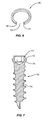
- Figure 6 illustrates one embodiment of the ring 50 having a substantially circular shape with inner and outer diameters and a compression slot 51 formed between first and second ends 52, 53.
- Ring 50 has upper and lower surfaces with the lower surface positioned towards the upper ledge 25 of the counterbore 29. In one embodiment, the lower surface is substantially flat to contact the screw 70 when the ring 50 extends into the aperture 21.
- Figure 6 illustrates one embodiment of ring 50 having a rectangular cross-sectional shape. Another embodiment features a triangular cross-sectional shape.
- the ring 50 may be constructed of a material having elastic properties.
- the ring 50 is made of a Nickel-Titanium alloy that is heat treated to achieve superelastic properties when exposed to a temperature range within the human body.
- the ring 50 may also be constructed of other materials, for example, peek, titanium, or stainless steel.
- the term "ring” is used broadly herein to refer to the member positioned within the cavity. It is understood that the member may have a variety of different shapes and sizes.
- the diameter of the counterbore 29 is less than an outer diameter of the ring 50. This causes the ring 50 to be pre-loaded in the original shape when seated in the counterbore 29. The pre-loaded condition causes the compression slot 51 to be reduced and gives the ring 50 additional expansion force to extend outward over the aperture 21.
- the amount of deflection of the ring 30 may vary depending upon the application. Deflection may occur on one side of the ring 30, or on both sides such as would occur in an embodiment as illustrated in Figures 1 , 4, and 5 as both screws 70 were being inserted.
- Figure 7 illustrates one embodiment of the screw 70 and includes a head 71, shelf 72, spherical radius 73 and shaft 74.
- the shelf 72 extends outward beyond the head 71 and provides a platform for receiving the ring 50.
- the shelf 72 may be substantially flat to provide a good contacting surface for the flat surface of the ring 50.
- the spherical radius 73 has a maximum width at the shelf 72 and reduces to a minimum width at the shaft 74.
- Figures 1 , 4, and 5 illustrate one embodiment of the invention having a cavity 22 positioned between and overlapping into two apertures 21.
- Each of the apertures 21 and cavities 22 has a substantially circular shape with the cavity 22 having a counterbore 29 that overlaps into the apertures.
- the ring 50 has an original shape that extends outward and overlaps into the apertures 21, and a deflected shape in a non-overlapping position away from the aperture 21.
- the ring 50 is in the original shapeprior to screw insertion, and after the screw 70 has been inserted into the aperture 21 and the shelf 72 passes below the level of the ring 50.
- Figure 4 illustrates the ring 50 in the original shape where the shelf 72 is below the level of the ring 50.
- the resilient nature of the ring 50 causes it to return toward the original shape and extend over the shelf 72.
- the ring 50 position prior to screw insertion is illustrated within the middle cavity 22 and apertures 21 of the plate 20 in Figure 1 .
- the insertion and removal of the screw 70 from the aperture 21 causes the ring 50 to deflect and move away from the aperture 21.
- One example is illustrated within the left screw 70 illustrated in Figure 5 .
- the force of the insertion or removal deflects the ring 50 inward from the aperture 21 and further into the counterbore 29.
- the ring 50 overlaps into the apertures 21 a distance once the screw 70 has been inserted to prevent back-out of the screw 70.
- the ring 50 extends outward beyond the edge of the cap flange 31 to allow visual confirmation of the position by a surgeon. This may further be assisted by coloring the ring 50 and screw 70 with contrasting colors to make it easier to visually observe the relative position of these elements.
- the cap flange 31 may have a shape that conforms to the adjacent aperture 21 and prevents the flange 31 from extending over the aperture 21 when the cap 30 is mounted to the plate 20. As illustrated in Figures 2 and 3 , the flange 31 has curved edges 38 that conform to the outer circumference of the aperture 21. Therefore, the flange 31 does not overlap into the aperture 21 while still allowing the ring 50 to overlap into the aperture 21.
- the ring 50 is positioned in the space created between the cap 30 and cavity 21. In one embodiment, both the cap 30 and ring 50 are co-axially aligned within the cavity 22. As illustrated in Figures 2 and 3 , a tab 35 extends outward from the cap 30 to fit within the ring slot 51 and prevent rotation of the ring 50. The tab 35 includes first and second edges that are distanced apart to fit within the slot 51 of the ring 50. This prevents rotation of the ring 50 to a position where the slot 51 is over the aperture 21 and potentially allows the screw 70 to back-out. Tab 35 seats against the upper ledge 25 of the counterbore 29 when the cap 30 is in the cavity 22.
- the spherical radius 73 contacts the ring 50 and deflects it away from the aperture 21.
- the ring 50 is further deflected from its original shape and away from the aperture 21.
- the ring 50 returns towards the original shape to extend over the shelf 72.
- the snapping action of the ring 50 extending over the shelf 72 may be tactilely detected by the surgeon and provide assurance that the ring 50 is seated over the screw 70 to prevent back-out.
- the elastic property of the ring 50 causes a snapping action as the screw passes and does not require the surgeon to proactively engage the ring 50.
- the device includes the ring 50 attached to the cap 30.
- the ring 50 and cap 30 combination may be a single integral piece, or the ring 50 may be a separate piece that is fixedly attached to the cap 30.
- the combination positions the ring 50 over the apertures 21 in the original shape and allows the ring 50 to be deflected upon screw 70 insertion and removal.
- the original shape of the ring 50 is positioned to extend over one or more apertures 21. This original shape may not be the neutral position of the ring 50.
- the shape of the ring 50 may be constrained by the counterbore 29 and have a smaller outer width than if the ring 50 were more freely positioned within a larger space.
- the ring 50 may be in a more deflected state when it returns over the aperture 21 after insertion of the screw 70.
- screw 70 is in the original shape and extends over the aperture 21 a first amount.
- ring 50 deflects away from the aperture 21 to a second shape.
- ring 50 snaps back over the screw 70 to a third shape.
- This third shape may be the same as the original shape, or may be different depending on the position and size of the screw.
- the ring 50 may contact the screw head 71 in the third shape and prevent the ring 50 from fully returning to its original shape.
- the ring 50 may further deflect along a single side, or along more than one side. In the embodiment illustrated in Figures 1 , 4, and 5 , ring 50 extends into two apertures 21 and therefore can be deflected along two separate sides as screws 70 are inserted into the respective apertures 21. In another embodiment where the ring 50 extends only into a single aperture 21, the ring 50 will deflect along a single side.
- vertebral member is used generally to describe the vertebral geometry comprising the vertebral body, pedicles, lamina, and processes.
- the device may be sized and shaped, and have adequate strength requirements to be used within the different regions of the vertebra including the cervical, thoracic, and lumbar regions.
- Figure 1 is included in part to illustrate the relative positioning of the plate 20, ring 50, and cap 30. Neither a cap 30 or ring 50 are attached to the upper cavity 22 to illustrate the position of the cavity 22 and counterbore 29 relative to the adjacent apertures 21. A cap 30 and ring 50 are mounted in the middle cavity to illustrate the ring 50 extending outward into the adjacent apertures 21 when there are no screws 70. The lower cavity 22 illustrates the cap 30 and ring 50 in an exploded view.
- the ring 50 may also have a circular, oval, or elongated cross-sectional shape.
- the ears 36 are positioned within the lower counterbore 28 and are either flush or recessed within the bottom surface 24 of the plate so as not to interfere with positioning on the vertebral member 100.
- the ring 50 extends over the screw head 71 to prevent screw back-out.
- the screw 70 may or may not include a shelf 72 and spherical radius 73.
- the plug 34 and flange 31 form an angle of about 90°.
- a center of the cavity 22 is positioned along a line formed between the centers of the two apertures 21.
- the present embodiments are, therefore, to be considered in all respects as illustrative and not restrictive.
Landscapes
- Health & Medical Sciences (AREA)
- Orthopedic Medicine & Surgery (AREA)
- Life Sciences & Earth Sciences (AREA)
- Surgery (AREA)
- Neurology (AREA)
- Molecular Biology (AREA)
- General Health & Medical Sciences (AREA)
- Biomedical Technology (AREA)
- Heart & Thoracic Surgery (AREA)
- Medical Informatics (AREA)
- Nuclear Medicine, Radiotherapy & Molecular Imaging (AREA)
- Animal Behavior & Ethology (AREA)
- Engineering & Computer Science (AREA)
- Public Health (AREA)
- Veterinary Medicine (AREA)
- Surgical Instruments (AREA)
- Prostheses (AREA)
- Formation And Processing Of Food Products (AREA)
- Supporting Of Heads In Record-Carrier Devices (AREA)
- Feeding Of Articles To Conveyors (AREA)
- Branching, Merging, And Special Transfer Between Conveyors (AREA)
Applications Claiming Priority (2)
| Application Number | Priority Date | Filing Date | Title |
|---|---|---|---|
| US10/870,026 US7727266B2 (en) | 2004-06-17 | 2004-06-17 | Method and apparatus for retaining screws in a plate |
| PCT/US2005/021358 WO2006009795A1 (en) | 2004-06-17 | 2005-06-16 | Method and apparatus for retaining screws in a plate |
Publications (2)
| Publication Number | Publication Date |
|---|---|
| EP1765208A1 EP1765208A1 (en) | 2007-03-28 |
| EP1765208B1 true EP1765208B1 (en) | 2009-03-25 |
Family
ID=35033731
Family Applications (1)
| Application Number | Title | Priority Date | Filing Date |
|---|---|---|---|
| EP05762461A Expired - Lifetime EP1765208B1 (en) | 2004-06-17 | 2005-06-16 | Apparatus for retaining screws in a plate |
Country Status (12)
Families Citing this family (178)
| Publication number | Priority date | Publication date | Assignee | Title |
|---|---|---|---|---|
| US7833250B2 (en) | 2004-11-10 | 2010-11-16 | Jackson Roger P | Polyaxial bone screw with helically wound capture connection |
| US8377100B2 (en) | 2000-12-08 | 2013-02-19 | Roger P. Jackson | Closure for open-headed medical implant |
| US6726689B2 (en) | 2002-09-06 | 2004-04-27 | Roger P. Jackson | Helical interlocking mating guide and advancement structure |
| US10258382B2 (en) | 2007-01-18 | 2019-04-16 | Roger P. Jackson | Rod-cord dynamic connection assemblies with slidable bone anchor attachment members along the cord |
| US10729469B2 (en) | 2006-01-09 | 2020-08-04 | Roger P. Jackson | Flexible spinal stabilization assembly with spacer having off-axis core member |
| US7862587B2 (en) | 2004-02-27 | 2011-01-04 | Jackson Roger P | Dynamic stabilization assemblies, tool set and method |
| US8292926B2 (en) | 2005-09-30 | 2012-10-23 | Jackson Roger P | Dynamic stabilization connecting member with elastic core and outer sleeve |
| US8353932B2 (en) | 2005-09-30 | 2013-01-15 | Jackson Roger P | Polyaxial bone anchor assembly with one-piece closure, pressure insert and plastic elongate member |
| US6755833B1 (en) | 2001-12-14 | 2004-06-29 | Kamaljit S. Paul | Bone support assembly |
| US7070599B2 (en) | 2002-07-24 | 2006-07-04 | Paul Kamaljit S | Bone support assembly |
| AU2005304849B8 (en) | 2002-09-06 | 2009-09-03 | Roger P. Jackson | Helical guide and advancement flange with break-off extensions |
| US8282673B2 (en) | 2002-09-06 | 2012-10-09 | Jackson Roger P | Anti-splay medical implant closure with multi-surface removal aperture |
| US8257402B2 (en) | 2002-09-06 | 2012-09-04 | Jackson Roger P | Closure for rod receiving orthopedic implant having left handed thread removal |
| US8876868B2 (en) | 2002-09-06 | 2014-11-04 | Roger P. Jackson | Helical guide and advancement flange with radially loaded lip |
| US6716214B1 (en) | 2003-06-18 | 2004-04-06 | Roger P. Jackson | Polyaxial bone screw with spline capture connection |
| US8540753B2 (en) | 2003-04-09 | 2013-09-24 | Roger P. Jackson | Polyaxial bone screw with uploaded threaded shank and method of assembly and use |
| US7621918B2 (en) | 2004-11-23 | 2009-11-24 | Jackson Roger P | Spinal fixation tool set and method |
| US7377923B2 (en) | 2003-05-22 | 2008-05-27 | Alphatec Spine, Inc. | Variable angle spinal screw assembly |
| US8814911B2 (en) | 2003-06-18 | 2014-08-26 | Roger P. Jackson | Polyaxial bone screw with cam connection and lock and release insert |
| US8926670B2 (en) | 2003-06-18 | 2015-01-06 | Roger P. Jackson | Polyaxial bone screw assembly |
| US7776067B2 (en) | 2005-05-27 | 2010-08-17 | Jackson Roger P | Polyaxial bone screw with shank articulation pressure insert and method |
| US7967850B2 (en) | 2003-06-18 | 2011-06-28 | Jackson Roger P | Polyaxial bone anchor with helical capture connection, insert and dual locking assembly |
| US7766915B2 (en) | 2004-02-27 | 2010-08-03 | Jackson Roger P | Dynamic fixation assemblies with inner core and outer coil-like member |
| US8366753B2 (en) | 2003-06-18 | 2013-02-05 | Jackson Roger P | Polyaxial bone screw assembly with fixed retaining structure |
| US8257398B2 (en) | 2003-06-18 | 2012-09-04 | Jackson Roger P | Polyaxial bone screw with cam capture |
| US8377102B2 (en) | 2003-06-18 | 2013-02-19 | Roger P. Jackson | Polyaxial bone anchor with spline capture connection and lower pressure insert |
| US8137386B2 (en) | 2003-08-28 | 2012-03-20 | Jackson Roger P | Polyaxial bone screw apparatus |
| US8398682B2 (en) | 2003-06-18 | 2013-03-19 | Roger P. Jackson | Polyaxial bone screw assembly |
| US8092500B2 (en) | 2007-05-01 | 2012-01-10 | Jackson Roger P | Dynamic stabilization connecting member with floating core, compression spacer and over-mold |
| US7306605B2 (en) | 2003-10-02 | 2007-12-11 | Zimmer Spine, Inc. | Anterior cervical plate |
| US7527638B2 (en) | 2003-12-16 | 2009-05-05 | Depuy Spine, Inc. | Methods and devices for minimally invasive spinal fixation element placement |
| US11419642B2 (en) | 2003-12-16 | 2022-08-23 | Medos International Sarl | Percutaneous access devices and bone anchor assemblies |
| US7179261B2 (en) | 2003-12-16 | 2007-02-20 | Depuy Spine, Inc. | Percutaneous access devices and bone anchor assemblies |
| US8900277B2 (en) | 2004-02-26 | 2014-12-02 | Pioneer Surgical Technology, Inc. | Bone plate system |
| US7740649B2 (en) * | 2004-02-26 | 2010-06-22 | Pioneer Surgical Technology, Inc. | Bone plate system and methods |
| US11241261B2 (en) | 2005-09-30 | 2022-02-08 | Roger P Jackson | Apparatus and method for soft spinal stabilization using a tensionable cord and releasable end structure |
| US7160300B2 (en) | 2004-02-27 | 2007-01-09 | Jackson Roger P | Orthopedic implant rod reduction tool set and method |
| US8152810B2 (en) | 2004-11-23 | 2012-04-10 | Jackson Roger P | Spinal fixation tool set and method |
| CA2701522C (en) | 2004-02-27 | 2012-05-15 | Roger P. Jackson | Orthopedic implant rod reduction tool set and method |
| US7572282B2 (en) * | 2004-04-23 | 2009-08-11 | Depuy Spine Sarl | Spinal fixation plates and plate extensions |
| US7651502B2 (en) | 2004-09-24 | 2010-01-26 | Jackson Roger P | Spinal fixation tool set and method for rod reduction and fastener insertion |
| US8926672B2 (en) | 2004-11-10 | 2015-01-06 | Roger P. Jackson | Splay control closure for open bone anchor |
| WO2006057837A1 (en) | 2004-11-23 | 2006-06-01 | Jackson Roger P | Spinal fixation tool attachment structure |
| US9980753B2 (en) | 2009-06-15 | 2018-05-29 | Roger P Jackson | pivotal anchor with snap-in-place insert having rotation blocking extensions |
| US8308782B2 (en) | 2004-11-23 | 2012-11-13 | Jackson Roger P | Bone anchors with longitudinal connecting member engaging inserts and closures for fixation and optional angulation |
| US9168069B2 (en) | 2009-06-15 | 2015-10-27 | Roger P. Jackson | Polyaxial bone anchor with pop-on shank and winged insert with lower skirt for engaging a friction fit retainer |
| US7875065B2 (en) | 2004-11-23 | 2011-01-25 | Jackson Roger P | Polyaxial bone screw with multi-part shank retainer and pressure insert |
| US9216041B2 (en) | 2009-06-15 | 2015-12-22 | Roger P. Jackson | Spinal connecting members with tensioned cords and rigid sleeves for engaging compression inserts |
| US8444681B2 (en) | 2009-06-15 | 2013-05-21 | Roger P. Jackson | Polyaxial bone anchor with pop-on shank, friction fit retainer and winged insert |
| WO2006058221A2 (en) | 2004-11-24 | 2006-06-01 | Abdou Samy M | Devices and methods for inter-vertebral orthopedic device placement |
| US7438715B2 (en) * | 2005-01-06 | 2008-10-21 | Spinal Llc | Spinal implant kit |
| US8353939B2 (en) * | 2005-01-12 | 2013-01-15 | Warsaw Orthopedic, Inc. | Anchor retaining mechanisms for bone plates |
| US7901437B2 (en) | 2007-01-26 | 2011-03-08 | Jackson Roger P | Dynamic stabilization member with molded connection |
| US10076361B2 (en) | 2005-02-22 | 2018-09-18 | Roger P. Jackson | Polyaxial bone screw with spherical capture, compression and alignment and retention structures |
| US7452370B2 (en) | 2005-04-29 | 2008-11-18 | Warsaw Orthopedic, Inc | Apparatus for retaining a bone anchor in a bone plate and method for use thereof |
| US7288094B2 (en) * | 2005-06-10 | 2007-10-30 | Sdgi Holdings, Inc. | System and method for retaining screws relative to a vertebral plate |
| US8105368B2 (en) | 2005-09-30 | 2012-01-31 | Jackson Roger P | Dynamic stabilization connecting member with slitted core and outer sleeve |
| US9119677B2 (en) * | 2005-12-09 | 2015-09-01 | DePuy Synthes Products, Inc. | Spinal plate and drill guide |
| US7704271B2 (en) | 2005-12-19 | 2010-04-27 | Abdou M Samy | Devices and methods for inter-vertebral orthopedic device placement |
| US7875062B2 (en) * | 2006-03-07 | 2011-01-25 | Warsaw Orthopedic, Inc. | Methods and devices for retaining bone plate anchors |
| US8246663B2 (en) * | 2006-04-10 | 2012-08-21 | Scott Lovald | Osteosynthesis plate, method of customizing same, and method for installing same |
| US20070270880A1 (en) * | 2006-04-28 | 2007-11-22 | Lindemann Gary S | Bone screw revision tools and methods of use |
| WO2008005380A2 (en) * | 2006-06-30 | 2008-01-10 | Alphatec Spine, Inc. | Plating systems for bone fixation |
| US8361130B2 (en) | 2006-10-06 | 2013-01-29 | Depuy Spine, Inc. | Bone screw fixation |
| US7674279B2 (en) * | 2006-10-13 | 2010-03-09 | Spinal U.S.A. | Bone plate |
| EP2088945A4 (en) | 2006-12-08 | 2010-02-17 | Roger P Jackson | INSTRUMENT SYSTEM FOR DYNAMIC SPEED IMPLANTS |
| US8475498B2 (en) | 2007-01-18 | 2013-07-02 | Roger P. Jackson | Dynamic stabilization connecting member with cord connection |
| US8366745B2 (en) | 2007-05-01 | 2013-02-05 | Jackson Roger P | Dynamic stabilization assembly having pre-compressed spacers with differential displacements |
| US20080234680A1 (en) * | 2007-01-26 | 2008-09-25 | Structure Medical, Inc. | Interlock for dynamic bone fixation plates |
| US8012177B2 (en) | 2007-02-12 | 2011-09-06 | Jackson Roger P | Dynamic stabilization assembly with frusto-conical connection |
| US8702762B2 (en) * | 2007-03-27 | 2014-04-22 | Depuy Spine, Inc. | Passive screw locking mechanism |
| WO2008128047A1 (en) * | 2007-04-11 | 2008-10-23 | Spinal U.S.A. | Recessed plate system |
| US8979904B2 (en) | 2007-05-01 | 2015-03-17 | Roger P Jackson | Connecting member with tensioned cord, low profile rigid sleeve and spacer with torsion control |
| US10383660B2 (en) | 2007-05-01 | 2019-08-20 | Roger P. Jackson | Soft stabilization assemblies with pretensioned cords |
| US7947065B2 (en) | 2008-11-14 | 2011-05-24 | Ortho Innovations, Llc | Locking polyaxial ball and socket fastener |
| US7942911B2 (en) | 2007-05-16 | 2011-05-17 | Ortho Innovations, Llc | Polyaxial bone screw |
| US8197518B2 (en) | 2007-05-16 | 2012-06-12 | Ortho Innovations, Llc | Thread-thru polyaxial pedicle screw system |
| US7942910B2 (en) | 2007-05-16 | 2011-05-17 | Ortho Innovations, Llc | Polyaxial bone screw |
| US7951173B2 (en) | 2007-05-16 | 2011-05-31 | Ortho Innovations, Llc | Pedicle screw implant system |
| US7942909B2 (en) | 2009-08-13 | 2011-05-17 | Ortho Innovations, Llc | Thread-thru polyaxial pedicle screw system |
| CA2690038C (en) | 2007-05-31 | 2012-11-27 | Roger P. Jackson | Dynamic stabilization connecting member with pre-tensioned solid core |
| US8177821B2 (en) * | 2007-07-26 | 2012-05-15 | Timothy Allen Peppers | Screw back-out prevention mechanism |
| CN101835437A (zh) | 2007-08-20 | 2010-09-15 | 纽文思公司 | 外科手术固定系统以及相关方法 |
| US8613761B2 (en) | 2007-09-28 | 2013-12-24 | Warsaw Orthopedic, Inc. | Surgical implant with an anti-backout feature |
| US20090105756A1 (en) | 2007-10-23 | 2009-04-23 | Marc Richelsoph | Spinal implant |
| US8911477B2 (en) | 2007-10-23 | 2014-12-16 | Roger P. Jackson | Dynamic stabilization member with end plate support and cable core extension |
| EP3184065B1 (en) * | 2007-11-09 | 2019-06-19 | Stryker European Holdings I, LLC | Cervical plate with a feedback device for selective association with bone screw blocking mechanism |
| US20090182383A1 (en) * | 2008-01-14 | 2009-07-16 | Amedica Corporation | Bone fixation plate with anchor retaining member |
| US8282675B2 (en) | 2008-01-25 | 2012-10-09 | Depuy Spine, Inc. | Anti-backout mechanism |
| FR2926975B1 (fr) * | 2008-02-01 | 2010-03-26 | Alexandre Worcel | Dispositif d'osteosynthese a moyens de fixation rapides |
| CA2739997C (en) | 2008-08-01 | 2013-08-13 | Roger P. Jackson | Longitudinal connecting member with sleeved tensioned cords |
| US9603629B2 (en) | 2008-09-09 | 2017-03-28 | Intelligent Implant Systems Llc | Polyaxial screw assembly |
| US8652182B1 (en) * | 2008-10-01 | 2014-02-18 | Spinal U.S.A. | Bone plate with retainer and stop for screw lock |
| US8328856B1 (en) | 2008-10-14 | 2012-12-11 | Nuvasive, Inc. | Surgical fixation system and related methods |
| US8821554B2 (en) | 2008-11-10 | 2014-09-02 | Amendia, Inc. | Method, system, and apparatus for mammalian bony segment stabilization |
| US8257408B2 (en) * | 2008-12-10 | 2012-09-04 | Spinal U.S.A. | Bone plate and bone screw locking system |
| US20100217399A1 (en) * | 2009-02-22 | 2010-08-26 | Groh Gordon I | Base plate system for shoulder arthroplasty and method of using the same |
| US8262711B2 (en) | 2009-03-13 | 2012-09-11 | Spinal Simplicity Llc | Dynamic vertebral column plate system |
| US8574270B2 (en) | 2009-03-13 | 2013-11-05 | Spinal Simplicity Llc | Bone plate assembly with bone screw retention features |
| US8998959B2 (en) | 2009-06-15 | 2015-04-07 | Roger P Jackson | Polyaxial bone anchors with pop-on shank, fully constrained friction fit retainer and lock and release insert |
| US10363070B2 (en) | 2009-06-15 | 2019-07-30 | Roger P. Jackson | Pivotal bone anchor assemblies with pressure inserts and snap on articulating retainers |
| US11229457B2 (en) | 2009-06-15 | 2022-01-25 | Roger P. Jackson | Pivotal bone anchor assembly with insert tool deployment |
| EP2757988A4 (en) | 2009-06-15 | 2015-08-19 | Jackson Roger P | POLYAXIAL BONE ANCHORING DEVICE WITH PRESSURE-INPUT ROD AND FRICTION-ADJUSTING COMPRESSION-SIZE CLAMP FIN |
| US9668771B2 (en) | 2009-06-15 | 2017-06-06 | Roger P Jackson | Soft stabilization assemblies with off-set connector |
| US8535354B2 (en) | 2009-07-24 | 2013-09-17 | Spinal Usa, Inc. | Bone plate system and methods of using the same |
| AU2010275475B2 (en) | 2009-07-24 | 2013-10-03 | Spinal Usa, Inc. | Bone plate screw-blocking systems and methods |
| US8496692B2 (en) | 2009-09-21 | 2013-07-30 | Jmea Corporation | Locking securing member |
| CA2774471A1 (en) | 2009-10-05 | 2011-04-14 | James L. Surber | Polyaxial bone anchor with non-pivotable retainer and pop-on shank, some with friction fit |
| US8840668B1 (en) * | 2009-11-11 | 2014-09-23 | Nuvasive, Inc. | Spinal implants, instruments and related methods |
| US8764806B2 (en) | 2009-12-07 | 2014-07-01 | Samy Abdou | Devices and methods for minimally invasive spinal stabilization and instrumentation |
| US12383311B2 (en) | 2010-05-14 | 2025-08-12 | Roger P. Jackson | Pivotal bone anchor assembly and method for use thereof |
| US8696715B2 (en) | 2010-06-17 | 2014-04-15 | Chris Sidebotham | Low profile medical locking plate and bone screw design for bone fractures |
| US8956393B2 (en) | 2010-07-06 | 2015-02-17 | Luis Edgardo Ramos Maza | Devices, systems, and methods for acetabulum repair |
| WO2012030712A1 (en) | 2010-08-30 | 2012-03-08 | Zimmer Spine, Inc. | Polyaxial pedicle screw |
| AU2011299558A1 (en) | 2010-09-08 | 2013-05-02 | Roger P. Jackson | Dynamic stabilization members with elastic and inelastic sections |
| US8518042B2 (en) | 2010-10-19 | 2013-08-27 | Biomet Manufacturing, Llc | Orthopedic plate assembly for a distal radius having re-contouring features and method for using same |
| US8454667B2 (en) | 2010-12-16 | 2013-06-04 | Warsaw Orhtopedic, Inc. | Retaining mechanism |
| US8940030B1 (en) | 2011-01-28 | 2015-01-27 | Nuvasive, Inc. | Spinal fixation system and related methods |
| WO2012128825A1 (en) | 2011-03-24 | 2012-09-27 | Jackson Roger P | Polyaxial bone anchor with compound articulation and pop-on shank |
| US8771324B2 (en) | 2011-05-27 | 2014-07-08 | Globus Medical, Inc. | Securing fasteners |
| US8668723B2 (en) * | 2011-07-19 | 2014-03-11 | Neurostructures, Inc. | Anterior cervical plate |
| US8591556B2 (en) | 2011-07-19 | 2013-11-26 | Globus Medical, Inc. | Locking confirmation mechanism for a bone screw and plate assembly |
| US8845728B1 (en) | 2011-09-23 | 2014-09-30 | Samy Abdou | Spinal fixation devices and methods of use |
| US8911479B2 (en) | 2012-01-10 | 2014-12-16 | Roger P. Jackson | Multi-start closures for open implants |
| US8986354B2 (en) * | 2012-02-14 | 2015-03-24 | Zavation Llc | Surgical kit for spinal surgery |
| US20130226240A1 (en) | 2012-02-22 | 2013-08-29 | Samy Abdou | Spinous process fixation devices and methods of use |
| US8974504B2 (en) | 2012-05-10 | 2015-03-10 | Spinal Simplicity Llc | Dynamic bone fracture plates |
| US9198767B2 (en) | 2012-08-28 | 2015-12-01 | Samy Abdou | Devices and methods for spinal stabilization and instrumentation |
| US8932335B2 (en) | 2012-08-31 | 2015-01-13 | Warsaw Orthopedic, Inc. | Retaining mechanism |
| US9320617B2 (en) | 2012-10-22 | 2016-04-26 | Cogent Spine, LLC | Devices and methods for spinal stabilization and instrumentation |
| US8911478B2 (en) | 2012-11-21 | 2014-12-16 | Roger P. Jackson | Splay control closure for open bone anchor |
| EP2752437A1 (de) * | 2013-01-08 | 2014-07-09 | Sika Technology AG | Härter für emissionsarme Epoxidharz-Produkte |
| US10058354B2 (en) | 2013-01-28 | 2018-08-28 | Roger P. Jackson | Pivotal bone anchor assembly with frictional shank head seating surfaces |
| US9642652B2 (en) * | 2013-02-13 | 2017-05-09 | Choice Spine, Lp | Variable angle bone plate with semi-constrained articulating screw |
| US8852239B2 (en) | 2013-02-15 | 2014-10-07 | Roger P Jackson | Sagittal angle screw with integral shank and receiver |
| US9028498B2 (en) | 2013-03-14 | 2015-05-12 | Innovasis, Inc. | Modular bone fixation plate assembly |
| US9451995B1 (en) * | 2013-06-11 | 2016-09-27 | Presidio Surgical, Inc. | Anterior cervical plate with fixed angle caudal screws |
| US9943341B2 (en) | 2013-07-16 | 2018-04-17 | K2M, Llc | Retention plate member for a spinal plate system |
| US9510880B2 (en) | 2013-08-13 | 2016-12-06 | Zimmer, Inc. | Polyaxial locking mechanism |
| AU2014329755A1 (en) | 2013-10-01 | 2016-05-12 | Degen Medical, Inc. | Osteosynthesis system, assemblies and components |
| US9044273B2 (en) | 2013-10-07 | 2015-06-02 | Intelligent Implant Systems, Llc | Polyaxial plate rod system and surgical procedure |
| KR101413440B1 (ko) * | 2013-10-10 | 2014-07-01 | (주)강앤박메디컬 | 척추 고정구 |
| US9566092B2 (en) | 2013-10-29 | 2017-02-14 | Roger P. Jackson | Cervical bone anchor with collet retainer and outer locking sleeve |
| US9717533B2 (en) | 2013-12-12 | 2017-08-01 | Roger P. Jackson | Bone anchor closure pivot-splay control flange form guide and advancement structure |
| US9451993B2 (en) | 2014-01-09 | 2016-09-27 | Roger P. Jackson | Bi-radial pop-on cervical bone anchor |
| US9629664B2 (en) * | 2014-01-20 | 2017-04-25 | Neurostructures, Inc. | Anterior cervical plate |
| EP2957247A1 (en) * | 2014-04-22 | 2015-12-23 | Stryker European Holdings I, LLC | Plates with countersinks |
| CN105078556B (zh) * | 2014-05-08 | 2018-02-06 | 上海三友医疗器械股份有限公司 | 一种防止骨螺钉退出的脊柱钉板结构 |
| US9597119B2 (en) | 2014-06-04 | 2017-03-21 | Roger P. Jackson | Polyaxial bone anchor with polymer sleeve |
| US10064658B2 (en) | 2014-06-04 | 2018-09-04 | Roger P. Jackson | Polyaxial bone anchor with insert guides |
| US20160151166A1 (en) * | 2014-07-01 | 2016-06-02 | Alliance Partners, Llc | Low profile standalone cervical interbody with screw locking clips and method of using same |
| USD779065S1 (en) | 2014-10-08 | 2017-02-14 | Nuvasive, Inc. | Anterior cervical bone plate |
| US11504174B2 (en) | 2014-11-10 | 2022-11-22 | Meditech Spine, Llc | Polyaxial bone plate and locking assembly |
| EP3329870B1 (en) * | 2015-07-27 | 2023-08-02 | CG Bio Co., Ltd. | Apparatus for fixing cervical spine |
| US10857003B1 (en) | 2015-10-14 | 2020-12-08 | Samy Abdou | Devices and methods for vertebral stabilization |
| US10233962B2 (en) | 2016-06-13 | 2019-03-19 | Deere & Company | Method and apparatus for preventing loosening of a threaded fastener |
| US9918750B2 (en) * | 2016-08-04 | 2018-03-20 | Osseus Fusion Systems, Llc | Method, system, and apparatus for temporary anterior cervical plate fixation |
| US10973648B1 (en) | 2016-10-25 | 2021-04-13 | Samy Abdou | Devices and methods for vertebral bone realignment |
| US10744000B1 (en) | 2016-10-25 | 2020-08-18 | Samy Abdou | Devices and methods for vertebral bone realignment |
| KR101989823B1 (ko) * | 2017-08-08 | 2019-06-17 | 주식회사 솔고 바이오메디칼 | 경추고정장치 |
| US11229460B2 (en) | 2017-11-16 | 2022-01-25 | Globus Medical, Inc. | Anterior cervical plate assembly |
| US11304734B2 (en) | 2017-11-16 | 2022-04-19 | Globus Medical Inc. | Anterior cervical plate assembly |
| US11234742B2 (en) | 2017-11-16 | 2022-02-01 | Globus Medical, Inc. | Anterior cervical plate assembly |
| US11272963B2 (en) | 2017-11-16 | 2022-03-15 | Globus Medical, Inc. | Anterior cervical plate assembly |
| KR102100492B1 (ko) * | 2018-03-29 | 2020-04-13 | 주식회사 제일메디칼코퍼레이션 | 스크류 체결용 클립을 가지는 경추고정장치 |
| US11179248B2 (en) | 2018-10-02 | 2021-11-23 | Samy Abdou | Devices and methods for spinal implantation |
| WO2020181211A1 (en) * | 2019-03-07 | 2020-09-10 | Spinal Surgical Strategies, Llc | Bone graft delivery system and method for using same |
| CN109758221B (zh) * | 2019-03-29 | 2023-10-24 | 大博医疗科技股份有限公司 | 一种复合锁定接骨板 |
| KR102278169B1 (ko) * | 2019-08-07 | 2021-07-20 | 주식회사 지비에스커먼웰스 | 척추 고정장치 |
| US11273057B2 (en) | 2019-11-26 | 2022-03-15 | GetSet Surgical SA | Spinal surgery instruments, systems, and methods |
| USD925740S1 (en) | 2019-11-26 | 2021-07-20 | GetSet Surgical SA | Spinal fusion cage |
| US11278426B2 (en) | 2019-11-26 | 2022-03-22 | GetSet Surgical SA | Spinal surgery assemblies, systems, and methods |
| US11173042B2 (en) | 2019-11-26 | 2021-11-16 | GetSet Surgical SA | Spinal surgery devices, systems, and methods |
| US11382761B2 (en) | 2020-04-11 | 2022-07-12 | Neurostructures, Inc. | Expandable interbody spacer |
| US11304817B2 (en) | 2020-06-05 | 2022-04-19 | Neurostructures, Inc. | Expandable interbody spacer |
| US11717419B2 (en) | 2020-12-10 | 2023-08-08 | Neurostructures, Inc. | Expandable interbody spacer |
| US11298159B1 (en) * | 2021-01-05 | 2022-04-12 | Meditech Spine, Llc | Polyaxial bone plate and locking assembly |
| CN113059067A (zh) * | 2021-04-25 | 2021-07-02 | 宁波兆盈医疗器械有限公司 | 一种用于安装防退环的装配套件及其装配方法 |
Family Cites Families (113)
| Publication number | Priority date | Publication date | Assignee | Title |
|---|---|---|---|---|
| US5098435A (en) | 1990-11-21 | 1992-03-24 | Alphatec Manufacturing Inc. | Cannula |
| US5085548A (en) * | 1991-04-30 | 1992-02-04 | The United States Of America As Represented By The Secretary Of The Navy | Nut and snap ring position locking device |
| US5318567A (en) | 1991-07-02 | 1994-06-07 | Olivier Vichard | Screw-on plate for treatment of fractures of the odontoid apophysis |
| US5290312A (en) | 1991-09-03 | 1994-03-01 | Alphatec | Artificial vertebral body |
| US5261910A (en) | 1992-02-19 | 1993-11-16 | Acromed Corporation | Apparatus for maintaining spinal elements in a desired spatial relationship |
| DE69317654T2 (de) * | 1992-04-28 | 1998-10-01 | Donald R Huene | Absorbierbare knochenschraube und werkzeug zum einsetzen derselben |
| US5397363A (en) | 1992-08-11 | 1995-03-14 | Gelbard; Steven D. | Spinal stabilization implant system |
| US5484439A (en) | 1992-09-16 | 1996-01-16 | Alphatec Manufacturing, Inc. | Modular femur fixation device |
| US5484440A (en) * | 1992-11-03 | 1996-01-16 | Zimmer, Inc. | Bone screw and screwdriver |
| DE69320593T2 (de) | 1992-11-25 | 1999-03-04 | Codman & Shurtleff, Inc., Randolph, Mass. | Knochenplattensystem |
| US5364399A (en) * | 1993-02-05 | 1994-11-15 | Danek Medical, Inc. | Anterior cervical plating system |
| US5549607A (en) | 1993-02-19 | 1996-08-27 | Alphatec Manufacturing, Inc, | Apparatus for spinal fixation system |
| US5634925A (en) | 1993-02-19 | 1997-06-03 | Alphatec Manufacturing, Inc. | Apparatus and method for spinal fixation system |
| US5470333A (en) | 1993-03-11 | 1995-11-28 | Danek Medical, Inc. | System for stabilizing the cervical and the lumbar region of the spine |
| US5611800A (en) | 1994-02-15 | 1997-03-18 | Alphatec Manufacturing, Inc. | Spinal fixation system |
| DE4409833A1 (de) * | 1994-03-22 | 1995-10-05 | Biedermann Motech Gmbh | Stabilisierungseinrichtung, insbesondere zur Stabilisierung der Wirbelsäule |
| SE9402130D0 (sv) * | 1994-06-17 | 1994-06-17 | Sven Olerud | Anordning samt förfarande för plattfixation av ben |
| IT1268282B1 (it) * | 1994-08-23 | 1997-02-27 | Orthofix Srl | Fissatore trocanterico esterno |
| AU3207895A (en) | 1994-08-23 | 1996-03-14 | Spine-Tech, Inc. | Cervical spine stabilization system |
| US5681311A (en) | 1994-09-15 | 1997-10-28 | Smith & Nephew, Inc. | Osteosynthesis apparatus |
| WO1996018363A1 (en) | 1994-12-08 | 1996-06-20 | Vanderbilt University | Low profile intraosseous anterior spinal fusion system and method |
| US5562661A (en) | 1995-03-16 | 1996-10-08 | Alphatec Manufacturing Incorporated | Top tightening bone fixation apparatus |
| US5520690A (en) * | 1995-04-13 | 1996-05-28 | Errico; Joseph P. | Anterior spinal polyaxial locking screw plate assembly |
| US6780186B2 (en) | 1995-04-13 | 2004-08-24 | Third Millennium Engineering Llc | Anterior cervical plate having polyaxial locking screws and sliding coupling elements |
| US5578034A (en) * | 1995-06-07 | 1996-11-26 | Danek Medical, Inc. | Apparatus for preventing screw backout in a bone plate fixation system |
| US5843814A (en) * | 1996-02-15 | 1998-12-01 | Micron Technology, Inc. | Method of forming BiCMOS circuitry |
| US5800433A (en) | 1996-05-31 | 1998-09-01 | Acromed Corporation | Spinal column retaining apparatus |
| US5843082A (en) | 1996-05-31 | 1998-12-01 | Acromed Corporation | Cervical spine stabilization method and system |
| US5713900A (en) | 1996-05-31 | 1998-02-03 | Acromed Corporation | Apparatus for retaining bone portions in a desired spatial relationship |
| JP3766104B2 (ja) | 1996-07-09 | 2006-04-12 | ジンテーズ アクチエンゲゼルシャフト クール | 骨外科用装置 |
| US5728098A (en) * | 1996-11-07 | 1998-03-17 | Sdgi Holdings, Inc. | Multi-angle bone screw assembly using shape-memory technology |
| US5931838A (en) | 1997-01-28 | 1999-08-03 | Vito; Raymond P. | Fixation assembly for orthopedic applications |
| CA2279938C (en) | 1997-02-11 | 2006-01-31 | Gary Karlin Michelson | Skeletal plating system |
| ES2283708T3 (es) * | 1997-02-11 | 2007-11-01 | Warsaw Orthopedic, Inc. | Sistema de colocacion de placas cervicales anteriores con mecanismo de bloqueo. |
| JP3285132B2 (ja) | 1997-02-12 | 2002-05-27 | 株式会社デンソー | 半導体装置の製造方法 |
| US6017345A (en) | 1997-05-09 | 2000-01-25 | Spinal Innovations, L.L.C. | Spinal fixation plate |
| ZA983955B (en) | 1997-05-15 | 2001-08-13 | Sdgi Holdings Inc | Anterior cervical plating system. |
| FR2766353B1 (fr) | 1997-07-28 | 1999-11-26 | Dimso Sa | Implant, notamment plaque anterieure cervicale |
| US5954722A (en) | 1997-07-29 | 1999-09-21 | Depuy Acromed, Inc. | Polyaxial locking plate |
| US6454769B2 (en) | 1997-08-04 | 2002-09-24 | Spinal Concepts, Inc. | System and method for stabilizing the human spine with a bone plate |
| US6030389A (en) | 1997-08-04 | 2000-02-29 | Spinal Concepts, Inc. | System and method for stabilizing the human spine with a bone plate |
| AU753521B2 (en) * | 1997-10-24 | 2002-10-17 | Robert S. Bray Jr. | Bone plate and bone screw guide mechanism |
| US6004321A (en) * | 1998-03-19 | 1999-12-21 | Graser; Robert E. | Cannulated screw retraction apparatus and method of retraction |
| US20040220571A1 (en) | 1998-04-30 | 2004-11-04 | Richard Assaker | Bone plate assembly |
| FR2778088B1 (fr) | 1998-04-30 | 2000-09-08 | Materiel Orthopedique En Abreg | Implant anterieur notamment pour le rachis cervical |
| US6533786B1 (en) * | 1999-10-13 | 2003-03-18 | Sdgi Holdings, Inc. | Anterior cervical plating system |
| US6258089B1 (en) * | 1998-05-19 | 2001-07-10 | Alphatec Manufacturing, Inc. | Anterior cervical plate and fixation system |
| US5904683A (en) * | 1998-07-10 | 1999-05-18 | Sulzer Spine-Tech Inc. | Anterior cervical vertebral stabilizing device |
| US6228085B1 (en) * | 1998-07-14 | 2001-05-08 | Theken Surgical Llc | Bone fixation system |
| DE19832303C2 (de) * | 1998-07-17 | 2000-05-18 | Storz Karl Gmbh & Co Kg | Schraubendreher |
| US6241731B1 (en) * | 1998-08-11 | 2001-06-05 | Daniel Fiz | Plate and screw assembly for fixing bones |
| US6159213A (en) | 1998-10-02 | 2000-12-12 | Rogozinski; Chaim | Cervical plate |
| US6302883B1 (en) | 1998-10-22 | 2001-10-16 | Depuy Acromed, Inc. | Bone plate-ratcheting compression apparatus |
| US6193720B1 (en) | 1998-11-30 | 2001-02-27 | Depuy Orthopaedics, Inc. | Cervical spine stabilization method and system |
| EP1187567A4 (en) | 1999-04-28 | 2002-08-14 | James Frederick Harrington Jr | PREVIOUS MODULAR CERVICAL PLATE |
| US6342055B1 (en) * | 1999-04-29 | 2002-01-29 | Theken Surgical Llc | Bone fixation system |
| US6257593B1 (en) * | 1999-05-14 | 2001-07-10 | Patrick Michel White | Stress induced interposed connector |
| US6273888B1 (en) * | 1999-05-28 | 2001-08-14 | Sdgi Holdings, Inc. | Device and method for selectively preventing the locking of a shape-memory alloy coupling system |
| FR2794963B1 (fr) | 1999-06-17 | 2001-09-07 | Eurosurgical | Dispositif anti-recul pour implant orthopedique |
| US6261291B1 (en) * | 1999-07-08 | 2001-07-17 | David J. Talaber | Orthopedic implant assembly |
| US6280442B1 (en) * | 1999-09-01 | 2001-08-28 | Sdgi Holdings, Inc. | Multi-axial bone screw assembly |
| US6224602B1 (en) | 1999-10-11 | 2001-05-01 | Interpore Cross International | Bone stabilization plate with a secured-locking mechanism for cervical fixation |
| US6602256B1 (en) | 1999-10-11 | 2003-08-05 | Cross Medical Products, Inc. | Bone stabilization plate with a secured-locking mechanism for cervical fixation |
| US6331179B1 (en) | 2000-01-06 | 2001-12-18 | Spinal Concepts, Inc. | System and method for stabilizing the human spine with a bone plate |
| US6293949B1 (en) * | 2000-03-01 | 2001-09-25 | Sdgi Holdings, Inc. | Superelastic spinal stabilization system and method |
| US6440136B1 (en) * | 2000-05-24 | 2002-08-27 | Medtronic Ps Medical, Inc. | Apparatus for attaching to bone |
| FR2810532B1 (fr) * | 2000-06-26 | 2003-05-30 | Stryker Spine Sa | Implant osseux a moyens de blocage annulaires |
| AU757023B2 (en) | 2000-06-26 | 2003-01-30 | Stryker European Holdings I, Llc | Bone screw retaining system |
| US6485491B1 (en) * | 2000-09-15 | 2002-11-26 | Sdgi Holdings, Inc. | Posterior fixation system |
| US6695845B2 (en) | 2000-10-16 | 2004-02-24 | Robert A Dixon | Method and apparatus utilizing interference fit screw shanks for nonmetallic spinal stabilization |
| US6605090B1 (en) | 2000-10-25 | 2003-08-12 | Sdgi Holdings, Inc. | Non-metallic implant devices and intra-operative methods for assembly and fixation |
| US6656181B2 (en) | 2000-11-22 | 2003-12-02 | Robert A Dixon | Method and device utilizing tapered screw shanks for spinal stabilization |
| US6503250B2 (en) | 2000-11-28 | 2003-01-07 | Kamaljit S. Paul | Bone support assembly |
| US6413259B1 (en) * | 2000-12-14 | 2002-07-02 | Blackstone Medical, Inc | Bone plate assembly including a screw retaining member |
| US6702817B2 (en) | 2001-01-19 | 2004-03-09 | Aesculap Ag & Co. Kg | Locking mechanism for a bone screw |
| US6402756B1 (en) | 2001-02-15 | 2002-06-11 | Third Millennium Engineering, Llc | Longitudinal plate assembly having an adjustable length |
| US6666867B2 (en) | 2001-02-15 | 2003-12-23 | Fast Enetix, Llc | Longitudinal plate assembly having an adjustable length |
| FR2823096B1 (fr) | 2001-04-06 | 2004-03-19 | Materiel Orthopedique En Abreg | Plaque pour dispositif d'osteosynthese des vertebres l5 et s1, dispositif d'osteosynthese incluant une telle plaque, et instrument pour la pose d'une telle plaque |
| US6599290B2 (en) * | 2001-04-17 | 2003-07-29 | Ebi, L.P. | Anterior cervical plating system and associated method |
| US6361537B1 (en) | 2001-05-18 | 2002-03-26 | Cinci M. Anderson | Surgical plate with pawl and process for repair of a broken bone |
| EP1404243A4 (en) | 2001-06-04 | 2010-05-19 | Warsaw Orthopedic Inc | DYNAMIC ANTERIORES CERVICAL PLATE SYSTEM WITH MOBILE SEGMENTS, INSTRUMENTS AND METHOD FOR INSTALLING THEM |
| US7740630B2 (en) | 2001-06-04 | 2010-06-22 | Warsaw Orthopedic, Inc. | Anterior cervical plate system having vertebral body engaging anchors and connecting plate |
| US7044952B2 (en) | 2001-06-06 | 2006-05-16 | Sdgi Holdings, Inc. | Dynamic multilock anterior cervical plate system having non-detachably fastened and moveable segments |
| US20030036759A1 (en) | 2001-08-14 | 2003-02-20 | Emilio Musso | Modular spinal plate system |
| US6890335B2 (en) | 2001-08-24 | 2005-05-10 | Zimmer Spine, Inc. | Bone fixation device |
| US6679883B2 (en) | 2001-10-31 | 2004-01-20 | Ortho Development Corporation | Cervical plate for stabilizing the human spine |
| US20030105462A1 (en) | 2001-11-30 | 2003-06-05 | Haider Thomas T. | Poly axial cervical plate system |
| US7008426B2 (en) | 2001-12-14 | 2006-03-07 | Paul Kamaljit S | Bone treatment plate assembly |
| US6755833B1 (en) | 2001-12-14 | 2004-06-29 | Kamaljit S. Paul | Bone support assembly |
| US7070599B2 (en) | 2002-07-24 | 2006-07-04 | Paul Kamaljit S | Bone support assembly |
| CN1148153C (zh) * | 2002-01-17 | 2004-05-05 | 蒋谊康 | 颈椎前路钢板接骨螺钉防脱装置 |
| US7303564B2 (en) | 2002-02-01 | 2007-12-04 | Spinal Concepts, Inc. | Spinal plate extender system and method |
| US20040019353A1 (en) | 2002-02-01 | 2004-01-29 | Freid James M. | Spinal plate system for stabilizing a portion of a spine |
| US6695846B2 (en) | 2002-03-12 | 2004-02-24 | Spinal Innovations, Llc | Bone plate and screw retaining mechanism |
| US7077843B2 (en) | 2002-06-24 | 2006-07-18 | Lanx, Llc | Cervical plate |
| US6602257B1 (en) | 2002-06-24 | 2003-08-05 | Jeffrey J. Thramann | Cervical plate |
| US20030236528A1 (en) | 2002-06-24 | 2003-12-25 | Thramann Jeffrey J | Impactor for use with cervical plate |
| US6682564B1 (en) | 2002-07-02 | 2004-01-27 | Luis Duarte | Intervertebral support device and related methods |
| AU2003252174A1 (en) | 2002-07-24 | 2004-02-09 | Nas Spine, Inc. | Compressible fixation apparatus for spinal surgery |
| US20040030336A1 (en) | 2002-08-06 | 2004-02-12 | Khanna Rohit Kumar | Anterior cervical spine stabilization method and system |
| US7060067B2 (en) | 2002-08-16 | 2006-06-13 | Sdgi Holdings, Inc. | Systems, instrumentation and techniques for retaining fasteners relative to a bone plate |
| US7862597B2 (en) | 2002-08-22 | 2011-01-04 | Warsaw Orthopedic, Inc. | System for stabilizing a portion of the spine |
| US7220263B2 (en) | 2002-10-04 | 2007-05-22 | Seaspine, Inc. | Cervical plate/screw system for immobilizing vertebral bodies |
| US7524325B2 (en) | 2002-11-04 | 2009-04-28 | Farid Bruce Khalili | Fastener retention system |
| US7914561B2 (en) | 2002-12-31 | 2011-03-29 | Depuy Spine, Inc. | Resilient bone plate and screw system allowing bi-directional assembly |
| US7175624B2 (en) | 2002-12-31 | 2007-02-13 | Depuy Spine, Inc. | Bone plate and screw system allowing bi-directional assembly |
| US7048739B2 (en) | 2002-12-31 | 2006-05-23 | Depuy Spine, Inc. | Bone plate and resilient screw system allowing bi-directional assembly |
| US20040181227A1 (en) | 2003-03-11 | 2004-09-16 | Farid Khalili | System and method for attaching a bone plate to bone |
| US20040236333A1 (en) | 2003-03-21 | 2004-11-25 | Lin Paul S. | Uniplate cervical device |
| US6984234B2 (en) | 2003-04-21 | 2006-01-10 | Rsb Spine Llc | Bone plate stabilization system and method for its use |
| US6945973B2 (en) | 2003-05-01 | 2005-09-20 | Nuvasive, Inc. | Slidable bone plate system |
| KR100552117B1 (ko) * | 2003-07-22 | 2006-02-13 | 유앤아이 주식회사 | 경추고정장치 및 이에 사용되는 드라이버 |
| US7857839B2 (en) * | 2003-09-03 | 2010-12-28 | Synthes Usa, Llc | Bone plate with captive clips |
-
2004
- 2004-06-17 US US10/870,026 patent/US7727266B2/en active Active
-
2005
- 2005-06-16 JP JP2007516753A patent/JP4746613B2/ja not_active Expired - Fee Related
- 2005-06-16 CA CA002572800A patent/CA2572800A1/en not_active Abandoned
- 2005-06-16 EP EP05762461A patent/EP1765208B1/en not_active Expired - Lifetime
- 2005-06-16 WO PCT/US2005/021358 patent/WO2006009795A1/en active Application Filing
- 2005-06-16 AU AU2005265057A patent/AU2005265057B2/en not_active Ceased
- 2005-06-16 CN CNB2005800273953A patent/CN100486540C/zh not_active Expired - Fee Related
- 2005-06-16 DE DE602005013527T patent/DE602005013527D1/de not_active Expired - Lifetime
- 2005-06-16 AT AT05762461T patent/ATE426367T1/de not_active IP Right Cessation
- 2005-06-16 KR KR1020077000964A patent/KR100823791B1/ko not_active Expired - Fee Related
-
2006
- 2006-12-17 IL IL180126A patent/IL180126A0/en unknown
-
2007
- 2007-01-16 ZA ZA200700480A patent/ZA200700480B/en unknown
-
2010
- 2010-05-11 US US12/777,934 patent/US8672984B2/en active Active
Also Published As
| Publication number | Publication date |
|---|---|
| WO2006009795A1 (en) | 2006-01-26 |
| ZA200700480B (en) | 2008-07-30 |
| DE602005013527D1 (de) | 2009-05-07 |
| AU2005265057B2 (en) | 2010-11-11 |
| JP2008503267A (ja) | 2008-02-07 |
| AU2005265057A1 (en) | 2006-01-26 |
| US20100222780A1 (en) | 2010-09-02 |
| KR100823791B1 (ko) | 2008-04-21 |
| US7727266B2 (en) | 2010-06-01 |
| EP1765208A1 (en) | 2007-03-28 |
| CA2572800A1 (en) | 2006-01-26 |
| IL180126A0 (en) | 2007-06-03 |
| CN100486540C (zh) | 2009-05-13 |
| KR20070056039A (ko) | 2007-05-31 |
| US20050283152A1 (en) | 2005-12-22 |
| JP4746613B2 (ja) | 2011-08-10 |
| ATE426367T1 (de) | 2009-04-15 |
| CN101035476A (zh) | 2007-09-12 |
| US8672984B2 (en) | 2014-03-18 |
Similar Documents
| Publication | Publication Date | Title |
|---|---|---|
| EP1765208B1 (en) | Apparatus for retaining screws in a plate | |
| US20210338290A1 (en) | Pivoting Vertebral Plate | |
| US7288094B2 (en) | System and method for retaining screws relative to a vertebral plate | |
| EP1824399B1 (en) | Locking bone screw and spinal plate system | |
| US20100241174A1 (en) | Bone screw retaining and removal system | |
| EP1885297A1 (en) | Non-circular stabilization sphere and method | |
| US20150073427A1 (en) | Bone screw retaining and removal system | |
| EP2725997A1 (en) | Dynamic spinal plating system | |
| KR20170086259A (ko) | 경추 보형재 어셈블리 | |
| US8870932B2 (en) | Bone screw retaining system with pinned retainer | |
| WO2018237322A1 (en) | MEDICAL IMPLANT HAVING A MULTI-MODE LOCKING MECHANISM AND METHOD OF USE | |
| KR102703560B1 (ko) | 페디클 스크류 | |
| WO2013067454A1 (en) | Bone screw retaining system with pinned retainer | |
| WO2013109363A1 (en) | Interspinous implant with overlapping arms |
Legal Events
| Date | Code | Title | Description |
|---|---|---|---|
| PUAI | Public reference made under article 153(3) epc to a published international application that has entered the european phase |
Free format text: ORIGINAL CODE: 0009012 |
|
| 17P | Request for examination filed |
Effective date: 20070109 |
|
| AK | Designated contracting states |
Kind code of ref document: A1 Designated state(s): AT BE BG CH CY CZ DE DK EE ES FI FR GB GR HU IE IS IT LI LT LU MC NL PL PT RO SE SI SK TR |
|
| RIN1 | Information on inventor provided before grant (corrected) |
Inventor name: LINDEMANN, GARY, S. Inventor name: TRAYNELIS ,VINCENT , C. Inventor name: SASSO, RICARDO, C. Inventor name: FARRIS, ROBERT, A. Inventor name: KALFAS ,IAIN Inventor name: HAID, REGIS, W. JR. Inventor name: PAPADOPOULOS, STEPHEN, M. Inventor name: GAUSE, LARRY Inventor name: SONNTAG, VOLKER, K. H. |
|
| DAX | Request for extension of the european patent (deleted) | ||
| 17Q | First examination report despatched |
Effective date: 20071010 |
|
| RTI1 | Title (correction) |
Free format text: APPARATUS FOR RETAINING SCREWS IN A PLATE |
|
| GRAP | Despatch of communication of intention to grant a patent |
Free format text: ORIGINAL CODE: EPIDOSNIGR1 |
|
| GRAS | Grant fee paid |
Free format text: ORIGINAL CODE: EPIDOSNIGR3 |
|
| RIN1 | Information on inventor provided before grant (corrected) |
Inventor name: SASSO, RICARDO, C. Inventor name: LINDEMANN, GARY, S. Inventor name: HAID, REGIS, W. JR. Inventor name: GAUSE, LARRY Inventor name: KALFAS ,IAIN Inventor name: PAPADOPOULOS, STEPHEN, M. Inventor name: TRAYNELIS ,VINCENT , C. Inventor name: FARRIS, ROBERT, A. Inventor name: SONNTAG, VOLKER, K. H. |
|
| GRAA | (expected) grant |
Free format text: ORIGINAL CODE: 0009210 |
|
| AK | Designated contracting states |
Kind code of ref document: B1 Designated state(s): AT BE BG CH CY CZ DE DK EE ES FI FR GB GR HU IE IS IT LI LT LU MC NL PL PT RO SE SI SK TR |
|
| REG | Reference to a national code |
Ref country code: GB Ref legal event code: FG4D |
|
| REG | Reference to a national code |
Ref country code: CH Ref legal event code: EP |
|
| REG | Reference to a national code |
Ref country code: IE Ref legal event code: FG4D |
|
| REF | Corresponds to: |
Ref document number: 602005013527 Country of ref document: DE Date of ref document: 20090507 Kind code of ref document: P |
|
| REG | Reference to a national code |
Ref country code: CH Ref legal event code: NV Representative=s name: PATENTANWAELTE SCHAAD, BALASS, MENZL & PARTNER AG |
|
| PG25 | Lapsed in a contracting state [announced via postgrant information from national office to epo] |
Ref country code: SI Free format text: LAPSE BECAUSE OF FAILURE TO SUBMIT A TRANSLATION OF THE DESCRIPTION OR TO PAY THE FEE WITHIN THE PRESCRIBED TIME-LIMIT Effective date: 20090325 Ref country code: LT Free format text: LAPSE BECAUSE OF FAILURE TO SUBMIT A TRANSLATION OF THE DESCRIPTION OR TO PAY THE FEE WITHIN THE PRESCRIBED TIME-LIMIT Effective date: 20090325 Ref country code: FI Free format text: LAPSE BECAUSE OF FAILURE TO SUBMIT A TRANSLATION OF THE DESCRIPTION OR TO PAY THE FEE WITHIN THE PRESCRIBED TIME-LIMIT Effective date: 20090325 |
|
| PG25 | Lapsed in a contracting state [announced via postgrant information from national office to epo] |
Ref country code: AT Free format text: LAPSE BECAUSE OF FAILURE TO SUBMIT A TRANSLATION OF THE DESCRIPTION OR TO PAY THE FEE WITHIN THE PRESCRIBED TIME-LIMIT Effective date: 20090325 Ref country code: PL Free format text: LAPSE BECAUSE OF FAILURE TO SUBMIT A TRANSLATION OF THE DESCRIPTION OR TO PAY THE FEE WITHIN THE PRESCRIBED TIME-LIMIT Effective date: 20090325 Ref country code: SE Free format text: LAPSE BECAUSE OF FAILURE TO SUBMIT A TRANSLATION OF THE DESCRIPTION OR TO PAY THE FEE WITHIN THE PRESCRIBED TIME-LIMIT Effective date: 20090625 |
|
| NLV1 | Nl: lapsed or annulled due to failure to fulfill the requirements of art. 29p and 29m of the patents act | ||
| PG25 | Lapsed in a contracting state [announced via postgrant information from national office to epo] |
Ref country code: BE Free format text: LAPSE BECAUSE OF FAILURE TO SUBMIT A TRANSLATION OF THE DESCRIPTION OR TO PAY THE FEE WITHIN THE PRESCRIBED TIME-LIMIT Effective date: 20090325 |
|
| PG25 | Lapsed in a contracting state [announced via postgrant information from national office to epo] |
Ref country code: PT Free format text: LAPSE BECAUSE OF FAILURE TO SUBMIT A TRANSLATION OF THE DESCRIPTION OR TO PAY THE FEE WITHIN THE PRESCRIBED TIME-LIMIT Effective date: 20090901 Ref country code: ES Free format text: LAPSE BECAUSE OF FAILURE TO SUBMIT A TRANSLATION OF THE DESCRIPTION OR TO PAY THE FEE WITHIN THE PRESCRIBED TIME-LIMIT Effective date: 20090706 Ref country code: CZ Free format text: LAPSE BECAUSE OF FAILURE TO SUBMIT A TRANSLATION OF THE DESCRIPTION OR TO PAY THE FEE WITHIN THE PRESCRIBED TIME-LIMIT Effective date: 20090325 Ref country code: EE Free format text: LAPSE BECAUSE OF FAILURE TO SUBMIT A TRANSLATION OF THE DESCRIPTION OR TO PAY THE FEE WITHIN THE PRESCRIBED TIME-LIMIT Effective date: 20090325 |
|
| PG25 | Lapsed in a contracting state [announced via postgrant information from national office to epo] |
Ref country code: RO Free format text: LAPSE BECAUSE OF FAILURE TO SUBMIT A TRANSLATION OF THE DESCRIPTION OR TO PAY THE FEE WITHIN THE PRESCRIBED TIME-LIMIT Effective date: 20090325 Ref country code: IS Free format text: LAPSE BECAUSE OF FAILURE TO SUBMIT A TRANSLATION OF THE DESCRIPTION OR TO PAY THE FEE WITHIN THE PRESCRIBED TIME-LIMIT Effective date: 20090725 Ref country code: NL Free format text: LAPSE BECAUSE OF FAILURE TO SUBMIT A TRANSLATION OF THE DESCRIPTION OR TO PAY THE FEE WITHIN THE PRESCRIBED TIME-LIMIT Effective date: 20090325 Ref country code: SK Free format text: LAPSE BECAUSE OF FAILURE TO SUBMIT A TRANSLATION OF THE DESCRIPTION OR TO PAY THE FEE WITHIN THE PRESCRIBED TIME-LIMIT Effective date: 20090325 |
|
| PG25 | Lapsed in a contracting state [announced via postgrant information from national office to epo] |
Ref country code: DK Free format text: LAPSE BECAUSE OF FAILURE TO SUBMIT A TRANSLATION OF THE DESCRIPTION OR TO PAY THE FEE WITHIN THE PRESCRIBED TIME-LIMIT Effective date: 20090325 Ref country code: BG Free format text: LAPSE BECAUSE OF FAILURE TO SUBMIT A TRANSLATION OF THE DESCRIPTION OR TO PAY THE FEE WITHIN THE PRESCRIBED TIME-LIMIT Effective date: 20090625 Ref country code: MC Free format text: LAPSE BECAUSE OF NON-PAYMENT OF DUE FEES Effective date: 20090630 |
|
| PLBE | No opposition filed within time limit |
Free format text: ORIGINAL CODE: 0009261 |
|
| STAA | Information on the status of an ep patent application or granted ep patent |
Free format text: STATUS: NO OPPOSITION FILED WITHIN TIME LIMIT |
|
| 26N | No opposition filed |
Effective date: 20091229 |
|
| REG | Reference to a national code |
Ref country code: IE Ref legal event code: MM4A |
|
| PG25 | Lapsed in a contracting state [announced via postgrant information from national office to epo] |
Ref country code: IE Free format text: LAPSE BECAUSE OF NON-PAYMENT OF DUE FEES Effective date: 20090616 |
|
| PG25 | Lapsed in a contracting state [announced via postgrant information from national office to epo] |
Ref country code: GR Free format text: LAPSE BECAUSE OF FAILURE TO SUBMIT A TRANSLATION OF THE DESCRIPTION OR TO PAY THE FEE WITHIN THE PRESCRIBED TIME-LIMIT Effective date: 20090626 |
|
| PG25 | Lapsed in a contracting state [announced via postgrant information from national office to epo] |
Ref country code: IT Free format text: LAPSE BECAUSE OF FAILURE TO SUBMIT A TRANSLATION OF THE DESCRIPTION OR TO PAY THE FEE WITHIN THE PRESCRIBED TIME-LIMIT Effective date: 20090325 |
|
| PG25 | Lapsed in a contracting state [announced via postgrant information from national office to epo] |
Ref country code: LU Free format text: LAPSE BECAUSE OF NON-PAYMENT OF DUE FEES Effective date: 20090616 |
|
| PG25 | Lapsed in a contracting state [announced via postgrant information from national office to epo] |
Ref country code: HU Free format text: LAPSE BECAUSE OF FAILURE TO SUBMIT A TRANSLATION OF THE DESCRIPTION OR TO PAY THE FEE WITHIN THE PRESCRIBED TIME-LIMIT Effective date: 20090926 |
|
| PGFP | Annual fee paid to national office [announced via postgrant information from national office to epo] |
Ref country code: CH Payment date: 20110427 Year of fee payment: 7 |
|
| PG25 | Lapsed in a contracting state [announced via postgrant information from national office to epo] |
Ref country code: TR Free format text: LAPSE BECAUSE OF FAILURE TO SUBMIT A TRANSLATION OF THE DESCRIPTION OR TO PAY THE FEE WITHIN THE PRESCRIBED TIME-LIMIT Effective date: 20090325 |
|
| PGFP | Annual fee paid to national office [announced via postgrant information from national office to epo] |
Ref country code: GB Payment date: 20110523 Year of fee payment: 7 |
|
| PG25 | Lapsed in a contracting state [announced via postgrant information from national office to epo] |
Ref country code: CY Free format text: LAPSE BECAUSE OF FAILURE TO SUBMIT A TRANSLATION OF THE DESCRIPTION OR TO PAY THE FEE WITHIN THE PRESCRIBED TIME-LIMIT Effective date: 20090325 |
|
| REG | Reference to a national code |
Ref country code: CH Ref legal event code: PL |
|
| REG | Reference to a national code |
Ref country code: CH Ref legal event code: PL |
|
| GBPC | Gb: european patent ceased through non-payment of renewal fee |
Effective date: 20120616 |
|
| PG25 | Lapsed in a contracting state [announced via postgrant information from national office to epo] |
Ref country code: CH Free format text: LAPSE BECAUSE OF NON-PAYMENT OF DUE FEES Effective date: 20120630 Ref country code: GB Free format text: LAPSE BECAUSE OF NON-PAYMENT OF DUE FEES Effective date: 20120616 Ref country code: LI Free format text: LAPSE BECAUSE OF NON-PAYMENT OF DUE FEES Effective date: 20120630 |
|
| REG | Reference to a national code |
Ref country code: FR Ref legal event code: PLFP Year of fee payment: 12 |
|
| REG | Reference to a national code |
Ref country code: FR Ref legal event code: PLFP Year of fee payment: 13 |
|
| REG | Reference to a national code |
Ref country code: FR Ref legal event code: PLFP Year of fee payment: 14 |
|
| PGFP | Annual fee paid to national office [announced via postgrant information from national office to epo] |
Ref country code: DE Payment date: 20240521 Year of fee payment: 20 |
|
| PGFP | Annual fee paid to national office [announced via postgrant information from national office to epo] |
Ref country code: FR Payment date: 20240522 Year of fee payment: 20 |
|
| REG | Reference to a national code |
Ref country code: DE Ref legal event code: R071 Ref document number: 602005013527 Country of ref document: DE |