EP1764286A1 - Karosseriesäule - Google Patents
Karosseriesäule Download PDFInfo
- Publication number
- EP1764286A1 EP1764286A1 EP06017415A EP06017415A EP1764286A1 EP 1764286 A1 EP1764286 A1 EP 1764286A1 EP 06017415 A EP06017415 A EP 06017415A EP 06017415 A EP06017415 A EP 06017415A EP 1764286 A1 EP1764286 A1 EP 1764286A1
- Authority
- EP
- European Patent Office
- Prior art keywords
- profile
- roof frame
- pillar
- frame profile
- body pillar
- Prior art date
- Legal status (The legal status is an assumption and is not a legal conclusion. Google has not performed a legal analysis and makes no representation as to the accuracy of the status listed.)
- Granted
Links
Images



Classifications
-
- B—PERFORMING OPERATIONS; TRANSPORTING
- B62—LAND VEHICLES FOR TRAVELLING OTHERWISE THAN ON RAILS
- B62D—MOTOR VEHICLES; TRAILERS
- B62D25/00—Superstructure or monocoque structure sub-units; Parts or details thereof not otherwise provided for
- B62D25/04—Door pillars ; windshield pillars
-
- B—PERFORMING OPERATIONS; TRANSPORTING
- B62—LAND VEHICLES FOR TRAVELLING OTHERWISE THAN ON RAILS
- B62D—MOTOR VEHICLES; TRAILERS
- B62D25/00—Superstructure or monocoque structure sub-units; Parts or details thereof not otherwise provided for
- B62D25/06—Fixed roofs
Definitions
- the invention relates to a frame side part of the body of motor vehicles, on the body pillars of a motor vehicle and their inner profile parts.
- a body pillar is preferably an A pillar.
- the A-pillar of a motor vehicle consists of an inner profile part, an outer profile part as part of the outer side wall, and a reinforcement located between these profile parts.
- the inner part of the A-pillar is known to require a profile shape which makes it possible to apply a front roof frame profile transversely to weld both parts.
- the inner profile part will initially stand and welded to the front roof frame profile.
- the outer side wall together with the A-pillar reinforcement and the roof are spot welded in two or three layers of sheet metal.
- the inner A-pillar profile generally has a T-shape, wherein in the three-limb nodal region, the front roof frame profile is placed.
- This profile shape requires a large blanks blank and requires a large material waste.
- the material thickness must be determined for reasons of front crash requirements in this area increase. The same requirement arises when the body is lifted during manufacture at the front and rear roof frame profile to be moved to different processing stations. The increased sheet thickness, however, leads to a higher total weight of the vehicle and to increased fuel consumption.
- the EP 1153819 A1 describes a bodywork basic structure for motor vehicles.
- the A-pillar or its inner profile part itself has no tavern for connecting the front roof frame. Rather, the inner A-pillar profile and the three-limb nodal connection are formed in two pieces.
- the separate node connection has a surface gradation formed by a wedge piece. The surface grading gives the vehicle body a smooth abutment flange defined by the roof frame profile and the node joint to provide a smooth receiving surface for the windshield.
- This solution requires a complex assembly of the body as a total of three parts must be installed.
- the following description of the invention relates to the A-pillar of a motor vehicle and its connection to the front roof frame profile for the purpose of simplified illustration.
- the skilled person will recognize, however, that the proposed solution is also applicable to a B-pillar or a C-pillar which is to be connected to the middle or rear roof frame profile.
- the inventive solution provides to dispense with the inner profile part of the A-pillar on a three-limb nodal connection and provide for the connection of the inner A-pillar profile with the front roof frame profile at least one led out of the inner profile region of the A-pillar retaining tab.
- the retaining tabs are in the attachment area where otherwise the three-legged node connection would be, i. in the interrupted area of the abutment flange of the A-pillar profile.
- the leading out of the retaining tab may be such that the retaining tab is partially punched out of the A-pillar profile and then pushed out of the profile or folded.
- the surface of the laterally inwardly directed retaining tab is adapted to ensure a uniform surface loading of the curvature of the end portion of the front roof frame profile or parallel to this. In order to ensure a maximum of three to be welded sheet metal layers, all structurally weak flanges can be cut free for this purpose.
- the proposed solution makes it possible because of the simplified Profile shape of the A-pillar to use high strength steels. As a result, lower material thicknesses can be selected and results in a weight savings. A further weight saving results from the elimination of the three-limb nodal connection. At the same time there is a good roof node structure due to a stiff corner connection. Furthermore, the simplified profile shape causes a material savings because of a reduced trimming drop in the production of the A-pillar.
- the choice of a single retaining tab for receiving the front roof frame profile will be sufficient.
- a more stable connection of the front roof frame profile on the inner A-pillar profile results when next to a central retaining tab which receives the front roof frame profile largely centered, two more retaining tabs are based on the profile longitudinal direction before and after the central retaining tab.
- two retaining tabs are provided one behind the other.
- the front roof frame profile also comes to lie on these additional retaining tabs when inserting into the A-pillar profile, whereby more welded joints are possible.
- the retaining tab is preferably bent at its end facing away from the A-pillar profile to engage in a corresponding thereto through opening of the front roof frame profile can.
- connection area of the contact flange of the inner profile part is interrupted to have space for placing the roof frame profile from above.
- the abutment flange is in or opposite to the ends facing the connection area Profile longitudinal direction lowered.
- the resulting ramp-shaped sections of the abutment flange are two more retaining tabs with which the front roof frame profile can be welded. As a result, the position of the front roof frame profile is fixed in the lateral direction.
- the body In the context of vehicle production, the body must be moved along the production stations, often using grippers that pick up the vehicle from above. Two receiving points are in this case closely adjacent to the connection area.
- the retaining tab In order to improve the mechanical stability of the connection region in this case, the retaining tab additionally have a through opening for engagement of a locking element of the front roof frame profile.
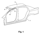
- FIG. 1 shows the lateral part of the body of a motor vehicle comprising an outer side wall 1, the inner A-pillar profile 2 and the roof 3.
- the inner A-pillar profile 2 is welded to the front roof frame 4 in the connection area A.
- Figure 2 shows a known, left-sided, inner A-pillar profile 2 in T-shape.
- FIG. 3 shows the left side, inner A-pillar profile 3 according to the present invention. It has a hat profile, so waives a projecting from the profile longitudinal leg.
- the abutment flange 6 is interrupted and has the inner part 2 of the A-pillar two retaining tabs 7, 7 '.
- the front roof frame profile 4 is inserted from above and comes to rest on the retaining tabs 7,7 '.
- Each of the two retaining tabs 7, 7 ' is then welded to the front roof frame profile 4. By the position of the retaining tabs a height fixation of the roof frame profile 4 is made.
- Fig. 4 shows the connection area A in an enlarged view.
- the retaining tabs 7 and 7 ' are welded at the welding points 12 and 12 with the front roof frame profile.
- the abutment flange 6 is interrupted in the connection area and is additionally lowered in relation to the profile longitudinal direction front and rear. In this recess region, it is thus formed as a retaining pocket 9 or 9 'and welded to the front roof frame profile 4 via the welding points 13 and 13'.
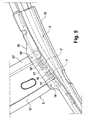
- Figure 5 is a plan view of the connection region corresponding to Figure 4.
- the additional retaining tabs increase the torsional rigidity and reduce the material thickness.
- the retaining tabs 7, 7 ' have, on the end facing away from the inner A-pillar profile part 2, a bevelled end 10, 10', which engages in corresponding through openings 11, 11 'of the front roof frame profile 4.
- the reinforcing plate 15 arranged in the A-pillar 15 can be seen.
- This reinforcing plate 15 no longer follows the profile longitudinal curvature in the connection region, but instead widens toward the roof frame profile 4.
- this tab-shaped widening region 16 of the reinforcing plate 15 extends less than 4 cm, preferably less than 3 cm inwards.
- the reinforcing plate 15 directly, ie in two sheet metal layers, with the abutment flanges 17 and 17 'of the front roof frame profile 4 via welds 14 and 14' are welded. Again, the torsional stiffness can be increased and the material thickness of the inner profile part 2 can be reduced.
Landscapes
- Engineering & Computer Science (AREA)
- Chemical & Material Sciences (AREA)
- Combustion & Propulsion (AREA)
- Transportation (AREA)
- Mechanical Engineering (AREA)
- Body Structure For Vehicles (AREA)
- Rod-Shaped Construction Members (AREA)
- Graft Or Block Polymers (AREA)
- Walking Sticks, Umbrellas, And Fans (AREA)
Abstract
Description
- Die Erfindung bezieht sich auf ein Rahmenseitenteil der Karosserie von Kraftfahrzeugen, auf Karosseriesäulen eines Kraftfahrzeugs und deren innenliegende Profilteile. Eine derartige Karosseriesäule ist bevorzugt eine A-Säule.
- Die A-Säule eines Kraftfahrzeugs besteht aus einem innenliegenden Profilteil, einem äußeren Profilteil als Bestandteil der äußeren Seitenwand, und einer zwischen diesen Profilteilen befindlichen Verstärkung. Der innenliegende Teil der A-Säule benötigt bekanntermaßen eine Profilform, die es ermöglicht, ein vorderes Dachrahmenprofil quer dazu anzulegen um beide Teile zu verschweißen. Beim Zusammenbau der Karosserie wird zunächst das innenliegende Profilteil stehen und mit dem vorderen Dachrahmenprofil verschweißt. Je nach der Zusammenbaufolge des Fahrzeugs wird dann die äußere Seitenwand nebst A-Säulenverstärkung sowie das Dach in zwei oder drei Blechlagen punktgeschweißt.
- Das innenliegende A-Säulenprofil weist im allgemeinen eine T-Form auf, wobei im dreischenkeligen Knotenbereich das vordere Dachrahmenprofil aufgelegt wird. Diese Profilform erfordert einen großen Rohblechzuschnitt und bedingt einen großen Materialabfall. Da weiterhin für diese Profilform nur Stahl mit angepasster minderer Güte verwendet werden kann muss aus Gründen der Front-Crashanforderungen in diesem Bereich die Materialstärke erhöht werden. Die gleiche Anforderung ergibt sich, wenn die Karosserie während der Herstellung am vorderen und hinteren Dachrahmenprofil hochgehoben wird um zu verschiedenen Bearbeitungsstationen bewegt zu werden. Die erhöhte Blechdicke führt jedoch zu einem höheren Gesamtgewicht des Fahrzeugs und zu einem erhöhten Kraftstoffverbrauch.
- Die
EP 1153819 A1 beschreibt ein Karosseriegrundaufbau für Kraftfahrzeuge. Die A-Säule bzw. ihr innenliegendes Profilteil selbst verfügt über keinen Schenke zur Anbindung des vorderen Dachrahmens. Vielmehr sind das innenliegende A-Säulenprofil und die dreischenkelige Knotenverbindung zweistückig ausgebildet. Hierbei besitzt die separate Knotenverbindung eine durch ein Keilstück gebildete Flächenabstufung. Die Flächenabstufung verleiht dem Fahrzeugaufbau einen glatten Anlageflansch, welche durch das Dachrahmenprofil und die Knotenverbindung definiert ist, um für die Windschutzscheibe eine glatte Aufnahmefläche bereitzustellen. Diese Lösung bedingt einen aufwendigen Zusammenbau der Karosserie da insgesamt drei Teile verbaut werden müssen. - Ausgehend vom oben genannten Stand der Technik besteht das der Erfindung zugrunde liegende technische Problem in der Bereitstellung einer Karosseriesäule, insbesondere einer A-Säule, die eine einfachere Verbindung mit dem vorderen Dachrahmenprofil bei verringertem Gewicht ermöglicht.
- Dieses technische Problem wird erfindungsgemäß durch eine Karosseriesäule, insbesondere eine A-Säule für Kraftfahrzeuge, insbesondere Personenkraftwagen, mit den im unabhängigen Anspruch angegebenen Merkmalen gelöst. Vorteilhafte Weiterbildungen werden durch die Unteransprüche wiedergegeben.
- Die nachfolgende Erfindungsbeschreibung bezieht sich zum Zwecke der vereinfachten Darstellung auf die A-Säule eines Kraftfahrzeugs und ihre Anbindung an das vordere Dachrahmenprofil. Der Fachmann wird jedoch erkennen, dass die vorgeschlagene Lösung auch bei einer B-Säule oder einer C-Säule anwendbar ist die mit dem mittleren bzw. hinteren Dachrahmenprofil zu verbinden ist.
- Die erfindungsgemäße Lösung sieht vor, beim innenliegenden Profilteil der A-Säule auf eine dreischenkelige Knotenverbindung zu verzichten und für die Verbindung des innenliegenden A-Säulenprofils mit dem vorderen Dachrahmenprofil mindestens eine aus dem innenliegenden Profilbereich der A-Säule herausgeführte Haltelasche vorzusehen. Die Haltelaschen befinden sich im Anbindungsbereich in dem ansonsten die dreischenkelige Knotenverbindung wäre, d.h. im unterbrochenen Bereich des Anlageflansches des A-Säulenprofils. Zur Befestigung wird das vordere Dachrahmenprofil von oben auf- bzw. eingelegt, kommt flächig auf der Haltelasche zu liegen, und kann anschließend mit dieser verschweißt werden. Über die Position der Haltelaschen wird hierbei die Höhe definiert in der der Dachrahmenprofil zu liegen kommt.
- Das Herausführen der Haltelasche kann dergestalt sein, dass die Haltelasche teilweise aus dem A-Säulenprofil ausgestanzt und dann aus dem Profil herausgedrückt bzw. umgelegt wird. Die Fläche der seitlich nach innen gerichteten Haltelasche ist dabei zur Gewährleistung einer gleichmäßigen Flächenbelastung der Krümmung des endseitigen Abschnitts des vorderen Dachrahmenprofils angepasst bzw. parallel zu dieser. Um höchstens drei zu verschweißende Blechlagen zu gewährleisten können alle strukturschwachen Flansche hierfür freigeschnitten werden.
- Die vorgeschlagene Lösung ermöglicht es wegen der vereinfachten Profilform der A-Säule hochfeste Stähle zu verwenden. Hierdurch können geringere Materialdicken gewählt werden und ergibt sich eine Gewichtsersparnis. Eine weitere Gewichtsersparnis ergibt sich durch den Wegfall der dreischenkeligen Knotenverbindung. Gleichzeitig ergibt sich eine gute Dachknotenstruktur infolge einer steifen Übereckanbindung. Weiterhin bedingt die vereinfachte Profilform eine Materialersparnis wegen eines verringerten Beschnittabfalls in der Herstellung der A-Säule.
- Im Regelfall wird die Wahl einer einzigen Haltelasche zur Aufnahme des vorderen Dachrahmenprofils ausreichend sein. Eine stabilere Anbindung des vorderen Dachrahmenprofils am innenliegenden A-Säulenprofil ergibt sich, wenn neben einer zentralen Haltelasche, welche das vordere Dachrahmenprofil weitgehend mittig aufnimmt, zwei weitere Haltelaschen vorgesehen sind, die sich bezogen auf die Profillängsrichtung vor und nach der zentralen Haltelasche befinden. Alternativ hierzu sind zwei Haltelaschen hintereinander vorgesehen. Das vordere Dachrahmenprofil kommt beim Einlegen in das A-Säulenprofil ebenfalls auf diese zusätzlichen Haltelaschen zu liegen wodurch mehr Schweißverbindungen möglich sind.
- Um eine möglichst exakte Positionierung des vorderen Dachrahmenprofils relativ zum A-Säulenprofils zu gewährleisten ist die Haltelasche bevorzugterweise an ihrem dem A-Säulenprofil abgewandten Ende abgekantet um in eine hierzu korrespondierende durchgehende Öffnung des vorderen Dachrahmenprofils eingreifen zu können.
- Im Anbindungsbereich ist der Anlageflansch des innenliegenden Profilteils unterbrochen um Platz zum Auflegen des Dachrahmenprofils von oben zu haben. Der Anlageflansch ist zudem an den dem Anbindungsbereich zugewandten Enden in bzw. entgegen der Profillängsrichtung abgesenkt. Die dadurch entstehenden rampenförmigen Abschnitte des Anlageflansches stellen zwei weitere Haltelaschen dar mit denen das vordere Dachrahmenprofil verschweißt werden kann. Hierdurch wird die Lage des vorderen Dachrahmenprofils in seitlicher Richtung festgelegt.
- Im Rahmen der Fahrzeugproduktion muss die Karosserie entlang der Fertigungsstationen bewegt werden, wobei oftmals Greifer zum Einsatz kommen, welche das Fahrzeug von oben her aufnehmen. Zwei Aufnahmepunkte sind hierbei dicht benachbart zum Anbindungsbereich. Um hierbei die mechanische Stabilität des Anbindungsbereichs zu verbessern kann die Haltelasche zusätzlich eine durchgehende Öffnung zum Eingriff eines Rastelements des vorderen Dachrahmenprofils aufweisen.
- Weitere Merkmale und Vorteile der Erfindung werden aus der folgenden detaillierten Beschreibung mit Bezug auf die beigefügten Zeichnungen erkennbar die nachfolgend als nicht beschränkende Beispiele gegeben sind. Es stellt dar:
- Fig. 1
- eine perspektivische Seitenansicht einer Kfz-Karosserie
gemäß dem Stand der Technik, - Fig. 2
- eine innenliegende A-Säule nebst vorderem Dachrahmenprofil nach dem Stand der Technik,
- Fig. 3
- eine innere A-Säule in der perspektivischen Seitenansicht,
- Fig. 4
- den Anbindungsbereich A-Säule-vorderes Dachrahmenprofil in der perspektivischen Seitenansicht,
- Fig. 5
- den Anbindungsbereich A-Säule-vorderes Dachrahmenprofil
in der Draufsicht, mit zusätzlicher Anbindung der A-Säulenverstärkung an den Dachrahmen, - Fig. 6
- das Verstärkungsblech für die A-Säule in einer perspektivischen Seitenansicht.
- Die Figur 1 zeigt den seitlichen Teil der Karosserie eines Kraftfahrzeugs umfassend eine äußere Seitenwand 1, das innenliegende A-Säulenprofil 2 und das Dach 3. Das innenliegende A-Säuleprofil 2 ist mit dem vorderen Dachrahmen 4 im Anbindungsbereich A verschweißt.
- Figur 2 zeigt ein bekanntes, linksseitiges, innenliegende A-Säulenprofil 2 in T-Form. Beim Zusammenbau wird der vordere Dachrahmen 4 auf den seitlich abstehenden Schenkel 5 gelegt und geeignet verschweißt.
- Figur 3 zeigt das linksseitige, innenliegende A-Säulenprofil 3 gemäß der vorliegenden Erfindung. Sie weist ein Hutprofil auf, verzichtet also auf einen von der Profillängsrichtung abstehenden Schenkel. Im Anbindungsbereich ist der Anlageflansch 6 unterbrochen und besitzt das innenliegende Teil 2 der A-Säule zwei Haltelaschen 7, 7'. Beim Zusammenbau der Karosserie kommt zuerst der innenliegende Teil 2 zu stehen, wird das vordere Dachrahmenprofil 4 von oben eingelegt und kommt auf den Haltelaschen 7,7' zu liegen. Jede der beiden Haltelaschen 7, 7' wird dann mit dem vorderen Dachrahmenprofil 4 verschweißt. Durch die Position der Haltelaschen wird eine Höhenfixierung des Dachrahmenprofils 4 vorgenommen.
- Fig. 4 zeigt den Anbindungsbereich A in vergrößerter Darstellung. In dieser perspektivischen Seitenansicht erkennt man zwei Öffnungen 8 bzw. 8' im inneren Profilteil 2 der A-Säule, entstanden durch Schwenken der Haltelaschen 7 bzw. 7' um eine durch den Pfeil P angedeutete Achse. Die Haltelaschen 7 und 7' sind an den Schweißpunkten 12 und 12 mit dem vorderen Dachrahmenprofil verschweißt. Der Anlageflansch 6 ist im Anbindungsbereich unterbrochen und ist zusätzlich bezogen auf die Profillängsrichtung vorne und hinten abgesenkt. In diesem Aussparungsbereich ist sie damit als Haltasche 9 bzw. 9' ausgebildet und mit dem vorderen Dachrahmenprofil 4 über die Schweißpunkte 13 und 13' verschweißt.
- Figur 5 ist eine Draufsicht des Anbindungsbereichs entsprechend zu Figur 4. Hier erkennt man erneut die Haltelaschen 7 bzw. 7' auf denen das vordere Dachrahmenprofil 4 zu liegen kommt, und die beiden im wesentlichen senkrecht angeordneten Haltelaschen 9 bzw. 9' im vorderen und hinteren Randbereich des Anlageflansches 6. Durch die zusätzlichen Haltelaschen kann die Torsionssteifigkeit erhöht und die Materialdicke gemindert werden. Die Haltelaschen 7,7' weisen am bezogen auf das innenliegende Ä-Säulenprofilteil 2 abgewandten Ende ein abgekantetes Ende 10,10' auf, welches in korrespondierende durchgehende Öffnungen 11,11' des vorderen Dachrahmenprofils 4 eingreift.
- Weiterhin erkennt man in Figur 5, ergänzend hierzu in Fig. 6, das sich in der A-Säule angeordnete Verstärkungsblech 15. Dieses Verstärkungsblech 15 folgt im Anbindungsbereich nicht mehr der Profillängskrümmung, sondern ist dort zum Dachrahmenprofil 4 hin verbreitert. Bei weiterhin einstückiger Ausbildung erstreckt sich dieser laschenförmige Verbreiterungsbereich 16 des Verstärkungsblechs 15 weniger als 4 cm, bevorzugt weniger als 3 cm nach innen. Damit kann das Verstärkungsblech 15 direkt, d.h. in zwei Blechlagen, mit den Anlageflanschen 17 bzw. 17' des vorderen Dachrahmenprofils 4 über Schweißpunkte 14 bzw. 14' verschweißt werden. Auch hiermit kann die Torsionssteifigkeit erhöht und die Materialdicke des innenliegenden Profilteils 2 gemindert werden.
-
- 01
- äußere Seitenwand
- 02
- innenliegender Profilteil der A-Säule
- 03
- Dach
- 04
- vorderes Dachrahmenprofil
- 05
- abstehender Schenkel
- 06
- Anlageflansch
- 07
- Haltelasche
- 07'
- Haltelasche
- 08
- Öffnung
- 08'
- Öffnung
- 09
- Haltelasche
- 09'
- Haltelasche
- 10
- abgekantetes Ende der Haltelasche
- 10'
- abgekantetes Ende der Haltelasche
- 11
- durchgehende Öffnung
- 11'
- durchgehende Öffnung
- 12
- Schweißpunkt
- 12'
- Schweißpunkt
- 13
- Schweißpunkt
- 13'
- Schweißpunkt
- 14
- Schweißpunkt
- 14'
- Schweißpunkt
- 15
- Verstärkungsblech
- 16
- Verbreiterungsbereich der A-Säulenverstärkung
- 17
- Anlageflansch
- 17'
- Anlageflansch
- A
- Anbindungsbereich
Claims (7)
- Karosseriesäule eines Kraftfahrzeugs, insbesondere A-Säule, mit einem innenliegenden Profilteil (2),
dadurch gekennzeichnet,
dass für das innenliegende Profilteil (2) mindestens eine seitlich nach innen herausgeführte Haltelasche (7,7') zum flächigen Auflegen und Verschweißen des Dachrahmenprofils (4) vorgesehen ist. - Karosseriesäule nach Anspruch 1,
dadurch gekennzeichnet,
dass die Haltelasche aus dem innenliegenden Profilteil herausgedrückt ist. - Karosseriesäule nach Anspruch 1 oder 2,
dadurch gekennzeichnet,
dass neben einer das Dachrahmenprofil weitgehend mittig aufnehmenden Haltelasche zwei weitere Haltelaschen zum Auflegen und Verschweißen des vorderen und hinteren Bereichs des Dachrahmenprofils vorgesehen sind. - Karosseriesäule nach einem der Ansprüche 1 bis 3,
dadurch gekennzeichnet,
dass die Haltelasche an ihrem dem Säulenprofil abgewandten Ende abgekantet ist (10,10') um in eine hierzu korrespondierende durchgehende Öffnung (11,11') des Dachrahmenprofils eingreifen zu können. - Karosseriesäule nach einem der Ansprüche 1 bis 4,
dadurch gekennzeichnet,
dass der Anlageflansch (6) des innenliegenden Profilteils (2) im Anbindungsbereich (A) unterbrochen ist und an den dem Anbindungsbereich zugewandten Enden rampenförmig abgesenkt ist. - Karosseriesäule nach einem der Ansprüche 1 bis 5,
dadurch gekennzeichnet,
dass ihr innenliegendes Profilteil (2) aus einem hochfesten Stahl besteht. - Karosseriesäule nach einem der Ansprüche 1 bis 6,
dadurch gekennzeichnet,
dass sie ein in der Säule angeordnetes Verstärkungsblech (15) besitzt das im Anbindungsbereich laschenförmig nach innen verbreitert ist, sodass es mit dem Dachrahmenprofil direkt verschweißbar ist.
Applications Claiming Priority (1)
| Application Number | Priority Date | Filing Date | Title |
|---|---|---|---|
| DE102005044066A DE102005044066A1 (de) | 2005-09-15 | 2005-09-15 | Karosseriesäule |
Publications (2)
| Publication Number | Publication Date |
|---|---|
| EP1764286A1 true EP1764286A1 (de) | 2007-03-21 |
| EP1764286B1 EP1764286B1 (de) | 2009-11-18 |
Family
ID=37487739
Family Applications (1)
| Application Number | Title | Priority Date | Filing Date |
|---|---|---|---|
| EP06017415A Not-in-force EP1764286B1 (de) | 2005-09-15 | 2006-08-22 | Karosseriesäule |
Country Status (3)
| Country | Link |
|---|---|
| EP (1) | EP1764286B1 (de) |
| AT (1) | ATE448992T1 (de) |
| DE (2) | DE102005044066A1 (de) |
Cited By (1)
| Publication number | Priority date | Publication date | Assignee | Title |
|---|---|---|---|---|
| CN114007929A (zh) * | 2019-06-19 | 2022-02-01 | 标致雪铁龙汽车股份有限公司 | 具有在车顶横梁与车顶拱梁之间的加强零件的机动车辆结构件 |
Families Citing this family (2)
| Publication number | Priority date | Publication date | Assignee | Title |
|---|---|---|---|---|
| DE102008061490B3 (de) * | 2008-12-10 | 2010-08-05 | Thyssenkrupp Drauz Nothelfer Gmbh | Karosserie für ein Kraftfahrzeug und Verfahren zur Herstellung einer Kraftfahrzeugkarosserie |
| JP6973264B2 (ja) * | 2018-04-20 | 2021-11-24 | トヨタ自動車株式会社 | ピラー構造 |
Citations (4)
| Publication number | Priority date | Publication date | Assignee | Title |
|---|---|---|---|---|
| JPH10218018A (ja) | 1997-02-10 | 1998-08-18 | Daihatsu Motor Co Ltd | 自動車の車体の上側部構造 |
| EP1127776A2 (de) | 2000-02-26 | 2001-08-29 | Volkswagen Aktiengesellschaft | Anordnung eines tragenden Bauteils einer Fahrzeugkarosserie |
| DE10302463A1 (de) | 2003-01-23 | 2004-09-02 | Bayerische Motoren Werke Ag | Unlösbare Verbindung, insbesondere Eckverbindung, wenigstens zweier Längsteile einer Kraftfahrzeugkarosserie |
| WO2005021361A1 (de) | 2003-08-27 | 2005-03-10 | Thyssenkrupp Steel Ag | Säule in einer tragstruktur eines kraftfahrzeugs in spaceframe-bauweise |
-
2005
- 2005-09-15 DE DE102005044066A patent/DE102005044066A1/de not_active Withdrawn
-
2006
- 2006-08-22 DE DE502006005388T patent/DE502006005388D1/de active Active
- 2006-08-22 AT AT06017415T patent/ATE448992T1/de active
- 2006-08-22 EP EP06017415A patent/EP1764286B1/de not_active Not-in-force
Patent Citations (4)
| Publication number | Priority date | Publication date | Assignee | Title |
|---|---|---|---|---|
| JPH10218018A (ja) | 1997-02-10 | 1998-08-18 | Daihatsu Motor Co Ltd | 自動車の車体の上側部構造 |
| EP1127776A2 (de) | 2000-02-26 | 2001-08-29 | Volkswagen Aktiengesellschaft | Anordnung eines tragenden Bauteils einer Fahrzeugkarosserie |
| DE10302463A1 (de) | 2003-01-23 | 2004-09-02 | Bayerische Motoren Werke Ag | Unlösbare Verbindung, insbesondere Eckverbindung, wenigstens zweier Längsteile einer Kraftfahrzeugkarosserie |
| WO2005021361A1 (de) | 2003-08-27 | 2005-03-10 | Thyssenkrupp Steel Ag | Säule in einer tragstruktur eines kraftfahrzeugs in spaceframe-bauweise |
Cited By (1)
| Publication number | Priority date | Publication date | Assignee | Title |
|---|---|---|---|---|
| CN114007929A (zh) * | 2019-06-19 | 2022-02-01 | 标致雪铁龙汽车股份有限公司 | 具有在车顶横梁与车顶拱梁之间的加强零件的机动车辆结构件 |
Also Published As
| Publication number | Publication date |
|---|---|
| ATE448992T1 (de) | 2009-12-15 |
| DE102005044066A1 (de) | 2007-04-05 |
| EP1764286B1 (de) | 2009-11-18 |
| DE502006005388D1 (de) | 2009-12-31 |
Similar Documents
| Publication | Publication Date | Title |
|---|---|---|
| DE102010036450B4 (de) | B-Säulenverstärkung eines Kraftfahrzeugs | |
| DE60221416T2 (de) | Modularer unterboden für ein kraftfahrzeug | |
| EP1118528B1 (de) | Karosserieelement mit Verstärkungsblech | |
| EP3022086B1 (de) | Rückenlehnenstruktur für einen fahrzeugsitz und fahrzeugsitz | |
| DE102016223216A1 (de) | Karosserie-Bodenstruktur für ein Fahrzeug | |
| DE102009044417A1 (de) | Profil und Verfahren zu dessen Herstellung | |
| DE202014101186U1 (de) | Hydrogeformte Verstärkung vom Dachpaneel zu einer Seitensäule für Fahrzeuge | |
| EP1764286B1 (de) | Karosseriesäule | |
| DE102005050617A1 (de) | Baugruppe für Fahrzeuge und ein Verfahren zum Herstellen derselben | |
| EP1055587B1 (de) | Mehrteilige Stirnwand für eine Kraftfahrzeugrohbaukarosserie | |
| DE102005011834B4 (de) | Seitlicher Dachrahmen für ein Kraftfahrzeug | |
| EP1172281A1 (de) | A-Säulengestaltung eines Personenkraftwagens und Verfahren zur Herstellung einer A-Säule | |
| EP1863697B1 (de) | Kraftfahrzeug mit einem seitenschweller | |
| EP1764287B1 (de) | Karosseriesäule eines Kraftfahrzeugs, seitlicher Dachkanal und dreischenkelige Knotenverbindung | |
| DE102010060702A1 (de) | A-Säule für eine Karosserie eines Kraftfahrzeuges | |
| DE102009007035A1 (de) | Bodenblech für ein Kraftfahrzeug und Verfahren zu seiner Herstellung | |
| DE102008054159A1 (de) | Verfahren zum Herstellen einer Klemmleiste | |
| DE102013002306A1 (de) | Fahrzeugsäule, insbesondere B-Säule eines Kraftfahrzeuges | |
| DE102016013301A1 (de) | Fahrzeugsäule für ein Kraftfahrzeug und Verfahren zum Herstellen einer Fahrzeugsäule für ein Kraftfahrzeug | |
| EP0577235B1 (de) | Hohlprofil für die Verstärkung einer Kraftfahrzeugtür | |
| EP3450041B1 (de) | Verfahren zur herstellung eines rohrförmigen hohlkörpers aus einer zugeschnittenen metallischen platine und fahrwerks- oder karosseriebauteil mit einem nach dem verfahren hergestellten hohlkörper | |
| DE102004013511A1 (de) | Karosseriesäule | |
| DE102017201063B4 (de) | Karosserie-Bodenstruktur für ein zweispuriges Fahrzeug | |
| DE102021123788B4 (de) | Kraftfahrzeug-Biegeträger | |
| EP1127776A2 (de) | Anordnung eines tragenden Bauteils einer Fahrzeugkarosserie |
Legal Events
| Date | Code | Title | Description |
|---|---|---|---|
| PUAI | Public reference made under article 153(3) epc to a published international application that has entered the european phase |
Free format text: ORIGINAL CODE: 0009012 |
|
| AK | Designated contracting states |
Kind code of ref document: A1 Designated state(s): AT BE BG CH CY CZ DE DK EE ES FI FR GB GR HU IE IS IT LI LT LU LV MC NL PL PT RO SE SI SK TR |
|
| AX | Request for extension of the european patent |
Extension state: AL BA HR MK YU |
|
| 17P | Request for examination filed |
Effective date: 20070709 |
|
| 17Q | First examination report despatched |
Effective date: 20070813 |
|
| AKX | Designation fees paid |
Designated state(s): AT BE BG CH CY CZ DE DK EE ES FI FR GB GR HU IE IS IT LI LT LU LV MC NL PL PT RO SE SI SK TR |
|
| GRAP | Despatch of communication of intention to grant a patent |
Free format text: ORIGINAL CODE: EPIDOSNIGR1 |
|
| GRAS | Grant fee paid |
Free format text: ORIGINAL CODE: EPIDOSNIGR3 |
|
| GRAA | (expected) grant |
Free format text: ORIGINAL CODE: 0009210 |
|
| AK | Designated contracting states |
Kind code of ref document: B1 Designated state(s): AT BE BG CH CY CZ DE DK EE ES FI FR GB GR HU IE IS IT LI LT LU LV MC NL PL PT RO SE SI SK TR |
|
| REG | Reference to a national code |
Ref country code: GB Ref legal event code: FG4D Free format text: NOT ENGLISH |
|
| REG | Reference to a national code |
Ref country code: CH Ref legal event code: EP |
|
| REG | Reference to a national code |
Ref country code: IE Ref legal event code: FG4D |
|
| REF | Corresponds to: |
Ref document number: 502006005388 Country of ref document: DE Date of ref document: 20091231 Kind code of ref document: P |
|
| REG | Reference to a national code |
Ref country code: NL Ref legal event code: VDEP Effective date: 20091118 |
|
| LTIE | Lt: invalidation of european patent or patent extension |
Effective date: 20091118 |
|
| PG25 | Lapsed in a contracting state [announced via postgrant information from national office to epo] |
Ref country code: SE Free format text: LAPSE BECAUSE OF FAILURE TO SUBMIT A TRANSLATION OF THE DESCRIPTION OR TO PAY THE FEE WITHIN THE PRESCRIBED TIME-LIMIT Effective date: 20091118 Ref country code: PT Free format text: LAPSE BECAUSE OF FAILURE TO SUBMIT A TRANSLATION OF THE DESCRIPTION OR TO PAY THE FEE WITHIN THE PRESCRIBED TIME-LIMIT Effective date: 20100318 Ref country code: FI Free format text: LAPSE BECAUSE OF FAILURE TO SUBMIT A TRANSLATION OF THE DESCRIPTION OR TO PAY THE FEE WITHIN THE PRESCRIBED TIME-LIMIT Effective date: 20091118 Ref country code: IS Free format text: LAPSE BECAUSE OF FAILURE TO SUBMIT A TRANSLATION OF THE DESCRIPTION OR TO PAY THE FEE WITHIN THE PRESCRIBED TIME-LIMIT Effective date: 20100318 Ref country code: LT Free format text: LAPSE BECAUSE OF FAILURE TO SUBMIT A TRANSLATION OF THE DESCRIPTION OR TO PAY THE FEE WITHIN THE PRESCRIBED TIME-LIMIT Effective date: 20091118 Ref country code: ES Free format text: LAPSE BECAUSE OF FAILURE TO SUBMIT A TRANSLATION OF THE DESCRIPTION OR TO PAY THE FEE WITHIN THE PRESCRIBED TIME-LIMIT Effective date: 20100228 |
|
| PG25 | Lapsed in a contracting state [announced via postgrant information from national office to epo] |
Ref country code: PL Free format text: LAPSE BECAUSE OF FAILURE TO SUBMIT A TRANSLATION OF THE DESCRIPTION OR TO PAY THE FEE WITHIN THE PRESCRIBED TIME-LIMIT Effective date: 20091118 Ref country code: SI Free format text: LAPSE BECAUSE OF FAILURE TO SUBMIT A TRANSLATION OF THE DESCRIPTION OR TO PAY THE FEE WITHIN THE PRESCRIBED TIME-LIMIT Effective date: 20091118 Ref country code: LV Free format text: LAPSE BECAUSE OF FAILURE TO SUBMIT A TRANSLATION OF THE DESCRIPTION OR TO PAY THE FEE WITHIN THE PRESCRIBED TIME-LIMIT Effective date: 20091118 Ref country code: CY Free format text: LAPSE BECAUSE OF FAILURE TO SUBMIT A TRANSLATION OF THE DESCRIPTION OR TO PAY THE FEE WITHIN THE PRESCRIBED TIME-LIMIT Effective date: 20091118 |
|
| REG | Reference to a national code |
Ref country code: IE Ref legal event code: FD4D |
|
| PG25 | Lapsed in a contracting state [announced via postgrant information from national office to epo] |
Ref country code: RO Free format text: LAPSE BECAUSE OF FAILURE TO SUBMIT A TRANSLATION OF THE DESCRIPTION OR TO PAY THE FEE WITHIN THE PRESCRIBED TIME-LIMIT Effective date: 20091118 Ref country code: BG Free format text: LAPSE BECAUSE OF FAILURE TO SUBMIT A TRANSLATION OF THE DESCRIPTION OR TO PAY THE FEE WITHIN THE PRESCRIBED TIME-LIMIT Effective date: 20100218 Ref country code: DK Free format text: LAPSE BECAUSE OF FAILURE TO SUBMIT A TRANSLATION OF THE DESCRIPTION OR TO PAY THE FEE WITHIN THE PRESCRIBED TIME-LIMIT Effective date: 20091118 Ref country code: EE Free format text: LAPSE BECAUSE OF FAILURE TO SUBMIT A TRANSLATION OF THE DESCRIPTION OR TO PAY THE FEE WITHIN THE PRESCRIBED TIME-LIMIT Effective date: 20091118 Ref country code: NL Free format text: LAPSE BECAUSE OF FAILURE TO SUBMIT A TRANSLATION OF THE DESCRIPTION OR TO PAY THE FEE WITHIN THE PRESCRIBED TIME-LIMIT Effective date: 20091118 Ref country code: IE Free format text: LAPSE BECAUSE OF FAILURE TO SUBMIT A TRANSLATION OF THE DESCRIPTION OR TO PAY THE FEE WITHIN THE PRESCRIBED TIME-LIMIT Effective date: 20091118 |
|
| PG25 | Lapsed in a contracting state [announced via postgrant information from national office to epo] |
Ref country code: CZ Free format text: LAPSE BECAUSE OF FAILURE TO SUBMIT A TRANSLATION OF THE DESCRIPTION OR TO PAY THE FEE WITHIN THE PRESCRIBED TIME-LIMIT Effective date: 20091118 Ref country code: SK Free format text: LAPSE BECAUSE OF FAILURE TO SUBMIT A TRANSLATION OF THE DESCRIPTION OR TO PAY THE FEE WITHIN THE PRESCRIBED TIME-LIMIT Effective date: 20091118 |
|
| PLBE | No opposition filed within time limit |
Free format text: ORIGINAL CODE: 0009261 |
|
| STAA | Information on the status of an ep patent application or granted ep patent |
Free format text: STATUS: NO OPPOSITION FILED WITHIN TIME LIMIT |
|
| 26N | No opposition filed |
Effective date: 20100819 |
|
| PG25 | Lapsed in a contracting state [announced via postgrant information from national office to epo] |
Ref country code: GR Free format text: LAPSE BECAUSE OF FAILURE TO SUBMIT A TRANSLATION OF THE DESCRIPTION OR TO PAY THE FEE WITHIN THE PRESCRIBED TIME-LIMIT Effective date: 20100219 |
|
| BERE | Be: lapsed |
Owner name: GM GLOBAL TECHNOLOGY OPERATIONS, INC. Effective date: 20100831 |
|
| PG25 | Lapsed in a contracting state [announced via postgrant information from national office to epo] |
Ref country code: IT Free format text: LAPSE BECAUSE OF FAILURE TO SUBMIT A TRANSLATION OF THE DESCRIPTION OR TO PAY THE FEE WITHIN THE PRESCRIBED TIME-LIMIT Effective date: 20091118 Ref country code: MC Free format text: LAPSE BECAUSE OF NON-PAYMENT OF DUE FEES Effective date: 20100831 |
|
| REG | Reference to a national code |
Ref country code: CH Ref legal event code: PL |
|
| PG25 | Lapsed in a contracting state [announced via postgrant information from national office to epo] |
Ref country code: LI Free format text: LAPSE BECAUSE OF NON-PAYMENT OF DUE FEES Effective date: 20100831 Ref country code: CH Free format text: LAPSE BECAUSE OF NON-PAYMENT OF DUE FEES Effective date: 20100831 |
|
| REG | Reference to a national code |
Ref country code: DE Ref legal event code: R081 Ref document number: 502006005388 Country of ref document: DE Owner name: GM GLOBAL TECHNOLOGY OPERATIONS LLC (N. D. GES, US Free format text: FORMER OWNER: GM GLOBAL TECHNOLOGY OPERATIONS, INC., DETROIT, US Effective date: 20110323 |
|
| PG25 | Lapsed in a contracting state [announced via postgrant information from national office to epo] |
Ref country code: BE Free format text: LAPSE BECAUSE OF NON-PAYMENT OF DUE FEES Effective date: 20100831 |
|
| PG25 | Lapsed in a contracting state [announced via postgrant information from national office to epo] |
Ref country code: HU Free format text: LAPSE BECAUSE OF FAILURE TO SUBMIT A TRANSLATION OF THE DESCRIPTION OR TO PAY THE FEE WITHIN THE PRESCRIBED TIME-LIMIT Effective date: 20100519 Ref country code: LU Free format text: LAPSE BECAUSE OF NON-PAYMENT OF DUE FEES Effective date: 20100822 |
|
| PG25 | Lapsed in a contracting state [announced via postgrant information from national office to epo] |
Ref country code: TR Free format text: LAPSE BECAUSE OF FAILURE TO SUBMIT A TRANSLATION OF THE DESCRIPTION OR TO PAY THE FEE WITHIN THE PRESCRIBED TIME-LIMIT Effective date: 20091118 |
|
| REG | Reference to a national code |
Ref country code: AT Ref legal event code: MM01 Ref document number: 448992 Country of ref document: AT Kind code of ref document: T Effective date: 20110822 |
|
| PGFP | Annual fee paid to national office [announced via postgrant information from national office to epo] |
Ref country code: DE Payment date: 20120816 Year of fee payment: 7 |
|
| PG25 | Lapsed in a contracting state [announced via postgrant information from national office to epo] |
Ref country code: AT Free format text: LAPSE BECAUSE OF NON-PAYMENT OF DUE FEES Effective date: 20110822 |
|
| PG25 | Lapsed in a contracting state [announced via postgrant information from national office to epo] |
Ref country code: DE Free format text: LAPSE BECAUSE OF NON-PAYMENT OF DUE FEES Effective date: 20140301 |
|
| REG | Reference to a national code |
Ref country code: DE Ref legal event code: R119 Ref document number: 502006005388 Country of ref document: DE Effective date: 20140301 |
|
| REG | Reference to a national code |
Ref country code: FR Ref legal event code: PLFP Year of fee payment: 11 |
|
| PGFP | Annual fee paid to national office [announced via postgrant information from national office to epo] |
Ref country code: GB Payment date: 20160817 Year of fee payment: 11 |
|
| PGFP | Annual fee paid to national office [announced via postgrant information from national office to epo] |
Ref country code: FR Payment date: 20160712 Year of fee payment: 11 |
|
| GBPC | Gb: european patent ceased through non-payment of renewal fee |
Effective date: 20170822 |
|
| REG | Reference to a national code |
Ref country code: FR Ref legal event code: ST Effective date: 20180430 |
|
| PG25 | Lapsed in a contracting state [announced via postgrant information from national office to epo] |
Ref country code: GB Free format text: LAPSE BECAUSE OF NON-PAYMENT OF DUE FEES Effective date: 20170822 |
|
| PG25 | Lapsed in a contracting state [announced via postgrant information from national office to epo] |
Ref country code: FR Free format text: LAPSE BECAUSE OF NON-PAYMENT OF DUE FEES Effective date: 20170831 |