EP1764226B1 - Dispostif et méthode d'alignement automatique de rangés d'éléments d'impression - Google Patents
Dispostif et méthode d'alignement automatique de rangés d'éléments d'impression Download PDFInfo
- Publication number
- EP1764226B1 EP1764226B1 EP05108660A EP05108660A EP1764226B1 EP 1764226 B1 EP1764226 B1 EP 1764226B1 EP 05108660 A EP05108660 A EP 05108660A EP 05108660 A EP05108660 A EP 05108660A EP 1764226 B1 EP1764226 B1 EP 1764226B1
- Authority
- EP
- European Patent Office
- Prior art keywords
- printing
- print head
- alignment
- array
- alignment adjustment
- Prior art date
- Legal status (The legal status is an assumption and is not a legal conclusion. Google has not performed a legal analysis and makes no representation as to the accuracy of the status listed.)
- Active
Links
- 238000007639 printing Methods 0.000 title claims abstract description 200
- 238000000034 method Methods 0.000 title claims abstract description 66
- 238000003491 array Methods 0.000 title description 41
- 238000012360 testing method Methods 0.000 claims abstract description 48
- 238000007641 inkjet printing Methods 0.000 claims description 13
- 239000002609 medium Substances 0.000 description 43
- 230000008569 process Effects 0.000 description 28
- 238000012937 correction Methods 0.000 description 27
- 230000005484 gravity Effects 0.000 description 14
- 230000002457 bidirectional effect Effects 0.000 description 12
- 239000011159 matrix material Substances 0.000 description 8
- 230000003287 optical effect Effects 0.000 description 7
- 230000008901 benefit Effects 0.000 description 4
- 238000004364 calculation method Methods 0.000 description 4
- 239000003086 colorant Substances 0.000 description 4
- 230000000007 visual effect Effects 0.000 description 4
- 238000012935 Averaging Methods 0.000 description 3
- 230000000712 assembly Effects 0.000 description 3
- 238000000429 assembly Methods 0.000 description 3
- 238000013461 design Methods 0.000 description 3
- 230000000694 effects Effects 0.000 description 3
- 239000000463 material Substances 0.000 description 3
- 239000000203 mixture Substances 0.000 description 3
- 239000000123 paper Substances 0.000 description 3
- 239000000758 substrate Substances 0.000 description 3
- 230000004913 activation Effects 0.000 description 2
- 230000008021 deposition Effects 0.000 description 2
- 238000001514 detection method Methods 0.000 description 2
- 238000005516 engineering process Methods 0.000 description 2
- 238000012423 maintenance Methods 0.000 description 2
- 238000004519 manufacturing process Methods 0.000 description 2
- 238000005259 measurement Methods 0.000 description 2
- 230000007246 mechanism Effects 0.000 description 2
- 238000012545 processing Methods 0.000 description 2
- 230000035945 sensitivity Effects 0.000 description 2
- 238000013519 translation Methods 0.000 description 2
- 238000009736 wetting Methods 0.000 description 2
- 238000003848 UV Light-Curing Methods 0.000 description 1
- 239000000853 adhesive Substances 0.000 description 1
- 230000001070 adhesive effect Effects 0.000 description 1
- 238000004458 analytical method Methods 0.000 description 1
- 230000015572 biosynthetic process Effects 0.000 description 1
- 239000012482 calibration solution Substances 0.000 description 1
- 239000011111 cardboard Substances 0.000 description 1
- 238000004140 cleaning Methods 0.000 description 1
- 230000001010 compromised effect Effects 0.000 description 1
- 238000010276 construction Methods 0.000 description 1
- 230000001186 cumulative effect Effects 0.000 description 1
- 230000001419 dependent effect Effects 0.000 description 1
- 238000006073 displacement reaction Methods 0.000 description 1
- 238000001035 drying Methods 0.000 description 1
- 230000005684 electric field Effects 0.000 description 1
- 239000012526 feed medium Substances 0.000 description 1
- 239000011888 foil Substances 0.000 description 1
- 238000005286 illumination Methods 0.000 description 1
- 238000010191 image analysis Methods 0.000 description 1
- 238000003384 imaging method Methods 0.000 description 1
- 238000011065 in-situ storage Methods 0.000 description 1
- 230000003993 interaction Effects 0.000 description 1
- 238000002372 labelling Methods 0.000 description 1
- 238000012986 modification Methods 0.000 description 1
- 230000004048 modification Effects 0.000 description 1
- 230000004044 response Effects 0.000 description 1
- 238000005070 sampling Methods 0.000 description 1
- 239000000243 solution Substances 0.000 description 1
Images


Classifications
-
- B—PERFORMING OPERATIONS; TRANSPORTING
- B41—PRINTING; LINING MACHINES; TYPEWRITERS; STAMPS
- B41J—TYPEWRITERS; SELECTIVE PRINTING MECHANISMS, i.e. MECHANISMS PRINTING OTHERWISE THAN FROM A FORME; CORRECTION OF TYPOGRAPHICAL ERRORS
- B41J2/00—Typewriters or selective printing mechanisms characterised by the printing or marking process for which they are designed
- B41J2/005—Typewriters or selective printing mechanisms characterised by the printing or marking process for which they are designed characterised by bringing liquid or particles selectively into contact with a printing material
- B41J2/01—Ink jet
- B41J2/21—Ink jet for multi-colour printing
- B41J2/2132—Print quality control characterised by dot disposition, e.g. for reducing white stripes or banding
- B41J2/2135—Alignment of dots
-
- B—PERFORMING OPERATIONS; TRANSPORTING
- B41—PRINTING; LINING MACHINES; TYPEWRITERS; STAMPS
- B41J—TYPEWRITERS; SELECTIVE PRINTING MECHANISMS, i.e. MECHANISMS PRINTING OTHERWISE THAN FROM A FORME; CORRECTION OF TYPOGRAPHICAL ERRORS
- B41J25/00—Actions or mechanisms not otherwise provided for
- B41J25/001—Mechanisms for bodily moving print heads or carriages parallel to the paper surface
-
- H—ELECTRICITY
- H04—ELECTRIC COMMUNICATION TECHNIQUE
- H04N—PICTORIAL COMMUNICATION, e.g. TELEVISION
- H04N1/00—Scanning, transmission or reproduction of documents or the like, e.g. facsimile transmission; Details thereof
- H04N1/00002—Diagnosis, testing or measuring; Detecting, analysing or monitoring not otherwise provided for
- H04N1/00007—Diagnosis, testing or measuring; Detecting, analysing or monitoring not otherwise provided for relating to particular apparatus or devices
- H04N1/00015—Reproducing apparatus
-
- H—ELECTRICITY
- H04—ELECTRIC COMMUNICATION TECHNIQUE
- H04N—PICTORIAL COMMUNICATION, e.g. TELEVISION
- H04N1/00—Scanning, transmission or reproduction of documents or the like, e.g. facsimile transmission; Details thereof
- H04N1/00002—Diagnosis, testing or measuring; Detecting, analysing or monitoring not otherwise provided for
- H04N1/00026—Methods therefor
- H04N1/00031—Testing, i.e. determining the result of a trial
-
- H—ELECTRICITY
- H04—ELECTRIC COMMUNICATION TECHNIQUE
- H04N—PICTORIAL COMMUNICATION, e.g. TELEVISION
- H04N1/00—Scanning, transmission or reproduction of documents or the like, e.g. facsimile transmission; Details thereof
- H04N1/00002—Diagnosis, testing or measuring; Detecting, analysing or monitoring not otherwise provided for
- H04N1/00026—Methods therefor
- H04N1/00045—Methods therefor using a reference pattern designed for the purpose, e.g. a test chart
-
- H—ELECTRICITY
- H04—ELECTRIC COMMUNICATION TECHNIQUE
- H04N—PICTORIAL COMMUNICATION, e.g. TELEVISION
- H04N1/00—Scanning, transmission or reproduction of documents or the like, e.g. facsimile transmission; Details thereof
- H04N1/00002—Diagnosis, testing or measuring; Detecting, analysing or monitoring not otherwise provided for
- H04N1/00026—Methods therefor
- H04N1/00053—Methods therefor out of service, i.e. outside of normal operation
-
- H—ELECTRICITY
- H04—ELECTRIC COMMUNICATION TECHNIQUE
- H04N—PICTORIAL COMMUNICATION, e.g. TELEVISION
- H04N1/00—Scanning, transmission or reproduction of documents or the like, e.g. facsimile transmission; Details thereof
- H04N1/00002—Diagnosis, testing or measuring; Detecting, analysing or monitoring not otherwise provided for
- H04N1/00026—Methods therefor
- H04N1/00063—Methods therefor using at least a part of the apparatus itself, e.g. self-testing
-
- H—ELECTRICITY
- H04—ELECTRIC COMMUNICATION TECHNIQUE
- H04N—PICTORIAL COMMUNICATION, e.g. TELEVISION
- H04N1/00—Scanning, transmission or reproduction of documents or the like, e.g. facsimile transmission; Details thereof
- H04N1/00002—Diagnosis, testing or measuring; Detecting, analysing or monitoring not otherwise provided for
- H04N1/00071—Diagnosis, testing or measuring; Detecting, analysing or monitoring not otherwise provided for characterised by the action taken
- H04N1/00082—Adjusting or controlling
- H04N1/00087—Setting or calibrating
Definitions
- the present invention relates to a solution for automatically aligning one or more arrays of printing elements in a printing apparatus. More specifically the invention is related to the automatic alignment of ink jet print heads in an ink jet printing system.
- Inkjet printing is a non-impact method for producing images by the deposition of ink droplets in a pixel-by-pixel manner into an image-recording element in response to digital signals.
- drop-on-demand inkjet printing individual droplets are ejected as needed on to the recording medium to form the desired image.
- Common methods of controlling the ejection of ink droplets in drop-on-demand printing include piezoelectric transducers and thermal bubble formation using heated actuators.
- a heater placed at a convenient location within the nozzle or at the nozzle opening heats ink in selected nozzles and causes a drop to be ejected to the recording medium in those nozzle selected in accordance with image data.
- piezoelectric actuators piezoelectric material is used in conjunction with each nozzle and this material possesses the property such that an electrical field when applied thereto induces mechanical stresses therein causing a drop to be selectively ejected from the nozzle selected for actuation.
- the image data provided as signals to the print head determines which of the nozzles are to be selected for ejection of a respective drop from each nozzle at a particular pixel location on a receiver sheet.
- a continuous stream of droplets is discharged from each nozzle and deflected in an imagewise controlled manner onto respective pixel locations on the surface of the recording member, while some droplets are selectively caught and prevented from reaching the recording member.
- Inkjet printers have found broad applications across markets ranging from the desktop document and pictorial imaging to short run printing and industrial labeling.
- a typical inkjet printer reproduces an image by ejecting small drops of ink from the print head containing an array of spaced apart nozzles, and the ink drops land on a receiver medium (typically paper, coated paper, etc.) at selected pixel locations to form round ink dots.
- the drops are deposited with their respective dot centers on a grid or raster, with fixed spacing in the horizontal and vertical directions between grid or raster points.
- the inkjet printers may have the capability to either produce only dots of the same size or of variable size. Inkjet printers with the latter capability are referred to as (multitone) or gray scale inkjet printers because they can produce multiple density tones at each selected pixel location on the page.
- Inkjet printers may also be distinguished as being either pagewidth printers or swath (scanning) printers.
- Pagewidth printers are equipped with a pagewidth print head or print head assembly being able of printing one line at a time across the full width of a page. The line is printed as a whole as the page moves past the pagewidth print head while the print head is stationary.
- Pagewidth printers are also referred to as single pass printers because the image area is printed in only one pass of the page past the print head.
- An example of a pagewidth printer is the :.Factory printer commercially available from Agfa-Gevaert NV (Belgium). Swath printers on the other hand use multiple passes to print an image.
- a swath of the image is printed on the page.
- the width of a swath typically is linked to the print width of the print head or print head assembly used for printing the swath while passing across the page. Between such passes the page is advanced relative to position of the print head so that a next pass of the print head across the page prints a next swath of the image next to or (partially) overlapping the already printed swath.
- swath printers a print head is traversed in a fast scan direction during a pass across the page to be printed. Often the traversal is such as to be perpendicular to the direction of the arrangement of the array of nozzles of the print head.
- Print heads or print head assemblies used in both pagewidth printers and swath printers may comprise multiple arrays of nozzles mounted together as a single module in a print head or print head assembly.
- the arrays may be arranged in an interleaved position along the fast scan direction to increase print resolution or may be arranged to abut each other to increase the print (swath) width of the print head.
- the arrays may be arranged after each other with their respective nozzles in line with each other along the print direction.
- the first arrangements are often used to create improved monochrome print head assemblies, whereas the latter arrangement is often used in the design of multicolor print head assemblies.
- the dots printed by one nozzle array must be aligned such that they are closely registered relative to the dots printed by the other nozzle arrays. If they are not well registered, then the maximum density attainable by the printer will be compromised, banding artifacts will appear and inferior color registration will lead to blurry or noisy images and overall loss of detail.
- These problems make good registration and alignment of all the nozzle arrays within an inkjet printer critical to ensure good image quality. That is, not only should a nozzle array be well registered with another that jets the same color ink, but it should be well registered with nozzle arrays that jet ink of another color.
- Some high-end printers accept a variety of ink-receiving materials that may differ significantly in thickness.
- the printer may have several allowable discrete gaps between the nozzle arrays and the printer platen to accommodate these different receivers.
- the gap between the nozzle arrays and the top of the receiver referred to as the throw-distance
- the throw-distance can vary significantly because of the range of receiver thicknesses and the limited number of discrete nozzle array heights. Due to the carriage velocity, the flight path of the drop is not straight down but really is the vector sum of the drop velocity and carriage velocity. This angular path and the differences in throw-distance make nozzle array registration sensitive to both the average of throw-distance as well as the variation in the throw-distance. These sensitivities further complicate the nozzle array alignment process.
- carriage velocities implies the supporting of the print heads upon a carriage support that moves in the fast-scan direction while being supported for movement by a rail or other support.
- the angular flight path of the droplets described will be a function of the carriage velocity. This then makes nozzle array alignment sensitive to yet another variable, namely carriage velocity.
- Visual techniques use patterns printed by the printer that permit a user to simultaneously view various alignment settings and choose the best setting. Visual techniques are disadvantaged in many ways. First, for a printer with many nozzle arrays (24 separate nozzle arrays is not uncommon), multiple throw-distances, and multiple carriage velocities, the number of alignments can become overbearing as each variation adds multiplicatively to the rest. Secondly, only a moderate level of accuracy is attainable with most of these techniques and finely tuned printers require a higher degree of accuracy than is attainable by most of these techniques. Thirdly, interactions can occur between the various alignment parameters, which further degrade the ultimate quality of alignment that can be obtained through these visual techniques, or multiple iterations are required, thereby increasing the labor of the effort.
- U.S. Patent Application No. 2002/0126169 discloses an inkjet printer including pagewidth printheads mounted in a frame, wherein the printheads are coupled to mechanical devices for aligning the printheads with respect to each other, with respect to an edge of the images receiving substrate, or with respect to both.
- the printer may include devices for sensing the possible misalignment, coupled to a computer for automatically aligning the printheads.
- the alignment adjustment tool may be positioned in x, y and z direction relative to the alignment adjustment means associated with the array of printing elements of which the alignment needs to be adjusted, and automatically adjusts the alignment of the array of printing elements based on a calculated calibration value derived from processing of the printed calibration test pattern.
- the alignment adjustment tool comprised an automatic screwdriver.
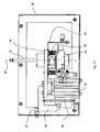
- a digital printer embodying the invention is shown in figure 1 .
- the digital printer 1 comprises a printing table 2 to support a printing medium 3 during digital printing.
- the term printing medium is equivalent to terms like printing substrate or receiver, also frequently used in the literature on printing.
- the printing table is substantially flat and can support flexible sheeted media with a thickness down to tens of micrometers (e.g. paper, transparency foils, adhesive PVC sheets, etc.), as well as rigid substrates with a thickness up to some centimeters (e.g. hard board, PVC, carton, etc.).
- a print head shuttle 4 comprising one or more print heads, is designed for reciprocating back and forth across the printing table in a fast scan direction FS and for repositioning across the printing table in a slow scan direction SS perpendicular to the fast scan direction. Printing is done during the movement of the print head shuttle in the fast scan direction. Repositioning of the print head shuttle in the slow scan direction, in order to position the print heads in line with non-printed or only partially printed areas of the printing medium, is done in between fast scans of the print head shuttle. This repositioning may also be used in situations where the print head shuttle is equipped to print a full-width printing medium in a single fast scan operation, e.g. when using print quality enhancement techniques like shingling methods.
- a support frame 5 guides and supports the print head shuttle during its reciprocating operation.
- a printing medium transport system can feed individual printing sheets into the digital printer along a sheet feeding direction FF that is substantially perpendicular to the fast scan direction of the print head shuttle, as shown in figure 1 .
- the printing medium transport system is designed as a "tunnel" or "guide through” through the digital printer, i.e. it can feed media from one side of the printer (the input end in figure 1 ), position the sheet on the printing table for printing, and remove the sheet from the printer at the opposite side (the discharge end in figure 1 ).
- the digital printer may also be used with a web-based medium transport system.
- the printing medium transport may feed web media into the digital printer from a roll-off at the input end of the digital printer to a roll-on at the discharge end of the digital printer.
- the web is transported along the printing table that is used to support the printing medium during printing.
- the repositioning of the print head shuttle along the slow scan direction may be replaced by a repositioning of the web in the feeding direction.
- the print head shuttle then only reciprocates back and forth across the web in the fast scan direction.
- the print head shuttle in the exemplary embodiment of the digital printer is guided and supported by a support frame.
- the support frame is a double beam construction that supports the print head shuttle at each end and along the full length of the fast scan movement.
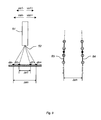
- a print head shuttle that may be used in the digital printer of figure 1 is shown in figure 2 .
- the print head shuttle 4 has a central bridge 41 between a left supporting end 42 and a right supporting end 43.
- a print head carriage 44 is hanging underneath the bridge 41.
- the print head carriage is divided into a front part 45 and a rear part 46.
- the carriage is provided with print head locations 49 for mounting a total of 64 print heads in a matrix of 4 by 16, i.e.
- the 64 print head locations are equally spread over the front part and rear part of the carriage.
- the print head locations in the fast scan direction i.e. the four locations in line, may be used to simultaneously print four colors in a single fast scan movement of the print head shuttle, e.g. to print full process colors in one pass by simultaneously printing of a Cyan, Magenta, Yellow and blacK color.
- the sixteen print head locations next to each other along the slow scan direction allow the print head shuttle to span a substantial width of the printing table, preferably the full width of the printing table to allow a complete printing sheets to be printed in only a few fast scan movements.
- the width of the print head carriage along the x-direction is about 2 m.
- the depth along the y-direction of the print head carriage is about 0,5 m.
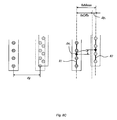
- Print head positioning devices 10 as described in European patent application number 04106837 , published as EP1674279 .
- Figure 3 is taken from this patent application.
- the print head positioning device will be further referred to as the 'HPD'.
- the HPD uses print heads having a z-datum as a mechanical reference to define the print head's z-position relative to a mounting base.
- the print head is inserted in the HPD along the direction of arrow I and fixed in the Z-direction using splines fitting in the grooves 11.
- the associated splines move downward and push the print head's z-datum against a mounting base plate 14 which is part of the print head carriage and is common for all print heads.
- the base plate has cutouts at the print head locations for running through the front part of the print head so that the printing elements of the print head extend through the base plate.
- the HPD's are movably mounted on the base plate by means of slide blocks 9 (see figure 4 ), in a way that the base plate is sandwiched between the HPD and the slide block. The slide block pulls the HPD towards the base plate and is attached to the HPD using four spring-loaded screws 8.
- the spring-loaded screws control the friction force between the HPD and the base plate.
- the HPD may translate relatively to the base plate in the x-direction to align print heads in the print head carriage relative to each other, and may rotate in the xy-plane to position the array of printing elements of the print heads substantially perpendicular to the fast scan direction.
- the translation and rotation of the HPD, relative to the base plate, are indicated by the arrows T and R on figure 3 .
- the translation of the HPD along the x-direction is realized by means of adjustment screw 32 and lever system 30-31, acting upon a datum in the base plate and against anti-play spring 15.
- the rotation of the HP in the xy-plane is performed by means of adjustment screw 22 and lever system 20-21, acting upon another datum in the base plate and against anti-play spring 16.
- the adjustment screws may be operable from the back of the HPD, i.e. the side used to insert the print head in the HPD, and from the front of the slide block, i.e. the side where the printing elements are located.
- calibration is the process of determining the performance of a printing system by comparing one or more print quality parameters with predefined specifications.
- a calibration process may include “adjustments" to the printing system, either manually or automatically, to direct its performance towards the predefined specification. Adjustments that are often used in a calibration process to enhance printing system performance are print head position adjustments or print head alignment.
- the digitally printed image is composed of individual pixels that are printed by the printing elements of a print head.
- a print head may comprise a number of printing elements. They may be physically arranged in a pattern, e.g. an array of nozzles. During printing, the array of printing elements prints corresponding arrays of dots on the printing medium.
- 64 arrays of printing elements can print 64 corresponding arrays of dots simultaneously. Part of the calibration process of the digital printer is measuring the position of each of the arrays of printing elements (print heads) relative to each other. The relative position of the arrays of printing elements may be determined by measuring the relative position of dots printed by these arrays, on a printing medium.
- an in-situ high resolution scanner system 90 is provided to measure the position of printed dots.
- the calscan includes a high resolution reflection camera 91 for grabbing small size - high resolution image frames of a printed test pattern, a drive mechanism 92 that can position the high resolution camera along a scan direction CS and deliver linear position information of the camera and link this information to the image frames grabbed by the camera as a kind of position tag, and image analysis software for calculating dot positions.
- the camera may have a 5 ⁇ m optical resolution for scanning printed dots having a dot size of about 30 ⁇ m or more and for calculating a center of gravity of these dots with a 1 ⁇ m accuracy, a focal depth of minimum 400 ⁇ m ( ⁇ 200 ⁇ m to a reference), and an optical scan length or field of view of minimum 4 mm.
- the camera is specified with a required optical resolution, rather than an absolute accuracy, because in the calibration process the position of the dots relative to each other is more relevant than the absolute dot position.
- the calscan camera may be fitted with a telecentric lens that does not require a fixed focus distance and therefore delivers undistorted images of printed pixels on printing media with slightly varying media flatness (e.g.
- the calscan module having a limited field of view may be mounted onto a high precision linear motion system 92.
- the precision linear motion system is for moving the high resolution scanner in scan direction CS parallel with the x-direction or slow scan direction, across a printed test pattern.
- the calscan linear motion system itself may be mounted on the print head shuttle, the fast scan drive of the print head shuttle thereby providing additional repositioning of the calscan relative to a printed test pattern in the fast scan direction.
- an encoder feedback from the calscan linear motion system is provided. The encoder feedback allows the small size image frames grabbed by the camera to be linked to position information.
- a large image of the printed test pattern may be composed from small size image frames.
- the composition of the larger images may be done in software, with equivalent firmware or dedicated hardware implementations.
- the small size image frames may have some overlap, e.g. a number of dots, which eases the process of composing the larger size image. This overlap may cut down on the specifications for the calscan linear motion system, while the additional work that is to be done by the composition tool is limited.
- the fast scan motion system i.e. the print head shuttle drive
- Figure 5A shows an example of an area of a printed test pattern that is to be used in the calibration.
- Figure 5B and 5C show the small size image frames taken by the camera at different xy-locations of the calscan. These locations are provided by the encoder feedback of the fast scan and calscan linear motion systems. After an xy-offset correction based on encoder feedback data, tolerances in the linear motion systems may still cause the small size image frames not to match when stitched together (see figure 5D ). An overlap area in the small size image frames assures that a part of the printed information will be found in multiple frames. By defining the best match for the printed information in the overlap area of the frames, a real xy-offset between the two frames can be found (see figure 5E ). In the example it is assumed that the calscan linear motion system does not introduce a rotation of the image frames. But also this may be compensated for, if needed.
- a specific embodiment of a calibration process described hereinafter includes the calibration of a bidirectional printing process, where printing is done during the forward and backward fast scan movement of the print head shuttle.
- Bidirectional printing compared to unidirectional printing, imposes additional constraints on print head positioning onto the shuttle and timing of the printing element's activation during printing, as will be clear from the description hereinafter.
- the calibration process may include the following steps.
- a print head's non-perpendicularity and position regarding column and row alignment may be adjusted using adjustment screws 22 and 32 of the HPD head positioning device.
- An alignment adjustment tool is provided, referred to in this document as a "calibrero" robot, for accurately and reproducibly performing the adjustments to the HPD based on the calibration values calculated from printed calibration test patterns.
- the adjustment screws 22 and 32 of the PHD device are operable from the back of the HPD, i.e. the side used to insert the print head in the HPD which is often also the side where most print head connections are made (drive electronics, ink connection, etc.), and from the front of the slide block, i.e. the side where the printing elements are located which is also the side facing the printing table.
- the adjustment screws may be equipped with a click mechanism that ensures a fixed rotation angle per click and locks the angular position of the screw when the screw is not operated, e.g. 20 clicks may correspond with 360° rotation of the screw.
- Operability from the back of the HPD is provided for manual adjustment by an operator, based on instructions displayed on a user interface by the calscan software.
- Operability from the front of the HPD is provided for automatic adjustment by the calibrero robot, based on instruction from the calscan software.
- the front of the HPD's i.e. the front of the slide block used mounting the HPD onto the base plate of the print head shuttle, becomes accessible when the print head shuttle is moved sideways the printing table.
- This position may be a service position used for print head maintenance, cleaning ... and also calibration.
- the calibrero robot is installed in the service area underneath the print head shuttle.
- the calibrero robot is an electric screwdriver mounted on a positioning device, but may be any tool that is suited for adjusting a print head positioning means.
- the screwdriver is the appropriate tool for adjusting the position of a screw.
- the positioning device allows for x-positioning of the screwdriver relative to the HPD's on the base plate of the print head shuttle.
- the x-positioning of the screwdriver is realized by a linear drive system operating along the slow scan direction.
- a calibrero robot 70 is equipped with a linear drive system for positioning the screwdriver along the slow scan direction.
- the linear drive system is based on a carriage 60 running on a guide rail 71 and driven by a motor 74, a timing belt 72 and a set of pulleys 73. Other embodiments may be used as well.
- a preferred embodiment of a carriage 60 is shown in figure 13 .
- a screwdriver 61 is mounted on the carriage and can move up and down via a pneumatic cylinder 65.
- the pneumatic cylinder allows the screwdriver to engage with the screwhead of the adjustment screw in the HPD.
- the screwdriver is rotated by an electric motor 62.
- a configuration of three spring-loaded screws 63 pushes bracket 69, with the screwdriver and electrical motor assembly mounted onto, up against a mounting plate 64 on the pneumatic cylinder 65.
- the spring-loaded screws restrict the forces of the screwdriver onto the adjustment screw of the HPD, i.e. the full power of the pneumatic cylinder is limited to and linked with the compressibility of the springs used.
- the screwdriver moves upward to search the screwhead (e.g. a hexagonal pocket) of the adjustment screw in the slide block of the HPD.
- the hole in the slide block, wherein the screwhead is sunken away may be conical for the purpose of guiding the screwdriver towards the screwhead.
- a second functionality of the spring-loaded screws 63 therefore may be to allow an angled position of the screwdriver axis 59 relative to the vertical axis to facilitate the guiding of the screwdriver towards the screwhead, in case a misalignment between the position of the calibrero carriage and the adjustment screw occurs.
- the engagement of the screwdriver key with the screwhead is monitored by controlling the torque of the electric motor of the screwdriver. When the engagement takes place, the torque of the electric motor will increase. Before the screwdriver starts adjusting the adjustment screw, the screwdriver angle is aligned with the actual angular position of the adjustment screw, i.e.
- the screwdriver is aligned with the actual "click" of the adjustment screw. Engagement and alignment of the screwdriver with the adjustment screw may be realized simultaneously.
- the calscan software will instruct the calibrero robot to rotate the adjustment screw an exact amount of rotations with a precision of one "click".
- An encoder may provide feedback about the actual rotation angle of the screwdriver.
- the HPD may reposition itself relative to the print head location datums in the print head carriage base plate.
- a third functionality of the spring-loaded screws 63 therefore may be to allow an angled position of the screwdriver axis 59 to follow the screwhead of the adjustment screw as the HPD repositions itself, without the need to reposition the calibrero carriage simultaneously.
- the screwdriver After setting the adjustment screw of the HPD according to the calibration value calculated by the calscan, the screwdriver is lowered to move away from the HPD and the front of the print head and to allow repositioning of the calibrero carriage in line with a next adjustment screw.
- a "withdrawn" position of the screwdriver may be detected to ensure that the calibrero robot will not interfere with the front side of print heads, HPD's and other elements protruding underneath the print head shuttle, before starting the repositioning of the calibrero carriage in the xy-plane.
- the "withdrawn" position detection may be realized using a bracket 66 and an optical sensor 67, as shown in figure 13 . Other detection systems, known from automation technology, may be used.
- the bracket spring 68 ensures a withdrawn position of the screwdriver when the pneumatic cylinder is not powered on.
- the calibrero robot may be used in the print head alignment process. This complete process may start with the printing of a calibration test pattern and scanning the printed pattern with a calscan module. Based on the scanned test pattern, the calscan software may then calculate a number of calibration values that can be used to physically adjust the alignment of the arrays of printing elements on the print head shuttle or can used as software corrections (e.g. spatial fire corrections) during the printing. The aim of these adjustments is to improve the alignment of printed dots onto the printing medium and as such improve global print quality.
- the step of physically adjusting the alignment of the arrays of printing elements may start by moving the print head shuttle along the y-direction or fast scan direction and positioning the shuttle right above the operating window of the calibrero robot.
- a complete column of HPD's is now within reach of the calibrero screwdriver which is moveable along the x-direction or slow-scan direction.
- Positioning of the print head shuttle is done by the very accurate fast scan drive system that is also used during printing. After adjusting the alignment of the arrays of printing elements in the column, by repositioning of the HPD's relative to the print head shuttle base plate, the print head shuttle may be repositioned so that a next column of HPD's comes within the operating window of the calibrero robot.
- the HPD adjustments already executed may be recalculated and redone with a proper offset to allow that one HPD adjustment screw to be operated within its range and still keep the targeted alignment of the arrays of printing elements relative to each other.
- An automated calibration solution may include the steps of (1) instructing the printer driver to print a number of calibration test patterns; (2) scanning the printed calibration test pattern via a calscan camera capturing high resolution image frames and calculating calibration values for the print heads on the basis of these images; (3) adjusting the print head position where necessary via adjustment screws on a head positioning device, by a calibrero robot, to align the print heads relative to each other and to the shuttle movement; (4) storing spatial fire correction values in the print head controllers; (5) instructing the printer driver to print a number of calibration test patterns to verify the calibration; (6) and either leaving or restarting the calibration process on the basis of the last printed calibration test patterns.
- One or more of the calibration steps may be performed manually.
- the adjustment of the HPD positions may for example be done manually.
- a calibration user interface may then instruct an operator to perform a calibration, and provide him with HPD identification (e.g. row and column coordinates) and adjustment values (e.g. x clicks clockwise on screw 32 and y clicks counterclockwise on screw 22).
- HPD identification e.g. row and column coordinates
- adjustment values e.g. x clicks clockwise on screw 32 and y clicks counterclockwise on screw 22.
- the operator may turn the HPD adjustment screws via the backside of the HPD device and confirm the adjustment at the calibration user interface.
- the user interface may then provide the operator with instructions for a next HPD adjustment, etc.
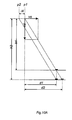
- the accuracy of the calibration procedure may be increased by increasing the number of dots used to print the lines of the calibration test pattern.
- 4 printed dots are used to define a line but this amount may be altered as required.
- Increasing the number of dots in a printed line may increases the amount of data that can be used in the statistics for calculating the center of gravity of the printed line.
- a number of algorithms are available to calculate the center of gravity of a line of adjacent printed dots, such as the algorithms used in image quality analysis products commercially available from QEA or ImageXpert.
- One example may be based on the calculation of the center of mass of each of the individual dots, fitting a straight line through these centers and using the center of this line to represent the center of gravity of the printed line in the calibration test pattern.
- the accuracy of the calibration procedure also depends on the quality of the printed dots (shape, size, density). Highly ink absorbing receiver media will reduce the density of the printed dots and reduce contrast, making it more difficult for the image analysis system to define the dot circumference and the center of mass. When the receiver medium shows a significant and uncontrolled dot spread, the calculated center of mass of the printed dots will not necessarily coincide with the landing position of the drop on the receiver medium.
- the calibration procedure may therefore benefit from using a curable ink for printing the calibration test pattern.
- the curable ink is instantly (and at least partially) cured after landing on the receiver medium so as to fix the location of the printed dots on the receiver medium. Often this will also keep the colorant on the surface of the receiver medium, being an advantage towards printed dot density and contrast.
- the size of the printed dot should not be too small for the calscan camera to be able to digitally represent the printed dot, i.e. dot size and camera resolution should be matched.
- the calscan camera system may be extended with suitable color filters and/or switchable RGB LED illumination.
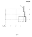
- Calibration of printing medium (see next paragraph) and throw-distance may be performed at regular positions across the printable area of the printing medium.
- the calibration test pattern may therefore include several patches, at regular positions across the printable area, that can be used to calculate positional or regional calibration correction values (see also figure 11 ).
- the patches may be identical or include position specific information.
- the calscan module has been used to grab image frames from the printed calibration test pattern, the purpose of the image frames being gathering positional information of printed dots on the printing medium and using this information for the alignment of the array of printing elements.
- the calscan module may also be used to gather information on print quality parameters like dot size and dot shape, and use this information for the calibration of the printing process.
- the additional information may for example be used to determine the optimal print resolution for a given drop volume and given wetting properties (form factor) of the printing medium, or it may be used to determine the optimal drop volume for a given print resolution and given wetting properties (form factor) of the printing medium.
- a print head where a drop volume of the ejected drops is adjustable, such as the Omnidot 760 available from Xaar plc (UK).
- Other parameters that may be relevant in this discussion are printing medium pretreatment, ink type, ink drying settings (e.g. time between drop landing and UV-curing of the drop), etc.
- the printing medium is held fixed during the printing and the print head shuttle can move in a fast scan and slow scan direction to cover the whole of the printable area.
- the invention may however also be used with other swath printer configurations, e.g. configurations where the slow scan movement of the print head shuttle relative to the printing medium is implemented by moving the printing medium relative to a fixed print head shuttle location in the slow scan direction.
- other types of printing media and transport systems may be used such as in web printing.
- the calscan module is mounted on the print head shuttle. This avoids an additional linear motion drive system for moving the calscan module in the fast scan direction.
- this may not be the preferred setup and the calscan module may be operated in x and y direction completely independent from the print head shuttle drive controls.
Claims (8)
- Un procédé pour l'alignement de l'impression de points générés par au moins une matrice d'éléments d'impression d'une imprimante à jet d'encre comprenant un système d'impression à jet d'encre selon la revendication 5, ledit procédé comprenant les étapes ci-après :- l'impression d'un motif de test d'étalonnage (80) sur un support d'impression (3),- le balayage du motif de test d'étalonnage imprimé (80),- la détermination d'au moins une valeur d'étalonnage à partir du motif de test d'étalonnage balayé (80) et- le réglage de l'alignement de ladite au moins une matrice d'éléments d'impression (52) à l'aide d'un moyen de contrôle de réglage d'alignement (22, 32),ledit procédé étant caractérisé en ce que :l'étape de l'adaptation de l'alignement de ladite au moins une matrice d'éléments d'impression (52) comprend en outre les étapes ci-après :- le déplacement d'un outil de réglage d'alignement (61), par rapport à ladite au moins une matrice d'éléments d'impression (52), à une position où l'outil de réglage d'alignement (61) peut être inséré dans le moyen de contrôle de réglage d'alignement (22, 32), et- le réglage de l'alignement de ladite au moins une matrice d'éléments d'impression (52), consistant à utiliser l'outil de réglage d'alignement (61) sur le moyen de contrôle de réglage d'alignement (22, 32) conformément à la valeur d'étalonnage.
- Procédé selon la revendication 1, caractérisé en ce que lors de l'étape du déplacement de l'outil de réglage d'alignement (61) par rapport à ladite au moins une matrice d'éléments d'impression (52), l'outil de réglage d'alignement (61) est déplacé dans un sens de balayage lent (SS) et ladite au moins une matrice d'éléments d'impression (52) est déplacée dans un sens de balayage rapide (FS).
- Procédé selon la revendication 2, caractérisé en ce que lors de l'étape du déplacement de l'outil de réglage d'alignement (61), l'outil de réglage d'alignement (61) est déplacé dans un sens perpendiculaire au sens de balayage rapide et au sens de balayage lent de façon à ce que l'outil de réglage d'alignement (61) puisse être utilisé sur le moyen de contrôle de réglage d'alignement (22, 32).
- Procédé selon l'une quelconque des revendications précédentes,
caractérisé en ce que l'outil de réglage d'alignement (61) est un tournevis automatique. - Un système d'impression à jet d'encre (1) comprenant les éléments ci-après :- une matrice d'éléments d'impression (52) permettant d'imprimer un motif de test d'étalonnage (80) sur un matériau récepteur (3),- un dispositif (90) servant au balayage du motif de test d'étalonnage imprimé (80),- un dispositif servant au calcul d'une valeur d'étalonnage à partir du motif de test d'étalonnage balayé (80) et- un outil de réglage d'alignement (61) permettant d'effectuer le réglage de l'alignement de la matrice d'éléments d'impression (52) à l'aide d'un moyen de contrôle de réglage d'alignement,caractérisé en ce que le système d'impression à jet d'encre (1) comprend en outre les éléments ci-après :- un système servant au déplacement de l'outil de réglage d'alignement (61), par rapport à la matrice d'éléments d'impression (52), à une position où l'outil de réglage d'alignement (61) peut être inséré dans le moyen de contrôle de réglage d'alignement, et- un moyen d'actionnement (62) permettant d'effectuer le réglage de l'alignement de la matrice d'éléments d'impression (52) à partir de la valeur d'étalonnage.
- Système d'impression à jet d'encre selon la revendication 5,
caractérisé en ce que le système assurant le déplacement de l'outil de réglage d'alignement (61) comprend un système d'entraînement transversal (71, 72, 73, 74) permettant le déplacement de l'outil de réglage d'alignement (61), par rapport à ladite au moins une matrice d'éléments d'impression (52), dans un sens de balayage lent (SS), un système d'entraînement du chariot de têtes d'impression permettant le déplacement de ladite au moins une matrice d'éléments d'impression (52), par rapport à l'outil de réglage d'alignement (61), dans un sens de balayage rapide (FS) et un système d'entraînement de levage (65) permettant le déplacement de l'outil de réglage d'alignement (61) dans un sens perpendiculaire au sens de balayage rapide et au sens de balayage lent. - Système d'impression à jet d'encre selon la revendication 6,
caractérisé en ce que l'axe (59) de l'outil de réglage d'alignement (61) est monté de façon mobile sur le système d'entraînement de levage (65) de façon à ce que, lors du réglage de l'alignement de ladite au moins une matrice d'éléments d'impression (52), l'outil de réglage d'alignement (61) puisse être déplacé jusque dans le moyen de contrôle de réglage d'alignement (22, 32) pour y être maintenu. - Système d'impression à jet d'encre selon l'une quelconque des revendications 5 à 7, caractérisé en ce que l'outil de réglage d'alignement (61) comprend un tournevis automatique.
Priority Applications (8)
| Application Number | Priority Date | Filing Date | Title |
|---|---|---|---|
| AT05108660T ATE439985T1 (de) | 2005-09-20 | 2005-09-20 | Apparat und verfahren zum automatischen ausrichten von druckelementreihe |
| EP05108660A EP1764226B1 (fr) | 2005-09-20 | 2005-09-20 | Dispostif et méthode d'alignement automatique de rangés d'éléments d'impression |
| DE602005016115T DE602005016115D1 (de) | 2005-09-20 | 2005-09-20 | Apparat und Verfahren zum automatischen Ausrichten von Druckelementreihe |
| ES05108660T ES2329806T3 (es) | 2005-09-20 | 2005-09-20 | Metodo y aparato para la alineacion automatica de conjuntos de elementos de impresion. |
| DK05108660T DK1764226T3 (da) | 2005-09-20 | 2005-09-20 | Fremgangsmåde og indretning til automatisk at stille arrays af printelementer på linie |
| CN2006800345725A CN101267948B (zh) | 2005-09-20 | 2006-09-19 | 用于使打印元件阵列自动对准的方法和装置 |
| US12/067,401 US8118385B2 (en) | 2005-09-20 | 2006-09-19 | Method and apparatus for automatically aligning arrays of printing elements |
| PCT/EP2006/066484 WO2007039445A1 (fr) | 2005-09-20 | 2006-09-19 | Procede et appareil pour aligner automatiquement des reseaux d'elements d'impression |
Applications Claiming Priority (1)
| Application Number | Priority Date | Filing Date | Title |
|---|---|---|---|
| EP05108660A EP1764226B1 (fr) | 2005-09-20 | 2005-09-20 | Dispostif et méthode d'alignement automatique de rangés d'éléments d'impression |
Publications (2)
| Publication Number | Publication Date |
|---|---|
| EP1764226A1 EP1764226A1 (fr) | 2007-03-21 |
| EP1764226B1 true EP1764226B1 (fr) | 2009-08-19 |
Family
ID=35735221
Family Applications (1)
| Application Number | Title | Priority Date | Filing Date |
|---|---|---|---|
| EP05108660A Active EP1764226B1 (fr) | 2005-09-20 | 2005-09-20 | Dispostif et méthode d'alignement automatique de rangés d'éléments d'impression |
Country Status (8)
| Country | Link |
|---|---|
| US (1) | US8118385B2 (fr) |
| EP (1) | EP1764226B1 (fr) |
| CN (1) | CN101267948B (fr) |
| AT (1) | ATE439985T1 (fr) |
| DE (1) | DE602005016115D1 (fr) |
| DK (1) | DK1764226T3 (fr) |
| ES (1) | ES2329806T3 (fr) |
| WO (1) | WO2007039445A1 (fr) |
Families Citing this family (30)
| Publication number | Priority date | Publication date | Assignee | Title |
|---|---|---|---|---|
| US8246138B2 (en) | 2007-07-06 | 2012-08-21 | Hewlett-Packard Development Company, L.P. | Print emulation of test pattern |
| US20090180162A1 (en) * | 2008-01-16 | 2009-07-16 | Cornell David J | Live preview scanning system and method |
| JP2010042616A (ja) * | 2008-08-13 | 2010-02-25 | Seiko Epson Corp | 調整方法 |
| US8132885B2 (en) | 2009-03-10 | 2012-03-13 | Xerox Corporation | System and method for evaluating and correcting image quality in an image generating device |
| US8300266B2 (en) * | 2009-03-12 | 2012-10-30 | Xerox Corporation | System and method for adjusting operation of printheads in an ink printing device |
| US8430471B2 (en) | 2011-07-14 | 2013-04-30 | Hewlett-Packard Development Company, L.P. | Printing head alignment adjustment |
| US8851601B2 (en) | 2012-02-07 | 2014-10-07 | Xerox Corporation | System and method for compensating for drift in multiple printheads in an inkjet printer |
| WO2014005608A1 (fr) * | 2012-07-06 | 2014-01-09 | Hewlett-Packard Development Company, L.P. | Imprimante à jet d'encre |
| US8960839B1 (en) | 2014-05-14 | 2015-02-24 | Xerox Corporation | System and method for spatial dependent correction for images printed with multiple drop parameters |
| EP3031610A1 (fr) * | 2014-12-08 | 2016-06-15 | Agfa Graphics Nv | Procédé d'étalonnage fiable pour des systèmes à jet d'encre industrielle |
| WO2017011004A1 (fr) | 2015-07-15 | 2017-01-19 | Hewlett-Packard Development Company, L.P. | Étalonnage d'imprimante |
| US10477049B2 (en) | 2015-08-31 | 2019-11-12 | Hewlett-Packard Development Company, L.P. | Media expansion compensated print content |
| JP2017053805A (ja) * | 2015-09-11 | 2017-03-16 | セイコーエプソン株式会社 | 測色装置、及び印刷装置 |
| US10440195B2 (en) | 2015-10-30 | 2019-10-08 | Hewlett-Packard Development Company, L.P. | Calibrating a media advance system of a page wide array printing device |
| DE102016014944A1 (de) | 2016-12-14 | 2018-06-14 | Dürr Systems Ag | Beschichtungsverfahren und entsprechende Beschichtungseinrichtung |
| DE102016014946A1 (de) | 2016-12-14 | 2018-06-14 | Dürr Systems Ag | Druckkopf zur Applikation eines Beschichtungsmittels auf ein Bauteil |
| DE102016014952A1 (de) | 2016-12-14 | 2018-06-14 | Dürr Systems Ag | Beschichtungseinrichtung zur Beschichtung von Bauteilen |
| DE102016014948A1 (de) | 2016-12-14 | 2018-06-14 | Dürr Systems Ag | Druckkopf und zugehöriges Betriebsverfahren |
| DE102016014953A1 (de) | 2016-12-14 | 2018-06-14 | Dürr Systems Ag | Lackieranlage und entsprechendes Lackierverfahren |
| DE102016014956A1 (de) | 2016-12-14 | 2018-06-14 | Dürr Systems Ag | Beschichtungseinrichtung und zugehöriges Betriebsverfahren |
| DE102016014920A1 (de) | 2016-12-14 | 2018-06-14 | Dürr Systems Ag | Druckkopf mit Verschiebe- und/oder Drehmechanik für zumindest eine Düsenreihe |
| DE102016014919A1 (de) | 2016-12-14 | 2018-06-14 | Dürr Systems Ag | Applikationsvorrichtung und Verfahren zum Applizieren eines Beschichtungsmittels |
| DE102016014955A1 (de) | 2016-12-14 | 2018-06-14 | Dürr Systems Ag | Beschichtungseinrichtung und entsprechendes Beschichtungsverfahren |
| DE102016014947A1 (de) | 2016-12-14 | 2018-06-14 | Dürr Systems Ag | Druckkopf zur Applikation eines Beschichtungsmittels |
| DE102016014951A1 (de) | 2016-12-14 | 2018-06-14 | Dürr Systems Ag | Beschichtungseinrichtung und zugehöriges Betriebsverfahren |
| DE102016014943A1 (de) | 2016-12-14 | 2018-06-14 | Dürr Systems Ag | Druckkopf mit Temperiereinrichtung |
| US10279585B2 (en) * | 2017-01-31 | 2019-05-07 | Xerox Corporation | Method and system for aligning ejectors that eject clear materials in a printer |
| EP3441872B1 (fr) * | 2017-08-09 | 2023-02-22 | Canon Production Printing Holding B.V. | Imprimante alimentée par rouleau, support logiciel et procédé de commande d'une imprimante alimentée par rouleau |
| WO2022203691A1 (fr) * | 2021-03-26 | 2022-09-29 | Hewlett-Packard Development Company, L.P. | Étalonnage de l'alignement d'une imprimante |
| CN113320301B (zh) * | 2021-04-26 | 2022-04-15 | 北京中电元德科技有限责任公司 | 一种打印机喷头运动调整装置 |
Family Cites Families (17)
| Publication number | Priority date | Publication date | Assignee | Title |
|---|---|---|---|---|
| US4575729A (en) * | 1984-06-28 | 1986-03-11 | The Mead Corporation | Ink printer pivotal frame |
| US4878063A (en) * | 1988-12-05 | 1989-10-31 | Eastman Kodak Company | Multicolor printing apparatus and method having vernier detection/correction system for adjusting color separation planes |
| US5146242A (en) * | 1991-03-15 | 1992-09-08 | Eastman Kodak Company | Writing beam angular alignment device |
| US5289208A (en) * | 1991-10-31 | 1994-02-22 | Hewlett-Packard Company | Automatic print cartridge alignment sensor system |
| US6102509A (en) * | 1996-05-30 | 2000-08-15 | Hewlett-Packard Company | Adaptive method for handling inkjet printing media |
| US5838338A (en) * | 1996-05-30 | 1998-11-17 | Hewlett-Packard Company | Adaptive media handling system for printing mechanisms |
| US5745308A (en) * | 1996-07-30 | 1998-04-28 | Bayer Corporation | Methods and apparatus for an optical illuminator assembly and its alignment |
| DE19755874C1 (de) * | 1997-12-04 | 1999-07-15 | Francotyp Postalia Gmbh | Verfahren zum Toleranzausgleich bei einem aus mehreren Modulen nach dem Non-Interlaced-Prinzip zusammengesetzten Tintendruckkopf |
| US6290319B1 (en) * | 1999-02-19 | 2001-09-18 | Hewlett-Packard Company | Controlling residual fine errors of dot placement in an incremental printer |
| US6232999B1 (en) * | 1999-06-25 | 2001-05-15 | Eastman Kodak Company | Method for changing focus and angle of a multichannel printhead |
| US6663222B2 (en) * | 2000-12-22 | 2003-12-16 | Agfa-Gevaert | Ink jet printer with nozzle arrays that are moveable with respect to each other |
| US6554398B2 (en) * | 2001-03-08 | 2003-04-29 | Agfa-Gevaert | Ink-jet printer equipped for aligning the printheads |
| EP1308288B1 (fr) * | 2001-11-06 | 2006-03-01 | Canon Kabushiki Kaisha | Appareil d'enregistrement à jet d'encre et procédé de correction d'un image |
| JP4401714B2 (ja) * | 2003-09-04 | 2010-01-20 | キヤノン株式会社 | 記録装置 |
| EP1674279A1 (fr) | 2004-12-22 | 2006-06-28 | Agfa-Gevaert | Système de positionnement |
| EP1764224A1 (fr) | 2005-09-20 | 2007-03-21 | Agfa Graphics N.V. | Méthode et appareil pour l'impression numérique en maintenant l'alignement de points imprimés sous de conditions d'impression variées |
| WO2007039444A1 (fr) | 2005-09-20 | 2007-04-12 | Agfa Graphics Nv | Procede et appareil pour aligner automatiquement des reseaux d'elements d'impression |
-
2005
- 2005-09-20 AT AT05108660T patent/ATE439985T1/de not_active IP Right Cessation
- 2005-09-20 DK DK05108660T patent/DK1764226T3/da active
- 2005-09-20 DE DE602005016115T patent/DE602005016115D1/de active Active
- 2005-09-20 ES ES05108660T patent/ES2329806T3/es active Active
- 2005-09-20 EP EP05108660A patent/EP1764226B1/fr active Active
-
2006
- 2006-09-19 CN CN2006800345725A patent/CN101267948B/zh active Active
- 2006-09-19 US US12/067,401 patent/US8118385B2/en active Active
- 2006-09-19 WO PCT/EP2006/066484 patent/WO2007039445A1/fr active Application Filing
Also Published As
| Publication number | Publication date |
|---|---|
| DK1764226T3 (da) | 2009-10-12 |
| CN101267948B (zh) | 2011-08-03 |
| ES2329806T3 (es) | 2009-12-01 |
| ATE439985T1 (de) | 2009-09-15 |
| EP1764226A1 (fr) | 2007-03-21 |
| DE602005016115D1 (de) | 2009-10-01 |
| US20090027433A1 (en) | 2009-01-29 |
| US8118385B2 (en) | 2012-02-21 |
| CN101267948A (zh) | 2008-09-17 |
| WO2007039445A1 (fr) | 2007-04-12 |
Similar Documents
| Publication | Publication Date | Title |
|---|---|---|
| EP1764226B1 (fr) | Dispostif et méthode d'alignement automatique de rangés d'éléments d'impression | |
| EP1764996A1 (fr) | Procédé et appareil pour l'alignement automatique de matrices d'éléments d'impression | |
| EP1764224A1 (fr) | Méthode et appareil pour l'impression numérique en maintenant l'alignement de points imprimés sous de conditions d'impression variées | |
| US7073883B2 (en) | Method of aligning inkjet nozzle banks for an inkjet printer | |
| JP5063327B2 (ja) | インクジェット記録装置および調整値取得方法 | |
| US7445302B2 (en) | Method for determining a printhead gap in an ink jet apparatus that performs bi-directional alignment of the printhead | |
| US20120113184A1 (en) | Method and system for detecting print head roll | |
| WO2007039444A1 (fr) | Procede et appareil pour aligner automatiquement des reseaux d'elements d'impression | |
| JPH0825703A (ja) | 移動可能なプリントヘッドを有するプリンタ | |
| EP3401109B1 (fr) | Imprimante et procédé de commande d'une imprimante | |
| CN105856886A (zh) | 扫描式喷墨打印方法及喷墨打印装置 | |
| EP1721753B1 (fr) | Plateau de transport segmente pour un support d'enregistrement et calibrage de la distance d'éjection dans une imprimante numérique | |
| US9186886B2 (en) | Method of forming ink ejection adjustment pattern, ink ejection adjustment method for inkjet head and inkjet printer | |
| US9120342B2 (en) | Method for full bleed printing | |
| EP1238813A1 (fr) | Imprimante jet d'encre équipée pour aligner les têtes d'impression | |
| US6984082B2 (en) | Printer, method for determining top edge of object to be printed, method for determining bottom edge of object to be printed, computer program, and computer system | |
| US7708362B2 (en) | Printhead error compensation | |
| JP6040241B2 (ja) | 連続するスワスを印刷する方法 | |
| JP2004276394A (ja) | 印刷装置およびその印刷ヘッドの取り付け方法 | |
| US6938975B2 (en) | Method of reducing printing defects in an ink jet printer | |
| EP1518695B1 (fr) | Méthode et système pour détecter la rotation de tête d'impression en utilisant des photosenseurs | |
| US10962915B2 (en) | Image printing apparatus, reading apparatus, image printing method, and printing medium conveyance method | |
| JP2002103724A (ja) | プリンタ |
Legal Events
| Date | Code | Title | Description |
|---|---|---|---|
| PUAI | Public reference made under article 153(3) epc to a published international application that has entered the european phase |
Free format text: ORIGINAL CODE: 0009012 |
|
| AK | Designated contracting states |
Kind code of ref document: A1 Designated state(s): AT BE BG CH CY CZ DE DK EE ES FI FR GB GR HU IE IS IT LI LT LU LV MC NL PL PT RO SE SI SK TR |
|
| AX | Request for extension of the european patent |
Extension state: AL BA HR MK YU |
|
| 17P | Request for examination filed |
Effective date: 20070921 |
|
| 17Q | First examination report despatched |
Effective date: 20071029 |
|
| AKX | Designation fees paid |
Designated state(s): AT BE BG CH CY CZ DE DK EE ES FI FR GB GR HU IE IS IT LI LT LU LV MC NL PL PT RO SE SI SK TR |
|
| GRAP | Despatch of communication of intention to grant a patent |
Free format text: ORIGINAL CODE: EPIDOSNIGR1 |
|
| GRAS | Grant fee paid |
Free format text: ORIGINAL CODE: EPIDOSNIGR3 |
|
| GRAA | (expected) grant |
Free format text: ORIGINAL CODE: 0009210 |
|
| AK | Designated contracting states |
Kind code of ref document: B1 Designated state(s): AT BE BG CH CY CZ DE DK EE ES FI FR GB GR HU IE IS IT LI LT LU LV MC NL PL PT RO SE SI SK TR |
|
| REG | Reference to a national code |
Ref country code: GB Ref legal event code: FG4D |
|
| REG | Reference to a national code |
Ref country code: CH Ref legal event code: EP |
|
| REG | Reference to a national code |
Ref country code: IE Ref legal event code: FG4D |
|
| REF | Corresponds to: |
Ref document number: 602005016115 Country of ref document: DE Date of ref document: 20091001 Kind code of ref document: P |
|
| REG | Reference to a national code |
Ref country code: SE Ref legal event code: TRGR |
|
| REG | Reference to a national code |
Ref country code: DK Ref legal event code: T3 |
|
| REG | Reference to a national code |
Ref country code: ES Ref legal event code: FG2A Ref document number: 2329806 Country of ref document: ES Kind code of ref document: T3 |
|
| LTIE | Lt: invalidation of european patent or patent extension |
Effective date: 20090819 |
|
| PG25 | Lapsed in a contracting state [announced via postgrant information from national office to epo] |
Ref country code: FI Free format text: LAPSE BECAUSE OF FAILURE TO SUBMIT A TRANSLATION OF THE DESCRIPTION OR TO PAY THE FEE WITHIN THE PRESCRIBED TIME-LIMIT Effective date: 20090819 Ref country code: AT Free format text: LAPSE BECAUSE OF FAILURE TO SUBMIT A TRANSLATION OF THE DESCRIPTION OR TO PAY THE FEE WITHIN THE PRESCRIBED TIME-LIMIT Effective date: 20090819 Ref country code: LT Free format text: LAPSE BECAUSE OF FAILURE TO SUBMIT A TRANSLATION OF THE DESCRIPTION OR TO PAY THE FEE WITHIN THE PRESCRIBED TIME-LIMIT Effective date: 20090819 Ref country code: IS Free format text: LAPSE BECAUSE OF FAILURE TO SUBMIT A TRANSLATION OF THE DESCRIPTION OR TO PAY THE FEE WITHIN THE PRESCRIBED TIME-LIMIT Effective date: 20091219 |
|
| PG25 | Lapsed in a contracting state [announced via postgrant information from national office to epo] |
Ref country code: PL Free format text: LAPSE BECAUSE OF FAILURE TO SUBMIT A TRANSLATION OF THE DESCRIPTION OR TO PAY THE FEE WITHIN THE PRESCRIBED TIME-LIMIT Effective date: 20090819 Ref country code: SI Free format text: LAPSE BECAUSE OF FAILURE TO SUBMIT A TRANSLATION OF THE DESCRIPTION OR TO PAY THE FEE WITHIN THE PRESCRIBED TIME-LIMIT Effective date: 20090819 Ref country code: LV Free format text: LAPSE BECAUSE OF FAILURE TO SUBMIT A TRANSLATION OF THE DESCRIPTION OR TO PAY THE FEE WITHIN THE PRESCRIBED TIME-LIMIT Effective date: 20090819 |
|
| PG25 | Lapsed in a contracting state [announced via postgrant information from national office to epo] |
Ref country code: CY Free format text: LAPSE BECAUSE OF FAILURE TO SUBMIT A TRANSLATION OF THE DESCRIPTION OR TO PAY THE FEE WITHIN THE PRESCRIBED TIME-LIMIT Effective date: 20090819 Ref country code: PT Free format text: LAPSE BECAUSE OF FAILURE TO SUBMIT A TRANSLATION OF THE DESCRIPTION OR TO PAY THE FEE WITHIN THE PRESCRIBED TIME-LIMIT Effective date: 20091221 Ref country code: BG Free format text: LAPSE BECAUSE OF FAILURE TO SUBMIT A TRANSLATION OF THE DESCRIPTION OR TO PAY THE FEE WITHIN THE PRESCRIBED TIME-LIMIT Effective date: 20091119 |
|
| PG25 | Lapsed in a contracting state [announced via postgrant information from national office to epo] |
Ref country code: MC Free format text: LAPSE BECAUSE OF NON-PAYMENT OF DUE FEES Effective date: 20090930 Ref country code: RO Free format text: LAPSE BECAUSE OF FAILURE TO SUBMIT A TRANSLATION OF THE DESCRIPTION OR TO PAY THE FEE WITHIN THE PRESCRIBED TIME-LIMIT Effective date: 20090819 Ref country code: EE Free format text: LAPSE BECAUSE OF FAILURE TO SUBMIT A TRANSLATION OF THE DESCRIPTION OR TO PAY THE FEE WITHIN THE PRESCRIBED TIME-LIMIT Effective date: 20090819 Ref country code: CZ Free format text: LAPSE BECAUSE OF FAILURE TO SUBMIT A TRANSLATION OF THE DESCRIPTION OR TO PAY THE FEE WITHIN THE PRESCRIBED TIME-LIMIT Effective date: 20090819 |
|
| REG | Reference to a national code |
Ref country code: CH Ref legal event code: PL |
|
| PG25 | Lapsed in a contracting state [announced via postgrant information from national office to epo] |
Ref country code: SK Free format text: LAPSE BECAUSE OF FAILURE TO SUBMIT A TRANSLATION OF THE DESCRIPTION OR TO PAY THE FEE WITHIN THE PRESCRIBED TIME-LIMIT Effective date: 20090819 |
|
| PLBE | No opposition filed within time limit |
Free format text: ORIGINAL CODE: 0009261 |
|
| STAA | Information on the status of an ep patent application or granted ep patent |
Free format text: STATUS: NO OPPOSITION FILED WITHIN TIME LIMIT |
|
| 26N | No opposition filed |
Effective date: 20100520 |
|
| PG25 | Lapsed in a contracting state [announced via postgrant information from national office to epo] |
Ref country code: IE Free format text: LAPSE BECAUSE OF NON-PAYMENT OF DUE FEES Effective date: 20090920 |
|
| PG25 | Lapsed in a contracting state [announced via postgrant information from national office to epo] |
Ref country code: GR Free format text: LAPSE BECAUSE OF FAILURE TO SUBMIT A TRANSLATION OF THE DESCRIPTION OR TO PAY THE FEE WITHIN THE PRESCRIBED TIME-LIMIT Effective date: 20091120 Ref country code: CH Free format text: LAPSE BECAUSE OF NON-PAYMENT OF DUE FEES Effective date: 20090930 Ref country code: LI Free format text: LAPSE BECAUSE OF NON-PAYMENT OF DUE FEES Effective date: 20090930 |
|
| PG25 | Lapsed in a contracting state [announced via postgrant information from national office to epo] |
Ref country code: LU Free format text: LAPSE BECAUSE OF NON-PAYMENT OF DUE FEES Effective date: 20090920 |
|
| PG25 | Lapsed in a contracting state [announced via postgrant information from national office to epo] |
Ref country code: HU Free format text: LAPSE BECAUSE OF FAILURE TO SUBMIT A TRANSLATION OF THE DESCRIPTION OR TO PAY THE FEE WITHIN THE PRESCRIBED TIME-LIMIT Effective date: 20100220 |
|
| PG25 | Lapsed in a contracting state [announced via postgrant information from national office to epo] |
Ref country code: TR Free format text: LAPSE BECAUSE OF FAILURE TO SUBMIT A TRANSLATION OF THE DESCRIPTION OR TO PAY THE FEE WITHIN THE PRESCRIBED TIME-LIMIT Effective date: 20090819 |
|
| REG | Reference to a national code |
Ref country code: FR Ref legal event code: PLFP Year of fee payment: 12 |
|
| PGFP | Annual fee paid to national office [announced via postgrant information from national office to epo] |
Ref country code: NL Payment date: 20160801 Year of fee payment: 12 |
|
| PGFP | Annual fee paid to national office [announced via postgrant information from national office to epo] |
Ref country code: DK Payment date: 20160923 Year of fee payment: 12 |
|
| PGFP | Annual fee paid to national office [announced via postgrant information from national office to epo] |
Ref country code: SE Payment date: 20160926 Year of fee payment: 12 |
|
| PGFP | Annual fee paid to national office [announced via postgrant information from national office to epo] |
Ref country code: BE Payment date: 20160727 Year of fee payment: 12 Ref country code: ES Payment date: 20160923 Year of fee payment: 12 |
|
| REG | Reference to a national code |
Ref country code: FR Ref legal event code: PLFP Year of fee payment: 13 |
|
| REG | Reference to a national code |
Ref country code: DE Ref legal event code: R081 Ref document number: 602005016115 Country of ref document: DE Owner name: AGFA NV, BE Free format text: FORMER OWNER: AGFA GRAPHICS N.V., MORTSEL, BE |
|
| REG | Reference to a national code |
Ref country code: DK Ref legal event code: EBP Effective date: 20170930 |
|
| REG | Reference to a national code |
Ref country code: SE Ref legal event code: EUG |
|
| REG | Reference to a national code |
Ref country code: NL Ref legal event code: MM Effective date: 20171001 |
|
| REG | Reference to a national code |
Ref country code: BE Ref legal event code: MM Effective date: 20170930 |
|
| PG25 | Lapsed in a contracting state [announced via postgrant information from national office to epo] |
Ref country code: NL Free format text: LAPSE BECAUSE OF NON-PAYMENT OF DUE FEES Effective date: 20171001 |
|
| REG | Reference to a national code |
Ref country code: FR Ref legal event code: PLFP Year of fee payment: 14 |
|
| REG | Reference to a national code |
Ref country code: FR Ref legal event code: CD Owner name: AGFA NV, BE Effective date: 20180628 |
|
| PG25 | Lapsed in a contracting state [announced via postgrant information from national office to epo] |
Ref country code: BE Free format text: LAPSE BECAUSE OF NON-PAYMENT OF DUE FEES Effective date: 20170930 |
|
| REG | Reference to a national code |
Ref country code: ES Ref legal event code: FD2A Effective date: 20181018 |
|
| PG25 | Lapsed in a contracting state [announced via postgrant information from national office to epo] |
Ref country code: DK Free format text: LAPSE BECAUSE OF NON-PAYMENT OF DUE FEES Effective date: 20170930 |
|
| PG25 | Lapsed in a contracting state [announced via postgrant information from national office to epo] |
Ref country code: ES Free format text: LAPSE BECAUSE OF NON-PAYMENT OF DUE FEES Effective date: 20170921 |
|
| PG25 | Lapsed in a contracting state [announced via postgrant information from national office to epo] |
Ref country code: SE Free format text: LAPSE BECAUSE OF NON-PAYMENT OF DUE FEES Effective date: 20170921 |
|
| PGFP | Annual fee paid to national office [announced via postgrant information from national office to epo] |
Ref country code: IT Payment date: 20220930 Year of fee payment: 18 |
|
| PGFP | Annual fee paid to national office [announced via postgrant information from national office to epo] |
Ref country code: GB Payment date: 20230915 Year of fee payment: 19 |
|
| PGFP | Annual fee paid to national office [announced via postgrant information from national office to epo] |
Ref country code: FR Payment date: 20230915 Year of fee payment: 19 Ref country code: DE Payment date: 20230811 Year of fee payment: 19 |