EP1764158A2 - Verriegelungshülse zur Befestigung einer Verschlusseinrichtung sowie Verschlusseinrichtung - Google Patents
Verriegelungshülse zur Befestigung einer Verschlusseinrichtung sowie Verschlusseinrichtung Download PDFInfo
- Publication number
- EP1764158A2 EP1764158A2 EP06019267A EP06019267A EP1764158A2 EP 1764158 A2 EP1764158 A2 EP 1764158A2 EP 06019267 A EP06019267 A EP 06019267A EP 06019267 A EP06019267 A EP 06019267A EP 1764158 A2 EP1764158 A2 EP 1764158A2
- Authority
- EP
- European Patent Office
- Prior art keywords
- locking sleeve
- locking
- closure
- retaining
- sleeve according
- Prior art date
- Legal status (The legal status is an assumption and is not a legal conclusion. Google has not performed a legal analysis and makes no representation as to the accuracy of the status listed.)
- Granted
Links
- 238000007789 sealing Methods 0.000 claims description 25
- 239000000463 material Substances 0.000 claims description 11
- 239000002184 metal Substances 0.000 claims description 5
- 239000002304 perfume Substances 0.000 description 8
- 230000014759 maintenance of location Effects 0.000 description 4
- 230000000694 effects Effects 0.000 description 3
- 238000005304 joining Methods 0.000 description 2
- 238000004519 manufacturing process Methods 0.000 description 2
- 239000011324 bead Substances 0.000 description 1
- 238000009826 distribution Methods 0.000 description 1
- 238000004049 embossing Methods 0.000 description 1
- 238000005516 engineering process Methods 0.000 description 1
- 239000011521 glass Substances 0.000 description 1
- 239000006199 nebulizer Substances 0.000 description 1
- 230000002093 peripheral effect Effects 0.000 description 1
- 238000005096 rolling process Methods 0.000 description 1
Images

Classifications
-
- B—PERFORMING OPERATIONS; TRANSPORTING
- B65—CONVEYING; PACKING; STORING; HANDLING THIN OR FILAMENTARY MATERIAL
- B65D—CONTAINERS FOR STORAGE OR TRANSPORT OF ARTICLES OR MATERIALS, e.g. BAGS, BARRELS, BOTTLES, BOXES, CANS, CARTONS, CRATES, DRUMS, JARS, TANKS, HOPPERS, FORWARDING CONTAINERS; ACCESSORIES, CLOSURES, OR FITTINGS THEREFOR; PACKAGING ELEMENTS; PACKAGES
- B65D43/00—Lids or covers for rigid or semi-rigid containers
- B65D43/02—Removable lids or covers
- B65D43/0235—Removable lids or covers with integral tamper element
- B65D43/0264—Removable lids or covers with integral tamper element secured only by friction or gravity before removal of the tamper element
- B65D43/0274—Removable lids or covers with integral tamper element secured only by friction or gravity before removal of the tamper element only on the outside, or a part turned to the outside, of the mouth of the container
-
- B—PERFORMING OPERATIONS; TRANSPORTING
- B05—SPRAYING OR ATOMISING IN GENERAL; APPLYING FLUENT MATERIALS TO SURFACES, IN GENERAL
- B05B—SPRAYING APPARATUS; ATOMISING APPARATUS; NOZZLES
- B05B11/00—Single-unit hand-held apparatus in which flow of contents is produced by the muscular force of the operator at the moment of use
- B05B11/01—Single-unit hand-held apparatus in which flow of contents is produced by the muscular force of the operator at the moment of use characterised by the means producing the flow
- B05B11/10—Pump arrangements for transferring the contents from the container to a pump chamber by a sucking effect and forcing the contents out through the dispensing nozzle
- B05B11/1042—Components or details
- B05B11/1043—Sealing or attachment arrangements between pump and container
- B05B11/1049—Attachment arrangements comprising a deformable or resilient ferrule clamped or locked onto the neck of the container by displacing, e.g. sliding, a sleeve surrounding the ferrule
-
- B—PERFORMING OPERATIONS; TRANSPORTING
- B65—CONVEYING; PACKING; STORING; HANDLING THIN OR FILAMENTARY MATERIAL
- B65D—CONTAINERS FOR STORAGE OR TRANSPORT OF ARTICLES OR MATERIALS, e.g. BAGS, BARRELS, BOTTLES, BOXES, CANS, CARTONS, CRATES, DRUMS, JARS, TANKS, HOPPERS, FORWARDING CONTAINERS; ACCESSORIES, CLOSURES, OR FITTINGS THEREFOR; PACKAGING ELEMENTS; PACKAGES
- B65D2543/00—Lids or covers essentially for box-like containers
- B65D2543/00009—Details of lids or covers for rigid or semi-rigid containers
- B65D2543/00018—Overall construction of the lid
- B65D2543/00064—Shape of the outer periphery
- B65D2543/00074—Shape of the outer periphery curved
- B65D2543/00092—Shape of the outer periphery curved circular
-
- B—PERFORMING OPERATIONS; TRANSPORTING
- B65—CONVEYING; PACKING; STORING; HANDLING THIN OR FILAMENTARY MATERIAL
- B65D—CONTAINERS FOR STORAGE OR TRANSPORT OF ARTICLES OR MATERIALS, e.g. BAGS, BARRELS, BOTTLES, BOXES, CANS, CARTONS, CRATES, DRUMS, JARS, TANKS, HOPPERS, FORWARDING CONTAINERS; ACCESSORIES, CLOSURES, OR FITTINGS THEREFOR; PACKAGING ELEMENTS; PACKAGES
- B65D2543/00—Lids or covers essentially for box-like containers
- B65D2543/00009—Details of lids or covers for rigid or semi-rigid containers
- B65D2543/00018—Overall construction of the lid
- B65D2543/00259—Materials used
- B65D2543/00296—Plastic
-
- B—PERFORMING OPERATIONS; TRANSPORTING
- B65—CONVEYING; PACKING; STORING; HANDLING THIN OR FILAMENTARY MATERIAL
- B65D—CONTAINERS FOR STORAGE OR TRANSPORT OF ARTICLES OR MATERIALS, e.g. BAGS, BARRELS, BOTTLES, BOXES, CANS, CARTONS, CRATES, DRUMS, JARS, TANKS, HOPPERS, FORWARDING CONTAINERS; ACCESSORIES, CLOSURES, OR FITTINGS THEREFOR; PACKAGING ELEMENTS; PACKAGES
- B65D2543/00—Lids or covers essentially for box-like containers
- B65D2543/00009—Details of lids or covers for rigid or semi-rigid containers
- B65D2543/00444—Contact between the container and the lid
- B65D2543/00481—Contact between the container and the lid on the inside or the outside of the container
- B65D2543/0049—Contact between the container and the lid on the inside or the outside of the container on the inside, or a part turned to the inside of the mouth of the container
- B65D2543/00527—NO contact
-
- B—PERFORMING OPERATIONS; TRANSPORTING
- B65—CONVEYING; PACKING; STORING; HANDLING THIN OR FILAMENTARY MATERIAL
- B65D—CONTAINERS FOR STORAGE OR TRANSPORT OF ARTICLES OR MATERIALS, e.g. BAGS, BARRELS, BOTTLES, BOXES, CANS, CARTONS, CRATES, DRUMS, JARS, TANKS, HOPPERS, FORWARDING CONTAINERS; ACCESSORIES, CLOSURES, OR FITTINGS THEREFOR; PACKAGING ELEMENTS; PACKAGES
- B65D2543/00—Lids or covers essentially for box-like containers
- B65D2543/00009—Details of lids or covers for rigid or semi-rigid containers
- B65D2543/00444—Contact between the container and the lid
- B65D2543/00481—Contact between the container and the lid on the inside or the outside of the container
- B65D2543/00537—Contact between the container and the lid on the inside or the outside of the container on the outside, or a part turned to the outside of the mouth of the container
-
- B—PERFORMING OPERATIONS; TRANSPORTING
- B65—CONVEYING; PACKING; STORING; HANDLING THIN OR FILAMENTARY MATERIAL
- B65D—CONTAINERS FOR STORAGE OR TRANSPORT OF ARTICLES OR MATERIALS, e.g. BAGS, BARRELS, BOTTLES, BOXES, CANS, CARTONS, CRATES, DRUMS, JARS, TANKS, HOPPERS, FORWARDING CONTAINERS; ACCESSORIES, CLOSURES, OR FITTINGS THEREFOR; PACKAGING ELEMENTS; PACKAGES
- B65D2543/00—Lids or covers essentially for box-like containers
- B65D2543/00009—Details of lids or covers for rigid or semi-rigid containers
- B65D2543/00444—Contact between the container and the lid
- B65D2543/00574—Contact between the container and the lid secured locally, i.e. a lot less than half the periphery
-
- B—PERFORMING OPERATIONS; TRANSPORTING
- B65—CONVEYING; PACKING; STORING; HANDLING THIN OR FILAMENTARY MATERIAL
- B65D—CONTAINERS FOR STORAGE OR TRANSPORT OF ARTICLES OR MATERIALS, e.g. BAGS, BARRELS, BOTTLES, BOXES, CANS, CARTONS, CRATES, DRUMS, JARS, TANKS, HOPPERS, FORWARDING CONTAINERS; ACCESSORIES, CLOSURES, OR FITTINGS THEREFOR; PACKAGING ELEMENTS; PACKAGES
- B65D2543/00—Lids or covers essentially for box-like containers
- B65D2543/00009—Details of lids or covers for rigid or semi-rigid containers
- B65D2543/00444—Contact between the container and the lid
- B65D2543/00592—Snapping means
- B65D2543/00712—Snapping means on the lid
- B65D2543/00722—Profiles
- B65D2543/00731—Groove or hollow bead
-
- B—PERFORMING OPERATIONS; TRANSPORTING
- B65—CONVEYING; PACKING; STORING; HANDLING THIN OR FILAMENTARY MATERIAL
- B65D—CONTAINERS FOR STORAGE OR TRANSPORT OF ARTICLES OR MATERIALS, e.g. BAGS, BARRELS, BOTTLES, BOXES, CANS, CARTONS, CRATES, DRUMS, JARS, TANKS, HOPPERS, FORWARDING CONTAINERS; ACCESSORIES, CLOSURES, OR FITTINGS THEREFOR; PACKAGING ELEMENTS; PACKAGES
- B65D2543/00—Lids or covers essentially for box-like containers
- B65D2543/00009—Details of lids or covers for rigid or semi-rigid containers
- B65D2543/00444—Contact between the container and the lid
- B65D2543/00592—Snapping means
- B65D2543/00712—Snapping means on the lid
- B65D2543/00787—Periphery concerned
- B65D2543/00814—Dots
Definitions
- the present invention relates to a locking sleeve for fastening a closure device according to the preamble of claim 1 and a closure device for closing a container opening, comprising a sealing plug made of plastic and such a locking sleeve.
- Closure devices of the type mentioned above can basically be used wherever it comes to securing a sealing plug made of plastic in its relative positioning with respect to a sealing plug receiving part. Depending on the design of the sealing plug, this results in special applications.
- the closure plug may be used to close a bottle, the locking sleeve serving to secure the plug position in the bottle opening.
- a special field of use for the closure device results in the closure of perfume bottles, the stopper regularly is designed as an atomizer, which is arranged in the bottle opening.
- a locking sleeve is arranged coaxially on the sealing plug, which is axially displaceable with respect to this in stopper positioned in the bottle opening up to a system of a stop collar of the locking sleeve on a stop surface of the atomizer.
- the locking sleeve In its locking position, the locking sleeve is arranged with an arranged on its inner circumferential surface, annular embossing grooves retaining means in engagement with the outer surface of the locking flange of the sealing plug or the atomizing device. In this position, the locking engagement of the locking flange is secured.
- the retaining device is formed on the inside of the locking sleeve by annular recesses in the inner wall of the locking sleeve. Due to the ring-shaped retention device, although an effective retention effect against a withdrawal force separating the locking sleeve from the closure plug results. However, a rotation of the locking sleeve on the closure plug or the locking flange is readily possible, so that the user of the perfume bottle could give the impression that the atomizer is insufficiently secured to the bottle. This reduces the value of the product, ie the perfume bottle, in the eyes of the user.
- a use of the known closure device consisting of sealing plugs made of plastic and locking sleeve made of metal, in the cases not possible in which a relative rotational positioning of the parts is to be ensured against each other.
- the present invention has for its object to provide a closure device of the type mentioned, on the one hand increases the impression of valency in the consumer when using the closure device on a perfume bottle or on a similar luxury item.
- a closure device is to be proposed, which, in addition to the above, allows further applications, in particular generally in the field of fastening technology.
- the locking sleeve according to the invention has the features of claim 1 and the closure device according to the invention the features of claim 9.
- the locking sleeve according to the invention has a sleeve body, which is provided at least at its lower end with a Stülpkragen, the Stülpkragen for enveloping cover an outer surface of the closure device has an inner circumferential surface which is provided at least in a covering area with the outer surface with a retaining device ,
- the retaining devices have a plurality of retaining units, which are arranged radially distributed over the circumference of the inner circumferential surface.
- the retaining units are arranged in the axial direction one behind the other and have over a partial circumference of the lateral surface extending, linear depressions. Due to the creeping capacity of the plastic material of the sealing plug, these recesses or grooves extending in the circumferential direction ensure engagement of the plastic material in the recesses in an outer peripheral surface of a flange part of the sealing plug and the sleeve inner surface surrounding the container opening, so that both a form resistance against a removal of the locking sleeve from the sealing plug, as well as a radial rotational resistance is realized, which prevents a relative rotation of the locking sleeve relative to the sealing plug.
- the retaining units each have mutually parallel recesses which are distributed equidistantly over the circumference of the lateral surface, it is particularly easy to produce the formed on the inner circumferential surface of the locking sleeve retaining units by a rolling tool that with appropriate profiling on the inner circumferential surface the locking sleeve produces the desired depressions.
- the retaining units are designed as webs extending axially on the lateral surface and extending over a partial region of the overlapping region.
- these webs act as radial anti-rotation by the engagement of the webs in the plastic material of the sealing plug.
- a shape resistance in the direction of an axially acting pull-off force is created by the length of the webs, which is reduced compared to the overlapping area.
- the retaining units are formed by webs which each comprise at least two web units arranged axially one behind the other, separated by a recess, the webs can also extend beyond the overlap area, since the form resistance counteracting an axial peel force in this case by the two Stegechen of mutually separating recesses is created.
- the production of the locking sleeve with a regularly trained tool is possible, on the other hand enables the radially equidistant distribution of the webs simultaneously a centering effect, which facilitates the assembly of the locking sleeve and the sealing plug.
- the retaining units are formed by depressions, which are formed in a formed by folding at the bottom of the sleeve body inner collar.
- the closure device according to the invention for closing a container opening comprises a sealing plug made of plastic and a locking sleeve according to the manner described above, wherein the locking sleeve has a dimensionally stiffer material than the sealing plug.
- the closure device according to the invention can be used particularly advantageously in combination with a perfume bottle or the like if the closure stopper is designed as an atomizer device. It is advantageous, in particular to achieve a desired valence of the product, advantageous to form the locking sleeve made of metal.
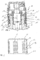
- Fig. 1 shows a closure device 10 which is arranged on a glass bottle, for example a perfume bottle.
- the closure device comprises a closure stopper 11, which is formed in the case of the present embodiment as a nebulizer device having at its upper end a locking flange 12 designed as a fastening device, which surrounds over its circumference arranged locking tabs 13 a bottle edge 14.
- the locking flange 12 and the locking tabs 13 are formed from a form-elastic plastic material and have at their free ends latching lugs 15 which in the arrangement of the locking flange 12 on the bottle opening in the manner shown in Fig. 1 behind the lower edge of the bottle edge fourteenth engage trained annular bead 16 in the manner of a snap-fit connection.
- a metal locking sleeve 17 is combined with the locking flange 12 and the stopper 11, in their deviating from the illustration in Fig. 1 mounting configuration with its lower edge 18 on a mounting shoulder 19 of the locking flange 12 is applied, as shown in Fig. 1 with dashed line.
- the locking sleeve 17 is transferred to secure the position of the Rastflansches 12 means a direction indicated in Fig. 1 joining force 20 shown in Fig. 1 in its illustrated in FIG. 1 locking position.
- the locking sleeve 17 has on its sleeve inner surface 21 formed by the inner circumferential surface a retaining device 22 which has retaining units 23 which are distributed in the radial direction over the circumference and each extend axially in the present case.
- the individual retaining units 23 are arranged in the axial direction one behind the other lying, linear depressions or grooves 24, which are shown enlarged in Fig. 3 , and extend in the circumferential direction.
- six retaining units 23 are distributed radially over the circumference and arranged equidistantly.
- FIG. 4 shows a locking sleeve 30, which has a retaining device 26 which, according to the present exemplary embodiment, has a total of twenty-four retaining units 27 distributed radially over the sleeve inner surface 21, which are each formed as axially extending rib webs.
- the retaining means or rib webs 27 also each have in the axial direction consecutively and spaced apart web notches 28, as shown in particular in Fig. 5 .
- the web notches 28 serve primarily to produce a withdrawal force acting against a withdrawal force, and the rib webs 27 prevent a relative rotation between the locking sleeve 30 and the sealing plug 11 or the locking flange 12, in particular through their engagement in the plastic material of the sealing plug 11 and the locking flange 12.
- Fig. 6 shows a locking sleeve 29 which is provided at its lower edge with a Randfalz 31 for forming an inner collar 33.
- the edge fold 31 is, as shown in particular in an enlarged partial view in FIG. 6 , provided in a thinned lower edge region of the locking sleeve 29, so that the doubled in the region of Randfalzes 31 arrangement of the sleeve wall is not twice but only one the other wall thickness of the locking sleeve exceeds by a smaller amount than the wall thickness.
- the collar 33 forms a retaining device acting in the axial direction. If, as indicated in dashed line in Fig. 6 , recesses 32 are provided in the collar 33, which are arranged distributed radially over the collar 33, beyond a retention effect in the radial direction is achieved.
Landscapes
- Engineering & Computer Science (AREA)
- Mechanical Engineering (AREA)
- Closures For Containers (AREA)
- Reduction Rolling/Reduction Stand/Operation Of Reduction Machine (AREA)
- Dowels (AREA)
Abstract
Description
- Die vorliegende Erfindung betrifft eine Verriegelungshülse zur Befestigung einer Verschlussvorrichtung gemäß dem Oberbegriff des Anspruchs 1 sowie eine Verschlussvorrichtung zum Verschluss einer Behälteröffnung, umfassend einen Verschlussstopfen aus Kunststoff und eine derartige Verriegelungshülse.
- Verschlussvorrichtungen der eingangs genannten Art können grundsätzlich überall dort eingesetzt werden, wo es darum geht, einen Verschlussstopfen aus Kunststoff in seiner Relativpositionierung gegenüber einem den Verschlussstopfen aufnehmenden Teil zu sichern. Je nach Ausbildung des Verschlussstopfens ergeben sich dabei besondere Einsatzbereiche. Beispielsweise kann der Verschlussstopfen zum Verschluss einer Flasche verwendet werden, wobei die Verriegelungshülse zur Sicherung der Verschlussstopfenposition in der Flaschenöffnung dient.
- Ein besonderer Einsatzbereich für die Verschlusseinrichtung ergibt sich beim Verschluss von Parfümflakons, wobei der Verschlussstopfen regelmäßig als Zerstäubereinrichtung ausgebildet ist, die in der Flaschenöffnung angeordnet ist.
- Aus der
US 6,253,941 B1 ist eine derartig eingesetzte Verschlusseinrichtung bekannt, mit einem als Zerstäubereinrichtung ausgebildeten Verschlussstopfen, der als Bestandteil der Zerstäubereinrichtung einen Flanschteil aufweist zur Anordnung am stirnseitigen Ende der Flaschenöffnung. Der Verschlussstopfen weist in seinem den oberen Flaschenrand umgebenden Befestigungsbereich einen Rastflansch auf, der den Flaschenrand umschließt und so die Position des Verschlussstopfens beziehungsweise der Zerstäubereinrichtung in der Flaschenöffnung definiert. Zur Verriegelung des Verschlussstopfens in der vorgenannten Position ist koaxial auf dem Verschlussstopfen eine Verriegelungshülse angeordnet, die bei in der Flaschenöffnung positioniertem Verschlussstopfen gegenüber diesem axial verschiebbar ist bis zu einer Anlage eines Anschlagbunds der Verriegelungshülse an einer Anschlagfläche der Zerstäubereinrichtung. In ihrer Verriegelungsposition befindet sich die Verriegelungshülse mit einer auf ihrer inneren Mantelfläche angeordneten, ringförmige Prägerillen aufweisenden Rückhalteeinrichtung im Eingriff mit der äußeren Mantelfläche des Rastflansches des Verschlussstopfens beziehungsweise der Zerstäubereinrichtung. In dieser Position ist der Rasteingriff des Rastflansches gesichert. Durch den Eingriff zwischen der Rückhalteeinrichtung auf der Innenfläche der metallenen Verriegelungshülse mit dem Kunststoffmaterial des Verschlussstopfens beziehungsweise des Rastflansches ist auch sicher gestellt, dass ein Abziehen der Verriegelungshülse vom Flaschenhals nur mit einer Kraft erfolgen könnte, die beim Gebrauch des Parfümflakons, also beispielsweise beim Abziehen einer auf die Verriegelungshülse aufgeschobenen Verschlusskappe, nicht auftritt. Somit ist auch wirksam verhindert, dass mit einem Abziehen der Verschlusskappe ein unbeabsichtigtes Lösen der Verriegelungshülse aus dem Eingriff mit dem Verschlussstopfen beziehungsweise der Zerstäubereinrichtung erfolgen kann, was die Funktion des Parfümflakons beziehungsweise der Zerstäubereinrichtung gefährden könnte. - Bei der bekannten Verschlusseinrichtung ist die Rückhalteeinrichtung auf der Innenseite der Verriegelungshülse durch ringförmige Vertiefungen in der Innenwandung der Verriegelungshülse gebildet. Aufgrund der ringförmig ausgebildeten Rückhalteeinrichtung ergibt sich zwar eine wirksame Rückhaltewirkung gegen ein die Verriegelungshülse vom Verschlussstopfen trennende Abzugskraft. Jedoch ist ohne Weiteres eine Rotation der Verriegelungshülse auf dem Verschlussstopfen beziehungsweise dem Rastflansch möglich, so dass beim Benutzer des Parfümflakons der Eindruck entstehen könnte, dass die Zerstäubereinrichtung unzureichend am Flakon gesichert ist. Hierdurch wird die Wertigkeit des Produkts, also des Parfümflakons, in den Augen des Benutzers reduziert. Darüber hinaus ist grundsätzlich eine Verwendung der bekannten Verschlusseinrichtung, bestehend aus Verschlussstopfen aus Kunststoff und Verriegelungshülse aus Metall, in den Fällen nicht möglich, in denen auch eine relative Drehpositionierung der Teile gegeneinander sichergestellt werden soll.
- Der vorliegenden Erfindung liegt die Aufgabe zugrunde, eine Verschlusseinrichtung der eingangs genannten Art vorzuschlagen, die einerseits bei Verwendung der Verschlusseinrichtung an einem Parfümflakon oder an einem ähnlichen Luxusartikel den Eindruck der Wertigkeit beim Verbraucher erhöht. Darüber hinaus soll eine Verschlusseinrichtung vorgeschlagen werden, die neben dem Vorgenannten, weitere Anwendungsmöglichkeiten, insbesondere allgemein im Bereich der Befestigungstechnik, ermöglicht.
- Zur Lösung dieser Aufgabe weist die erfindungsgemäße Verriegelungshülse die Merkmale des Anspruchs 1 und die erfindungsgemäße Verschlussvorrichtung die Merkmale des Anspruchs 9 auf.
- Die erfindungsgemäße Verriegelungshülse weist einen Hülsenkörper auf, der zumindest an seinem unteren Endbereich mit einem Stülpkragen versehen ist, wobei der Stülpkragen zur einhüllenden Abdeckung einer äußeren Mantelfläche der Verschlusseinrichtung eine innere Mantelfläche aufweist, die zumindest in einem Überdeckungsbereich mit der äußeren Mantelfläche mit einer Rückhalteeinrichtung versehen ist. Die Rückhalteeinrichtungen weisen eine Mehrzahl von Rückhalteeinheiten auf, die über den Umfang der inneren Mantelfläche radial verteilt angeordnete sind.
- Aufgrund der radial verteilten Anordnung der Rückhalteeinheiten ergeben sich radial einander abwechselnde Bereiche auf der Hülseninnenfläche, die einen Eingriff mit dem Kunststoffmaterial des Verschlussstopfens ermöglichen und Bereiche, die keinen Eingriff ermöglichen. Somit ergeben sich in radialer Richtung entsprechend alternierende Reibungsverhältnisse, so dass bei der erfindungsgemäßen Verschlusseinrichtung durch den Eingriff ein Widerstand gegen eine Relativverdrehung der Verriegelungshülse gegenüber dem Verschlussstopfen erzielt wird.
- Bei einer vorteilhaften Ausführungsform der Verriegelungshülse sind die Rückhalteeinheiten in axialer Richtung hintereinander angeordnet und weisen sich über einen Teilumfang der Mantelfläche erstreckende, linienförmige Vertiefungen auf. Diese sich in Umfangsrichtung erstreckenden Vertiefungen beziehungsweise Rillen sorgen bei einer zwischen einer äußeren Mantelfläche eines die Behälteröffnung außen umgebenden Flanschteils des Verschlussstopfens und der Hülseninnenfläche ausgebildeten Presspassung aufgrund des Kriechvermögens des Kunststoffmaterials des Verschlussstopfens für einen Eingriff des Kunststoffmaterials in die Vertiefungen, so dass sowohl ein Formwiderstand gegen ein Abziehen der Verriegelungshülse vom Verschlussstopfen, als auch ein radialer Drehwiderstand realisiert wird, der eine Relativverdrehung der Verriegelungshülse gegenüber dem Verschlussstopfen verhindert.
- Wenn darüber hinaus die Rückhalteeinheiten jeweils parallel zueinander verlaufende Vertiefungen aufweisen, die äquidistant über den Umfang der Mantelfläche verteilt sind, ist es besonders einfach möglich, die auf der inneren Mantelfläche der Verriegelungshülse ausgebildeten Rückhalteeinheiten durch ein Rollwerkzeug herzustellen, das bei entsprechender Profilierung auf der inneren Mantelfläche der Verriegelungshülse die gewünschten Vertiefungen erzeugt.
- Bei einer alternativen Ausführungsform der Verriegelungshülse sind die Rückhalteeinheiten als axial auf der Mantelfläche verlaufende Stege ausgebildet, die sich über einen Teilbereich des Überdeckungsbereichs erstrecken. Zum einen wirken auch diese Stege als radiale Drehsicherung durch den Eingriff der Stege in das Kunststoffmaterial des Verschlussstopfens. Zum anderen wird durch die gegenüber dem Überdeckungsbereich reduzierte Länge der Stege auch ein Formwiderstand in Richtung einer axial wirkenden Abzugskraft geschaffen.
- Wenn die Rückhalteeinheiten durch Stege gebildet sind, die jeweils zumindest zwei axial hintereinander liegend angeordnete, durch eine Vertiefung voneinander getrennte Stegeinheiten umfassen, können sich die Stege auch über den Überdeckungsbereich hinaus erstrecken, da der einer axialen Abzugskraft entgegenwirkende Formwiderstand in diesem Fall durch die jeweils zwei Stegeinheiten voneinander trennenden Vertiefungen geschaffen wird.
- Bei einer Ausbildung der Verriegelungshülse mit Stegen, die parallel zueinander verlaufen und äquidistant über den Umfang der Mantelfläche verteilt sind, ist zum einen die Herstellung der Verriegelungshülse mit einem regelmäßig ausgebildeten Werkzeug möglich, zum anderen ermöglicht die radial äquidistante Verteilung der Stege gleichzeitig einen zentrierenden Effekt, der das Zusammenfügen von der Verriegelungshülse und dem Verschlussstopfen erleichtert.
- Bei einer weiteren Ausführungsform der Verriegelungshülse sind die Rückhalteeinheiten durch Vertiefungen gebildet, die in einem durch Falzung am unteren Rand des Hülsenkörpers ausgebildeten inneren Kragen ausgebildet sind.
- Eine besonders einfache Herstellung einer derartigen Verriegelungshülse wird möglich, wenn der Hülsenkörper zur Ausbildung der Falzung am unteren Rand einen Randstreifen mit verringerter Wandstärke aufweist.
- Die erfindungsgemäße Verschlussvorrichtung zum Verschluss einer Behälteröffnung umfasst einen Verschlussstopfen aus Kunststoff und eine Verriegelungshülse entsprechend der vorstehend beschriebenen Art, wobei die Verriegelungshülse ein formsteiferes Material als der Verschlussstopfen aufweist.
- Besonders vorteilhaft lässt sich die erfindungsgemäße Verschlussvorrichtung in Kombination mit einem Parfümflakon oder dergleichen verwenden, wenn der Verschlussstopfen als Zerstäubereinrichtung ausgebildet ist. Dabei ist es, insbesondere zur Erzielung einer gewünschten Wertigkeit des Produkts, vorteilhaft, die Verriegelungshülse aus Metall auszubilden.
- Nachfolgend werden anhand der Zeichnungen vorteilhafte Ausführungsformen der Verschlusseinrichtung erläutert.
- Es zeigen:
- Fig. 1:
- eine an einer Flaschenöffnung angeordnete Verschlussvorrichtung in Verriegelungsstellung;
- Fig. 2:
- eine Verriegelungshülse in einer ersten Ausführungsform;
- Fig. 3:
- eine vergrößerte Teilansicht der in Fig. 1 dargestellten Verriegelungshülse;
- Fig. 4:
- eine Verriegelungshülse in einer weiteren Ausführungsform;
- Fig. 5:
- eine vergrößerte Teilansicht der in Fig. 4 dargestellten Verriegelungshülse;
- Fig. 6:
- eine weitere Ausführungsform einer Verriegelungshülse.
- Fig. 1 zeigt eine Verschlussvorrichtung 10, die auf einer Glasflasche, beispielsweise einem Parfümflakon angeordnet ist. Die Verschlussvorrichtung umfasst einen Verschlussstopfen 11, der im Falle des vorliegenden Ausführungsbeispiels als eine Zerstäubereinrichtung ausgebildet ist, die an ihrem oberen Ende eine als Rastflansch 12 ausgeführten Befestigungseinrichtung aufweist, der mit über seinen Umfang verteilt angeordneten Rastlaschen 13 einen Flaschenrand 14 umgreift. Der Rastflansch 12 beziehungsweise die Rastlaschen 13 sind aus einem formelastischen Kunststoffmaterial gebildet und weisen an ihren freien Enden Rastnasen 15 auf, die bei Anordnung des Rastflansches 12 auf der Flaschenöffnung in der in Fig. 1 dargestellten Art und Weise hinter den unteren Rand einer am Flaschenrand 14 ausgebildeten Ringwulst 16 nach Art einer Snap-Fit-Verbindung einrasten. Zur Sicherung des Rastflansches 12 in der in Fig. 1 dargestellten Position ist mit dem Rastflansch 12 beziehungsweise dem Verschlussstopfen 11 eine metallene Verriegelungshülse 17 kombiniert, die in ihrer von der Darstellung in Fig. 1 abweichenden Montagekonfiguration mit ihrem Unterrand 18 an einer Montageschulter 19 des Rastflansches 12 anliegt, wie in Fig. 1 mit gestricheltem Linienverlauf dargestellt.
- Aus dieser Montagestellung wird die Verriegelungshülse 17 zur Sicherung der in Fig. 1 dargestellten Position des Rastflansches 12 vermittels einer in Fig. 1 angedeuteten Fügekraft 20 in ihre in Fig. 1 dargestellte Verriegelungsstellung überführt.
- Wie Fig. 2 zeigt, weist die Verriegelungshülse 17 auf ihrer durch die innere Mantelfläche gebildeten Hülseninnenfläche 21 eine Rückhalteeinrichtung 22 auf, die in radialer Richtung über den Umfang verteilt angeordnete Rückhalteeinheiten 23 aufweist, die sich im vorliegenden Fall jeweils axial erstrecken. Die einzelnen Rückhalteeinheiten 23 bestehen aus in axialer Richtung hintereinander liegend angeordneten, linienförmigen Vertiefungen oder Rillen 24, die vergrößert in Fig. 3 dargestellt sind, und sich in Umfangsrichtung erstrecken. Bei dem in Fig. 2 dargestellten Ausführungsbeispiel sind sechs Rückhalteeinheiten 23 radial über den Umfang verteilt und äquidistant angeordnet. Bei einem zwischen einer durch die äußere Mantelfläche gebildeten Eingriffsumfangsfläche 25 des Rastflansches 12 und der Hülseninnenfläche 21 ausgebildeten Presspassung erfolgt aufgrund des Kriechvermögens des Kunststoffmaterials des Verschlussstopfens 11 beziehungsweise des Rastflansches 12 ein Eingriff des Kunststoffmaterials in die Rillen 24, so dass eine der Fügekraft 20 entgegengesetzt wirkende Abzugskraft die entsprechend ausgebildete Rückhaltekraft überwinden müsste, um die Verriegelungshülse 17 zu entfernen.
- Aufgrund der radial voneinander beabstandeten Anordnung der Rückhalteeinheiten 23 ergibt sich in radialer Richtung eine Art Verzahnung der Verriegelungshülse 17 mit dem Verschlussstopfen 11 beziehungsweise dem Rastflansch 12, so dass eine Relativverdrehung der Verriegelungshülse gegenüber dem Verschlussstopfen 11 verhindert wird, beziehungsweise zur Ausführung einer Verdrehung die entsprechend ausgebildeten Reibkraft erst überwunden werden müsste.
- Fig. 4 zeigt eine Verriegelungshülse 30, die eine Rückhalteeinrichtung 26 aufweist, welche gemäß dem vorliegenden Ausführungsbeispiel insgesamt vierundzwanzig radial über die Hülseninnenfläche 21 verteilt angeordnete Rückhalteeinheiten 27 aufweist, die jeweils als sich axial erstreckende Rippenstege ausgebildet sind. Die Rückhalteeinrichtungen oder Rippenstege 27 weisen darüber hinaus jeweils in axialer Richtung fortlaufend und voneinander beabstandet angeordnete Stegkerben 28 auf, wie insbesondere in Fig. 5 dargestellt. Die Stegkerben 28 dienen dabei vorwiegend der Erzeugung einer einer Abzugskraft entgegen wirkenden Rückhaltekraft und die Rippenstege 27 verhindern vor allem durch ihren Eingriff in das Kunststoffmaterial des Verschlussstopfens 11 beziehungsweise des Rastflansches 12 ein relatives Verdrehen zwischen der Verriegelungshülse 30 und dem Verschlussstopfen 11 beziehungsweise dem Rastflansch 12.
- Fig. 6 zeigt eine Verriegelungshülse 29, die an ihrem unteren Rand mit einem Randfalz 31 zur Ausbildung eines inneren Kragens 33 versehen ist. Der Randfalz 31 ist, wie insbesondere in einer vergrößerten Teilansicht in Fig. 6 dargestellt, in einem gedünnten unteren Randbereicht der Verriegelungshülse 29 vorgesehen, so dass die im Bereich des Randfalzes 31 gedoppelte Anordnung der Hülsenwandung nicht das Doppelte sondern lediglich einen die sonstige Wandstärke der Verriegelungshülse um einen geringeren Betrag als die Wandstärke übertrifft. Der Kragen 33 bildet eine in axialer Richtung wirkende Rückhalteeinrichtung. Wenn, wie in Fig. 6 in gestricheltem Linienverlauf angedeutet, Aussparungen 32 im Kragen 33 vorgesehen sind, die radial über den Kragen 33 verteilt angeordnet sind, wird darüber hinaus auch eine Rückhaltewirkung in radialer Richtung erzielt.
Claims (11)
- Verriegelungshülse (17, 29, 30) zur Befestigung einer Verschlussvorrichtung (11) auf einer Behälteröffnung mit einem Hülsenkörper, der zumindest an seinem unteren Endbereich mit einem Stülpkragen versehen ist, wobei der Stülpkragen zur einhüllenden Abdeckung einer äußeren Mantelfläche (25) der Verschlusseinrichtung eine innere Mantelfläche (21) aufweist, die zumindest in einem Überdeckungsbereich mit der äußeren Mantelfläche mit einer Rückhalteeinrichtung (22, 26) versehen ist,
dadurch gekennzeichnet,
dass die Rückhalteeinrichtung eine Mehrzahl von Rückhalteeinheiten (23, 27) aufweist, die über den Umfang der inneren Mantelfläche radial verteilt angeordnet sind. - Verriegelungshülse nach Anspruch 1,
dadurch gekennzeichnet,
dass die Rückhalteeinheiten (23) in axialer Richtung hintereinander angeordnete, sich über einen Teilumfang der Mantelfläche (21) erstreckende, linienförmige Vertiefungen (24) aufweisen. - Verriegelungshülse nach Anspruch 2,
dadurch gekennzeichnet,
dass die Rückhalteeinheiten (23) jeweils parallel zueinander verlaufende Vertiefungen (24) aufweisen und äquidistant über den Umfang der Mantelfläche (21) verteilt sind. - Verriegelungshülse nach Anspruch 1,
dadurch gekennzeichnet,
dass die Rückhalteeinheiten (27) als axial auf der Mantelfläche (21) verlaufende Stege ausgebildet sind, die sich über einen Teilbereich des Überdeckungsbereichs erstrecken. - Verriegelungshülse nach Anspruch 1,
dadurch gekennzeichnet,
dass die Rückhalteeinheiten (27) durch axial auf der Mantelfläche verlaufende Stege gebildet sind, die jeweils zumindest zwei axial hintereinander liegend angeordnete, durch eine Vertiefung (28) voneinander getrennte Stegeinheiten umfassen. - Verriegelungshülse nach Anspruch 4 oder 5,
dadurch gekennzeichnet,
dass die Stege (27) parallel zueinander verlaufen und äquidistant über den Umfang der Mantelfläche (21) verteilt sind. - Verriegelungshülse nach Anspruch 1,
dadurch gekennzeichnet,
dass die Rückhalteeinheiten durch Vertiefungen (32) in einem durch Falzung am unteren Rand des Hülsenkörpers ausgebildeten inneren Kragen (33) gebildet sind. - Verriegelungshülse nach Anspruch 7,
dadurch gekennzeichnet,
dass der Hülsenkörper zur Ausbildung der Falzung am unteren Rand einen Randstreifen mit verringerter Wandstärke aufweist. - Verschlussvorrichtung (10) zum Verschluss einer Behälteröffnung, insbesondere einer Flaschenöffnung, umfassend einen Verschlussstopfen aus Kunststoff und eine Verriegelungshülse nach einem oder mehreren der Ansprüche 1 bis 8 zur Befestigung des Verschlusstopfens auf der Behälteröffnung, wobei der Verschlussstopfen (11) zur Fixierung auf der Behälteröffnung einen die Behälteröffnung außen umschließenden Rastflansch (13) und die Verriegelungshülse (17, 29, 30) ein formsteiferes Material als der Rastflansch des Verschlusstopfens aufweist.
- Verschlusseinrichtung nach Anspruch 9,
dadurch gekennzeichnet,
dass der Verschlussstopfen (11) als Zerstäubereinrichtung ausgebildet ist. - Verschlusseinrichtung nach Anspruch 9 oder 10,
dadurch gekennzeichnet,
dass die Verriegelungshülse (17, 29, 30) aus Metall ausgebildet ist.
Applications Claiming Priority (1)
| Application Number | Priority Date | Filing Date | Title |
|---|---|---|---|
| DE102005044746 | 2005-09-19 |
Publications (3)
| Publication Number | Publication Date |
|---|---|
| EP1764158A2 true EP1764158A2 (de) | 2007-03-21 |
| EP1764158A3 EP1764158A3 (de) | 2008-03-05 |
| EP1764158B1 EP1764158B1 (de) | 2010-11-10 |
Family
ID=37440942
Family Applications (1)
| Application Number | Title | Priority Date | Filing Date |
|---|---|---|---|
| EP06019267A Active EP1764158B1 (de) | 2005-09-19 | 2006-09-14 | Verriegelungshülse zur Befestigung einer Verschlusseinrichtung sowie Verschlusseinrichtung |
Country Status (5)
| Country | Link |
|---|---|
| US (1) | US8820552B2 (de) |
| EP (1) | EP1764158B1 (de) |
| AT (1) | ATE487543T1 (de) |
| DE (1) | DE502006008270D1 (de) |
| ES (1) | ES2355478T3 (de) |
Cited By (3)
| Publication number | Priority date | Publication date | Assignee | Title |
|---|---|---|---|---|
| FR2916493A1 (fr) * | 2007-05-21 | 2008-11-28 | Valois Sas | Frette d'habillage, organe de fixation comprenant une telle frette et distributeur de produit fluide comprenant un tel organe de fixation |
| WO2010046022A1 (de) * | 2008-10-20 | 2010-04-29 | Thomas Gmbh | Druckbehälter |
| EP1957368B1 (de) * | 2005-10-04 | 2015-08-19 | Aptar France SAS | Abdeckungsglied, verfahren zur herstellung solch eines glieds und solch ein glied verwendender fluidproduktspender |
Families Citing this family (6)
| Publication number | Priority date | Publication date | Assignee | Title |
|---|---|---|---|---|
| FR2891529B1 (fr) * | 2005-10-04 | 2007-12-07 | Valois Sas | Organe de recouvrement, procede de fabrication d'un tel organe et distributeur comprenant un tel organe. |
| FR2891533B1 (fr) * | 2005-10-04 | 2007-12-07 | Valois Sas | Organe de recouvrement, procede de fabrication d'un tel organe et distributeur de produit fluide utilisant un tel organe. |
| FR2948344B1 (fr) * | 2009-07-27 | 2011-09-02 | Valois Sas | Systeme de fixation demontable. |
| FR3001954B1 (fr) * | 2013-02-14 | 2015-02-27 | Transformation Des Elastomeres A Usages Medicaux Et Ind Soc D | Dispositif de fixation pour obturer un reservoir de produit fluide. |
| JP5973365B2 (ja) * | 2013-03-01 | 2016-08-23 | 株式会社ジーシー | 歯科用ミキサー |
| FR3111337B1 (fr) * | 2020-06-12 | 2022-06-03 | Aptar France Sas | Organe de fixation de pompe |
Citations (1)
| Publication number | Priority date | Publication date | Assignee | Title |
|---|---|---|---|---|
| US6253941B1 (en) | 1999-01-19 | 2001-07-03 | Crown Cork & Seal Technologies Corporation | Assembly for securing and sealing a dispenser to a flanged container |
Family Cites Families (6)
| Publication number | Priority date | Publication date | Assignee | Title |
|---|---|---|---|---|
| US5562219A (en) * | 1994-09-22 | 1996-10-08 | Valois, S.A. | Device for attaching a dispenser member to a receptacle |
| IT1292074B1 (it) | 1997-06-03 | 1999-01-25 | Guala Closures Spa | Chiusura di garanzia per una bottiglia |
| US6341706B1 (en) * | 2000-06-01 | 2002-01-29 | Color Access, Inc. | Snap-on plastic neck for glass containers |
| ES2187341B1 (es) * | 2001-02-28 | 2004-08-16 | Saint-Gobain Calmar S.A. | Capsula de un dispositivo para el cierre de una botella. |
| US6776311B2 (en) * | 2002-11-13 | 2004-08-17 | Emsar, Incorporated | Dispenser assembly for a fragrance or personal care bottle and a method of assembling same |
| FR2891530B1 (fr) * | 2005-10-04 | 2007-12-07 | Valois Sas | Organe de recouvrement, procede de fabrication d'un tel organe et distributeur de produit fluide utlisant un tel organe. |
-
2006
- 2006-09-14 EP EP06019267A patent/EP1764158B1/de active Active
- 2006-09-14 DE DE502006008270T patent/DE502006008270D1/de active Active
- 2006-09-14 ES ES06019267T patent/ES2355478T3/es active Active
- 2006-09-14 AT AT06019267T patent/ATE487543T1/de active
- 2006-09-19 US US11/523,834 patent/US8820552B2/en active Active
Patent Citations (1)
| Publication number | Priority date | Publication date | Assignee | Title |
|---|---|---|---|---|
| US6253941B1 (en) | 1999-01-19 | 2001-07-03 | Crown Cork & Seal Technologies Corporation | Assembly for securing and sealing a dispenser to a flanged container |
Cited By (4)
| Publication number | Priority date | Publication date | Assignee | Title |
|---|---|---|---|---|
| EP1957368B1 (de) * | 2005-10-04 | 2015-08-19 | Aptar France SAS | Abdeckungsglied, verfahren zur herstellung solch eines glieds und solch ein glied verwendender fluidproduktspender |
| FR2916493A1 (fr) * | 2007-05-21 | 2008-11-28 | Valois Sas | Frette d'habillage, organe de fixation comprenant une telle frette et distributeur de produit fluide comprenant un tel organe de fixation |
| WO2008142352A3 (fr) * | 2007-05-21 | 2009-04-02 | Valois Sas | Frette d'habillage, organe de fixation comprenant une telle frette et distributeur de produit fluide comprenant un tel organe de fixation. |
| WO2010046022A1 (de) * | 2008-10-20 | 2010-04-29 | Thomas Gmbh | Druckbehälter |
Also Published As
| Publication number | Publication date |
|---|---|
| US8820552B2 (en) | 2014-09-02 |
| EP1764158A3 (de) | 2008-03-05 |
| DE502006008270D1 (de) | 2010-12-23 |
| US20070068972A1 (en) | 2007-03-29 |
| ATE487543T1 (de) | 2010-11-15 |
| ES2355478T3 (es) | 2011-03-28 |
| EP1764158B1 (de) | 2010-11-10 |
Similar Documents
| Publication | Publication Date | Title |
|---|---|---|
| DE2216343C3 (de) | ||
| EP2968796B1 (de) | Aufsatz für eine spritze oder karpule | |
| EP2916894B1 (de) | Spritzenverschluss | |
| DE3218651A1 (de) | Kindersicherer behaelter | |
| DE4228090A1 (de) | Verschluß für eine Flasche | |
| DE102009016066A1 (de) | Verbindungsanordnung zwischen Wellenzapfen und Gleichlaufdrehgelenk | |
| DE3416179C2 (de) | ||
| DE3721541C2 (de) | ||
| EP1893903A1 (de) | Pressfitting für ein rohr | |
| EP1764158B1 (de) | Verriegelungshülse zur Befestigung einer Verschlusseinrichtung sowie Verschlusseinrichtung | |
| EP2569225B1 (de) | Verschluss für ein behältnis und verfahren zur durchführung eines gefrier-trocknungsverfahrens | |
| DE20201573U1 (de) | Aufnahmeteil einer Fluid-Steckkupplung | |
| WO2003037737A1 (de) | Behälter mit garantieverschluss | |
| DE60306253T2 (de) | Mutterabdeckung und Anordnung mit solcher | |
| DE3202226A1 (de) | Sicherheitsverschluss | |
| DE69707816T2 (de) | Flaschenverschluss mit einem ein Wiederbefüllen verhindernden Ventil | |
| EP1338762B1 (de) | Ventilschaftabdichtung an Verbrennungskraftmaschinen | |
| DE19716195A1 (de) | Axialwinkelscheibe | |
| EP0498954B1 (de) | Verschlusskappe für Kunststoffverschluss | |
| DE2332185A1 (de) | Sicherheitsverschluss fuer behaelter | |
| WO2013087488A1 (de) | Steckverbindung mit führungselementen, insbesondere für behälterverschlüsse | |
| EP3578081B1 (de) | Verfahren zur herstellung einer austragvorrichtung für fliessfähige medien und anordnung zur anbringung an einem vorratsbehälter | |
| DE102022108600A1 (de) | Selbsteinstellende Abstandhaltervorrichtung | |
| DE2426759A1 (de) | Kappenverschluss fuer flaschen | |
| DE19947388B4 (de) | Behältnis zur Aufnahme eines Füllgutes mit einem Drehverschluss |
Legal Events
| Date | Code | Title | Description |
|---|---|---|---|
| PUAI | Public reference made under article 153(3) epc to a published international application that has entered the european phase |
Free format text: ORIGINAL CODE: 0009012 |
|
| AK | Designated contracting states |
Kind code of ref document: A2 Designated state(s): AT BE BG CH CY CZ DE DK EE ES FI FR GB GR HU IE IS IT LI LT LU LV MC NL PL PT RO SE SI SK TR |
|
| AX | Request for extension of the european patent |
Extension state: AL BA HR MK YU |
|
| PUAL | Search report despatched |
Free format text: ORIGINAL CODE: 0009013 |
|
| AK | Designated contracting states |
Kind code of ref document: A3 Designated state(s): AT BE BG CH CY CZ DE DK EE ES FI FR GB GR HU IE IS IT LI LT LU LV MC NL PL PT RO SE SI SK TR |
|
| AX | Request for extension of the european patent |
Extension state: AL BA HR MK YU |
|
| 17P | Request for examination filed |
Effective date: 20080904 |
|
| AKX | Designation fees paid |
Designated state(s): AT BE BG CH CY CZ DE DK EE ES FI FR GB GR HU IE IS IT LI LT LU LV MC NL PL PT RO SE SI SK TR |
|
| AXX | Extension fees paid |
Extension state: AL Payment date: 20080904 Extension state: HR Payment date: 20080904 Extension state: MK Payment date: 20080904 Extension state: BA Payment date: 20080904 Extension state: RS Payment date: 20080904 |
|
| 17Q | First examination report despatched |
Effective date: 20081022 |
|
| RAP1 | Party data changed (applicant data changed or rights of an application transferred) |
Owner name: VALOIS SAS |
|
| GRAP | Despatch of communication of intention to grant a patent |
Free format text: ORIGINAL CODE: EPIDOSNIGR1 |
|
| GRAS | Grant fee paid |
Free format text: ORIGINAL CODE: EPIDOSNIGR3 |
|
| GRAA | (expected) grant |
Free format text: ORIGINAL CODE: 0009210 |
|
| AK | Designated contracting states |
Kind code of ref document: B1 Designated state(s): AT BE BG CH CY CZ DE DK EE ES FI FR GB GR HU IE IS IT LI LT LU LV MC NL PL PT RO SE SI SK TR |
|
| AX | Request for extension of the european patent |
Extension state: AL BA HR MK RS |
|
| REG | Reference to a national code |
Ref country code: GB Ref legal event code: FG4D Free format text: NOT ENGLISH |
|
| REG | Reference to a national code |
Ref country code: CH Ref legal event code: EP |
|
| REG | Reference to a national code |
Ref country code: IE Ref legal event code: FG4D Free format text: LANGUAGE OF EP DOCUMENT: GERMAN |
|
| REF | Corresponds to: |
Ref document number: 502006008270 Country of ref document: DE Date of ref document: 20101223 Kind code of ref document: P |
|
| REG | Reference to a national code |
Ref country code: NL Ref legal event code: VDEP Effective date: 20101110 |
|
| REG | Reference to a national code |
Ref country code: ES Ref legal event code: FG2A Ref document number: 2355478 Country of ref document: ES Kind code of ref document: T3 Effective date: 20110328 |
|
| LTIE | Lt: invalidation of european patent or patent extension |
Effective date: 20101110 |
|
| PG25 | Lapsed in a contracting state [announced via postgrant information from national office to epo] |
Ref country code: LT Free format text: LAPSE BECAUSE OF FAILURE TO SUBMIT A TRANSLATION OF THE DESCRIPTION OR TO PAY THE FEE WITHIN THE PRESCRIBED TIME-LIMIT Effective date: 20101110 |
|
| PG25 | Lapsed in a contracting state [announced via postgrant information from national office to epo] |
Ref country code: CY Free format text: LAPSE BECAUSE OF FAILURE TO SUBMIT A TRANSLATION OF THE DESCRIPTION OR TO PAY THE FEE WITHIN THE PRESCRIBED TIME-LIMIT Effective date: 20101110 Ref country code: FI Free format text: LAPSE BECAUSE OF FAILURE TO SUBMIT A TRANSLATION OF THE DESCRIPTION OR TO PAY THE FEE WITHIN THE PRESCRIBED TIME-LIMIT Effective date: 20101110 Ref country code: BG Free format text: LAPSE BECAUSE OF FAILURE TO SUBMIT A TRANSLATION OF THE DESCRIPTION OR TO PAY THE FEE WITHIN THE PRESCRIBED TIME-LIMIT Effective date: 20110210 Ref country code: LV Free format text: LAPSE BECAUSE OF FAILURE TO SUBMIT A TRANSLATION OF THE DESCRIPTION OR TO PAY THE FEE WITHIN THE PRESCRIBED TIME-LIMIT Effective date: 20101110 Ref country code: NL Free format text: LAPSE BECAUSE OF FAILURE TO SUBMIT A TRANSLATION OF THE DESCRIPTION OR TO PAY THE FEE WITHIN THE PRESCRIBED TIME-LIMIT Effective date: 20101110 Ref country code: SE Free format text: LAPSE BECAUSE OF FAILURE TO SUBMIT A TRANSLATION OF THE DESCRIPTION OR TO PAY THE FEE WITHIN THE PRESCRIBED TIME-LIMIT Effective date: 20101110 Ref country code: SI Free format text: LAPSE BECAUSE OF FAILURE TO SUBMIT A TRANSLATION OF THE DESCRIPTION OR TO PAY THE FEE WITHIN THE PRESCRIBED TIME-LIMIT Effective date: 20101110 Ref country code: PT Free format text: LAPSE BECAUSE OF FAILURE TO SUBMIT A TRANSLATION OF THE DESCRIPTION OR TO PAY THE FEE WITHIN THE PRESCRIBED TIME-LIMIT Effective date: 20110310 Ref country code: IS Free format text: LAPSE BECAUSE OF FAILURE TO SUBMIT A TRANSLATION OF THE DESCRIPTION OR TO PAY THE FEE WITHIN THE PRESCRIBED TIME-LIMIT Effective date: 20110310 |
|
| REG | Reference to a national code |
Ref country code: IE Ref legal event code: FD4D |
|
| PG25 | Lapsed in a contracting state [announced via postgrant information from national office to epo] |
Ref country code: GR Free format text: LAPSE BECAUSE OF FAILURE TO SUBMIT A TRANSLATION OF THE DESCRIPTION OR TO PAY THE FEE WITHIN THE PRESCRIBED TIME-LIMIT Effective date: 20110211 |
|
| PG25 | Lapsed in a contracting state [announced via postgrant information from national office to epo] |
Ref country code: IE Free format text: LAPSE BECAUSE OF FAILURE TO SUBMIT A TRANSLATION OF THE DESCRIPTION OR TO PAY THE FEE WITHIN THE PRESCRIBED TIME-LIMIT Effective date: 20101110 Ref country code: EE Free format text: LAPSE BECAUSE OF FAILURE TO SUBMIT A TRANSLATION OF THE DESCRIPTION OR TO PAY THE FEE WITHIN THE PRESCRIBED TIME-LIMIT Effective date: 20101110 Ref country code: CZ Free format text: LAPSE BECAUSE OF FAILURE TO SUBMIT A TRANSLATION OF THE DESCRIPTION OR TO PAY THE FEE WITHIN THE PRESCRIBED TIME-LIMIT Effective date: 20101110 |
|
| PG25 | Lapsed in a contracting state [announced via postgrant information from national office to epo] |
Ref country code: PL Free format text: LAPSE BECAUSE OF FAILURE TO SUBMIT A TRANSLATION OF THE DESCRIPTION OR TO PAY THE FEE WITHIN THE PRESCRIBED TIME-LIMIT Effective date: 20101110 Ref country code: SK Free format text: LAPSE BECAUSE OF FAILURE TO SUBMIT A TRANSLATION OF THE DESCRIPTION OR TO PAY THE FEE WITHIN THE PRESCRIBED TIME-LIMIT Effective date: 20101110 Ref country code: RO Free format text: LAPSE BECAUSE OF FAILURE TO SUBMIT A TRANSLATION OF THE DESCRIPTION OR TO PAY THE FEE WITHIN THE PRESCRIBED TIME-LIMIT Effective date: 20101110 Ref country code: DK Free format text: LAPSE BECAUSE OF FAILURE TO SUBMIT A TRANSLATION OF THE DESCRIPTION OR TO PAY THE FEE WITHIN THE PRESCRIBED TIME-LIMIT Effective date: 20101110 |
|
| PLBE | No opposition filed within time limit |
Free format text: ORIGINAL CODE: 0009261 |
|
| STAA | Information on the status of an ep patent application or granted ep patent |
Free format text: STATUS: NO OPPOSITION FILED WITHIN TIME LIMIT |
|
| 26N | No opposition filed |
Effective date: 20110811 |
|
| REG | Reference to a national code |
Ref country code: DE Ref legal event code: R097 Ref document number: 502006008270 Country of ref document: DE Effective date: 20110811 |
|
| BERE | Be: lapsed |
Owner name: VALOIS SAS Effective date: 20110930 |
|
| PG25 | Lapsed in a contracting state [announced via postgrant information from national office to epo] |
Ref country code: MC Free format text: LAPSE BECAUSE OF NON-PAYMENT OF DUE FEES Effective date: 20110930 |
|
| REG | Reference to a national code |
Ref country code: CH Ref legal event code: PL |
|
| PG25 | Lapsed in a contracting state [announced via postgrant information from national office to epo] |
Ref country code: BE Free format text: LAPSE BECAUSE OF NON-PAYMENT OF DUE FEES Effective date: 20110930 |
|
| PG25 | Lapsed in a contracting state [announced via postgrant information from national office to epo] |
Ref country code: CH Free format text: LAPSE BECAUSE OF NON-PAYMENT OF DUE FEES Effective date: 20110930 Ref country code: LI Free format text: LAPSE BECAUSE OF NON-PAYMENT OF DUE FEES Effective date: 20110930 |
|
| REG | Reference to a national code |
Ref country code: AT Ref legal event code: MM01 Ref document number: 487543 Country of ref document: AT Kind code of ref document: T Effective date: 20110914 |
|
| PG25 | Lapsed in a contracting state [announced via postgrant information from national office to epo] |
Ref country code: AT Free format text: LAPSE BECAUSE OF NON-PAYMENT OF DUE FEES Effective date: 20110914 |
|
| REG | Reference to a national code |
Ref country code: FR Ref legal event code: CD Owner name: APTAR FRANCE SAS, FR Effective date: 20130104 |
|
| PG25 | Lapsed in a contracting state [announced via postgrant information from national office to epo] |
Ref country code: LU Free format text: LAPSE BECAUSE OF NON-PAYMENT OF DUE FEES Effective date: 20110914 |
|
| REG | Reference to a national code |
Ref country code: DE Ref legal event code: R082 Ref document number: 502006008270 Country of ref document: DE Representative=s name: BITTNER & PARTNER, DE |
|
| REG | Reference to a national code |
Ref country code: DE Ref legal event code: R082 Ref document number: 502006008270 Country of ref document: DE Representative=s name: BITTNER & PARTNER, DE Effective date: 20130614 Ref country code: DE Ref legal event code: R081 Ref document number: 502006008270 Country of ref document: DE Owner name: APTAR FRANCE SAS, FR Free format text: FORMER OWNER: VALOIS SAS, LE NEUBOURG, FR Effective date: 20130614 Ref country code: DE Ref legal event code: R082 Ref document number: 502006008270 Country of ref document: DE Representative=s name: BITTNER & PARTNER RECHTS- UND PATENTANWAELTE, DE Effective date: 20130614 Ref country code: DE Ref legal event code: R082 Ref document number: 502006008270 Country of ref document: DE Representative=s name: STAUDT IP LAW, DE Effective date: 20130614 |
|
| PG25 | Lapsed in a contracting state [announced via postgrant information from national office to epo] |
Ref country code: TR Free format text: LAPSE BECAUSE OF FAILURE TO SUBMIT A TRANSLATION OF THE DESCRIPTION OR TO PAY THE FEE WITHIN THE PRESCRIBED TIME-LIMIT Effective date: 20101110 |
|
| PG25 | Lapsed in a contracting state [announced via postgrant information from national office to epo] |
Ref country code: HU Free format text: LAPSE BECAUSE OF FAILURE TO SUBMIT A TRANSLATION OF THE DESCRIPTION OR TO PAY THE FEE WITHIN THE PRESCRIBED TIME-LIMIT Effective date: 20101110 |
|
| REG | Reference to a national code |
Ref country code: ES Ref legal event code: PC2A Owner name: APTAR FRANCE SAS Effective date: 20141121 |
|
| REG | Reference to a national code |
Ref country code: DE Ref legal event code: R082 Ref document number: 502006008270 Country of ref document: DE Representative=s name: STAUDT IP LAW, DE |
|
| REG | Reference to a national code |
Ref country code: FR Ref legal event code: PLFP Year of fee payment: 10 |
|
| REG | Reference to a national code |
Ref country code: FR Ref legal event code: PLFP Year of fee payment: 11 |
|
| REG | Reference to a national code |
Ref country code: FR Ref legal event code: PLFP Year of fee payment: 12 |
|
| REG | Reference to a national code |
Ref country code: FR Ref legal event code: PLFP Year of fee payment: 13 |
|
| PGFP | Annual fee paid to national office [announced via postgrant information from national office to epo] |
Ref country code: GB Payment date: 20180919 Year of fee payment: 13 |
|
| PG25 | Lapsed in a contracting state [announced via postgrant information from national office to epo] |
Ref country code: IT Free format text: LAPSE BECAUSE OF NON-PAYMENT OF DUE FEES Effective date: 20190914 |
|
| GBPC | Gb: european patent ceased through non-payment of renewal fee |
Effective date: 20190914 |
|
| PG25 | Lapsed in a contracting state [announced via postgrant information from national office to epo] |
Ref country code: GB Free format text: LAPSE BECAUSE OF NON-PAYMENT OF DUE FEES Effective date: 20190914 |
|
| P01 | Opt-out of the competence of the unified patent court (upc) registered |
Effective date: 20230526 |
|
| REG | Reference to a national code |
Ref country code: DE Ref legal event code: R082 Ref document number: 502006008270 Country of ref document: DE Representative=s name: SONNENBERG HARRISON PARTNERSCHAFT MBB PATENT- , DE |
|
| PGFP | Annual fee paid to national office [announced via postgrant information from national office to epo] |
Ref country code: DE Payment date: 20240912 Year of fee payment: 19 |
|
| PGFP | Annual fee paid to national office [announced via postgrant information from national office to epo] |
Ref country code: FR Payment date: 20240927 Year of fee payment: 19 |
|
| PGFP | Annual fee paid to national office [announced via postgrant information from national office to epo] |
Ref country code: ES Payment date: 20241007 Year of fee payment: 19 |