EP1763652B1 - Wärmeübertarger - Google Patents
Wärmeübertarger Download PDFInfo
- Publication number
- EP1763652B1 EP1763652B1 EP05764150A EP05764150A EP1763652B1 EP 1763652 B1 EP1763652 B1 EP 1763652B1 EP 05764150 A EP05764150 A EP 05764150A EP 05764150 A EP05764150 A EP 05764150A EP 1763652 B1 EP1763652 B1 EP 1763652B1
- Authority
- EP
- European Patent Office
- Prior art keywords
- housing
- heat exchanger
- construction
- plate
- type
- Prior art date
- Legal status (The legal status is an assumption and is not a legal conclusion. Google has not performed a legal analysis and makes no representation as to the accuracy of the status listed.)
- Expired - Lifetime
Links
Images
Classifications
-
- F—MECHANICAL ENGINEERING; LIGHTING; HEATING; WEAPONS; BLASTING
- F28—HEAT EXCHANGE IN GENERAL
- F28F—DETAILS OF HEAT-EXCHANGE AND HEAT-TRANSFER APPARATUS, OF GENERAL APPLICATION
- F28F9/00—Casings; Header boxes; Auxiliary supports for elements; Auxiliary members within casings
-
- F—MECHANICAL ENGINEERING; LIGHTING; HEATING; WEAPONS; BLASTING
- F28—HEAT EXCHANGE IN GENERAL
- F28D—HEAT-EXCHANGE APPARATUS, NOT PROVIDED FOR IN ANOTHER SUBCLASS, IN WHICH THE HEAT-EXCHANGE MEDIA DO NOT COME INTO DIRECT CONTACT
- F28D21/00—Heat-exchange apparatus not covered by any of the groups F28D1/00 - F28D20/00
- F28D21/0001—Recuperative heat exchangers
- F28D21/0003—Recuperative heat exchangers the heat being recuperated from exhaust gases
Definitions
- the invention relates to a heat exchanger in tube bundle construction or in disk construction according to the preamble of claim 1.
- DE-A1-4 334 768 shows such a heat exchanger.
- the heat exchanger is constructed so that the flow channels of the primary and secondary medium alternate, so that the pressure level of the other medium is present on both sides of the inner flow channels.
- support structures By introducing support structures into a flow channel this can be supported against pressure from the other side. Since the pressure on both sides of the channel is the same, the opposing flow channel walls mutually support each other via the support structures. If support structures are introduced into both flow channels, that is to say into the flow channels of the primary medium and the flow channels of the secondary medium, all flow channels are supported against excess pressure from the outside, the heat exchanger is thus designed for overpressure of the primary medium relative to the secondary medium and vice versa.
- the support structure If the support structure is firmly connected to the flow channel walls, then it causes a stiffening both against overpressure from the outside as a result of the support, but also against overpressure within the flow channel by acting as a tie rod between the two opposite flow channel walls.
- rib structures, supporting plates or supporting nubs / beads are used.
- FIGS. 2a and 2b An example of a known tube bundle construction with knob support is in the FIGS. 2a and 2b shown.
- stiffening with knobs 110 leads to a structure which is very stable in terms of pressure, since a symmetrical load case bears against the respective opposite flow channel walls with equal pressures.
- the problem is, however, the outer flow channels, since the pressure on the flow channel outside only the ambient pressure or the self-unsupported housing wall 102 faces. Thus, there is a risk of damage to the outermost flow channel as a result of the pressure difference.
- the outermost flow channel can inflate due to the high internal pressure, so that the shape changes, the flow channel shifts and / or no longer supported symmetrically, which also affects the adjacent flow channels, so that the entire heat exchanger including the housing "inflates". Due to the strains, the life of the heat exchanger can be significantly reduced become.
- the housing 102 is formed relatively thick, which leads among other things to a high weight.
- a heat exchanger in particular in tube bundle, plate or disc construction, wherein the heat exchanger has a housing in which a plurality of Strömurigskanälen are formed for a primary medium and a secondary medium, and the housing is formed in a sandwich construction.
- the heat exchanger is preferably an exhaust gas cooler.
- any other suitably constructed heat exchanger for example a charge air / coolant cooler or an oil cooler, can also be used.
- the housing is preferably formed by at least two, preferably three sheets, wherein the outer surface of the outer sheet forms the housing outer surface.
- the inner plate is preferably spaced from the outer plate, wherein between the outer plate and the inner plate, preferably a middle plate is arranged, which has a rib structure having. Instead of a rib structure, other structures spaced apart from the two sheets, such as knobs / beads, are also possible.
- the sheets are preferably soldered together.
- the soldering can preferably be done in a single operation, for which the sheets are prepared accordingly before assembly.
- tube bundles, plates or disc stacks are preferably arranged within the inner plate, which serve the heat exchange between the two operating media.
- a flow channel for one of the operating media is preferably provided, so that this operating medium is outside the range in which the actual heat exchanger structures, such as tube bundles, are provided, and there is a corresponding pressure.
- the housing significantly thinner material thicknesses can be used instead of a simple housing wall with a large wall thickness at about the same cost, which show an increased strength in such a structure.
- the structural weight compared to conventional housings can be significantly reduced.
- the components are relatively flexible in the unsoldered state and can be easily deformed, since no Versikkitch or the like are required.
- Due to the relatively large area flat surfaces the connection to the adjacent components in the housing, for example by soldering, supported. If necessary, with small clamping or weight forces during the soldering process gap dimensions can be set, which ensure a surface soldering of the two outer sheets with the intervening rib structure to the housing. Only in the soldered state results in a structure with a large bending stiffness.
- a housing with exactly two sheets, of which at least one is particularly preferably provided with spacers such as ribs, webs, shafts, knobs or the like is advantageous.
- spacers such as ribs, webs, shafts, knobs or the like
- the housing is formed only on two sides or in two opposite housing portions in a sandwich construction.
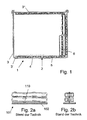
- a heat exchanger 1 serving as an exhaust gas cooler has a housing 2, which is formed by a sandwich structure consisting of a plurality of metal sheets 3, 4 and 5.
- the outer sheet 3 forms with its outer surface the outer surface of the heat exchanger. 1
- the outer metal sheet 3 has a trough-shaped region 3 'and a cover 3 "which closes it, in each case parallel to the outer metal sheet 3 extending, that is both in the trough-shaped region 3 'and in the region of the lid 3 ", the middle provided with a ribbed sheet metal 4 and on the inside thereof, the inner plate 5 are arranged and soldered together, the sheets 4 and 5 shorter than the outer sheet 3 are formed.
- the tube bundle 6 of the exhaust gas cooler are arranged.
- the outermost tube of the tube bundle 6 in each case directly against the inner surface of the inner plate 5 and is soldered to the same.
- the joining or soldering of the heat exchanger 1 is carried out in a known manner in one operation.
- the second flow channel is assigned as the outermost region thereof also the hollow space of the housing 2 which is hollow on the basis of the rib structure of the middle plate 4, so that here too a corresponding pressure prevails.
- a stack of disc pairs is arranged inside a corresponding multi-part housing instead of the tube bundle 6, which form the first flow channel in its interior and the second flow channel in the spaces and the spaces to the outermost metal sheet.
Landscapes
- Engineering & Computer Science (AREA)
- Physics & Mathematics (AREA)
- Thermal Sciences (AREA)
- Mechanical Engineering (AREA)
- General Engineering & Computer Science (AREA)
- Heat-Exchange Devices With Radiators And Conduit Assemblies (AREA)
Description
- Die Erfindung betrifft einen Wärmeübertrager in Rohrbündelbauweise oder in Scheibenbauweise gemäß dem Oberbegriff des Anspruchs 1.
DE-A1- 4 334 768 zeigt einen derartigen Wärmeübertrager. - Auf Grund der immer größer werdenden Belastungen in Hinblick auf Druck und Temperatur werden immer größere Anforderungen bezüglich der Festigkeit von Wärmeübertragem gestellt. Ein Kernproblem hierbei ist der Druckunterschied zwischen Primärmedium in den im Wärmeübertrager hierfür vorgesehenen Strömungskanälen und Sekundärmedium in den jeweils benachbarten Strömungskanälen. Üblicherweise erfolgt die Trennung zwischen Primär- und Sekundärmedium durch relativ dünne Blechwände, die von sich aus den Druckunterschied zwischen den beiden Medien nicht tragen können, so dass dickere Wandstärken erforderlich sind, welche jedoch Nachteile, beispielsweise in Hinblick auf die Material- und Herstellungskosten, sowie in Hinblick auf das Gesamtgewicht, mit sich bringen.
- Normalerweise ist der Wärmeübertrager so aufgebaut, dass sich die Strömungskanäle des Primär und Sekundärmediums abwechseln, so dass auf beiden Seiten der inneren Strömungskanäle das Druckniveau des anderen Mediums anliegt. Durch Einbringen von Stützstrukturen in einen Strömungskanal kann dieser gegen Überdruck von der anderen Seite abgestützt werden. Da der Druck auf beiden Seiten des Kanals gleich ist, stützen sich die gegenüberliegenden Strömungskanalwände über die Stützstrukturen gegenseitig ab. Werden in beide Strömungskanäle, das heißt in die Strömungskanäle des Primärmediums und die Strömungskanäle des Sekundärmediums, Stützstrukturen eingebracht, so sind alle Strömungskanäle gegen Überdruck von der Außenseite abgestützt, der Wärmeübertrager ist somit für Überdruck des Primärmediums gegenüber dem Sekundärmedium und umgekehrt ausgelegt. Ist die Stützstruktur fest mit den Strömungskanalwänden verbunden, dann bewirkt sie eine Versteifung sowohl gegen Überdruck von außen in Folge der Abstützung, aber auch gegen Überdruck innerhalb des Strömungskanals, indem sie als Zuganker zwischen den beiden gegenüberliegenden Strömungskanalwänden wirkt. Üblicherweise werden Rippenstrukturen, Abstützbleche oder Abstütznoppen/-sicken verwendet.
- Ein Beispiel einer bekannten Rohrbündelbauweise mit Noppenabstützung ist in den
Figuren 2a und 2b dargestellt. Im Inneren des Wärmeübertragers 101 führt eine derartige Versteifung mit Noppen 110 zu einer sehr druckstabilen Struktur, da ein symmetrischer Lastfall mit gleichen Drücken an jeweils gegenüberliegenden Strömungskanalwänden anliegt. Problematisch sind jedoch die äußeren Strömungskanäle, da dem Druck auf der Strömungskanalaußenseite nur der Umgebungsdruck beziehungsweise die selbst nicht abgestütze Gehäusewand 102 gegenübersteht. Somit besteht die Gefahr einer Beschädigung des äußersten Strömungskanals in Folge der Druckdifferenz. Ferner kann sich der äußerste Strömungskanal in Folge des hohen Innendrucks aufblähen, so dass sich die Form verändert, sich der Strömungskanal verschiebt und/oder nicht mehr symmetrisch abstützt, was sich auch auf die benachbarten Strömungskanäle auswirkt, so dass sich der gesamte Wärmeübertrager einschließlich dem Gehäuse "aufbläst". Auf Grund der Dehnungen kann die Lebensdauer des Wärmetauschers erheblich verringert werden. Zur Erhöhung der Stabilität ist das Gehäuse 102 relativ dick ausgebildet, was unter anderem zu einem hohen Gewicht führt. - Um ein Aufblasen zu verhindern, wird für einen Ölkühler in Scheibenbauweise in der
DE 197 11 258 C2 anliegend an die äußerste Scheibe eine dicker ausgebildete Grundplatte vorgesehen, welche - abgesehen von der Dicke - in ihrer Form etwa der Form der äußersten Scheibe entspricht. Diese Grundplatte hat jedoch den Nachteil eines hohen Gewichts. - Es ist Aufgabe der Erfindung, einen verbesserten Wärmeübertrager zur Verfügung zu stellen.
- Diese Aufgabe wird gelöst durch einen Wärmeübertrager mit den Merkmalen des Anspruchs 1. Vorteilhafte Ausgestaltungen sind Gegenstand der Unteransprüche.
- Erfindungsgemäß ist ein Wärmeübertrager vorgesehen, insbesondere in Rohrbündel-, Platten- oder Scheibenbauweise, wobei der Wärmeübertrager ein Gehäuse aufweist, in welchem eine Mehrzahl von Strömurigskanälen für ein Primärmedium und ein Sekundärmedium ausgebildet sind, und das Gehäuse in Sandwich-Bauweise ausgebildet ist. Dabei ist der Wärmeübertrager bevorzugt ein Abgaskühler. Anstelle eines Abgaskühlers kann auch ein beliebiger anderer entsprechend aufgebauter Wärmeübertrager, beispielsweise ein Ladeluft-/Kühlmittel-Kühler oder ein Ölkühler, verwendet werden.
- Das Gehäuse ist bevorzugt durch mindestens zwei, vorzugsweise drei Bleche gebildet, wobei die Außenfläche des äußeren Blechs die Gehäuseaußenfläche bildet. Das innere Blech ist bevorzugt von dem äußeren Blech beabstandet, wobei zwischen dem äußeren Blech und dem inneren Blech vorzugsweise ein mittleres Blech angeordnet ist, welches eine Rippenstruktur aufweist. An Stelle einer Rippenstruktur sind auch andere die beiden Bleche beabstandende Strukturen, wie beispielsweise Noppen/Sicken, möglich.
- Die Bleche sind bevorzugt miteinander verlötet. Dabei kann das Verlöten bevorzugt in einem einzigen Arbeitsgang erfolgen, wofür die Bleche entsprechend vor dem Zusammenbau vorbereitet sind.
- Im Gehäuse sind vorzugsweise innerhalb des inneren Blechs Rohrbündel, Platten oder Scheibenstapel angeordnet, welche dem Wärmeaustausch zwischen den beiden Betriebsmedien dienen.
- Zwischen dem äußeren Blech und dem inneren Blech ist vorzugsweise ein Strömungskanal für eines der Betriebsmedien vorgesehen, so dass sich dieses Betriebsmedium auch außerhalb des Bereichs, in welchem die eigentlichen Wärmetauscherstrukturen, wie beispielsweise Rohrbündel, vorgesehen sind, befindet und ein entsprechender Druck herrscht.
- Durch die erfindungsgemäße Ausgestaltung des Gehäuses können an Stelle einer einfachen Gehäusewand mit großer Wanddicke bei etwa gleichen Kosten deutlich dünnere Materialstärken verwendet werden, welche bei einem derartigen Aufbau eine erhöhte Festigkeit zeigen. Bei vergleichbaren Festigkeiten kann das Baugewicht gegenüber herkömmlichen Gehäusen deutlich verringert werden. Ferner sind die Bauteile im unverlöteten Zustand vergleichsweise flexibel und können einfach verformt werden, da keine Versikkungen oder ähnliches erforderlich sind. Durch die relativ großflächig ebenen Flächen wird die Anbindung an die benachbarten Bauteile im Gehäuse, zum Beispiel durch Verlötung, unterstützt. Bei Bedarf können mit geringen Spann- oder Gewichtskräften während des Lötprozesses Spaltmaße eingestellt werden, die eine flächige Verlötung der beiden äußeren Bleche mit der dazwischenliegenden Rippenstruktur zum Gehäuse gewährleisten. Erst im verlöteten Zustand ergibt sich eine Struktur mit einer großen Biegesteifigkeit.
- Unter Umständen vorteilhaft ist ein Gehäuse mit genau zwei Blechen, von denen mindestens eines besonders bevorzugt mit Abstandshaltern wie Rippen, Stegen, Wellen, Noppen oder dergleichen versehen ist. Eine Verringerung der Anzahl der Bleche vereinfacht die Fertigung des Wärmeübertragers.
- Ebenfalls eine Vereinfachung der Fertigung ist unter Umständen dadurch erreichbar, daß gemäß einer bevorzugten Ausgestaltung das Gehäuse nur auf zwei Seiten beziehungsweise in zwei einander gegenüberliegenden Gehäusebereichen in Sandwich-Bauweise ausgebildet ist.
- Im Folgenden wird die Erfindung anhand eines Ausführungsbeispiels mit Variante, teilweise unter Bezugnahme auf die Zeichnung, im Einzelnen erläutert. In der Zeichnung zeigen:
- Fig. 1
- einen Schnitt mit nur teilweise dargestellter Innenstruktur durch einen erfindungsgemäßen Wärmetauscher, und
- Fig. 2a,
- jeweils einen ausschnittsweisen Schnitt in verschiedenen Richtungen durch einen Wärmeübertrager in Rohrbündelbauweise mit Noppenabstützung gemäß dem Stand der Technik.
- Ein als Abgaskühler dienender Wärmeübertrager 1 weist ein Gehäuse 2 auf, welches durch eine aus mehreren Blechen 3, 4 und 5 bestehende SandwichStruktur gebildet ist. Das äußere Blech 3 bildet mit seiner Außenfläche die Außenfläche des Wärmeübertragers 1.
- Das äußere Blech 3 weist einen wannenförmigen Bereich 3' und einen diesen verschließenden Deckel 3" auf. Jeweils parallel zu dem äußeren Blech 3 verlaufend, das heißt sowohl im wannenförmigen Bereich 3' als auch im Bereich des Deckels 3", sind das mittlere mit einer Rippenstruktur versehene Blech 4 und auf der Innenseite hiervon das innere Blech 5 angeordnet und miteinander verlötet, wobei die Bleche 4 und 5 kürzer als das äußere Blech 3 ausgebildet sind.
- Innerhalb von dem inneren Blech 5 sind die Rohrbündel 6 des Abgaskühlers angeordnet. Dabei liegt das äußerste Rohr des Rohrbündels 6 jeweils direkt an der Innenfläche des inneren Blechs 5 an und ist mit demselben verlötet. Das Fügen beziehungsweie Verlöten des Wärmeübertragers 1 erfolgt auf an sich bekannte Weise in einem Arbeitsgang.
- Ein erster Strömungskanal, vorliegend für das zu kühlende Medium, nämlich das Abgas (Primärmedium), wird durch den Innenraum der Rohrbündel 6 und ein zweiter Strömungskanal, vorliegend für das Kühlmedium (Sekundärmedium), wird durch die Zwischenräume zwischen den Rohrbündeln 6 gebildet. Dem zweiten Strömungskanal ist als äußerstem Bereich desselben auch der auf Grund der Rippenstruktur des mittleren Blechs 4 hohl ausgebildeten Zwischenraums des Gehäuses 2 zugeordnet, so dass auch hier ein entsprechender Druck herrscht.
- Gemäß einer nicht in der Zeichnung dargestellten Variante ist im Inneren eines entsprechend mehrteilig ausgebildeten Gehäuses anstelle der Rohrbündel 6 ein Stapel von Scheibenpaaren angeordnet, die in ihrem Inneren den ersten Strömungskanal und in den Zwischenräumen sowie den Zwischenräumen zum äußersten Blech den zweiten Strömungskanal bilden.
-
- 1, 101 Wärmeübertrager
- 2, 102 Gehäuse
- 3 äußeres Blech
- 3' wannenförmiger Bereich
- 3" Deckel
- 4 mittleres Blech
- 5 inneres Blech
- 6 Rohrbündel
- 110 Noppe
Claims (8)
- Wärmeübertrager, insbesondere in Rohrbündel, Platten- oder Scheibenbauweise, wobei der Wärmeübertrager (1) ein Gehäuse (2) aufweist in welchem eine Mehrzahl von Strömungskanälen für ein Primärmedium und ein Sekundärmedium ausgebildet sind, wobei das Gehäuse (2) zumindest bereichsweise, insbesondere im wesentlichen durchgehend, in Sandwich-Bauweise ausgebildet ist dadurch gekennzeichnet, daβ
das Gehäuse (2) in Sandwich-Bauweise eine durch ein mittleres Blech gebildete (4) Rippenstruktur umfasst, die zwischen einem äußeren Blech (3) und einem inneren Blech (5) angeordnet ist und
Rippenstruktur zwischen dem äußeren Blech (3) und dem inneren Blech (5) eingelötet oder -geschweißt ist. - Wärmeübertrager nach Anspruch 1, dadurch gekennzeichnet, dass das Gehäuse (2) in Sandwich-Bauweise durch mindestens zwei Bleche (3, 4, 5) gebildet ist, wobei die Außenfläche des äußeren Blechs (3) die Gehäuseaußenfläche bildet.
- Wärmeübertrager nach Anspruch 1 oder 2, dadurch gekennzeichnet, dass das Gehäuse (2) in Sandwich-Bauweise durch mindestens zwei Bleche (3, 4, 5) gebildet ist, wobei das innere Blech (5) von dem die Gehäuseaußenfiläche bildenden äußeren Blech (3) beabstandet ist.
- Wärmeübertrager nach einem der vorhergehenden Ansprüche, dadurch gekennzeichnet dass im Gehäuse (2) in Sandwich-Bauweise zwischen dem äußeren Blech (3) und dem inneren Blech (5) ein Strömungskanal für eines der Betriebsmedien vorgesehen ist
- Wärmeübertrager nach einem der vorhergehenden Ansprüche, dadurch gekennzeichnet, dass im Gehäuse (2) in Sandwich-Bauweise innerhalb des inneren Blechs (5) Rohrbündel, Platten oder Scheibenstapel angeordnet sind.
- Wärmeübertragers nach einem der vorhergehenden Ansprüche, dadurch gekennzeichnet, dass das Gehäuse zumindest bereichsweise genau zwei Bleche aufweist, die insbesondere mit Abstandshaltern wie Rippen, Stegen, Wollen, Noppen oder dergleichen versehen sind.
- Wärmeübertrager nach einem der vorhergehenden Ansprüche, dadurch gekennzeichnet, dass das Gehäuse jeweils in einander gegenüberliegend angeordneten Gehäusebereichen, insbesondere in zwei Gehäusebereichen, in Sandwich-Bauweise ausgebildet ist.
- Verwendung eines Wärmeübertragers (1) gemäß einem der Ansprüche 1 bis 7 als Abgaskühler, Ladeluft-/Kühlmittel-Kühler oder Ölkühler.
Applications Claiming Priority (2)
| Application Number | Priority Date | Filing Date | Title |
|---|---|---|---|
| DE102004031567A DE102004031567A1 (de) | 2004-06-29 | 2004-06-29 | Wärmeübertrager |
| PCT/EP2005/006961 WO2006000457A1 (de) | 2004-06-29 | 2005-06-29 | Wärmeübertarger |
Publications (2)
| Publication Number | Publication Date |
|---|---|
| EP1763652A1 EP1763652A1 (de) | 2007-03-21 |
| EP1763652B1 true EP1763652B1 (de) | 2012-01-25 |
Family
ID=35033460
Family Applications (1)
| Application Number | Title | Priority Date | Filing Date |
|---|---|---|---|
| EP05764150A Expired - Lifetime EP1763652B1 (de) | 2004-06-29 | 2005-06-29 | Wärmeübertarger |
Country Status (5)
| Country | Link |
|---|---|
| US (1) | US20080011465A1 (de) |
| EP (1) | EP1763652B1 (de) |
| AT (1) | ATE543068T1 (de) |
| DE (1) | DE102004031567A1 (de) |
| WO (1) | WO2006000457A1 (de) |
Family Cites Families (25)
| Publication number | Priority date | Publication date | Assignee | Title |
|---|---|---|---|---|
| US2424795A (en) * | 1943-01-15 | 1947-07-29 | Garrett Corp | Reenforced elliptical oil cooler |
| US2526135A (en) * | 1946-04-12 | 1950-10-17 | Gen Motors Corp | Gas regenerator |
| US2767962A (en) * | 1952-10-10 | 1956-10-23 | Louis A Blackburn | Vacuum milk tank |
| US2809019A (en) * | 1954-06-24 | 1957-10-08 | Coleman Co | Cooling apparatus |
| US3024606A (en) * | 1958-07-10 | 1962-03-13 | Curtiss Wright Corp | Liquid cooling system for jet engines |
| US3193919A (en) * | 1961-05-26 | 1965-07-13 | Jr Thomas P M Rouse | Method of fabricating pressure vessels |
| US3612174A (en) * | 1969-06-20 | 1971-10-12 | Gustav Osfselt Hovalwerk Ag | Apparatus having connecting means between containers for preparing consumer water |
| DE2753189A1 (de) * | 1976-11-29 | 1978-06-01 | Holl Res Corp | Oberflaechenausbildung in einer vorrichtung zum fuehren von fluiden |
| DE3444961A1 (de) * | 1984-12-10 | 1986-06-12 | Klöckner-Humboldt-Deutz AG, 5000 Köln | Waermetauscher fuer zwei medien, insbesondere ein ladeluftkuehler fuer eine brennkraftmaschine |
| DD235720A1 (de) * | 1985-03-25 | 1986-05-14 | Messgeraetewerk Zwonitz Veb K | Waermeaustauscher und verfahren zu seiner herstellung |
| US4655367A (en) * | 1985-09-12 | 1987-04-07 | Palazzo David T | Double wall storage tank for liquids |
| DE3637796A1 (de) * | 1986-11-06 | 1988-05-11 | Bavaria Anlagenbau Gmbh | Kreuzstrom-plattenwaermetauscher |
| EP0300286A3 (de) * | 1987-07-22 | 1989-06-07 | Firmenich Sa | Mehrschichtige Sandwichbahn und ihre Anwendung für Verpackungen |
| NL193255C (nl) * | 1992-10-23 | 1999-04-02 | Atag Verwarming Bv | Warmtewisselaar. |
| DE4333904C2 (de) * | 1993-09-27 | 1996-02-22 | Eberhard Dipl Ing Paul | Kanalwärmetauscher |
| JP3353475B2 (ja) * | 1994-07-28 | 2002-12-03 | 株式会社デンソー | 熱交換器 |
| JPH08327281A (ja) * | 1995-05-30 | 1996-12-13 | Sanden Corp | 熱交換器のヘッダ |
| DE19519740B4 (de) * | 1995-06-02 | 2005-04-21 | Mann + Hummel Gmbh | Wärmetauscher |
| DE19621032A1 (de) * | 1996-05-22 | 1997-11-27 | Schatz Thermo System Gmbh | Wärmespeicher, insbesondere für Kraftfahrzeuge, mit einem doppelwandigen Isolierbehälter |
| DE19711258C2 (de) * | 1997-03-18 | 1999-09-02 | Behr Gmbh & Co | Stapelscheiben-Ölkühler |
| FR2769697B1 (fr) * | 1997-10-10 | 1999-12-31 | Soc Et Et De Const Aero Navale | Echangeur de chaleur du type a croisement orthogonal de deux fluides |
| JP2001099585A (ja) * | 1999-09-30 | 2001-04-13 | Denso Corp | アルミニウム製熱交換器 |
| US6889751B1 (en) * | 2000-10-04 | 2005-05-10 | Modine Manufacturing Company | Latent heat storage device |
| JP4180830B2 (ja) * | 2002-02-05 | 2008-11-12 | カルソニックカンセイ株式会社 | 熱交換器 |
| WO2007009713A1 (de) * | 2005-07-19 | 2007-01-25 | Behr Gmbh & Co. Kg | Wärmeübertrager |
-
2004
- 2004-06-29 DE DE102004031567A patent/DE102004031567A1/de not_active Withdrawn
-
2005
- 2005-06-29 AT AT05764150T patent/ATE543068T1/de active
- 2005-06-29 WO PCT/EP2005/006961 patent/WO2006000457A1/de not_active Ceased
- 2005-06-29 EP EP05764150A patent/EP1763652B1/de not_active Expired - Lifetime
- 2005-06-29 US US11/571,403 patent/US20080011465A1/en not_active Abandoned
Also Published As
| Publication number | Publication date |
|---|---|
| WO2006000457A1 (de) | 2006-01-05 |
| US20080011465A1 (en) | 2008-01-17 |
| DE102004031567A1 (de) | 2006-02-02 |
| EP1763652A1 (de) | 2007-03-21 |
| ATE543068T1 (de) | 2012-02-15 |
Similar Documents
| Publication | Publication Date | Title |
|---|---|---|
| EP1678455B1 (de) | Stapelscheibenwärmeüberträger, insbesondere ölkühler für kraftfahrzeuge | |
| EP3531055B1 (de) | Plattenwärmetauscher und verfahren zu dessen herstellung | |
| DE69702180T2 (de) | Plattenwärmetauscher mit Rippen | |
| DE2946804C2 (de) | ||
| DE112018004787T5 (de) | Multi-fluid wärmetauscher | |
| DE2250222B2 (de) | Plattenförmige Wärmetauscherwand | |
| DE3423736C2 (de) | ||
| EP2435775B1 (de) | Schichtwärmeübertrager für hohe temperaturen | |
| DE102007049665A1 (de) | Wärmeaustauscher | |
| DE60310992T2 (de) | Hochdruckwärmetauscher | |
| DE10247264A1 (de) | Plattenwärmeübertrager in Stapelbauweise | |
| DE19846518A1 (de) | Wärmetauscher, insbesondere für Gase und Flüssigkeiten | |
| EP1091800A1 (de) | Verfahren zur herstellung eines kompakten katalytischen reaktors | |
| DE102009018247A1 (de) | Plattenwärmeaustauscher mit Profilen | |
| DE102022124354A1 (de) | Wärmeübertrager bestehend aus zwei Arten von Platten | |
| DE2413165A1 (de) | Aufladbarer gegenstromplattenwaermeaustauscher | |
| EP1657512A1 (de) | Wärmetauscher mit offenem Profil als Gehäuse | |
| DE10010737C2 (de) | Radiator für einen elektrischen Transformator | |
| DE102009048103A1 (de) | Wärmetauscher | |
| EP1172624B1 (de) | Plattenwärmetauscher | |
| DE3011011C2 (de) | Plattenwärmetauscher mit in einem Stapel angeordneten rechteckigen Platten | |
| DE102007008341A1 (de) | Wärmeübertrager | |
| DE3637796A1 (de) | Kreuzstrom-plattenwaermetauscher | |
| DE102016210261A1 (de) | Wärmetauscher und Herstellungsverfahren dafür | |
| DE102004031567A1 (de) | Wärmeübertrager |
Legal Events
| Date | Code | Title | Description |
|---|---|---|---|
| PUAI | Public reference made under article 153(3) epc to a published international application that has entered the european phase |
Free format text: ORIGINAL CODE: 0009012 |
|
| 17P | Request for examination filed |
Effective date: 20070129 |
|
| AK | Designated contracting states |
Kind code of ref document: A1 Designated state(s): AT BE BG CH CY CZ DE DK EE ES FI FR GB GR HU IE IS IT LI LT LU MC NL PL PT RO SE SI SK TR |
|
| DAX | Request for extension of the european patent (deleted) | ||
| 17Q | First examination report despatched |
Effective date: 20100602 |
|
| GRAP | Despatch of communication of intention to grant a patent |
Free format text: ORIGINAL CODE: EPIDOSNIGR1 |
|
| GRAS | Grant fee paid |
Free format text: ORIGINAL CODE: EPIDOSNIGR3 |
|
| GRAA | (expected) grant |
Free format text: ORIGINAL CODE: 0009210 |
|
| AK | Designated contracting states |
Kind code of ref document: B1 Designated state(s): AT BE BG CH CY CZ DE DK EE ES FI FR GB GR HU IE IS IT LI LT LU MC NL PL PT RO SE SI SK TR |
|
| REG | Reference to a national code |
Ref country code: GB Ref legal event code: FG4D Free format text: NOT ENGLISH |
|
| REG | Reference to a national code |
Ref country code: CH Ref legal event code: EP |
|
| REG | Reference to a national code |
Ref country code: AT Ref legal event code: REF Ref document number: 543068 Country of ref document: AT Kind code of ref document: T Effective date: 20120215 |
|
| REG | Reference to a national code |
Ref country code: IE Ref legal event code: FG4D |
|
| REG | Reference to a national code |
Ref country code: DE Ref legal event code: R096 Ref document number: 502005012396 Country of ref document: DE Effective date: 20120322 |
|
| REG | Reference to a national code |
Ref country code: NL Ref legal event code: VDEP Effective date: 20120125 |
|
| LTIE | Lt: invalidation of european patent or patent extension |
Effective date: 20120125 |
|
| PG25 | Lapsed in a contracting state [announced via postgrant information from national office to epo] |
Ref country code: NL Free format text: LAPSE BECAUSE OF FAILURE TO SUBMIT A TRANSLATION OF THE DESCRIPTION OR TO PAY THE FEE WITHIN THE PRESCRIBED TIME-LIMIT Effective date: 20120125 Ref country code: IS Free format text: LAPSE BECAUSE OF FAILURE TO SUBMIT A TRANSLATION OF THE DESCRIPTION OR TO PAY THE FEE WITHIN THE PRESCRIBED TIME-LIMIT Effective date: 20120525 Ref country code: LT Free format text: LAPSE BECAUSE OF FAILURE TO SUBMIT A TRANSLATION OF THE DESCRIPTION OR TO PAY THE FEE WITHIN THE PRESCRIBED TIME-LIMIT Effective date: 20120125 Ref country code: BG Free format text: LAPSE BECAUSE OF FAILURE TO SUBMIT A TRANSLATION OF THE DESCRIPTION OR TO PAY THE FEE WITHIN THE PRESCRIBED TIME-LIMIT Effective date: 20120425 |
|
| REG | Reference to a national code |
Ref country code: IE Ref legal event code: FD4D |
|
| PG25 | Lapsed in a contracting state [announced via postgrant information from national office to epo] |
Ref country code: PT Free format text: LAPSE BECAUSE OF FAILURE TO SUBMIT A TRANSLATION OF THE DESCRIPTION OR TO PAY THE FEE WITHIN THE PRESCRIBED TIME-LIMIT Effective date: 20120525 Ref country code: FI Free format text: LAPSE BECAUSE OF FAILURE TO SUBMIT A TRANSLATION OF THE DESCRIPTION OR TO PAY THE FEE WITHIN THE PRESCRIBED TIME-LIMIT Effective date: 20120125 Ref country code: GR Free format text: LAPSE BECAUSE OF FAILURE TO SUBMIT A TRANSLATION OF THE DESCRIPTION OR TO PAY THE FEE WITHIN THE PRESCRIBED TIME-LIMIT Effective date: 20120426 Ref country code: PL Free format text: LAPSE BECAUSE OF FAILURE TO SUBMIT A TRANSLATION OF THE DESCRIPTION OR TO PAY THE FEE WITHIN THE PRESCRIBED TIME-LIMIT Effective date: 20120125 |
|
| PG25 | Lapsed in a contracting state [announced via postgrant information from national office to epo] |
Ref country code: CY Free format text: LAPSE BECAUSE OF FAILURE TO SUBMIT A TRANSLATION OF THE DESCRIPTION OR TO PAY THE FEE WITHIN THE PRESCRIBED TIME-LIMIT Effective date: 20120125 |
|
| PG25 | Lapsed in a contracting state [announced via postgrant information from national office to epo] |
Ref country code: CZ Free format text: LAPSE BECAUSE OF FAILURE TO SUBMIT A TRANSLATION OF THE DESCRIPTION OR TO PAY THE FEE WITHIN THE PRESCRIBED TIME-LIMIT Effective date: 20120125 Ref country code: RO Free format text: LAPSE BECAUSE OF FAILURE TO SUBMIT A TRANSLATION OF THE DESCRIPTION OR TO PAY THE FEE WITHIN THE PRESCRIBED TIME-LIMIT Effective date: 20120125 Ref country code: DK Free format text: LAPSE BECAUSE OF FAILURE TO SUBMIT A TRANSLATION OF THE DESCRIPTION OR TO PAY THE FEE WITHIN THE PRESCRIBED TIME-LIMIT Effective date: 20120125 Ref country code: IE Free format text: LAPSE BECAUSE OF FAILURE TO SUBMIT A TRANSLATION OF THE DESCRIPTION OR TO PAY THE FEE WITHIN THE PRESCRIBED TIME-LIMIT Effective date: 20120125 Ref country code: SE Free format text: LAPSE BECAUSE OF FAILURE TO SUBMIT A TRANSLATION OF THE DESCRIPTION OR TO PAY THE FEE WITHIN THE PRESCRIBED TIME-LIMIT Effective date: 20120125 Ref country code: EE Free format text: LAPSE BECAUSE OF FAILURE TO SUBMIT A TRANSLATION OF THE DESCRIPTION OR TO PAY THE FEE WITHIN THE PRESCRIBED TIME-LIMIT Effective date: 20120125 Ref country code: SI Free format text: LAPSE BECAUSE OF FAILURE TO SUBMIT A TRANSLATION OF THE DESCRIPTION OR TO PAY THE FEE WITHIN THE PRESCRIBED TIME-LIMIT Effective date: 20120125 |
|
| PG25 | Lapsed in a contracting state [announced via postgrant information from national office to epo] |
Ref country code: SK Free format text: LAPSE BECAUSE OF FAILURE TO SUBMIT A TRANSLATION OF THE DESCRIPTION OR TO PAY THE FEE WITHIN THE PRESCRIBED TIME-LIMIT Effective date: 20120125 Ref country code: IT Free format text: LAPSE BECAUSE OF FAILURE TO SUBMIT A TRANSLATION OF THE DESCRIPTION OR TO PAY THE FEE WITHIN THE PRESCRIBED TIME-LIMIT Effective date: 20120125 |
|
| PLBE | No opposition filed within time limit |
Free format text: ORIGINAL CODE: 0009261 |
|
| STAA | Information on the status of an ep patent application or granted ep patent |
Free format text: STATUS: NO OPPOSITION FILED WITHIN TIME LIMIT |
|
| BERE | Be: lapsed |
Owner name: BEHR G.M.B.H. & CO. KG Effective date: 20120630 |
|
| 26N | No opposition filed |
Effective date: 20121026 |
|
| PG25 | Lapsed in a contracting state [announced via postgrant information from national office to epo] |
Ref country code: MC Free format text: LAPSE BECAUSE OF NON-PAYMENT OF DUE FEES Effective date: 20120630 |
|
| REG | Reference to a national code |
Ref country code: CH Ref legal event code: PL |
|
| REG | Reference to a national code |
Ref country code: CH Ref legal event code: PL |
|
| REG | Reference to a national code |
Ref country code: DE Ref legal event code: R097 Ref document number: 502005012396 Country of ref document: DE Effective date: 20121026 |
|
| GBPC | Gb: european patent ceased through non-payment of renewal fee |
Effective date: 20120629 |
|
| PG25 | Lapsed in a contracting state [announced via postgrant information from national office to epo] |
Ref country code: CH Free format text: LAPSE BECAUSE OF NON-PAYMENT OF DUE FEES Effective date: 20120630 Ref country code: GB Free format text: LAPSE BECAUSE OF NON-PAYMENT OF DUE FEES Effective date: 20120629 Ref country code: LI Free format text: LAPSE BECAUSE OF NON-PAYMENT OF DUE FEES Effective date: 20120630 Ref country code: BE Free format text: LAPSE BECAUSE OF NON-PAYMENT OF DUE FEES Effective date: 20120630 Ref country code: ES Free format text: LAPSE BECAUSE OF FAILURE TO SUBMIT A TRANSLATION OF THE DESCRIPTION OR TO PAY THE FEE WITHIN THE PRESCRIBED TIME-LIMIT Effective date: 20120506 |
|
| REG | Reference to a national code |
Ref country code: AT Ref legal event code: MM01 Ref document number: 543068 Country of ref document: AT Kind code of ref document: T Effective date: 20120629 |
|
| PG25 | Lapsed in a contracting state [announced via postgrant information from national office to epo] |
Ref country code: AT Free format text: LAPSE BECAUSE OF NON-PAYMENT OF DUE FEES Effective date: 20120629 |
|
| PG25 | Lapsed in a contracting state [announced via postgrant information from national office to epo] |
Ref country code: TR Free format text: LAPSE BECAUSE OF FAILURE TO SUBMIT A TRANSLATION OF THE DESCRIPTION OR TO PAY THE FEE WITHIN THE PRESCRIBED TIME-LIMIT Effective date: 20120125 |
|
| PG25 | Lapsed in a contracting state [announced via postgrant information from national office to epo] |
Ref country code: LU Free format text: LAPSE BECAUSE OF NON-PAYMENT OF DUE FEES Effective date: 20120629 |
|
| PG25 | Lapsed in a contracting state [announced via postgrant information from national office to epo] |
Ref country code: HU Free format text: LAPSE BECAUSE OF FAILURE TO SUBMIT A TRANSLATION OF THE DESCRIPTION OR TO PAY THE FEE WITHIN THE PRESCRIBED TIME-LIMIT Effective date: 20050629 |
|
| REG | Reference to a national code |
Ref country code: DE Ref legal event code: R082 Ref document number: 502005012396 Country of ref document: DE Representative=s name: GRAUEL, ANDREAS, DIPL.-PHYS. DR. RER. NAT., DE |
|
| REG | Reference to a national code |
Ref country code: DE Ref legal event code: R081 Ref document number: 502005012396 Country of ref document: DE Owner name: MAHLE INTERNATIONAL GMBH, DE Free format text: FORMER OWNER: BEHR GMBH & CO. KG, 70469 STUTTGART, DE Effective date: 20150319 Ref country code: DE Ref legal event code: R081 Ref document number: 502005012396 Country of ref document: DE Owner name: MAHLE INTERNATIONAL GMBH, DE Free format text: FORMER OWNER: BEHR GMBH & CO. KG, 70469 STUTTGART, DE Effective date: 20120131 Ref country code: DE Ref legal event code: R082 Ref document number: 502005012396 Country of ref document: DE Representative=s name: GRAUEL, ANDREAS, DIPL.-PHYS. DR. RER. NAT., DE Effective date: 20150319 |
|
| REG | Reference to a national code |
Ref country code: FR Ref legal event code: PLFP Year of fee payment: 12 |
|
| REG | Reference to a national code |
Ref country code: FR Ref legal event code: PLFP Year of fee payment: 13 |
|
| REG | Reference to a national code |
Ref country code: FR Ref legal event code: PLFP Year of fee payment: 14 |
|
| PGFP | Annual fee paid to national office [announced via postgrant information from national office to epo] |
Ref country code: FR Payment date: 20220625 Year of fee payment: 18 |
|
| PGFP | Annual fee paid to national office [announced via postgrant information from national office to epo] |
Ref country code: DE Payment date: 20230620 Year of fee payment: 19 |
|
| PG25 | Lapsed in a contracting state [announced via postgrant information from national office to epo] |
Ref country code: FR Free format text: LAPSE BECAUSE OF NON-PAYMENT OF DUE FEES Effective date: 20230630 |
|
| REG | Reference to a national code |
Ref country code: DE Ref legal event code: R119 Ref document number: 502005012396 Country of ref document: DE |
|
| PG25 | Lapsed in a contracting state [announced via postgrant information from national office to epo] |
Ref country code: DE Free format text: LAPSE BECAUSE OF NON-PAYMENT OF DUE FEES Effective date: 20250101 |