EP1763238A2 - Image processor, imaging device, and image processing system - Google Patents
Image processor, imaging device, and image processing system Download PDFInfo
- Publication number
- EP1763238A2 EP1763238A2 EP20060250838 EP06250838A EP1763238A2 EP 1763238 A2 EP1763238 A2 EP 1763238A2 EP 20060250838 EP20060250838 EP 20060250838 EP 06250838 A EP06250838 A EP 06250838A EP 1763238 A2 EP1763238 A2 EP 1763238A2
- Authority
- EP
- European Patent Office
- Prior art keywords
- image data
- data
- accordance
- compressed image
- clock signal
- Prior art date
- Legal status (The legal status is an assumption and is not a legal conclusion. Google has not performed a legal analysis and makes no representation as to the accuracy of the status listed.)
- Granted
Links
- 238000003384 imaging method Methods 0.000 title claims description 37
- 238000007906 compression Methods 0.000 claims abstract description 51
- 230000006835 compression Effects 0.000 claims abstract description 43
- 238000006243 chemical reaction Methods 0.000 claims abstract description 12
- 239000000872 buffer Substances 0.000 claims description 45
- 238000010200 validation analysis Methods 0.000 claims description 11
- 238000000034 method Methods 0.000 description 12
- 230000007274 generation of a signal involved in cell-cell signaling Effects 0.000 description 6
- 230000004044 response Effects 0.000 description 6
- 239000003086 colorant Substances 0.000 description 5
- 238000010586 diagram Methods 0.000 description 4
- 230000008569 process Effects 0.000 description 4
- 230000008901 benefit Effects 0.000 description 3
- 230000002035 prolonged effect Effects 0.000 description 3
- 230000005540 biological transmission Effects 0.000 description 2
- 238000004904 shortening Methods 0.000 description 2
- 238000004364 calculation method Methods 0.000 description 1
- 230000008030 elimination Effects 0.000 description 1
- 238000003379 elimination reaction Methods 0.000 description 1
- 239000011159 matrix material Substances 0.000 description 1
- 230000004048 modification Effects 0.000 description 1
- 238000012986 modification Methods 0.000 description 1
- 230000009467 reduction Effects 0.000 description 1
- 230000009466 transformation Effects 0.000 description 1
Images


Classifications
-
- F—MECHANICAL ENGINEERING; LIGHTING; HEATING; WEAPONS; BLASTING
- F01—MACHINES OR ENGINES IN GENERAL; ENGINE PLANTS IN GENERAL; STEAM ENGINES
- F01N—GAS-FLOW SILENCERS OR EXHAUST APPARATUS FOR MACHINES OR ENGINES IN GENERAL; GAS-FLOW SILENCERS OR EXHAUST APPARATUS FOR INTERNAL COMBUSTION ENGINES
- F01N1/00—Silencing apparatus characterised by method of silencing
- F01N1/16—Silencing apparatus characterised by method of silencing by using movable parts
- F01N1/165—Silencing apparatus characterised by method of silencing by using movable parts for adjusting flow area
-
- H—ELECTRICITY
- H04—ELECTRIC COMMUNICATION TECHNIQUE
- H04N—PICTORIAL COMMUNICATION, e.g. TELEVISION
- H04N21/00—Selective content distribution, e.g. interactive television or video on demand [VOD]
- H04N21/20—Servers specifically adapted for the distribution of content, e.g. VOD servers; Operations thereof
- H04N21/23—Processing of content or additional data; Elementary server operations; Server middleware
- H04N21/242—Synchronization processes, e.g. processing of PCR [Program Clock References]
-
- H—ELECTRICITY
- H04—ELECTRIC COMMUNICATION TECHNIQUE
- H04N—PICTORIAL COMMUNICATION, e.g. TELEVISION
- H04N19/00—Methods or arrangements for coding, decoding, compressing or decompressing digital video signals
- H04N19/60—Methods or arrangements for coding, decoding, compressing or decompressing digital video signals using transform coding
-
- H—ELECTRICITY
- H04—ELECTRIC COMMUNICATION TECHNIQUE
- H04N—PICTORIAL COMMUNICATION, e.g. TELEVISION
- H04N21/00—Selective content distribution, e.g. interactive television or video on demand [VOD]
- H04N21/20—Servers specifically adapted for the distribution of content, e.g. VOD servers; Operations thereof
- H04N21/23—Processing of content or additional data; Elementary server operations; Server middleware
- H04N21/234—Processing of video elementary streams, e.g. splicing of video streams or manipulating encoded video stream scene graphs
- H04N21/23406—Processing of video elementary streams, e.g. splicing of video streams or manipulating encoded video stream scene graphs involving management of server-side video buffer
-
- F—MECHANICAL ENGINEERING; LIGHTING; HEATING; WEAPONS; BLASTING
- F01—MACHINES OR ENGINES IN GENERAL; ENGINE PLANTS IN GENERAL; STEAM ENGINES
- F01N—GAS-FLOW SILENCERS OR EXHAUST APPARATUS FOR MACHINES OR ENGINES IN GENERAL; GAS-FLOW SILENCERS OR EXHAUST APPARATUS FOR INTERNAL COMBUSTION ENGINES
- F01N2470/00—Structure or shape of gas passages, pipes or tubes
- F01N2470/02—Tubes being perforated
-
- F—MECHANICAL ENGINEERING; LIGHTING; HEATING; WEAPONS; BLASTING
- F01—MACHINES OR ENGINES IN GENERAL; ENGINE PLANTS IN GENERAL; STEAM ENGINES
- F01N—GAS-FLOW SILENCERS OR EXHAUST APPARATUS FOR MACHINES OR ENGINES IN GENERAL; GAS-FLOW SILENCERS OR EXHAUST APPARATUS FOR INTERNAL COMBUSTION ENGINES
- F01N2470/00—Structure or shape of gas passages, pipes or tubes
- F01N2470/24—Concentric tubes or tubes being concentric to housing, e.g. telescopically assembled
Definitions
- the present invention relates to an image processor.
- imaging elements having over one million pixels, such as a charge coupled device (CCD) and a CMOS image sensor (CiS), are being used in image processing systems such as digital cameras.
- CCD charge coupled device
- SiS CMOS image sensor
- an image processing system includes a camera module and a base band LSI.
- the camera module includes an imaging unit, which includes imaging elements and generates image data for the three primary colors (RGB), and an image processing LSI, which converts the image data to image data in luminance/chrominance (YCbCr) format.
- the base band LSI compresses the image data output from the camera module to generate compressed image data and stores the compressed image data in the image memory.
- the volume of data processed by the image processing LSI and the base band LSI, respectively, and the volume of data provided from the image processing LSI to the base band LSI increase as the number of pixels of the imaging element increases.
- the transfer time of data affects the time necessary until the next photograph can be taken (photographing interval).
- One method for shortening the transfer time is to raise the transfer speed between the image processing LSI and the base band LSI.
- the frequency of a clock signal used for transferring data between the image processing LSI and the base band LSI is increased to raise the transfer speed.
- the employment of an interface enabling response to a high frequency clock signal for the image processing LSI (and base band LSI) increases the cost of the LSIs.
- Japanese Laid-Open Patent Publication No. 2000-078513 describes another method for shortening the transfer time.
- the image data is compressed in compliance with the Joint Photographic Experts Group (JPEG) format with an encoder arranged in the image processing LSI to reduce the volume of data transferred between the image processing LSI and the base band LSI.
- JPEG Joint Photographic Experts Group
- the data length of compressed image data in the JPEG format is not constant.
- the data length differs in accordance with the volume of information (e.g.., depth of color) of each pixel in one frame.
- a conventional input/output circuit operates in accordance with a transfer clock signal having a frequency that is determined so as to enable the transfer of data having the maximum length. Thus, it is difficult to reduce the frequency of the transfer clock signal.
- the operation time of the image processing system be prolonged.
- the operation time is prolonged, it is desired that the power consumption be reduced.
- an increase in the frequency of the transfer clock signal raises power consumption.
- the demand for reduction in power consumption when prolonging the operation time cannot be satisfied.
- an image processor for use with an external device.
- the image processor includes an image processing unit for performing predetermined image processing on image data and outputting processed image data.
- a two-dimensional compression circuit performs a two-dimensional compression process on the processed image data and generates compressed image data.
- a timing signal generator changes frequency of a transfer clock signal in accordance with the compressed image data.
- An output circuit outputs the compressed image data to the external device in accordance with the transfer clock signal.
- an imaging device for use with an external device.
- the imaging device includes an imaging unit for outputting image data in accordance with incident light.
- An image processor connected to the imaging unit, performs predetermined image processing on the image data.
- the image processor includes an image processing unit for performing predetermined image processing on the image data and outputting processed image data.
- a two-dimensional compression circuit performs a two-dimensional compression process on the processed image data and generates compressed image data.
- a timing signal generator connected to the two-dimensional compression circuit, changes frequency of a transfer clock signal in accordance with the compressed image data.
- An output circuit connected to the timing signal generator, outputs the compressed image data to the external device in accordance with the transfer clock signal.
- an image processing system for use with an external device.
- the imaging processing system includes an imaging unit for outputting image data in accordance with incident light.
- An image processor connected to the imaging unit, performs predetermined image processing on the image data.
- a signal processor connected to the image processor and an image memory, stores the image data output from the image processor in the memory.
- the image processor includes an image processing unit for performing predetermined image processing on the image data and outputting processed image data.
- a two-dimensional compression circuit performs a two-dimensional compression process on the processed image data and generates compressed image data.
- a timing signal generator connected to the two-dimensional compression circuit, changes frequency of a transfer clock signal in accordance with the compressed image data.
- An output circuit connected to the timing signal generator, outputs the compressed image data to the external device in accordance with the transfer clock signal.
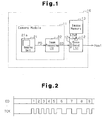
- the image processing system 10 is a digital still camera (DSC) in the preferred embodiment. As shown in Fig. 1, the image processing system 10 includes a camera module 11 functioning as an imaging device, a base band LSI 12 functioning as a signal processor, and an image memory 13.
- DSC digital still camera
- the camera module 11 includes an imaging unit 21 and an image processing LSI 22 functioning as an image processor.
- the imaging unit 21 includes an imaging element 21a for generating an output signal corresponding to incident light.
- the imaging unit 21 A/D converts the output signal of the imaging element 21a to output the image data PD.
- the image' data PD contains color information for the three colors of red (R), green (G), and blue (B) for each pixel.
- the imaging unit 21 includes a color filter and an analog front end circuit.
- the color filter includes a Bayer array of red (R), green (G), and blue (B) filters.
- the imaging element 21a which includes a matrix of a plurality of light receiving cells (pixel), outputs signals charged by each light receiving cell in accordance with the incident light in rows and columns.
- the analog front end circuit A/D converts the output signal of the imaging element to a digital signal and outputs the converted signal as image data PD (Bayer data).
- the image data PD includes data for the colors of red (R), green (G), and blue (B).
- a CCD and a Cis are examples of the imaging element 21a.
- the image processing LSI 22 converts the image data PD of the three primary colors (RGB) to image data S1 (YCbCr data) in a luminance reference format.
- the image data (YCbCr data) S1 contains luminance information Y and color information Cb and Cr. Each data element Y, Cb, and Cr takes the appropriate value.
- the image processing LSI 22 may convert the image data PD to image data S1 (YUV data) containing luminance information Y and color information U and V.
- the image processing LSI 22 performs two-dimensional compression on the YCbCr data S1 through a predetermined coding method such as the Joint Photographic Experts Group (JPEG) method to generate compressed image data ED.
- JPEG Joint Photographic Experts Group
- the image processing LSI 22 then outputs the compressed image data ED.
- the base band LSI 112 includes a camera interface 12a (YUV-I/F).
- the volume of data that is to be transferred (horizontal/vertical size) is set in the camera interface 12a.
- the camera interface 12a receives the set volume of data.
- the image processing LSI 22 transfers the compressed image data ED to the base band LSI 12 in accordance with the transfer method of the camera interface 12a.
- the base band LSI 12 includes a memory interface 12b and stores the compressed image data ED received by the camera interface 12a in the image memory 13 via the memory interface 12b.
- the base band LSI 12 provides image data read from the image memory 13 to a host (not shown) in response to a signal from the host.
- the image processing LSI 22 includes a YCbCr conversion circuit (format conversion circuit) 31 functioning as an image processing unit, line buffers 32a and 32b, a selector 33, a JPEG compression circuit (two-dimensional compression circuit) 34, code buffers 35a and 35b functioning as a storage unit, an output circuit 36, and a timing signal generator 37.
- the image processing LSI 22 is a frame buffer-less LSI which does not include a frame buffer for storing the image data in frame units.
- the YCbCr conversion circuit 31 converts the image data PD of the three primary colors (RGB) to the image data S1, which contains the luminance information Y and the color information Cb and Cr.
- the YCbCr conversion circuit 31 outputs the converted image data S1.
- the converted image data S1 is alternately stored in the first line buffer 32a and the second line buffer 32b.
- the first line buffer 32a and the second line buffer 32b respectively have a capacity enabling the storage of image data for a plurality of lines. The capacity is determined in accordance with the configuration of the imaging element 21a.
- the first and second line buffers 32a and 32b each store the image data of the number of lines (e.g., 8 lines) that is determined in accordance with the processing of the JPEG compression circuit 34.
- the first and the second line buffers 32a and 32b each have a capacity enabling the storage of image data corresponding to the number of horizontal pixels for eight lines of the imaging element 21a.
- the image data S1 for a plurality of lines output from the YCbCr conversion circuit 31 are sequentially written to one of the line buffers (e.g., first line buffer 32a) and then written to the other line buffer when the former line buffer becomes full.
- the selector 33 sequentially reads a predetermined volume of image data from one of the first and second line buffers 32a and 32b that has become full due to the storage of eight lines of data. Then, the selector 33 provides the read predetermined volume of image data S2 to the JPEG compression circuit 34.
- the volume of image data read from the line buffers 32a and 32b is set to a block of 8 x 8 in accordance with the processing by the JPEG compression circuit 34. After reading all of the data from one of the line buffers (e.g., first line buffer 32a), the selector 33 reads the data from the other line buffer that has become full.
- the selector 33 reads the image data stored in the other line buffer. Therefore, the writing of each line of data and the reading of each block of data are alternately performed in each of the first and second line buffers 32a and 32b.
- the JPEG compression circuit 34 performs two-dimensional compression through a predetermined method on the image data sequentially input from the format conversion circuit 31 and generates the compressed image data S3. Specifically, the block data of image data is input to the JPEG compression circuit 34.
- the JPEG compression circuit 34 performs a discrete cosine transformation (DCT) process and a coding process (e.g., Huffman coding) on the block data to output the processed compressed image data S3.
- the compressed image data S3 is data having a variable length.
- the compressed image data S3 are alternately stored in the first code buffer 35a and the second code buffer 35b.
- the first code buffer 35a and the second code buffer 35b have a predetermined capacity (e.g., four kilobytes).
- the first code buffer 35a and the second code buffer 35b writes and reads data in response to a write position signal (write address WA) and a read position signal (read address RA) provided from the timing signal generator 37.
- the first and the second code buffers 35a and 35b sequentially store the compressed image data S3 output from the JPEG compression circuit 34 in accordance with the write address WA.
- the first and the second code buffers 35a and 35b read and output the image data in accordance with the read address RA.
- the output circuit 36 includes a camera interface (YUV interface) 36a.
- the camera interface 36a outputs the image data read from the first and the second code buffers 35a and 35b to the base band LSI 12 shown in Fig. 1 in synchronization with a transfer clock signal TCK provided from the timing signal generator 37.
- the timing signal generator 37 includes a write pointer 41, a read pointer 42, a comparator 43, and a signal generation circuit 44.
- the write pointer 41 generates and outputs the write address so that the compressed codes are sequentially stored in the code buffers 35a and 35b in accordance with the quantity of codes in the compressed image data S3 (compressed codes) that is output from the JPEG compression circuit 34.
- the read pointer 42 generates and outputs the read address RA so that the compressed codes of the code buffers 35a and 35b are sequentially read in accordance with the transfer speed and the transfer timing of the output circuit 36.
- the comparator 43 compares the write address WA and the read address RA and provides the comparison result signal S10 to the signal generation circuit 44. For instance, the comparator 43 outputs a comparison result signal S10 with an H level when the difference between the write address WA and the read address RA is greater than or equal to a predetermined number of addresses, and outputs the comparison result signal S10 with the L level when the difference is less than the predetermined number of addresses.
- the signal generation circuit 44 generates and provides the transfer clock signal TCK to the output circuit 36.
- the signal generation circuit 44 changes the frequency of the transfer clock signal TCK in accordance with the comparison result of the comparator 43.
- the signal generation circuit 44 includes an oscillator (e.g., PLL circuit), two frequency dividers each generating two signals having different frequencies in accordance with the output signal of the oscillator, and a selector for selecting one of the output signals from the two output signals of the two frequency dividers in accordance with the comparison result signal S10 of the comparator 43 and outputting the selected output signal as the transfer clock signal TCK.
- the two output signals of the two frequency dividers each have a first frequency and a second frequency. The first frequency is lower than the second frequency.
- the second frequency is a frequency that enables the transfer of data having the maximum length, as described in the prior art section.
- the selector selects the output signal having the first frequency in response to the comparison result signal S10 with the H level and outputs the selected output signal as the transfer clock signal TCK.
- the selector selects the output signal having the second frequency in response to the comparison result signal S10 with the L level and outputs the selected output signal as the transfer clock signal TCK.
- the timing signal generator 37 changes the frequency of the transfer clock signal TCK in accordance with the difference between the write address WA and the read address RA of the code buffers 35a and 35b or the difference between the write speed and the read speed (refer to Fig. 2).
- the output circuit 36 outputs the image data ED in synchronization with the transfer clock signal TCK.
- the transfer speed is relatively low when the output circuit 36 transfers the image data ED in accordance with the transfer clock signal TCK of the first frequency.
- the transfer speed is relatively high when the output circuit 36 transfers the image data ED in accordance with the transfer clock signal TCK of the second frequency.
- Fig. 2 shows that the frequency of the transfer clock signal TCK is dynamically changed. By changing the frequency of the transfer clock signal TCK, the power consumption in the output circuit 36 is reduced, and the switching noise of the output circuit 36 is reduced.
- the camera interface 36a in the output circuit 36 sets in advance the volume of data to be transferred as the horizontal size and the vertical size for the receiving side (camera interface 12a) and repeatedly outputs blocks containing data corresponding to the horizontal size and the vertical size.
- the volume of image data (code quantity), corresponding to one frame, output from the JPEG compression circuit 34 is not known when the image data PD is input (or when transfer is started).
- the output circuit 36 and the base band LSI 12 set the horizontal size to a fixed value (4K, 2K, or 1K) and set the vertical size to the maximum tolerable value of the camera interface 12a. In this setting, data transfer of the next frame cannot be performed until data having the vertical size, which is set to the maximum value, is transferred.
- the output circuit 36 and the timing signal generator 37 terminates the transfer in accordance with the volume of image data, corresponding to one frame, output from the JPEG compression circuit 34.
- the output circuit 36 generates a plurality of control signals EVS, EHS, EVR, and EHR, as shown in Fig. 3.
- the control signal EVS is a vertical synchronization signal that instructs the start of data transfer in the vertical direction, that is, the start of transfer of one frame of image data.
- the control signal EHS is a horizontal synchronization signal that instructs the start of data transfer in the horizontal direction, that is, the start of transfer of one line (or one block) of image data.
- the control signal EVR is a vertical validation signal that indicates that the data to be transferred in the vertical direction, or that the one frame of image data, is valid.
- the control signal EHR is a horizontal validation signal that indicates that the data to be transferred in the horizontal direction, or the one line (or one block) of image data is valid.
- the one line (one block) of image data includes the data of fixed value.
- the base band LSI 12 performs a receiving operation in synchronization with the vertical synchronization signal EVS and the horizontal synchronization signal EHS and receives data during a period in which the vertical validation signal EVR and the horizontal validation signal HER are active.
- the compressed image data S3 output from the JPEG compression circuit 34 has a variable length.
- the volume of compressed image data output finally during the JPEG compression process for one frame may be less than the volume of data for one line.
- the output circuit 36 adds the data of a predetermined value (e.g., 1) to the compressed image data that is finally output, generates one line of data, and provides the generated data to the base band LSI 12.
- the output circuit 36 negates the vertical validation signal EVR and outputs the vertical synchronization signal EVS when the transfer of one frame of compressed image data is completed, as shown in Fig. 4. This completes the data transfer before the transferred line data reaches the vertical size.
- the transfer of compressed image data is completed within a shorter time period than when transferring data having a vertical size set to the maximum value. This enables the next process to be performed.
- the compressed image data ED (E1, E2, ..., Ex) is line data having a volume of data including the fixed value.
- the number of lines, or line quantity x, from which the line data is taken is determined in accordance with the compression ratio of the compressed data S3 generated by the JPEG compression circuit 34.
- the imaging unit 21 provides the image data PD and the synchronization signals VD and HD to the image processing LSI 22.
- the image processing LSI 22 receives the image data PD (line data P1, P2, ..., Pm,..., Pn) in accordance with the synchronization signals VD and HD.
- the volume of data in each piece of line data P1 to Pn corresponds to the number of pixels in the horizontal direction for one frame.
- the letter n represents the number of lines, or line quantity, from which the line data is taken and is determined in accordance with the number of lines in the vertical direction configuring one frame.
- the signal output from the selector 33 that is, the signal output from the YCbCr conversion circuit 31 is input to the output circuit 36.
- This signal contains luminance information Y and color information Cb and Cr.
- the output circuit 36 has a first mode for outputting the luminance information Y and the color information Cb and Cr, and a second mode for outputting the compressed image data ED.
- the switching between modes is performed in accordance with a mode switching signal provided from an external circuit (not shown).
- the preferred embodiment has the advantages described below.
- the output order of the compressed image data may be changed when necessary.
- the compressed image data ED (code Cd[0], Cd[1], Cd[2], ..., Cd[7]) is continuously output in synchronization with the transfer clock signal TCK.
- Fig. 5(B) shows a JPEG code image.
- the data length of each code Cd[0] ... is eight bits.
- the compressed image data ED (code Cd[0], Cd[1], ...) and the dummy data DMY may be alternately output in synchronization with the transfer clock signal TCK,.
- Fig. 6(B) shows a JPEG code image.
- the image data (YCbCr data) containing the luminance information and the color information transferred in the camera interface 36a
- information regarding details not noticeable to the human eye may be eliminated to reduce the entire data volume.
- the "Y” image data is used, and the color information is eliminated with the "Cb” and “Cr” image data in the main operating direction.
- Such an elimination technique is referred to as "4:2:2”. That is, the volumes of the "Cb” and “Cr” image data are respectively reduced by half with respect to the data volume of the "Y” image data.
- the "Cb” image data and the “Cr” image data are alternately output between the "Y" image data in the camera interface 36a.
- the transfer of each piece of image data for one frame ends at substantially the same time.
- each piece of image data (“Y” image data, "Cb” image data, “Cr” image data) is sequentially stored in a different region.
- Fig. 5(A) data is not stored in the arrangement shown in Fig. 5(B) since the received compressed image data is stored in different regions in the base band LSI, which is set to receive the image data containing luminance information and color information. Therefore, the setting of the storage region must be changed when receiving the compressed image data and when receiving the image data containing the luminance information and the color information.
- the base band LSI set to receive the image data containing the luminance information and the color information stores the received compressed image data in the arrangement shown in Fig. 6(B) and sequentially stores the data in the same region. Therefore, the setting of the region for storing does not need to be changed when receiving the compressed image data and when receiving the image data containing the luminance information and the color information.
- the base band LSI is able to receive the compressed image data without changing (adding) the setting of the conventional base band LSI for receiving the image data containing the luminance information and the color information.
- the image processing LSI may have a mode for outputting the data in the order shown in Fig. 5(A) and a mode for outputting the data in the order shown in Fig. 6(A), and the modes may be switched in accordance with the setting information.
- the image processing LSI corresponds to the base band LSI, for receiving the image data containing the luminance information and the color information, and the base band LSI, for continuously receiving the compressed image data.
- the frequency of the transfer clock signal TCK may be changed in accordance with the code quantity of the compressed image data S3 (compressed code) output from the JPEG compression circuit 34.
- the image processing LSI 51 may include a timing signal generator 52, as shown in Fig. 7.
- the timing signal generator 52 includes a compression ratio calculation circuit 53 for calculating the average compression ratio in accordance with the code quantity of the image data S2 input to the JPEG compression circuit 34 and the code quantity of the image data S3 output from the JPEG compression circuit 34.
- the signal generation circuit 44 changes the frequency of the transfer clock signal TCK in accordance with the calculated average compression ratio S11.
- the frequency of the transfer clock signal TCK may be changed in accordance with the average value of the code quantity of the image data output from the JPEG compression circuit 34 (code quantity of the compressed image data generated by the data of 8x8 pixel block) and the code quantity of the image data output in correspondence with a plurality of blocks.
- the frequency of the transfer clock signal TCK may be changed to three or more different frequencies.
- the comparator 43 may, for example, compare the write address WA and the read address RA and output a signal including a plurality of bits in accordance with the comparison result. As the frequency of the transfer clock signal TCK changes in fine steps in accordance with the code quantity of the compressed image data output from the JPEG compression circuit 34, power consumption and noise are efficiently reduced.
Landscapes
- Engineering & Computer Science (AREA)
- Multimedia (AREA)
- Signal Processing (AREA)
- Chemical & Material Sciences (AREA)
- Combustion & Propulsion (AREA)
- Mechanical Engineering (AREA)
- General Engineering & Computer Science (AREA)
- Compression Or Coding Systems Of Tv Signals (AREA)
- Compression Of Band Width Or Redundancy In Fax (AREA)
- Studio Devices (AREA)
- Image Processing (AREA)
Abstract
Description
- This application is based upon and claims the benefit of priority from prior
Japanese Patent Application No. 2005-248271, filed on August 29, 2005 - The present invention relates to an image processor.
- Recently, imaging elements having over one million pixels, such as a charge coupled device (CCD) and a CMOS image sensor (CiS), are being used in image processing systems such as digital cameras. Thus, high-speed data transfer is required for an image processor and a signal processor that processes the image data output from the imaging elements.
- Generally, an image processing system includes a camera module and a base band LSI. The camera module includes an imaging unit, which includes imaging elements and generates image data for the three primary colors (RGB), and an image processing LSI, which converts the image data to image data in luminance/chrominance (YCbCr) format. The base band LSI compresses the image data output from the camera module to generate compressed image data and stores the compressed image data in the image memory.
- The volume of data processed by the image processing LSI and the base band LSI, respectively, and the volume of data provided from the image processing LSI to the base band LSI increase as the number of pixels of the imaging element increases. The transfer time of data affects the time necessary until the next photograph can be taken (photographing interval).
- One method for shortening the transfer time is to raise the transfer speed between the image processing LSI and the base band LSI. The frequency of a clock signal used for transferring data between the image processing LSI and the base band LSI is increased to raise the transfer speed. However, the employment of an interface enabling response to a high frequency clock signal for the image processing LSI (and base band LSI) increases the cost of the LSIs.
-
Japanese Laid-Open Patent Publication No. 2000-078513 - However, the data length of compressed image data in the JPEG format is not constant. For example, the data length differs in accordance with the volume of information (e.g.., depth of color) of each pixel in one frame. A conventional input/output circuit operates in accordance with a transfer clock signal having a frequency that is determined so as to enable the transfer of data having the maximum length. Thus, it is difficult to reduce the frequency of the transfer clock signal.
- It is also required that the operation time of the image processing system be prolonged. When the operation time is prolonged, it is desired that the power consumption be reduced. However, an increase in the frequency of the transfer clock signal raises power consumption. Thus, the demand for reduction in power consumption when prolonging the operation time cannot be satisfied.
- Accordingly, it is a consideration of the present invention to provide an image processor for lowering the transfer speed and reducing power consumption.
- According to a first aspect of the present invention, there is provided an image processor for use with an external device. The image processor includes an image processing unit for performing predetermined image processing on image data and outputting processed image data. A two-dimensional compression circuit performs a two-dimensional compression process on the processed image data and generates compressed image data. A timing signal generator changes frequency of a transfer clock signal in accordance with the compressed image data. An output circuit outputs the compressed image data to the external device in accordance with the transfer clock signal.
- In an embodiment of the present invention, there is provided an imaging device for use with an external device. The imaging device includes an imaging unit for outputting image data in accordance with incident light. An image processor, connected to the imaging unit, performs predetermined image processing on the image data. The image processor includes an image processing unit for performing predetermined image processing on the image data and outputting processed image data. A two-dimensional compression circuit performs a two-dimensional compression process on the processed image data and generates compressed image data. A timing signal generator, connected to the two-dimensional compression circuit, changes frequency of a transfer clock signal in accordance with the compressed image data. An output circuit, connected to the timing signal generator, outputs the compressed image data to the external device in accordance with the transfer clock signal.
- In an embodiment of the present invention, there is provided an image processing system for use with an external device. The imaging processing system includes an imaging unit for outputting image data in accordance with incident light. An image processor, connected to the imaging unit, performs predetermined image processing on the image data. A signal processor, connected to the image processor and an image memory, stores the image data output from the image processor in the memory. The image processor includes an image processing unit for performing predetermined image processing on the image data and outputting processed image data. A two-dimensional compression circuit performs a two-dimensional compression process on the processed image data and generates compressed image data. A timing signal generator, connected to the two-dimensional compression circuit, changes frequency of a transfer clock signal in accordance with the compressed image data. An output circuit, connected to the timing signal generator, outputs the compressed image data to the external device in accordance with the transfer clock signal.
- The invention, together with advantages thereof, may best be understood by reference to the following description of the presently preferred embodiment together with the accompanying drawings in which:
- Fig. 1 is a partial block circuit diagram of an image processing system including an image processing LSI according to a preferred embodiment of the present invention;
- Fig. 2 is a timing chart of a transfer clock signal and an output signal;
- Fig. 3 is a block diagram of the image processing LSI in the preferred embodiment;
- Fig. 4 is a waveform chart of a signal generated by the image processing LSI;
- Figs. 5(A), 5(B), 6(A), and 6(B) are diagrams showing the operation of the output circuit; and
- Fig. 7 is a block diagram showing a modification of the image processing LSI.
- An
image processing system 10 according to a preferred embodiment of the present invention will now be described. - The
image processing system 10 is a digital still camera (DSC) in the preferred embodiment. As shown in Fig. 1, theimage processing system 10 includes acamera module 11 functioning as an imaging device, abase band LSI 12 functioning as a signal processor, and animage memory 13. - The
camera module 11 includes animaging unit 21 and animage processing LSI 22 functioning as an image processor. Theimaging unit 21 includes animaging element 21a for generating an output signal corresponding to incident light. The imaging unit 21 A/D converts the output signal of theimaging element 21a to output the image data PD. The image' data PD contains color information for the three colors of red (R), green (G), and blue (B) for each pixel. - In addition to the
imaging element 21a, theimaging unit 21 includes a color filter and an analog front end circuit. The color filter includes a Bayer array of red (R), green (G), and blue (B) filters. Theimaging element 21a, which includes a matrix of a plurality of light receiving cells (pixel), outputs signals charged by each light receiving cell in accordance with the incident light in rows and columns. The analog front end circuit A/D converts the output signal of the imaging element to a digital signal and outputs the converted signal as image data PD (Bayer data). For each pixel, the image data PD includes data for the colors of red (R), green (G), and blue (B). A CCD and a Cis (CMOS image sensor) are examples of theimaging element 21a. - The
image processing LSI 22 converts the image data PD of the three primary colors (RGB) to image data S1 (YCbCr data) in a luminance reference format. The image data (YCbCr data) S1 contains luminance information Y and color information Cb and Cr. Each data element Y, Cb, and Cr takes the appropriate value. Theimage processing LSI 22 may convert the image data PD to image data S1 (YUV data) containing luminance information Y and color information U and V. - The
image processing LSI 22 performs two-dimensional compression on the YCbCr data S1 through a predetermined coding method such as the Joint Photographic Experts Group (JPEG) method to generate compressed image data ED. Theimage processing LSI 22 then outputs the compressed image data ED. - The base band LSI 112 includes a
camera interface 12a (YUV-I/F). The volume of data that is to be transferred (horizontal/vertical size) is set in thecamera interface 12a. Thecamera interface 12a receives the set volume of data. Theimage processing LSI 22 transfers the compressed image data ED to thebase band LSI 12 in accordance with the transfer method of thecamera interface 12a. - The
base band LSI 12 includes a memory interface 12b and stores the compressed image data ED received by thecamera interface 12a in theimage memory 13 via the memory interface 12b. Thebase band LSI 12 provides image data read from theimage memory 13 to a host (not shown) in response to a signal from the host. - As shown in Fig. 3, the
image processing LSI 22 includes a YCbCr conversion circuit (format conversion circuit) 31 functioning as an image processing unit, line buffers 32a and 32b, aselector 33, a JPEG compression circuit (two-dimensional compression circuit) 34,code buffers output circuit 36, and atiming signal generator 37. In one embodiment, theimage processing LSI 22 is a frame buffer-less LSI which does not include a frame buffer for storing the image data in frame units. - The
YCbCr conversion circuit 31 converts the image data PD of the three primary colors (RGB) to the image data S1, which contains the luminance information Y and the color information Cb and Cr. TheYCbCr conversion circuit 31 outputs the converted image data S1. The converted image data S1 is alternately stored in thefirst line buffer 32a and thesecond line buffer 32b. Thefirst line buffer 32a and thesecond line buffer 32b respectively have a capacity enabling the storage of image data for a plurality of lines. The capacity is determined in accordance with the configuration of theimaging element 21a. The first and second line buffers 32a and 32b each store the image data of the number of lines (e.g., 8 lines) that is determined in accordance with the processing of theJPEG compression circuit 34. The first and the second line buffers 32a and 32b each have a capacity enabling the storage of image data corresponding to the number of horizontal pixels for eight lines of theimaging element 21a. The image data S1 for a plurality of lines output from theYCbCr conversion circuit 31 are sequentially written to one of the line buffers (e.g.,first line buffer 32a) and then written to the other line buffer when the former line buffer becomes full. - The
selector 33 sequentially reads a predetermined volume of image data from one of the first and second line buffers 32a and 32b that has become full due to the storage of eight lines of data. Then, theselector 33 provides the read predetermined volume of image data S2 to theJPEG compression circuit 34. The volume of image data read from the line buffers 32a and 32b is set to a block of 8 x 8 in accordance with the processing by theJPEG compression circuit 34. After reading all of the data from one of the line buffers (e.g.,first line buffer 32a), theselector 33 reads the data from the other line buffer that has become full. - That is, when the
YCbCr conversion circuit 31 is writing the image data to one of the line buffers, theselector 33 reads the image data stored in the other line buffer. Therefore, the writing of each line of data and the reading of each block of data are alternately performed in each of the first and second line buffers 32a and 32b. - The
JPEG compression circuit 34 performs two-dimensional compression through a predetermined method on the image data sequentially input from theformat conversion circuit 31 and generates the compressed image data S3. Specifically, the block data of image data is input to theJPEG compression circuit 34. TheJPEG compression circuit 34 performs a discrete cosine transformation (DCT) process and a coding process (e.g., Huffman coding) on the block data to output the processed compressed image data S3. The compressed image data S3 is data having a variable length. The compressed image data S3 are alternately stored in thefirst code buffer 35a and thesecond code buffer 35b. - The
first code buffer 35a and thesecond code buffer 35b have a predetermined capacity (e.g., four kilobytes). Thefirst code buffer 35a and thesecond code buffer 35b writes and reads data in response to a write position signal (write address WA) and a read position signal (read address RA) provided from thetiming signal generator 37. The first and thesecond code buffers JPEG compression circuit 34 in accordance with the write address WA. The first and thesecond code buffers - The
output circuit 36 includes a camera interface (YUV interface) 36a. Thecamera interface 36a outputs the image data read from the first and thesecond code buffers base band LSI 12 shown in Fig. 1 in synchronization with a transfer clock signal TCK provided from thetiming signal generator 37. - The
timing signal generator 37 includes awrite pointer 41, aread pointer 42, acomparator 43, and asignal generation circuit 44. - The
write pointer 41 generates and outputs the write address so that the compressed codes are sequentially stored in thecode buffers JPEG compression circuit 34. Theread pointer 42 generates and outputs the read address RA so that the compressed codes of thecode buffers output circuit 36. - The
comparator 43 compares the write address WA and the read address RA and provides the comparison result signal S10 to thesignal generation circuit 44. For instance, thecomparator 43 outputs a comparison result signal S10 with an H level when the difference between the write address WA and the read address RA is greater than or equal to a predetermined number of addresses, and outputs the comparison result signal S10 with the L level when the difference is less than the predetermined number of addresses. - The
signal generation circuit 44 generates and provides the transfer clock signal TCK to theoutput circuit 36. Thesignal generation circuit 44 changes the frequency of the transfer clock signal TCK in accordance with the comparison result of thecomparator 43. In one example, thesignal generation circuit 44 includes an oscillator (e.g., PLL circuit), two frequency dividers each generating two signals having different frequencies in accordance with the output signal of the oscillator, and a selector for selecting one of the output signals from the two output signals of the two frequency dividers in accordance with the comparison result signal S10 of thecomparator 43 and outputting the selected output signal as the transfer clock signal TCK. The two output signals of the two frequency dividers each have a first frequency and a second frequency. The first frequency is lower than the second frequency. The second frequency is a frequency that enables the transfer of data having the maximum length, as described in the prior art section. The selector selects the output signal having the first frequency in response to the comparison result signal S10 with the H level and outputs the selected output signal as the transfer clock signal TCK. The selector selects the output signal having the second frequency in response to the comparison result signal S10 with the L level and outputs the selected output signal as the transfer clock signal TCK. - More specifically, the
timing signal generator 37 changes the frequency of the transfer clock signal TCK in accordance with the difference between the write address WA and the read address RA of thecode buffers output circuit 36 outputs the image data ED in synchronization with the transfer clock signal TCK. The transfer speed is relatively low when theoutput circuit 36 transfers the image data ED in accordance with the transfer clock signal TCK of the first frequency. The transfer speed, on the other hand, is relatively high when theoutput circuit 36 transfers the image data ED in accordance with the transfer clock signal TCK of the second frequency. Fig. 2 shows that the frequency of the transfer clock signal TCK is dynamically changed. By changing the frequency of the transfer clock signal TCK, the power consumption in theoutput circuit 36 is reduced, and the switching noise of theoutput circuit 36 is reduced. - The
camera interface 36a in theoutput circuit 36 sets in advance the volume of data to be transferred as the horizontal size and the vertical size for the receiving side (camera interface 12a) and repeatedly outputs blocks containing data corresponding to the horizontal size and the vertical size. However, the volume of image data (code quantity), corresponding to one frame, output from theJPEG compression circuit 34 is not known when the image data PD is input (or when transfer is started). Theoutput circuit 36 and thebase band LSI 12 set the horizontal size to a fixed value (4K, 2K, or 1K) and set the vertical size to the maximum tolerable value of thecamera interface 12a. In this setting, data transfer of the next frame cannot be performed until data having the vertical size, which is set to the maximum value, is transferred. Theoutput circuit 36 and thetiming signal generator 37 terminates the transfer in accordance with the volume of image data, corresponding to one frame, output from theJPEG compression circuit 34. - More specifically, the
output circuit 36 generates a plurality of control signals EVS, EHS, EVR, and EHR, as shown in Fig. 3. The control signal EVS is a vertical synchronization signal that instructs the start of data transfer in the vertical direction, that is, the start of transfer of one frame of image data. The control signal EHS is a horizontal synchronization signal that instructs the start of data transfer in the horizontal direction, that is, the start of transfer of one line (or one block) of image data. The control signal EVR is a vertical validation signal that indicates that the data to be transferred in the vertical direction, or that the one frame of image data, is valid. - The control signal EHR is a horizontal validation signal that indicates that the data to be transferred in the horizontal direction, or the one line (or one block) of image data is valid. The one line (one block) of image data includes the data of fixed value. The
base band LSI 12 performs a receiving operation in synchronization with the vertical synchronization signal EVS and the horizontal synchronization signal EHS and receives data during a period in which the vertical validation signal EVR and the horizontal validation signal HER are active. - The compressed image data S3 output from the
JPEG compression circuit 34 has a variable length. Thus, the volume of compressed image data output finally during the JPEG compression process for one frame may be less than the volume of data for one line. In this case, theoutput circuit 36 adds the data of a predetermined value (e.g., 1) to the compressed image data that is finally output, generates one line of data, and provides the generated data to thebase band LSI 12. Theoutput circuit 36 negates the vertical validation signal EVR and outputs the vertical synchronization signal EVS when the transfer of one frame of compressed image data is completed, as shown in Fig. 4. This completes the data transfer before the transferred line data reaches the vertical size. Therefore, the transfer of compressed image data is completed within a shorter time period than when transferring data having a vertical size set to the maximum value. This enables the next process to be performed. In Fig. 4, the compressed image data ED (E1, E2, ..., Ex) is line data having a volume of data including the fixed value. The number of lines, or line quantity x, from which the line data is taken is determined in accordance with the compression ratio of the compressed data S3 generated by theJPEG compression circuit 34. - As shown in Fig. 4, the
imaging unit 21 provides the image data PD and the synchronization signals VD and HD to theimage processing LSI 22. Theimage processing LSI 22 receives the image data PD (line data P1, P2, ..., Pm,..., Pn) in accordance with the synchronization signals VD and HD. The volume of data in each piece of line data P1 to Pn corresponds to the number of pixels in the horizontal direction for one frame. The letter n represents the number of lines, or line quantity, from which the line data is taken and is determined in accordance with the number of lines in the vertical direction configuring one frame. - As shown in Fig. 3, the signal output from the
selector 33, that is, the signal output from theYCbCr conversion circuit 31 is input to theoutput circuit 36. This signal contains luminance information Y and color information Cb and Cr. Theoutput circuit 36 has a first mode for outputting the luminance information Y and the color information Cb and Cr, and a second mode for outputting the compressed image data ED. The switching between modes is performed in accordance with a mode switching signal provided from an external circuit (not shown). - The preferred embodiment has the advantages described below.
- (1) The
JPEG compression circuit 34 performs two-dimensional compression on the output data S1 (S2) of theYCbCr conversion circuit 31 to generate the compressed image data S3. Thetiming signal generator 37 changes the frequency of the transfer clock signal TCK in accordance with the compressed image data S2. Theoutput circuit 36 outputs the compressed image data ED in accordance with the transfer clock signal TCK. Since the frequency of the transfer clock signal TCK is low when the volume of the compressed image data ED is small, the transfer speed is lowered, and the power consumption is reduced. - (2) The code buffers 35a and 35b sequentially store the compressed image data S3. The
output circuit 36 sequentially reads and outputs the compressed image data S3 from thecode buffers timing signal generator 37 generates the transfer clock signal TCK having the frequency corresponding to the amount of compressed image data written to thecode buffers code buffers - (3) The interface (camera interface) 36a that outputs data having a fixed length sets the volume of the transferred data in accordance with the transmission destination (base band LSI 12) before starting data transfer. Since the compressed image data has a variable length, the volume of the data is not known before starting data transfer. Thus, the
camera interface 36a sets the value of the maximum volume of compressed image data that can be transmitted as the transferring volume for the transmission destination. Theoutput circuit 36 sequentially outputs plural pieces of line data, with each piece having a predetermined volume (fixed length). The line data is generated by dividing the compressed image data of one frame. Theoutput circuit 36 then outputs the synchronization signals EVS and EHS and the validation signals EVR and EHR for receiving the line data. This ensures that thebase band LSI 12 receives the data in accordance with the synchronization signal and the validation signal. Further, theoutput circuit 36 negates the validation signal EVR after sending the final line data containing the final compressed image data. Thebase band LSI 12 terminates the reception of data in response to the validation signal EVR. The data transfer is completed before the time required to complete the transfer of data having the maximum vertical size would lapse. Thus, useless transfer is not performed. Therefore, the transfer time for one frame of compressed image data is prevented from being prolonged. - (4) The
output circuit 36 generates line data of a predetermined volume with the compressed image data and the dummy data DMY when the amount of data of the final line data does not have the predetermined volume. This equalizes the volume of data of the final line data with the predetermined amount and outputs line data with the fixed length. - (5) The
YCbCr conversion circuit 31 converts the image data input from theimaging unit 21 to the data separated into the luminance information and the color information. TheJPEG compression circuit 34 converts the luminance information and the color information into the compressed image data. Thus, high-speed data transfer is unnecessary, and the output circuit is not required to operate at a high speed. This saves costs and facilitates application to imaging units having a large number of pixels. - It should be apparent to those skilled in the art that the present invention may be embodied in many other specific forms without departing from the scope of the invention. Particularly, it should be understood that the present invention may be embodied in the following forms.
- The output order of the compressed image data may be changed when necessary. For instance, in the output order shown in Fig. 5(A), the compressed image data ED (code Cd[0], Cd[1], Cd[2], ..., Cd[7]) is continuously output in synchronization with the transfer clock signal TCK. Fig. 5(B) shows a JPEG code image. The data length of each code Cd[0] ... is eight bits. Alternatively, in the output order shown in Fig. 6(A), the compressed image data ED (code Cd[0], Cd[1], ...) and the dummy data DMY may be alternately output in synchronization with the transfer clock signal TCK,. Fig. 6(B) shows a JPEG code image.
- In the image data (YCbCr data) containing the luminance information and the color information transferred in the
camera interface 36a, information regarding details not noticeable to the human eye may be eliminated to reduce the entire data volume. For YCbCr data, the "Y" image data is used, and the color information is eliminated with the "Cb" and "Cr" image data in the main operating direction. Such an elimination technique is referred to as "4:2:2". That is, the volumes of the "Cb" and "Cr" image data are respectively reduced by half with respect to the data volume of the "Y" image data. Since the volume of the "Y" image data differs from the volume of the "Cb" and "Cr" image data, the "Cb" image data and the "Cr" image data are alternately output between the "Y" image data in thecamera interface 36a. Thus, the transfer of each piece of image data for one frame ends at substantially the same time. - In the base band LSI receiving the image data (YCbCr data), each piece of image data ("Y" image data, "Cb" image data, "Cr" image data) is sequentially stored in a different region. Thus, when outputting the compressed image data in the order shown in Fig. 5(A), data is not stored in the arrangement shown in Fig. 5(B) since the received compressed image data is stored in different regions in the base band LSI, which is set to receive the image data containing luminance information and color information. Therefore, the setting of the storage region must be changed when receiving the compressed image data and when receiving the image data containing the luminance information and the color information.
- In the output order in which the compressed image data and the dummy data DMY are alternately output, the base band LSI set to receive the image data containing the luminance information and the color information stores the received compressed image data in the arrangement shown in Fig. 6(B) and sequentially stores the data in the same region. Therefore, the setting of the region for storing does not need to be changed when receiving the compressed image data and when receiving the image data containing the luminance information and the color information. The base band LSI is able to receive the compressed image data without changing (adding) the setting of the conventional base band LSI for receiving the image data containing the luminance information and the color information.
- The image processing LSI may have a mode for outputting the data in the order shown in Fig. 5(A) and a mode for outputting the data in the order shown in Fig. 6(A), and the modes may be switched in accordance with the setting information. In such a configuration, the image processing LSI corresponds to the base band LSI, for receiving the image data containing the luminance information and the color information, and the base band LSI, for continuously receiving the compressed image data.
- The frequency of the transfer clock signal TCK may be changed in accordance with the code quantity of the compressed image data S3 (compressed code) output from the
JPEG compression circuit 34. For instance, theimage processing LSI 51 may include atiming signal generator 52, as shown in Fig. 7. Thetiming signal generator 52 includes a compressionratio calculation circuit 53 for calculating the average compression ratio in accordance with the code quantity of the image data S2 input to theJPEG compression circuit 34 and the code quantity of the image data S3 output from theJPEG compression circuit 34. Thesignal generation circuit 44 changes the frequency of the transfer clock signal TCK in accordance with the calculated average compression ratio S11. Further, the frequency of the transfer clock signal TCK may be changed in accordance with the average value of the code quantity of the image data output from the JPEG compression circuit 34 (code quantity of the compressed image data generated by the data of 8x8 pixel block) and the code quantity of the image data output in correspondence with a plurality of blocks. - The frequency of the transfer clock signal TCK may be changed to three or more different frequencies. The
comparator 43 may, for example, compare the write address WA and the read address RA and output a signal including a plurality of bits in accordance with the comparison result. As the frequency of the transfer clock signal TCK changes in fine steps in accordance with the code quantity of the compressed image data output from theJPEG compression circuit 34, power consumption and noise are efficiently reduced. - The present examples and embodiments are to be considered as illustrative and not restrictive, and the invention is not to be limited to the details given herein, but may be modified within the scope of the appended claims.
Claims (13)
- An image processor for use with an external device, the image processor being characterized by:an image processing unit for performing predetermined image processing on image data and outputting processed image data;a two-dimensional compression circuit for performing a two-dimensional compression process on the processed image data and generating compressed image data;a timing signal generator for changing frequency of a transfer clock signal in accordance with the compressed image data; andan output circuit for outputting the compressed image data to the external device in accordance with the transfer clock signal.
- The image processor according to claim 1, further characterized by:a buffer for sequentially storing the compressed image data, wherein the output circuit sequentially reads and outputs the compressed image data stored in the buffer, and the timing signal generator changes the frequency of the transfer clock signal in accordance with volume of the compressed image data written to the buffer and volume of the compressed image data read from the buffer.
- The image processor according to claim 1, further characterized by:a buffer for sequentially storing the compressed image data, wherein the output circuit sequentially reads and outputs the compressed image data stored in the buffer, and the timing signal generator changes the frequency of the transfer clock signal in accordance with a write address of the buffer at which the compressed image data is written and a read address of the buffer from which the compressed image data is read.
- The image processor according to claim 3, wherein the timing signal generator changes the frequency of the transfer clock signal in accordance with the difference between the write address and the read address.
- The image processor according to claim 3, wherein the timing signal generator increases the frequency of the transfer clock signal when the difference between the write address and the read address is large and reduces the frequency of the transfer clock signal when the difference between the write address and the read address is small.
- The image processor according to claim 1, wherein the timing signal generator calculates a compression ratio from the volume of data input to the two-dimensional compression circuit and the volume of data output from the two-dimensional compression circuit to change the frequency of the transfer clock signal in accordance with the compression ratio.
- The image processor according to any one of claims 1 to 6, wherein the output circuit includes an interface for outputting data having a fixed length, and wherein the output circuit:sequentially outputs, via the interface, plural pieces of line data generated by dividing the compressed image data, with each piece of line data having a predetermined volume;outputs a synchronization signal and a validation signal for receiving the line data; andnegates the validation signal after outputting a final piece of the line data containing final compressed image data.
- The image processor according to claim 7, wherein the output circuit generates the line data having the predetermined volume with the compressed image data and dummy data when the volume of the final piece of line data is less than the predetermined volume.
- The image processor according to any one of claims 1 to 8, wherein the image processing unit includes a conversion circuit for converting the image data to data containing luminance information and color information.
- The image processor according to any one of claims 1 to 8, wherein:the output circuit has an interface for outputting data including luminance information and color information; andthe interface alternately outputs line data containing luminance information and line data containing color information, outputs line data containing the compressed image data in lieu of the line data containing the luminance information, and outputs line data containing dummy data in lieu of the line data containing the color information.
- The image processor according to any preceding claim, wherein the image processor is a frame buffer-less LSI.
- An imaging device for use with an external device, the imaging device comprising:an imaging unit for outputting image data in accordance with incident light; andan image processor, connected to the imaging unit, for performing predetermined image processing on the image data, the imaging device being characterized in that the image processor includes:an image processing unit for performing predetermined image processing on the image data and outputting processed image data;a two-dimensional compression circuit for performing a two-dimensional compression process on the processed image data and generating compressed image data;a timing signal generator, connected to the two-dimensional compression circuit, for changing frequency of a transfer clock signal in accordance with the compressed image data; andan output circuit, connected to the timing signal generator, for outputting the compressed image data to the external device in accordance with the transfer clock signal.
- An image processing system for use with an external device, the imaging processing system comprising:an imaging unit for outputting image data in accordance with incident light;an image processor, connected to the imaging unit, for performing predetermined image processing on the image data; anda signal processor, connected to the image processor and an image memory, for storing the image data output from the image processor in the memory, the image processing system being characterized in that the image processor includes:an image processing unit for performing predetermined image processing on the image data and outputting processed image data;a two-dimensional compression circuit for performing a two-dimensional compression process on the processed image data and generating compressed image data;a timing signal generator, connected to the two-dimensional compression circuit, for changing frequency of a transfer clock signal in accordance with the compressed image data; andan output circuit, connected to the timing signal generator, for outputting the compressed image data to the external device in accordance with the transfer clock signal.
Applications Claiming Priority (1)
| Application Number | Priority Date | Filing Date | Title |
|---|---|---|---|
| JP2005248271A JP4368835B2 (en) | 2005-08-29 | 2005-08-29 | Image processing apparatus, imaging apparatus, and image processing system |
Publications (3)
| Publication Number | Publication Date |
|---|---|
| EP1763238A2 true EP1763238A2 (en) | 2007-03-14 |
| EP1763238A3 EP1763238A3 (en) | 2009-07-15 |
| EP1763238B1 EP1763238B1 (en) | 2011-10-05 |
Family
ID=37681683
Family Applications (1)
| Application Number | Title | Priority Date | Filing Date |
|---|---|---|---|
| EP20060250838 Not-in-force EP1763238B1 (en) | 2005-08-29 | 2006-02-16 | Image processor, imaging device, and image processing system |
Country Status (6)
| Country | Link |
|---|---|
| US (1) | US7936375B2 (en) |
| EP (1) | EP1763238B1 (en) |
| JP (1) | JP4368835B2 (en) |
| KR (1) | KR100789221B1 (en) |
| CN (1) | CN100464565C (en) |
| TW (1) | TWI360347B (en) |
Families Citing this family (8)
| Publication number | Priority date | Publication date | Assignee | Title |
|---|---|---|---|---|
| US7954960B2 (en) * | 2007-12-04 | 2011-06-07 | Silicon Quest Kabushiki-Kaisha | Video image display apparatus and timing control method |
| JP4302661B2 (en) * | 2005-05-02 | 2009-07-29 | 富士通マイクロエレクトロニクス株式会社 | Image processing system |
| JP5521778B2 (en) * | 2010-05-26 | 2014-06-18 | 富士通株式会社 | Measuring device and control device |
| JP5720170B2 (en) * | 2010-10-18 | 2015-05-20 | ソニー株式会社 | Image processing apparatus, image processing system, image processing method, and program |
| CN102166780B (en) * | 2011-01-19 | 2012-02-08 | 北京工业大学 | Method for preparing light-transmitting concrete by spinning optical fiber technology |
| JP2014052902A (en) * | 2012-09-07 | 2014-03-20 | Sharp Corp | Memory controller, portable terminal, memory control program and computer readable recording medium |
| US9568985B2 (en) * | 2012-11-23 | 2017-02-14 | Mediatek Inc. | Data processing apparatus with adaptive compression algorithm selection based on visibility of compression artifacts for data communication over camera interface and related data processing method |
| CN108845963A (en) * | 2018-06-08 | 2018-11-20 | 宁波华高信息科技有限公司 | A kind of rapid transmission method of the CIS AFE(analog front end) data based on FPGA |
Citations (1)
| Publication number | Priority date | Publication date | Assignee | Title |
|---|---|---|---|---|
| JPH10108170A (en) | 1996-09-27 | 1998-04-24 | Nec Corp | High efficiency coder |
Family Cites Families (16)
| Publication number | Priority date | Publication date | Assignee | Title |
|---|---|---|---|---|
| WO1995029437A1 (en) * | 1994-04-22 | 1995-11-02 | Sony Corporation | Device and method for transmitting data, and device and method for recording data |
| US6005618A (en) | 1994-07-29 | 1999-12-21 | Sony Corporation | Image pick-up device with control circuit that provides a variable horizontal synchronizing signal |
| JP3037582B2 (en) * | 1995-04-12 | 2000-04-24 | シャープ株式会社 | Digital data buffering device |
| JPH11184889A (en) | 1997-12-25 | 1999-07-09 | Toshiba Corp | Image data management device |
| JP2000078513A (en) | 1998-08-31 | 2000-03-14 | Sony Corp | Image display device and digital camera |
| JP2001166596A (en) | 1999-12-06 | 2001-06-22 | Nec Niigata Ltd | Image forming device and image quality control method |
| JP4329238B2 (en) | 2000-07-05 | 2009-09-09 | ソニー株式会社 | Data stream generating apparatus and method, variable length encoded data stream generating apparatus and method, camera system |
| JP4187425B2 (en) | 2000-09-11 | 2008-11-26 | 富士フイルム株式会社 | Image control apparatus and digital camera |
| JP2002359807A (en) * | 2001-06-01 | 2002-12-13 | Sony Corp | Digital still camera |
| JP2004009540A (en) * | 2002-06-06 | 2004-01-15 | Canon Inc | Printer and its control method |
| JP4076147B2 (en) | 2003-03-19 | 2008-04-16 | 株式会社リコー | Imaging device |
| JP2004297300A (en) | 2003-03-26 | 2004-10-21 | Fuji Photo Film Co Ltd | Image recording apparatus and electronic camera |
| JP2005073077A (en) | 2003-08-26 | 2005-03-17 | Sharp Corp | Solid-state image pickup unit |
| JP4093153B2 (en) * | 2003-09-10 | 2008-06-04 | 富士ゼロックス株式会社 | Decoding device and decoding program |
| JP2005150985A (en) | 2003-11-12 | 2005-06-09 | Sharp Corp | Image information processing system and image information processing method |
| US7482995B2 (en) * | 2004-06-23 | 2009-01-27 | Panasonic Corporation | Control device for a plurality of display devices |
-
2005
- 2005-08-29 JP JP2005248271A patent/JP4368835B2/en not_active Expired - Fee Related
-
2006
- 2006-02-16 EP EP20060250838 patent/EP1763238B1/en not_active Not-in-force
- 2006-02-16 TW TW95105227A patent/TWI360347B/en not_active IP Right Cessation
- 2006-02-27 US US11/362,153 patent/US7936375B2/en not_active Expired - Fee Related
- 2006-03-07 CN CNB2006100569732A patent/CN100464565C/en not_active Expired - Fee Related
- 2006-03-10 KR KR20060022474A patent/KR100789221B1/en active IP Right Grant
Patent Citations (1)
| Publication number | Priority date | Publication date | Assignee | Title |
|---|---|---|---|---|
| JPH10108170A (en) | 1996-09-27 | 1998-04-24 | Nec Corp | High efficiency coder |
Also Published As
| Publication number | Publication date |
|---|---|
| US7936375B2 (en) | 2011-05-03 |
| EP1763238B1 (en) | 2011-10-05 |
| KR20070025929A (en) | 2007-03-08 |
| JP4368835B2 (en) | 2009-11-18 |
| EP1763238A3 (en) | 2009-07-15 |
| TWI360347B (en) | 2012-03-11 |
| CN1925547A (en) | 2007-03-07 |
| CN100464565C (en) | 2009-02-25 |
| KR100789221B1 (en) | 2008-01-02 |
| US20070046683A1 (en) | 2007-03-01 |
| TW200709666A (en) | 2007-03-01 |
| JP2007067572A (en) | 2007-03-15 |
Similar Documents
| Publication | Publication Date | Title |
|---|---|---|
| US9560256B2 (en) | Image capture apparatus and image capture method in which an image is processed by a plurality of image processing devices | |
| US7936375B2 (en) | Image processor, imaging device, and image processing system use with image memory | |
| US9076233B2 (en) | Image processing device and electronic apparatus using the same | |
| JP4187425B2 (en) | Image control apparatus and digital camera | |
| US5920343A (en) | Imaging system with image processing for re-writing a portion of a pixel block | |
| US8502889B2 (en) | Solid-state image capturing device, and image capturing apparatus | |
| JPH1042286A (en) | Device and method for processing image and computer readable memory device | |
| JP2002111989A (en) | Image processing circuit | |
| US20060232808A1 (en) | Imaging module, interface, and method handling multiple simultaneous data types | |
| US7212237B2 (en) | Digital camera with electronic zooming function | |
| US8482438B2 (en) | Data processing device and data processing method | |
| JP4302661B2 (en) | Image processing system | |
| JP2006080860A (en) | Camera and camera image transfer system | |
| US7391932B2 (en) | Apparatus and method for selecting image to be displayed | |
| JP2006304203A (en) | Electronic camera with color difference interleave conversion function | |
| JP3962440B2 (en) | Image processing device | |
| JP4281161B2 (en) | Electronic camera | |
| JP4250511B2 (en) | Imaging device | |
| US20240214593A1 (en) | Image processing device, mobile device, and method of operating the same | |
| JP4905080B2 (en) | Transfer circuit, transfer control method, imaging apparatus, control program | |
| JP2009015332A (en) | Image processing control method | |
| JPH0944634A (en) | Video input device | |
| JP2005159992A (en) | Imaging apparatus and imaging method | |
| JP2001054054A (en) | Picture processor and picture processing method |
Legal Events
| Date | Code | Title | Description |
|---|---|---|---|
| PUAI | Public reference made under article 153(3) epc to a published international application that has entered the european phase |
Free format text: ORIGINAL CODE: 0009012 |
|
| AK | Designated contracting states |
Kind code of ref document: A2 Designated state(s): AT BE BG CH CY CZ DE DK EE ES FI FR GB GR HU IE IS IT LI LT LU LV MC NL PL PT RO SE SI SK TR |
|
| AX | Request for extension of the european patent |
Extension state: AL BA HR MK YU |
|
| RAP1 | Party data changed (applicant data changed or rights of an application transferred) |
Owner name: FUJITSU MICROELECTRONICS LIMITED |
|
| PUAL | Search report despatched |
Free format text: ORIGINAL CODE: 0009013 |
|
| AK | Designated contracting states |
Kind code of ref document: A3 Designated state(s): AT BE BG CH CY CZ DE DK EE ES FI FR GB GR HU IE IS IT LI LT LU LV MC NL PL PT RO SE SI SK TR |
|
| AX | Request for extension of the european patent |
Extension state: AL BA HR MK YU |
|
| 17P | Request for examination filed |
Effective date: 20100111 |
|
| 17Q | First examination report despatched |
Effective date: 20100203 |
|
| AKX | Designation fees paid |
Designated state(s): DE FR GB |
|
| RAP1 | Party data changed (applicant data changed or rights of an application transferred) |
Owner name: FUJITSU SEMICONDUCTOR LIMITED |
|
| GRAP | Despatch of communication of intention to grant a patent |
Free format text: ORIGINAL CODE: EPIDOSNIGR1 |
|
| RIN1 | Information on inventor provided before grant (corrected) |
Inventor name: IGA. KIICHIRO |
|
| GRAS | Grant fee paid |
Free format text: ORIGINAL CODE: EPIDOSNIGR3 |
|
| GRAA | (expected) grant |
Free format text: ORIGINAL CODE: 0009210 |
|
| AK | Designated contracting states |
Kind code of ref document: B1 Designated state(s): DE FR GB |
|
| REG | Reference to a national code |
Ref country code: GB Ref legal event code: FG4D |
|
| REG | Reference to a national code |
Ref country code: DE Ref legal event code: R096 Ref document number: 602006024837 Country of ref document: DE Effective date: 20111201 |
|
| PLBE | No opposition filed within time limit |
Free format text: ORIGINAL CODE: 0009261 |
|
| STAA | Information on the status of an ep patent application or granted ep patent |
Free format text: STATUS: NO OPPOSITION FILED WITHIN TIME LIMIT |
|
| 26N | No opposition filed |
Effective date: 20120706 |
|
| GBPC | Gb: european patent ceased through non-payment of renewal fee |
Effective date: 20120216 |
|
| REG | Reference to a national code |
Ref country code: DE Ref legal event code: R097 Ref document number: 602006024837 Country of ref document: DE Effective date: 20120706 |
|
| REG | Reference to a national code |
Ref country code: FR Ref legal event code: ST Effective date: 20121031 |
|
| PG25 | Lapsed in a contracting state [announced via postgrant information from national office to epo] |
Ref country code: FR Free format text: LAPSE BECAUSE OF NON-PAYMENT OF DUE FEES Effective date: 20120229 Ref country code: GB Free format text: LAPSE BECAUSE OF NON-PAYMENT OF DUE FEES Effective date: 20120216 |
|
| REG | Reference to a national code |
Ref country code: DE Ref legal event code: R082 Ref document number: 602006024837 Country of ref document: DE Representative=s name: REICHERT & LINDNER PARTNERSCHAFT PATENTANWAELT, DE |
|
| REG | Reference to a national code |
Ref country code: DE Ref legal event code: R082 Ref document number: 602006024837 Country of ref document: DE Representative=s name: REICHERT & LINDNER PARTNERSCHAFT PATENTANWAELT, DE Effective date: 20150512 Ref country code: DE Ref legal event code: R081 Ref document number: 602006024837 Country of ref document: DE Owner name: SOCIONEXT INC., YOKOHAMA-SHI, JP Free format text: FORMER OWNER: FUJITSU LTD., KAWASAKI-SHI, KANAGAWA-KEN, JP Effective date: 20111010 Ref country code: DE Ref legal event code: R081 Ref document number: 602006024837 Country of ref document: DE Owner name: SOCIONEXT INC., YOKOHAMA-SHI, JP Free format text: FORMER OWNER: FUJITSU SEMICONDUCTOR LIMITED, YOKOHAMA-SHI, KANAGAWA, JP Effective date: 20150512 Ref country code: DE Ref legal event code: R081 Ref document number: 602006024837 Country of ref document: DE Owner name: SOCIONEXT INC., YOKOHAMA-SHI, JP Free format text: FORMER OWNER: FUJITSU LIMITED, KAWASAKI-SHI, KANAGAWA, JP Effective date: 20111010 |
|
| PGFP | Annual fee paid to national office [announced via postgrant information from national office to epo] |
Ref country code: DE Payment date: 20190219 Year of fee payment: 14 |
|
| REG | Reference to a national code |
Ref country code: DE Ref legal event code: R119 Ref document number: 602006024837 Country of ref document: DE |
|
| PG25 | Lapsed in a contracting state [announced via postgrant information from national office to epo] |
Ref country code: DE Free format text: LAPSE BECAUSE OF NON-PAYMENT OF DUE FEES Effective date: 20200901 |