EP1762521A2 - Delivery device in sheet-fed offset rotary printing press - Google Patents
Delivery device in sheet-fed offset rotary printing press Download PDFInfo
- Publication number
- EP1762521A2 EP1762521A2 EP06018584A EP06018584A EP1762521A2 EP 1762521 A2 EP1762521 A2 EP 1762521A2 EP 06018584 A EP06018584 A EP 06018584A EP 06018584 A EP06018584 A EP 06018584A EP 1762521 A2 EP1762521 A2 EP 1762521A2
- Authority
- EP
- European Patent Office
- Prior art keywords
- suction
- sheet
- air
- support member
- discharge unit
- Prior art date
- Legal status (The legal status is an assumption and is not a legal conclusion. Google has not performed a legal analysis and makes no representation as to the accuracy of the status listed.)
- Withdrawn
Links
Images






Classifications
-
- B—PERFORMING OPERATIONS; TRANSPORTING
- B65—CONVEYING; PACKING; STORING; HANDLING THIN OR FILAMENTARY MATERIAL
- B65H—HANDLING THIN OR FILAMENTARY MATERIAL, e.g. SHEETS, WEBS, CABLES
- B65H29/00—Delivering or advancing articles from machines; Advancing articles to or into piles
- B65H29/02—Delivering or advancing articles from machines; Advancing articles to or into piles by mechanical grippers engaging the leading edge only of the articles
- B65H29/04—Delivering or advancing articles from machines; Advancing articles to or into piles by mechanical grippers engaging the leading edge only of the articles the grippers being carried by endless chains or bands
- B65H29/041—Delivering or advancing articles from machines; Advancing articles to or into piles by mechanical grippers engaging the leading edge only of the articles the grippers being carried by endless chains or bands and introducing into a pile
-
- B—PERFORMING OPERATIONS; TRANSPORTING
- B65—CONVEYING; PACKING; STORING; HANDLING THIN OR FILAMENTARY MATERIAL
- B65H—HANDLING THIN OR FILAMENTARY MATERIAL, e.g. SHEETS, WEBS, CABLES
- B65H29/00—Delivering or advancing articles from machines; Advancing articles to or into piles
- B65H29/68—Reducing the speed of articles as they advance
- B65H29/683—Slowing-down from chain delivery
-
- B—PERFORMING OPERATIONS; TRANSPORTING
- B65—CONVEYING; PACKING; STORING; HANDLING THIN OR FILAMENTARY MATERIAL
- B65H—HANDLING THIN OR FILAMENTARY MATERIAL, e.g. SHEETS, WEBS, CABLES
- B65H2220/00—Function indicators
- B65H2220/09—Function indicators indicating that several of an entity are present
-
- B—PERFORMING OPERATIONS; TRANSPORTING
- B65—CONVEYING; PACKING; STORING; HANDLING THIN OR FILAMENTARY MATERIAL
- B65H—HANDLING THIN OR FILAMENTARY MATERIAL, e.g. SHEETS, WEBS, CABLES
- B65H2406/00—Means using fluid
- B65H2406/10—Means using fluid made only for exhausting gaseous medium
- B65H2406/12—Means using fluid made only for exhausting gaseous medium producing gas blast
- B65H2406/122—Nozzles
-
- B—PERFORMING OPERATIONS; TRANSPORTING
- B65—CONVEYING; PACKING; STORING; HANDLING THIN OR FILAMENTARY MATERIAL
- B65H—HANDLING THIN OR FILAMENTARY MATERIAL, e.g. SHEETS, WEBS, CABLES
- B65H2406/00—Means using fluid
- B65H2406/30—Suction means
- B65H2406/32—Suction belts
-
- B—PERFORMING OPERATIONS; TRANSPORTING
- B65—CONVEYING; PACKING; STORING; HANDLING THIN OR FILAMENTARY MATERIAL
- B65H—HANDLING THIN OR FILAMENTARY MATERIAL, e.g. SHEETS, WEBS, CABLES
- B65H2406/00—Means using fluid
- B65H2406/30—Suction means
- B65H2406/36—Means for producing, distributing or controlling suction
- B65H2406/365—Means for producing, distributing or controlling suction selectively blowing or sucking
-
- B—PERFORMING OPERATIONS; TRANSPORTING
- B65—CONVEYING; PACKING; STORING; HANDLING THIN OR FILAMENTARY MATERIAL
- B65H—HANDLING THIN OR FILAMENTARY MATERIAL, e.g. SHEETS, WEBS, CABLES
- B65H2601/00—Problem to be solved or advantage achieved
- B65H2601/30—Facilitating or easing
- B65H2601/32—Facilitating or easing entities relating to handling machine
- B65H2601/324—Removability or inter-changeability of machine parts, e.g. for maintenance
-
- B—PERFORMING OPERATIONS; TRANSPORTING
- B65—CONVEYING; PACKING; STORING; HANDLING THIN OR FILAMENTARY MATERIAL
- B65H—HANDLING THIN OR FILAMENTARY MATERIAL, e.g. SHEETS, WEBS, CABLES
- B65H2801/00—Application field
- B65H2801/03—Image reproduction devices
- B65H2801/21—Industrial-size printers, e.g. rotary printing press
Definitions
- the present invention relates to a delivery device in a sheet-fed offset rotary printing press, which is arranged on the upstream sheet convey direction side of a pile board and comprises a suction unit for decreasing a sheet convey speed.
- a sheet printed by a printing unit is conveyed as it is gripping-changed from the grippers of an impression cylinder to the grippers of delivery chains. After that, the sheet is released from the grippers at the convey terminal end and drops onto a pile board to be stacked there. Since the sheet conveyed by the delivery chains is gripped by the grippers only at its leading edge, the trailing edge of the sheet may flutter. Also, when the sheet is released to drop, an inertia occurs as the sheet travels, and the edge of the sheet may not be aligned when stacked.
- a plurality of suction wheels line up below the sheet under conveyance on the upstream sheet convey direction side of the pile board in the widthwise direction of the sheet.
- the suction wheels have suction surfaces which draw the sheet by suction in slidable contact with it and rotate at a peripheral speed lower than the sheet convey speed.
- the traveling speed of the released sheet that has been gripped by the grippers is decreased.
- double-sided printing if the suction wheels described above are located within a pattern printed on the reverse surface of the sheet, the suction surfaces of the suction wheels damage the image portions printed on the sheet to degrade the printing quality. Hence, the suction wheels must be located in non-image portions which are not printed.
- non-image portions do not exist other than the two ends of the sheet in the widthwise direction or the number of non-image portions is small, the number of suction wheels is limited, and the center of the sheet becomes slack between the suction wheels, that is, so-called middle slack occurs.
- middle slack occurs, the two ends of the sheet may be disengaged from the suction wheels and are not drawn by them by suction, so the sheet convey speed cannot be sufficiently decreased. As a result, the sheet flutters.
- the edge of the sheet is not aligned well, and comes into contact with the brackets of the suction wheels to damage the printing surface.
- an apparatus which comprises a plurality of suction wheels which are arranged in the widthwise direction of a sheet to be conveyed, and at least a pair of nozzles which are arranged below the sheet on the two sides of the sheet to sandwich the center of the sheet in the widthwise direction.
- the pair of nozzles discharge air to blow upward the sheet under conveyance.
- the air discharge directions from the nozzles are directed outwardly in the widthwise direction of the sheet to correct the middle slack, in which the sheet becomes slack downward, by an air layer formed by air from the nozzles.
- the two ends of the sheet are not disengaged from the suction wheels.
- the nozzles are additionally arranged in addition to the suction wheels. This increases the number of components. Also, in addition to a hose to communicate suction air to the suction wheels, a hose to supply discharge air to the nozzles is also required. This makes the structure complicated to increase the manufacturing cost.
- a delivery device in a sheet-fed offset rotary printing press comprising a plurality of suction units which are arranged above a pile board on an upstream sheet convey direction side below a sheet under conveyance in a widthwise direction of the sheet and which draw by suction the sheet under conveyance in slidable contact therewith, at least one discharge unit which replaces one of the plurality of suction units which is other than those on two ends and which discharges air outwardly in the widthwise direction of the sheet under conveyance, at least one support member on which one of the plurality of suction units which is other than those on the two ends and the discharge unit can be mounted selectively, and air switching means for supplying suction air to the suction unit when the suction unit is mounted on the support member and supplying discharge air to the discharge means when the discharge means is mounted on the support member.
- a delivery device for a sheet-fed offset rotary printing press will be described with reference to Figs. 1 to 10.
- a delivery device 1 for a sheet-fed offset rotary printing press comprises a pair of delivery frames 2 which oppose each other at a predetermined gap.
- the delivery frames 2 axially support a pair of sprockets 3.
- a pair of delivery chains 4 are looped between the pair of sprockets 3 of the delivery frames 2 and a pair of printing unit-side sprockets (not shown).
- a plurality of sets of gripper units 5 (schematically shown in Fig. 1) comprising grippers and gripper pads line up on each of gripper bars supported between the pair of delivery chains 4 at predetermined intervals.
- a sheet 6 which is gripped by the gripper units 5 and conveyed as the delivery chains 4 travel is released from the gripper units 5 and drops on the upstream sheet convey direction side of the sprockets 3.
- a pile board 7 with four corners suspended by four elevating chains 8 moves vertically when a motor (not shown) rotates clockwise/counterclockwise.
- a flat rectangular parallelepiped pallet 9 having a hole where the forks of a fork lift or the like can be inserted is placed on the pile board 7.
- suction units 10A to 10E comprising suction wheels arranged below the sheet 6 under conveyance line up in the widthwise direction (directions of arrows C and D) of the sheet 6 under conveyance, i.e., in a direction perpendicular to the convey direction (directions of an arrow A and the arrow B) of the sheet 6, as shown in Fig. 3.
- a sheet lay 11 abuts against the leading edge of the dropping sheet 6 to align it.
- a pair of subframes 13A and 13B are arranged to oppose each other at a predetermined gap in the directions of the arrows C and D, and two stays 14 and 15 horizontally extend between the subframes 13A and 13B.
- a driving shaft 16 is rotatably supported between the subframes 13A and 13B and rotatably driven by a motor (not shown).
- One subframe 13B and a support stay 18 which is attached between the stays 14 and 15 rotatably support screw shafts 17A and 17B.
- the screw shafts 17A and 17B extend toward the other subframe 13A with their axial movement being regulated.
- the screw shafts 17A and 17B which support support members 25A, 25B, 25D, and 25E to be movable in the sheet widthwise direction are longitudinal feed inverse helical screws and each have a screw pitch that is larger on the outer side than on the inner side.
- a support member 25C which is located at the center has no threaded portion and does not move accordingly.
- a rotating shaft 19 is rotatably supported between the pair of subframes 13A and 13B.
- a motor (not shown) rotatably drives the rotating shaft 19 clockwise/counterclockwise, the subframes 13A and 13B move in the directions of the arrows A and B with respect to the pair of delivery frames 2 through pinions 20 and racks (not shown) axially mounted on the two ends of the rotating shaft 19.
- a sheet lay 21 which abuts against the trailing edge of the sheet 6 dropping onto the pile board 7 to align it has a large number of air vent holes 21a and is attached to the stay 14 to extend in the directions of the arrows C and D.
- blocks 22a each having one end supported by the stay 14 about a corresponding small shaft 23 as the swing center swingably support corresponding detection pieces 22 which detect the upward movement limit of the pile board 7.
- the detection pieces 22 detect the pallet 9 to stop upward movement of the pile board 7. This prevents the pallet 9 from pushing up the suction units 10 or the like.
- suction units 10A to 10E and the support members 25A to 25E which support them will be described with reference to Figs. 4 to 6.
- the suction units 10A to 10E and the support members 25A to 25E have the same basic structure. Hence, only the suction unit 10E and support member 25E will be described hereinafter, and the remaining suction units 10A to 10D and support members 25A to 25D will be described when necessary.
- the stays 14 and 15 support the flat block-like support member 25E to be movable in the widthwise direction (the directions of the arrows C and D) of the sheet 6 under conveyance.
- a screw hole 28 is threadably formed in an inclined upper mount surface 27 of the support member 25E.
- a flat block-like support target member 26E which forms the suction unit 10E is mounted on the inclined upper mount surface 27 of the support member 25E.
- the support target member 26E has a vertically extending insertion hole 29.
- a lower surface 30 of the support target member 26E is brought into contact with the mount surface 27 of the support member 25E. After that, a bolt 31 (engaging member) inserted in the insertion hole 29 is threadably engaged in the screw hole 28 (engaging target portion) to mount the support target member 26E on the support member 25E.
- the support member 25E has a large-diameter through hole 32 and two small-diameter through holes 33 (one through hole 33 is not shown).
- the diameter of the through hole 32 is larger than the diameter of the driving shaft 16 and incorporates a bearing 34.
- a sleeve 35 is fitted on the driving shaft 16.
- the sleeve 35 is rotatably supported in the through hole 32 of the support member 25E through the bearing 34. Fastening a set screw 36 allows to rotate the sleeve 35 together with the driving shaft 16.
- a ring-like slide member 38A fitted on the driving shaft 16 and one end face of the sleeve 35 sandwich a driving gear 37.
- the driving gear 37 is mounted on one end face of the sleeve 35 with bolts.
- a coming-out preventive member 40 is mounted on the other end of the sleeve 35 with a set screw.
- the coming-out preventive member 40 and a step 35a formed on the sleeve 35 sandwich the support member 25E.
- a slide member 38B fitted on the driving shaft 16 is mounted on the outer surface of the coming-out preventive member 40.
- a substantially cylindrical moving element 42 having a threaded portion 42a to threadably engage with the screw shaft 17B is fitted in the through hole 33 of the support member 25E.
- a ring member 43 axially mounted on one end of the moving element 42 and a step 42b of the moving element 42 sandwich the support member 25E.
- the support member 25E also moves together with the moving element 42 in the directions of the arrows C and D.
- a moving element 44 having the same function as that of the moving element 42 threadably engages with the other screw shaft 17A.
- the support member 25E moves together with the screw shafts 17A and 17B in the directions of the arrows C and D through the moving elements 42 and 44.
- the support member 25E has an air passage 45 which extends between an upper end opening 45a in its upper surface and a lower end opening 45b in its side surface.
- a hose joint 46 is attached to the lower end opening 45b.
- a large-diameter pulley 52 is rotatably supported by a shaft 50, which extends upright on a support target member 26, through a bearing 51.
- a gear 54 is rotatably supported at the distal end of the shaft 50 through a bearing 53.
- the gear 54 is mounted on the upper end face of the large-diameter pulley 52 through bolts.
- a bolt 56 which threadably engages with the shaft 50 through a washer 55 regulates the gear 54 from coming out from the large-diameter pulley 52 and shaft 50.
- small-diameter pulleys 62 and 63 are rotatably supported by shafts 60 and 61, which extend upright in the upper portion of the support target member 26, through bearings.
- Coming-out preventive members 64 and 65 regulate the small-diameter pulleys 62 and 63 from coming out from the shafts 60 and 61.
- a suction belt 66 having a large number of suction ports 66a in its outer surface is looped among the small-diameter pulleys 62 and 63 and large-diameter pulley 52 to form a triangle.
- an air duct 67 is arranged between the small-diameter pulleys 62 and 63 to oppose the inner side of the suction belt 66.
- the air duct 67 has a U-shaped section such that its upper portion that opposes the suction belt 66 is open.
- suction air from an intake source 101 to the air duct 67
- that portion 66b of the suction belt 66 which opposes the air duct 67 forms a suction surface which draws by suction the sheet 6 under conveyance in slidable contact with it.
- An air passage 68 is formed under the air duct 67.
- the air passage 68 vertically extends through the support target member 26 so an upper end opening 68a and lower end opening 68b communicate with each other.
- the upper end opening 68a of the air passage 68 is connected to a communication hole 67a formed in the bottom of the air duct 67.
- the upper end opening 45a of the air passage 45 comes into contact with the lower end opening 68b of the air passage 68, so the air passage 45 of the support member 25E communicates with the air passage 68 of the support target member 26E, as shown in Fig. 4.
- the driving gear 37 of the support member 25E meshes with the gear 54 of the support target member 26E.
- a belt 70 which guides the sheet 6 gripped and conveyed by the gripper units 5 is arranged below the delivery chains 4.
- the belt 70 is looped among a driven roller 71, a driving roller (not shown), and a tension roller (not shown), and travels at the same speed as that of the delivery chains 4.
- the air blowing boxes 80A and 80C and an air blowing box 80B discharge units
- the air blowing boxes 80A and 80C and an air blowing box 80B discharge units
- FIGs. 7 and 8 As the three air blowing boxes 80A to 80C have the same basic structure, only the air blowing box 80C will be described, and the remaining air blowing boxes 80A and 80B will be described properly when necessary.
- the air blowing box 80C comprises a base 81 having a trapezoidal section in the directions of the arrows A and B and a hollow body 82 mounted on the base 81.
- the hollow body 82 is formed thin and elongated in the directions of the arrows C and D and has a hollow portion 83 in it.
- the base 81 has an air passage 84 with an upper end which communicates with the hollow portion 83 of the hollow body 82 through a window 82a and a lower end which is connected to a lower end opening 84a, and an insertion hole 85 in which the bolt 31 (engaging member) is to be inserted.
- a lower surface 86 of the base 81 is brought into contact with the mount surface 27 of the support member 25E, and the bolt 31 inserted in the insertion hole 85 is threadably engaged in the screw hole 28 (engaging target portion) of the support member 25E, to mount the base 81 on the support member 25E.
- the hollow body 82 has five air blowing ports 87B and a large number of small-diameter discharge ports 88.
- the air blowing ports 87B blow air outwardly (the direction of the arrow D) in the widthwise direction of the sheet 6 under conveyance.
- the discharge ports 88 discharge air upward.
- a pair of screw holes 89 are formed in the front surface in the direction of the arrow A of the hollow body 82.
- a guide member 90 having an arcuate section is attached to the front surface of the hollow body 82.
- the guide member 90 is formed of a thin plate and has a bent portion 90a, at its one end, which is formed by bending.
- the bent portion 90a is attached to the hollow body 82 with bolts 91 threadably engaging in the screw holes 89 of the hollow body 82.
- the lower end of the guide member 90 extends downward toward the sheet lay 21.
- the air blowing boxes 80B and 80C are different from the air blowing box 80A described above in the direction of air discharged from air blowing ports 87. More specifically, as shown in Figs. 9A and 9B, five air blowing ports 87A formed in the air blowing box 80A are directed in the direction of the arrow C. The five air blowing ports 87B formed in the air blowing box 80C are directed in the direction of the arrow D.
- the air blowing box 80B has four air blowing ports, i.e., air blowing ports 87A and 87B.
- the two air blowing ports 87A close to the air blowing box 80A are directed in the direction of the arrow C, and the remaining two air blowing ports 87B close to the air blowing box 80C are directed in the direction of the arrow D.
- the air supply devices 100A to 100E shown in Fig. 10 supply discharge air or suction air to the respective support members 25A to 25E.
- the air supply devices 100A to 100E share the one air intake source 101 which supplies suction air to the suction units 10A to 10E through the respective support members 25A to 25E.
- the air supply devices 100A to 100E also share one air exhaust source 102 which supplies discharge air to the air blowing boxes 80A to 80C through the support members 25A to 25E.
- the air intake source 101 and air exhaust source 102 are shared by the air supply devices 100A to 100E.
- the air intake source 101 and air exhaust source 102 are connected to the air supply devices 100A to 100E through a switching device 103.
- the switching device 103 comprises an air intake passage 105 which is connected to the intake source 101 through a hose 104, an air blowing passage 107 which is connected to the air exhaust source 102 through a hose 106, an air supply passage 109 which is connected to the hose joint 46 through a common hose 108, and a switching valve 110 which selectively changes over the air passage 109 between the air passages 105 and 107.
- the switching valve 110 has a notch 110a with a semilunar section.
- the air passage 105 and air passage 109 communicate with each other through the notch 110a.
- the notch 110a is at a position indicated by a solid line where it has been pivoted from the position indicated by the alternate long and two short dashed line by substantially 90°, the air passage 107 and air passage 109 communicate with each other through the notch 110a.
- An L-shaped lever 111 is swingably supported at its center about a shaft 112 extending upright from an apparatus fixing portion as the swing center.
- a manipulation lever 113 is attached to one end of the lever 111, and one end of a connection bar 114 is pivotally mounted on the other end of the lever 111.
- a switching bar 115 is provided to the switching valve 110. The distal end of the switching bar 115 is pivotally mounted on the other end of the connection bar 114.
- suction air is supplied to the air passages 45 of the support members 25A to 25E of all the suction units 10A to 10E, and to the air passages 68 of support target members 26A to 26D and of the support target member 26E which communicate with the corresponding air passages 45.
- the suction air supplied to the air passages 68 is then supplied to the air ducts 67, so the sheet 6 under conveyance is drawn by suction by the suction surfaces 66b of the suction belts 66 which oppose the air ducts 67.
- the sheet 6 which is released from the gripper units 5 to drop at the convey terminal end of the delivery device 1 is drawn by suction at its trailing edge by the suction surfaces 66b of the five suction belts 66 to be in slidable contact with them.
- the traveling speed of the sheet 6 is decreased, so the sheet 6 is stacked on the pallet 9 on the pile board 7.
- the delivery device is to be shifted from single-sided printing to double-sided and the conditions of the non-image portions are not met. More specifically, assume that the number of non-image portions is limited and non-image portions are not provided at the center in the widthwise direction of the sheet 6, or even if they are provided, their widths are narrow. In such a case, the three suction units 10B, 10C, and 10D cannot be arranged to be located at the center in the widthwise direction of the sheet 6 under conveyance. In this case, the air blowing boxes 80A, 80B, and 80C are provided in place of the suction units 10B, 10C, and 10D.
- the bolts 31 that mount the support target members 26B, 26C, and 26D are loosened, and the suction units 10B, 10C, and 10D are removed together with the support target members 26B, 26C, and 26D from the support members 25B, 25C, and 25D.
- the air blowing boxes 80A, 80B, and 80C are mounted on the support members 25B, 25C, and 25D with the bolts 31.
- the manipulation levers 113 of the air supply devices 100A and 100E are pivoted counterclockwise, as indicated by the alternate long and two short dashed line in Fig. 10, to allow the air intake passages 105 and air supply passages 109 to communicate with each other.
- suction air is supplied to the suction units 10A and 10E to supply the suction air to the suction belts 66 of the suction units 10A and 10E, respectively.
- the manipulation levers 113 of the air supply devices 100B, 100C, and 100D are pivoted clockwise as indicated by the solid line in Fig. 10, to allow the air passages 107 and air passages 109 to communicate with each other.
- discharge air is supplied to the air passages 45 of the support members 25B, 25C, and 25D, and to the air passages 84 of the air blowing boxes 80A, 80B, and 80C that communicate with the air passages 45.
- the discharge air supplied to the respective air passages 84 is discharged from the air blowing ports 87A and 87B and discharge ports 88 of the air blowing boxes 80A, 80B, and 80C.
- air discharged from the air blowing ports 87A and 87B of the three air blowing boxes 80A, 80B, and 80C which are arranged under the sheet 6 released from the gripper units 5 to drop at the convey terminal end of the delivery device 1, forms an air layer that flows outwardly in the widthwise direction of the sheet 6.
- This air layer conveys the sheet 6 to slightly float from the air blowing boxes 80A, 80B, and 80C. This prevents middle slack of the sheet 6, and the two ends of the sheet 6 will not disengage from the suction belts 66 of the suction units 10A and 10E, so that the convey speed of the sheet 6 can be decreased sufficiently.
- Air is discharged from the discharge ports 88 of the air blowing boxes 80A, 80B, and 80C toward the lower surface of the sheet 6 under conveyance to float the sheet 6.
- middle slack of the sheet 6 can be prevented reliably.
- the trailing edge of the sheet 6, which is drawn by suction with the suction units 10A and 10E to decrease the convey speed, is guided to the sheet lay 21 by the guide members 90.
- the sheet 6 is stacked on the pallet 9 smoothly and reliably.
- the suction units 10B to 10D and air blowing boxes 80A to 80C can be selectively mounted on the support members 25B to 25D.
- Both the mounting structures of the suction units 10B to 10D with respect to the support members 25B to 25D and the mounting structures of the discharge units 80A to 80C with respect to the support members 25B to 25D employ the bolts 31.
- two types of mounting structures are not needed, so the structure can be simplified and the number of components can be decreased.
- the switching device 103 is provided which switches air supply from the air intake source 101/air exhaust source 102 to the suction unit 10/discharge unit 80.
- air can be supplied to the suction unit 10 and discharge unit 80 with the common hose 108, so the structure can be simplified and the number of components can be decreased.
- the three discharge units 80A to 80C are provided.
- the central unit may employ a suction unit, and the pair of units on the two sides may employ discharge units.
- the central unit may employ a discharge unit, and the units on the two sides may employ suction units.
- the sizes of the air blowing boxes 80A to 80C in the longitudinal direction may be adjustable in accordance with the sheet size. The sheet suffices as far as it is a sheet-type object.
- the suction units and discharge units can be selectively mounted on the support members.
- Two types of mounting structures are not separately needed for the suction units and discharge units, so the structure can be simplified and the number of components can be decreased.
- Common pipes allow communication of air between the suction units and discharge units to simplify the structure and decrease the manufacturing cost.
Landscapes
- Engineering & Computer Science (AREA)
- Mechanical Engineering (AREA)
- Discharge By Other Means (AREA)
- Delivering By Means Of Belts And Rollers (AREA)
- Separation, Sorting, Adjustment, Or Bending Of Sheets To Be Conveyed (AREA)
- Supply, Installation And Extraction Of Printed Sheets Or Plates (AREA)
Abstract
Description
- The present invention relates to a delivery device in a sheet-fed offset rotary printing press, which is arranged on the upstream sheet convey direction side of a pile board and comprises a suction unit for decreasing a sheet convey speed.
- In a sheet-fed offset rotary printing press of this type, a sheet printed by a printing unit is conveyed as it is gripping-changed from the grippers of an impression cylinder to the grippers of delivery chains. After that, the sheet is released from the grippers at the convey terminal end and drops onto a pile board to be stacked there. Since the sheet conveyed by the delivery chains is gripped by the grippers only at its leading edge, the trailing edge of the sheet may flutter. Also, when the sheet is released to drop, an inertia occurs as the sheet travels, and the edge of the sheet may not be aligned when stacked.
- In order to prevent this, a plurality of suction wheels line up below the sheet under conveyance on the upstream sheet convey direction side of the pile board in the widthwise direction of the sheet. The suction wheels have suction surfaces which draw the sheet by suction in slidable contact with it and rotate at a peripheral speed lower than the sheet convey speed. Thus, the traveling speed of the released sheet that has been gripped by the grippers is decreased. In double-sided printing, if the suction wheels described above are located within a pattern printed on the reverse surface of the sheet, the suction surfaces of the suction wheels damage the image portions printed on the sheet to degrade the printing quality. Hence, the suction wheels must be located in non-image portions which are not printed.
- If non-image portions do not exist other than the two ends of the sheet in the widthwise direction or the number of non-image portions is small, the number of suction wheels is limited, and the center of the sheet becomes slack between the suction wheels, that is, so-called middle slack occurs. When such middle slack occurs, the two ends of the sheet may be disengaged from the suction wheels and are not drawn by them by suction, so the sheet convey speed cannot be sufficiently decreased. As a result, the sheet flutters. When the sheet is stacked, the edge of the sheet is not aligned well, and comes into contact with the brackets of the suction wheels to damage the printing surface.
- In order to solve this, an apparatus is proposed as shown in
Japanese Patent Laid-Open No. 2000-95409 - In the delivery device in the conventional sheet-fed offset rotary printing press, to prevent the middle slack of the sheet, the nozzles are additionally arranged in addition to the suction wheels. This increases the number of components. Also, in addition to a hose to communicate suction air to the suction wheels, a hose to supply discharge air to the nozzles is also required. This makes the structure complicated to increase the manufacturing cost.
- It is an object of the present invention to provide a delivery device in a sheet-fed offset rotary printing press, in which a structure to prevent middle slack of a sheet-type object to be delivered is simplified to decrease the manufacturing cost.
- In order to achieve the above object, according to the present invention, there is provided a delivery device in a sheet-fed offset rotary printing press, comprising a plurality of suction units which are arranged above a pile board on an upstream sheet convey direction side below a sheet under conveyance in a widthwise direction of the sheet and which draw by suction the sheet under conveyance in slidable contact therewith, at least one discharge unit which replaces one of the plurality of suction units which is other than those on two ends and which discharges air outwardly in the widthwise direction of the sheet under conveyance, at least one support member on which one of the plurality of suction units which is other than those on the two ends and the discharge unit can be mounted selectively, and air switching means for supplying suction air to the suction unit when the suction unit is mounted on the support member and supplying discharge air to the discharge means when the discharge means is mounted on the support member.
-
- Fig. 1 is a side view schematically showing a delivery device in a sheet-fed offset rotary printing press according to an embodiment of the present invention;
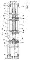
- Fig. 2 is a plan view of the delivery device shown in Fig. 1;
- Fig. 3 is a front view showing the main part of the delivery device shown in Fig. 1;
- Fig. 4 is a sectional view taken along the line IV - IV of Fig. 2;
- Fig. 5 is a view seen from the arrow V of Fig. 2;
- Fig. 6 is a sectional view taken along the line VI - VI of Fig. 5;
- Fig. 7 is a perspective view of an air blowing box to be mounted on the delivery device shown in Fig. 1;
- Fig. 8 is a sectional view showing a state wherein the air blowing box is mounted on a support member;
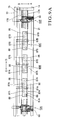
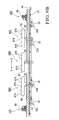
- Figs. 9A and 9B are plan and front views, respectively, of the main part showing a state wherein air blowing boxes are mounted on the delivery device shown in Fig. 1; and
- Fig. 10 is a view for explaining switching between an air intake/exhaust source and a suction unit/discharge unit in the delivery device shown in Fig. 1.
- A delivery device for a sheet-fed offset rotary printing press according to an embodiment of the present invention will be described with reference to Figs. 1 to 10.
- Referring to Fig. 1, a
delivery device 1 for a sheet-fed offset rotary printing press comprises a pair ofdelivery frames 2 which oppose each other at a predetermined gap. The delivery frames 2 axially support a pair ofsprockets 3. A pair ofdelivery chains 4 are looped between the pair ofsprockets 3 of thedelivery frames 2 and a pair of printing unit-side sprockets (not shown). A plurality of sets of gripper units 5 (schematically shown in Fig. 1) comprising grippers and gripper pads line up on each of gripper bars supported between the pair ofdelivery chains 4 at predetermined intervals. After printing, asheet 6 which is gripped by thegripper units 5 and conveyed as thedelivery chains 4 travel is released from thegripper units 5 and drops on the upstream sheet convey direction side of thesprockets 3. - A pile board 7 with four corners suspended by four
elevating chains 8 moves vertically when a motor (not shown) rotates clockwise/counterclockwise. A flat rectangularparallelepiped pallet 9 having a hole where the forks of a fork lift or the like can be inserted is placed on the pile board 7. On the upstream sheet convey direction (a direction of an arrow B) side of the pile board 7, fivesuction units 10A to 10E comprising suction wheels arranged below thesheet 6 under conveyance line up in the widthwise direction (directions of arrows C and D) of thesheet 6 under conveyance, i.e., in a direction perpendicular to the convey direction (directions of an arrow A and the arrow B) of thesheet 6, as shown in Fig. 3. A sheet lay 11 abuts against the leading edge of the droppingsheet 6 to align it. - As shown in Fig. 2, a pair of
subframes subframes driving shaft 16 is rotatably supported between thesubframes subframe 13B and a support stay 18 which is attached between thestays screw shafts screw shafts other subframe 13A with their axial movement being regulated. When the projecting portions of thescrew shafts subframe 13B are manually rotated clockwise and counterclockwise, thesuction units discharge units - The
screw shafts support members 25A, 25B, 25D, and 25E to be movable in the sheet widthwise direction are longitudinal feed inverse helical screws and each have a screw pitch that is larger on the outer side than on the inner side. A support member 25C which is located at the center has no threaded portion and does not move accordingly. Hence, the gap between a discharge unit 80 and suction unit 10 in the widthwise direction of thesheet 6 under conveyance is adjusted in accordance with the size of thesheet 6. - A rotating
shaft 19 is rotatably supported between the pair ofsubframes shaft 19 clockwise/counterclockwise, thesubframes delivery frames 2 throughpinions 20 and racks (not shown) axially mounted on the two ends of the rotatingshaft 19. A sheet lay 21 which abuts against the trailing edge of thesheet 6 dropping onto the pile board 7 to align it has a large number ofair vent holes 21a and is attached to thestay 14 to extend in the directions of the arrows C and D. - As shown in Fig. 3,
blocks 22a each having one end supported by thestay 14 about a correspondingsmall shaft 23 as the swing center swingably supportcorresponding detection pieces 22 which detect the upward movement limit of the pile board 7. When thepallet 9 of the pile board 7 that has moved upward abuts against thedetection pieces 22, thedetection pieces 22 detect thepallet 9 to stop upward movement of the pile board 7. This prevents thepallet 9 from pushing up the suction units 10 or the like. - The
suction units 10A to 10E and the support members 25A to 25E which support them will be described with reference to Figs. 4 to 6. Thesuction units 10A to 10E and the support members 25A to 25E have the same basic structure. Hence, only thesuction unit 10E andsupport member 25E will be described hereinafter, and the remainingsuction units 10A to 10D and support members 25A to 25D will be described when necessary. - As shown in Fig. 4, the
stays like support member 25E to be movable in the widthwise direction (the directions of the arrows C and D) of thesheet 6 under conveyance. Ascrew hole 28 is threadably formed in an inclinedupper mount surface 27 of thesupport member 25E. A flat block-likesupport target member 26E which forms thesuction unit 10E is mounted on the inclinedupper mount surface 27 of thesupport member 25E. Thesupport target member 26E has a vertically extendinginsertion hole 29. Alower surface 30 of thesupport target member 26E is brought into contact with themount surface 27 of thesupport member 25E. After that, a bolt 31 (engaging member) inserted in theinsertion hole 29 is threadably engaged in the screw hole 28 (engaging target portion) to mount thesupport target member 26E on thesupport member 25E. - As shown in Fig. 6, the
support member 25E has a large-diameter throughhole 32 and two small-diameter through holes 33 (one throughhole 33 is not shown). The diameter of the throughhole 32 is larger than the diameter of the drivingshaft 16 and incorporates abearing 34. Asleeve 35 is fitted on the drivingshaft 16. Thesleeve 35 is rotatably supported in the throughhole 32 of thesupport member 25E through thebearing 34. Fastening aset screw 36 allows to rotate thesleeve 35 together with the drivingshaft 16. A ring-like slide member 38A fitted on the drivingshaft 16 and one end face of thesleeve 35 sandwich adriving gear 37. Thedriving gear 37 is mounted on one end face of thesleeve 35 with bolts. - A coming-out
preventive member 40 is mounted on the other end of thesleeve 35 with a set screw. The coming-outpreventive member 40 and astep 35a formed on thesleeve 35 sandwich thesupport member 25E. Thus, when thesupport member 25E moves in the directions of the arrows C and D, thesleeve 35 moves together with thesupport member 25E. Aslide member 38B fitted on the drivingshaft 16 is mounted on the outer surface of the coming-outpreventive member 40. - A substantially cylindrical moving
element 42 having a threadedportion 42a to threadably engage with thescrew shaft 17B is fitted in the throughhole 33 of thesupport member 25E. Aring member 43 axially mounted on one end of the movingelement 42 and astep 42b of the movingelement 42 sandwich thesupport member 25E. When the movingelement 42 moves in the directions of the arrows C and D, thesupport member 25E also moves together with the movingelement 42 in the directions of the arrows C and D. As shown in Fig. 5, a movingelement 44 having the same function as that of the movingelement 42 threadably engages with theother screw shaft 17A. When thescrew shafts support member 25E moves together with thescrew shafts elements support member 25E has anair passage 45 which extends between an upper end opening 45a in its upper surface and alower end opening 45b in its side surface. A hose joint 46 is attached to thelower end opening 45b. - As shown in Fig. 6, a large-
diameter pulley 52 is rotatably supported by ashaft 50, which extends upright on asupport target member 26, through abearing 51. Agear 54 is rotatably supported at the distal end of theshaft 50 through abearing 53. Thegear 54 is mounted on the upper end face of the large-diameter pulley 52 through bolts. Abolt 56 which threadably engages with theshaft 50 through awasher 55 regulates thegear 54 from coming out from the large-diameter pulley 52 andshaft 50. - As shown in Fig. 5, small-diameter pulleys 62 and 63 are rotatably supported by
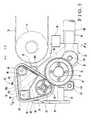
shafts support target member 26, through bearings. Coming-outpreventive members shafts suction belt 66 having a large number ofsuction ports 66a in its outer surface is looped among the small-diameter pulleys 62 and 63 and large-diameter pulley 52 to form a triangle. - As shown in Fig. 5, an
air duct 67 is arranged between the small-diameter pulleys 62 and 63 to oppose the inner side of thesuction belt 66. Theair duct 67 has a U-shaped section such that its upper portion that opposes thesuction belt 66 is open. When suction air from an intake source 101 (to be described later) is supplied to theair duct 67, thatportion 66b of thesuction belt 66 which opposes theair duct 67 forms a suction surface which draws by suction thesheet 6 under conveyance in slidable contact with it. Anair passage 68 is formed under theair duct 67. Theair passage 68 vertically extends through thesupport target member 26 so an upper end opening 68a andlower end opening 68b communicate with each other. The upper end opening 68a of theair passage 68 is connected to acommunication hole 67a formed in the bottom of theair duct 67. - As described above, when the
support target member 26E is mounted on thesupport member 25E, the upper end opening 45a of theair passage 45 comes into contact with thelower end opening 68b of theair passage 68, so theair passage 45 of thesupport member 25E communicates with theair passage 68 of thesupport target member 26E, as shown in Fig. 4. Simultaneously, thedriving gear 37 of thesupport member 25E meshes with thegear 54 of thesupport target member 26E. - As shown in Fig. 5, a
belt 70 which guides thesheet 6 gripped and conveyed by thegripper units 5 is arranged below thedelivery chains 4. Thebelt 70 is looped among a drivenroller 71, a driving roller (not shown), and a tension roller (not shown), and travels at the same speed as that of thedelivery chains 4. - The
air blowing boxes air blowing box 80B (discharge units) will be described with reference to Figs. 7 and 8. As the threeair blowing boxes 80A to 80C have the same basic structure, only theair blowing box 80C will be described, and the remainingair blowing boxes - As shown in Fig. 7, the
air blowing box 80C comprises a base 81 having a trapezoidal section in the directions of the arrows A and B and ahollow body 82 mounted on thebase 81. Thehollow body 82 is formed thin and elongated in the directions of the arrows C and D and has ahollow portion 83 in it. As shown in Fig. 8, thebase 81 has anair passage 84 with an upper end which communicates with thehollow portion 83 of thehollow body 82 through awindow 82a and a lower end which is connected to alower end opening 84a, and aninsertion hole 85 in which the bolt 31 (engaging member) is to be inserted. Alower surface 86 of thebase 81 is brought into contact with themount surface 27 of thesupport member 25E, and thebolt 31 inserted in theinsertion hole 85 is threadably engaged in the screw hole 28 (engaging target portion) of thesupport member 25E, to mount the base 81 on thesupport member 25E. - The
hollow body 82 has fiveair blowing ports 87B and a large number of small-diameter discharge ports 88. Theair blowing ports 87B blow air outwardly (the direction of the arrow D) in the widthwise direction of thesheet 6 under conveyance. Thedischarge ports 88 discharge air upward. A pair of screw holes 89 are formed in the front surface in the direction of the arrow A of thehollow body 82. As shown in Fig. 8, aguide member 90 having an arcuate section is attached to the front surface of thehollow body 82. Theguide member 90 is formed of a thin plate and has abent portion 90a, at its one end, which is formed by bending. Thebent portion 90a is attached to thehollow body 82 withbolts 91 threadably engaging in the screw holes 89 of thehollow body 82. The lower end of theguide member 90 extends downward toward the sheet lay 21. - The
air blowing boxes air blowing box 80A described above in the direction of air discharged from air blowing ports 87. More specifically, as shown in Figs. 9A and 9B, fiveair blowing ports 87A formed in theair blowing box 80A are directed in the direction of the arrow C. The fiveair blowing ports 87B formed in theair blowing box 80C are directed in the direction of the arrow D. Theair blowing box 80B has four air blowing ports, i.e.,air blowing ports air blowing ports 87A close to theair blowing box 80A are directed in the direction of the arrow C, and the remaining twoair blowing ports 87B close to theair blowing box 80C are directed in the direction of the arrow D. - Five
air supply devices 100A to 100E shown in Fig. 10 supply discharge air or suction air to the respective support members 25A to 25E. Theair supply devices 100A to 100E share the oneair intake source 101 which supplies suction air to thesuction units 10A to 10E through the respective support members 25A to 25E. Theair supply devices 100A to 100E also share oneair exhaust source 102 which supplies discharge air to theair blowing boxes 80A to 80C through the support members 25A to 25E. Theair intake source 101 andair exhaust source 102 are shared by theair supply devices 100A to 100E. - The
air intake source 101 andair exhaust source 102 are connected to theair supply devices 100A to 100E through aswitching device 103. Theswitching device 103 comprises anair intake passage 105 which is connected to theintake source 101 through ahose 104, anair blowing passage 107 which is connected to theair exhaust source 102 through ahose 106, anair supply passage 109 which is connected to the hose joint 46 through acommon hose 108, and a switchingvalve 110 which selectively changes over theair passage 109 between theair passages - The switching
valve 110 has anotch 110a with a semilunar section. When thenotch 110a is at the position indicated by an alternate long and two short dashed line in Fig. 10, theair passage 105 andair passage 109 communicate with each other through thenotch 110a. When thenotch 110a is at a position indicated by a solid line where it has been pivoted from the position indicated by the alternate long and two short dashed line by substantially 90°, theair passage 107 andair passage 109 communicate with each other through thenotch 110a. An L-shapedlever 111 is swingably supported at its center about ashaft 112 extending upright from an apparatus fixing portion as the swing center. Amanipulation lever 113 is attached to one end of thelever 111, and one end of aconnection bar 114 is pivotally mounted on the other end of thelever 111. A switchingbar 115 is provided to the switchingvalve 110. The distal end of the switchingbar 115 is pivotally mounted on the other end of theconnection bar 114. - Delivery operation in the delivery device having the above arrangement will be described. First, a case will be described when the convey speed of the sheet delivered by the
suction units 10A to 10E is to be decreased. In this case, thesupport target members 26 are mounted on the mount surfaces 27 of the support members 25A to 25E of all thesuction units 10A to 10E with thebolts 31, as shown in Fig. 4. In this state, the manipulation levers 113 of all theair supply devices 100A to 100E are pivoted counterclockwise, as indicated by the alternate long and two short dashed line in Fig. 10, to allow theair passages 105 andair passages 109 to communicate with each other. - Thus, suction air is supplied to the
air passages 45 of the support members 25A to 25E of all thesuction units 10A to 10E, and to theair passages 68 of support target members 26A to 26D and of thesupport target member 26E which communicate with the correspondingair passages 45. The suction air supplied to theair passages 68 is then supplied to theair ducts 67, so thesheet 6 under conveyance is drawn by suction by the suction surfaces 66b of thesuction belts 66 which oppose theair ducts 67. - Referring to Fig. 6, when the driving
shaft 16 is driven by the motor (not shown) to rotate, thesleeves 35 of the support members 25A to 25E rotate. As thesleeves 35 rotate, the driving gears 37 rotate together with them to rotate thegears 54 of the support target members 26A to 26E meshing with the driving gears 37. Thus, the large-diameter pulleys 52 rotate together with thegears 54, so thesuction belts 66 looped among the corresponding large-diameter pulleys 52 and small-diameter pulleys 62 and 63 travel in the direction of the arrow A at a speed slightly lower than the convey speed of thesheet 6. At this time, the belts 70 (Fig. 5) are driven by motors (not shown) to travel in the direction of the arrow A at substantially the same speed as the traveling speed of thedelivery chains 4. - The
sheet 6 which is released from thegripper units 5 to drop at the convey terminal end of thedelivery device 1 is drawn by suction at its trailing edge by the suction surfaces 66b of the fivesuction belts 66 to be in slidable contact with them. Thus, the traveling speed of thesheet 6 is decreased, so thesheet 6 is stacked on thepallet 9 on the pile board 7. - A case will be described wherein the delivery device is to be shifted from single-sided printing to double-sided and the conditions of the non-image portions are not met. More specifically, assume that the number of non-image portions is limited and non-image portions are not provided at the center in the widthwise direction of the
sheet 6, or even if they are provided, their widths are narrow. In such a case, the threesuction units sheet 6 under conveyance. In this case, theair blowing boxes suction units - First, the
bolts 31 that mount the support target members 26B, 26C, and 26D are loosened, and thesuction units air blowing boxes bolts 31. - In this state, the manipulation levers 113 of the
air supply devices air intake passages 105 andair supply passages 109 to communicate with each other. Thus, suction air is supplied to thesuction units suction belts 66 of thesuction units air passages 107 andair passages 109 to communicate with each other. - Thus, discharge air is supplied to the
air passages 45 of the support members 25B, 25C, and 25D, and to theair passages 84 of theair blowing boxes air passages 45. The discharge air supplied to therespective air passages 84 is discharged from theair blowing ports discharge ports 88 of theair blowing boxes shaft 16 is driven to rotate by the motor (not shown), thesuction belts 66 of thesuction units support members 25A and 25E travel in the direction of the arrow A at a speed slightly lower than the convey speed of thesheet 6. - When delivery operation is performed in this state, air discharged from the
air blowing ports air blowing boxes sheet 6 released from thegripper units 5 to drop at the convey terminal end of thedelivery device 1, forms an air layer that flows outwardly in the widthwise direction of thesheet 6. This air layer conveys thesheet 6 to slightly float from theair blowing boxes sheet 6, and the two ends of thesheet 6 will not disengage from thesuction belts 66 of thesuction units sheet 6 can be decreased sufficiently. As a result, fluttering of thesheet 6 is prevented reliably, and misalignment of the edge of the sheet when stacked can be prevented, and the sheet can be prevented from coming into contact with the brackets of the suction wheels, so its printing surface will not be damaged. - Air is discharged from the
discharge ports 88 of theair blowing boxes sheet 6 under conveyance to float thesheet 6. Thus, middle slack of thesheet 6 can be prevented reliably. The trailing edge of thesheet 6, which is drawn by suction with thesuction units guide members 90. Thus, thesheet 6 is stacked on thepallet 9 smoothly and reliably. - According to this embodiment, the
suction units 10B to 10D andair blowing boxes 80A to 80C can be selectively mounted on the support members 25B to 25D. No discharge units need be provided in advance independently of the suction units, thus simplifying the structure. Both the mounting structures of thesuction units 10B to 10D with respect to the support members 25B to 25D and the mounting structures of thedischarge units 80A to 80C with respect to the support members 25B to 25D employ thebolts 31. Thus, two types of mounting structures are not needed, so the structure can be simplified and the number of components can be decreased. - The
switching device 103 is provided which switches air supply from theair intake source 101/air exhaust source 102 to the suction unit 10/discharge unit 80. Thus, air can be supplied to the suction unit 10 and discharge unit 80 with thecommon hose 108, so the structure can be simplified and the number of components can be decreased. - In this embodiment, the three
discharge units 80A to 80C are provided. Alternatively, the central unit may employ a suction unit, and the pair of units on the two sides may employ discharge units. Of the threedischarge units 80A to 80C, the central unit may employ a discharge unit, and the units on the two sides may employ suction units. The sizes of theair blowing boxes 80A to 80C in the longitudinal direction may be adjustable in accordance with the sheet size. The sheet suffices as far as it is a sheet-type object. - As has been described above, according to the present invention, the suction units and discharge units can be selectively mounted on the support members. No discharge units need be provided in advance independently of the suction units, so the structure can be simplified. Two types of mounting structures are not separately needed for the suction units and discharge units, so the structure can be simplified and the number of components can be decreased. Common pipes allow communication of air between the suction units and discharge units to simplify the structure and decrease the manufacturing cost.
Claims (17)
- A delivery device in a sheet-fed offset rotary printing press, characterized by comprising:a plurality of suction units (10A - 10E) which are arranged above a pile board (7) on an upstream sheet convey direction side below a sheet under conveyance in a widthwise direction of the sheet and which draw by suction the sheet under conveyance in slidable contact therewith;at least one discharge unit (80A - 80C) which replaces one of said plurality of suction units which is other than those on two ends and which discharges air outwardly in the widthwise direction of the sheet under conveyance;at least one support member (25A - 25E) on which said one of said plurality of suction units which is other than those on the two ends and said discharge unit can be mounted selectively; andair switching means (101 - 103) for supplying suction air to said suction unit when said suction unit is mounted on said support member and supplying discharge air to said discharge means when said discharge means is mounted on said support member.
- A device according to claim 1, further comprising a mounting structure (28, 31) with which said one of said plurality of suction units which is other than those on the two ends and said discharge unit are commonly mounted on said support member.
- A device according to claim 2, wherein said mounting structure comprisesan engaging target portion (28) provided to said support member andan engaging member (31) to engage with said engaging target member,said engaging member serving to engage with said engaging target portion to selectively fix said one of said plurality of suction units which is other than those on the two ends and said discharge unit to said support member.
- A device according to claim 3, whereinsaid engaging target portion comprises a screw hole formed in said support member, andsaid engaging member comprises a bolt which is to be threadably engaged in said screw hole through an insertion hole (29, 85) formed in said one of said plurality of suction units which is other than those on the two ends and said discharge unit.
- A device according to claim 1, wherein said air switching means comprisesan air intake source (101) which supplies suction air to said suction unit,an air exhaust source (102) which supplies discharge air to said discharge unit, anda switching valve (110) which switches a first air passage (108) connected to said suction unit/discharge unit between a second air passage (104) connected to said air intake source and a third air passage (106) connected to said air exhaust source.
- A device according to claim 1, wherein said air switching means is provided to correspond to said one of said plurality of suction units which is other than those on the two ends.
- A device according to claim 6, further comprising a manipulation portion (113) which switches said air switching means when said one of said plurality of suction units which is other than those on the two ends is replaced by said discharge unit.
- A device according to claim 1, wherein said discharge unit which is arranged at a portion other than a center in the sheet widthwise direction comprises a plurality of air blowing ports (87A, 87B) which blow air from a center of the sheet under conveyance toward one end in the sheet widthwise direction.
- A device according to claim 1, wherein said discharge unit which is arranged at a center in the sheet widthwise direction comprises a plurality of air blowing ports (87A, 87B) which blow air from a center of the sheet under conveyance toward the two ends in the sheet widthwise direction.
- A device according to claim 1, wherein said discharge unit comprises a plurality of discharge ports (88) which discharge air substantially perpendicularly toward a lower surface of the sheet under conveyance.
- A device according to claim 1, wherein each of said suction units comprises a suction wheel.
- A device according to claim 11, wherein said suction wheel comprises a belt type suction wheel.
- A device according to claim 1, wherein each of said suction units includes a suction surface (66b) which draws by suction the sheet under conveyance to be in slidable contact therewith.
- A device according to claim 1, further comprisinga first driving member (37) which is provided to said support member, anda second driving member (54) which is provided to each of said suction units and is connected to said first driving member,wherein each of said suction unit comprises suction means (66) which is rotatably driven by said second driving member, andwhen said first driving member is driven with each of said suction units being mounted on said support member, said suction means rotates through said second driving member.
- A device according to claim 1, whereinsaid support member comprises a screw hole (28) and first opening (45a) which are common between each of said suction units and said discharge unit,each of said suction units comprises a first insertion port (29) and second opening (68b) which correspond to said screw hole and first opening of said support member, andsaid discharge unit comprises a second insertion port (85) and third opening (84a) which correspond to said screw hole and first opening of said support member.
- A device according to claim 1, whereinsaid support member comprises a plurality of support members arranged in the widthwise direction of the sheet, andsaid plurality of support members selectively support said suction unit/discharge unit.
- A device according to claim 1, further comprising a screw shaft (17A, 17B) which is supported by a frame (13B) and supports said support member to be movable in the widthwise direction of the sheet,
wherein when said screw shaft is operated, said support member is moved in accordance with a sheet size.
Applications Claiming Priority (1)
| Application Number | Priority Date | Filing Date | Title |
|---|---|---|---|
| JP2005260355A JP2007070075A (en) | 2005-09-08 | 2005-09-08 | Paper discharge device in sheet-fed rotary printing press |
Publications (2)
| Publication Number | Publication Date |
|---|---|
| EP1762521A2 true EP1762521A2 (en) | 2007-03-14 |
| EP1762521A3 EP1762521A3 (en) | 2007-03-21 |
Family
ID=37667706
Family Applications (1)
| Application Number | Title | Priority Date | Filing Date |
|---|---|---|---|
| EP06018584A Withdrawn EP1762521A3 (en) | 2005-09-08 | 2006-09-05 | Delivery device in sheet-fed offset rotary printing press |
Country Status (4)
| Country | Link |
|---|---|
| US (1) | US20070052157A1 (en) |
| EP (1) | EP1762521A3 (en) |
| JP (1) | JP2007070075A (en) |
| CN (1) | CN100567109C (en) |
Cited By (3)
| Publication number | Priority date | Publication date | Assignee | Title |
|---|---|---|---|---|
| DE102016206692A1 (en) | 2016-04-20 | 2017-10-26 | Koenig & Bauer Ag | Display of a sheet-processing machine with a sheet brake having brake stations and method for depositing sheets |
| DE102017218404A1 (en) | 2017-10-13 | 2019-04-18 | Koenig & Bauer Ag | Display and method for depositing sheets in the delivery of a sheet-processing machine with a brake stations having sheet brake |
| WO2019081648A1 (en) * | 2017-10-26 | 2019-05-02 | Koenig & Bauer Ag | ARC COMBINING MACHINE WITH AN ELEMENT AND METHOD FOR ADJUSTING A BRAKE STATION OF AN ARC BRAKE IN AN ELEVATOR |
Families Citing this family (2)
| Publication number | Priority date | Publication date | Assignee | Title |
|---|---|---|---|---|
| DE102008025403B4 (en) * | 2008-05-28 | 2020-04-02 | manroland sheetfed GmbH | Boom for a sheet printing machine |
| CN114803588B (en) * | 2022-04-18 | 2024-12-10 | 珠海舒墨科技有限公司 | Transport device with automatic adjustment of track width |
Citations (1)
| Publication number | Priority date | Publication date | Assignee | Title |
|---|---|---|---|---|
| JP2000095409A (en) | 1998-09-18 | 2000-04-04 | Komori Corp | Suction device in sheet-fed rotary printing press |
Family Cites Families (10)
| Publication number | Priority date | Publication date | Assignee | Title |
|---|---|---|---|---|
| JPS6025352B2 (en) * | 1978-03-02 | 1985-06-18 | 住友重機械工業株式会社 | Paper ejection device in double-sided printing machine |
| JPS62205960A (en) * | 1986-03-04 | 1987-09-10 | Komori Printing Mach Co Ltd | Sheet-fed printing machine discharge suction device |
| DE4343713C2 (en) * | 1993-12-21 | 1997-03-27 | Heinen Elektronik Gmbh | Tray for sheets arriving in a row and guided by a transport system |
| JP3238332B2 (en) * | 1996-10-04 | 2001-12-10 | 三菱重工業株式会社 | Sheet guide for sheet-fed printing press |
| DE19758446A1 (en) * | 1997-03-06 | 1998-09-17 | Roland Man Druckmasch | Device for the axial adjustment of bow brakes |
| JP4130501B2 (en) * | 1998-09-16 | 2008-08-06 | 株式会社小森コーポレーション | Suction device in sheet-fed rotary printing press |
| EP0987108B1 (en) * | 1998-09-16 | 2004-03-03 | Komori Corporation | Suction unit in sheet-fed rotary printing press |
| US6871849B2 (en) * | 2000-03-27 | 2005-03-29 | Heidelberger Druckcmaschinen Ag | Delivery for a sheet-processing machine, especially a rotary printing machine |
| DE10239708B4 (en) * | 2002-08-29 | 2013-10-17 | Koenig & Bauer Aktiengesellschaft | Device for guiding and braking sheets in the delivery of a sheet-processing machine, in particular printing press |
| JP4878104B2 (en) * | 2003-07-21 | 2012-02-15 | ハイデルベルガー ドルツクマシーネン アクチエンゲゼルシヤフト | Method for conveying sheets through a printing machine and apparatus for carrying out the method |
-
2005
- 2005-09-08 JP JP2005260355A patent/JP2007070075A/en active Pending
-
2006
- 2006-08-30 US US11/514,021 patent/US20070052157A1/en not_active Abandoned
- 2006-09-05 EP EP06018584A patent/EP1762521A3/en not_active Withdrawn
- 2006-09-07 CN CNB2006101516338A patent/CN100567109C/en not_active Expired - Fee Related
Patent Citations (1)
| Publication number | Priority date | Publication date | Assignee | Title |
|---|---|---|---|---|
| JP2000095409A (en) | 1998-09-18 | 2000-04-04 | Komori Corp | Suction device in sheet-fed rotary printing press |
Cited By (5)
| Publication number | Priority date | Publication date | Assignee | Title |
|---|---|---|---|---|
| DE102016206692A1 (en) | 2016-04-20 | 2017-10-26 | Koenig & Bauer Ag | Display of a sheet-processing machine with a sheet brake having brake stations and method for depositing sheets |
| DE102016206692B4 (en) | 2016-04-20 | 2024-02-22 | Koenig & Bauer Ag | Delivery of a sheet processing machine with a sheet brake having braking stations and method for depositing sheets |
| DE102017218404A1 (en) | 2017-10-13 | 2019-04-18 | Koenig & Bauer Ag | Display and method for depositing sheets in the delivery of a sheet-processing machine with a brake stations having sheet brake |
| DE102017218404B4 (en) | 2017-10-13 | 2020-04-30 | Koenig & Bauer Ag | Delivery and method for depositing sheets in the delivery of a sheet processing machine with a sheet brake having brake stations |
| WO2019081648A1 (en) * | 2017-10-26 | 2019-05-02 | Koenig & Bauer Ag | ARC COMBINING MACHINE WITH AN ELEMENT AND METHOD FOR ADJUSTING A BRAKE STATION OF AN ARC BRAKE IN AN ELEVATOR |
Also Published As
| Publication number | Publication date |
|---|---|
| JP2007070075A (en) | 2007-03-22 |
| CN1927685A (en) | 2007-03-14 |
| EP1762521A3 (en) | 2007-03-21 |
| CN100567109C (en) | 2009-12-09 |
| US20070052157A1 (en) | 2007-03-08 |
Similar Documents
| Publication | Publication Date | Title |
|---|---|---|
| US8353246B2 (en) | Quality inspection apparatus for sheet-shaped matter | |
| US20140047991A1 (en) | Screen printing apparatus and combination printing press including the screen printing apparatus | |
| US5324024A (en) | Paper discharging apparatus | |
| EP2055657A2 (en) | Method for controlling the feed of sheets into a sheet-fed printing press | |
| JP4334073B2 (en) | Sheet paper printing machine | |
| US7611144B2 (en) | Guide device for sheet | |
| US20070052157A1 (en) | Delivery device in sheet-fed offset rotary printing press | |
| EP1764328B1 (en) | Delivery device in sheet-fed offset rotary printing press | |
| EP1614648B1 (en) | Sheet delivery apparatus | |
| US7497437B2 (en) | Sheet guide apparatus | |
| JP3718536B2 (en) | Paper discharge device for sheet-fed printing press | |
| US20050242494A1 (en) | Apparatus for conveying sheets through a printing machine | |
| JP4169223B2 (en) | Suction device in sheet-fed rotary printing press | |
| JP4130501B2 (en) | Suction device in sheet-fed rotary printing press | |
| US6264190B1 (en) | Suction unit in sheet-fed rotary printing press | |
| JP4050398B2 (en) | Suction device in sheet-fed rotary printing press | |
| US20020078843A1 (en) | Method and apparatus for guiding and transferring a sheet in a printing machine | |
| JP2005008374A (en) | Corrugated fiberboard sheet carrying device | |
| DE102008036232A1 (en) | Sheet supplying method for sheet processing machine, involves attaching belt single drive to belt table, and changing shingle distance depending on operating speed of sheet processing machine | |
| EP1740489B1 (en) | Delivery unit for sheet-fed printing or processing machines | |
| JP2001151401A (en) | Printing quality inspection system and printing quality control device of sheet printing machine | |
| JP3553444B2 (en) | Sheet guide device for sheet-fed printing press | |
| JP2004217343A (en) | Sheet discharging device | |
| JP2004155592A (en) | Paper processing equipment | |
| JP2000118773A (en) | Thin plate body conveying device |
Legal Events
| Date | Code | Title | Description |
|---|---|---|---|
| PUAI | Public reference made under article 153(3) epc to a published international application that has entered the european phase |
Free format text: ORIGINAL CODE: 0009012 |
|
| PUAL | Search report despatched |
Free format text: ORIGINAL CODE: 0009013 |
|
| AK | Designated contracting states |
Kind code of ref document: A2 Designated state(s): AT BE BG CH CY CZ DE DK EE ES FI FR GB GR HU IE IS IT LI LT LU LV MC NL PL PT RO SE SI SK TR |
|
| AX | Request for extension of the european patent |
Extension state: AL BA HR MK YU |
|
| AK | Designated contracting states |
Kind code of ref document: A3 Designated state(s): AT BE BG CH CY CZ DE DK EE ES FI FR GB GR HU IE IS IT LI LT LU LV MC NL PL PT RO SE SI SK TR |
|
| AX | Request for extension of the european patent |
Extension state: AL BA HR MK YU |
|
| 17P | Request for examination filed |
Effective date: 20070921 |
|
| AKX | Designation fees paid |
Designated state(s): AT BE BG CH CY CZ DE DK EE ES FI FR GB GR HU IE IS IT LI LT LU LV MC NL PL PT RO SE SI SK TR |
|
| GRAP | Despatch of communication of intention to grant a patent |
Free format text: ORIGINAL CODE: EPIDOSNIGR1 |
|
| STAA | Information on the status of an ep patent application or granted ep patent |
Free format text: STATUS: THE APPLICATION IS DEEMED TO BE WITHDRAWN |
|
| 18D | Application deemed to be withdrawn |
Effective date: 20110401 |