EP1762348A1 - Perforating unit having reduced heat deformation effect and image forming system using the same - Google Patents
Perforating unit having reduced heat deformation effect and image forming system using the same Download PDFInfo
- Publication number
- EP1762348A1 EP1762348A1 EP20060254642 EP06254642A EP1762348A1 EP 1762348 A1 EP1762348 A1 EP 1762348A1 EP 20060254642 EP20060254642 EP 20060254642 EP 06254642 A EP06254642 A EP 06254642A EP 1762348 A1 EP1762348 A1 EP 1762348A1
- Authority
- EP
- European Patent Office
- Prior art keywords
- sheet
- frame
- main face
- perforator
- hole
- Prior art date
- Legal status (The legal status is an assumption and is not a legal conclusion. Google has not performed a legal analysis and makes no representation as to the accuracy of the status listed.)
- Granted
Links
- 230000000694 effects Effects 0.000 title description 2
- 238000005452 bending Methods 0.000 claims abstract description 29
- 238000000034 method Methods 0.000 claims description 11
- 230000008569 process Effects 0.000 claims description 11
- 238000012545 processing Methods 0.000 claims description 8
- 230000032258 transport Effects 0.000 description 83
- 210000000078 claw Anatomy 0.000 description 6
- 238000013461 design Methods 0.000 description 6
- 238000001514 detection method Methods 0.000 description 6
- 230000008859 change Effects 0.000 description 4
- 239000000463 material Substances 0.000 description 4
- 238000000926 separation method Methods 0.000 description 3
- 125000006850 spacer group Chemical group 0.000 description 3
- 230000010485 coping Effects 0.000 description 2
- 238000005520 cutting process Methods 0.000 description 2
- 239000013013 elastic material Substances 0.000 description 2
- 230000002093 peripheral effect Effects 0.000 description 2
- 229920006267 polyester film Polymers 0.000 description 2
- 230000002277 temperature effect Effects 0.000 description 2
- 238000011144 upstream manufacturing Methods 0.000 description 2
- 238000012986 modification Methods 0.000 description 1
- 230000004048 modification Effects 0.000 description 1
- 238000012546 transfer Methods 0.000 description 1
Images




Classifications
-
- B—PERFORMING OPERATIONS; TRANSPORTING
- B26—HAND CUTTING TOOLS; CUTTING; SEVERING
- B26F—PERFORATING; PUNCHING; CUTTING-OUT; STAMPING-OUT; SEVERING BY MEANS OTHER THAN CUTTING
- B26F1/00—Perforating; Punching; Cutting-out; Stamping-out; Apparatus therefor
- B26F1/02—Perforating by punching, e.g. with relatively-reciprocating punch and bed
-
- B—PERFORMING OPERATIONS; TRANSPORTING
- B26—HAND CUTTING TOOLS; CUTTING; SEVERING
- B26F—PERFORATING; PUNCHING; CUTTING-OUT; STAMPING-OUT; SEVERING BY MEANS OTHER THAN CUTTING
- B26F1/00—Perforating; Punching; Cutting-out; Stamping-out; Apparatus therefor
- B26F1/02—Perforating by punching, e.g. with relatively-reciprocating punch and bed
- B26F1/14—Punching tools; Punching dies
-
- G—PHYSICS
- G03—PHOTOGRAPHY; CINEMATOGRAPHY; ANALOGOUS TECHNIQUES USING WAVES OTHER THAN OPTICAL WAVES; ELECTROGRAPHY; HOLOGRAPHY
- G03G—ELECTROGRAPHY; ELECTROPHOTOGRAPHY; MAGNETOGRAPHY
- G03G15/00—Apparatus for electrographic processes using a charge pattern
- G03G15/65—Apparatus which relate to the handling of copy material
- G03G15/6582—Special processing for irreversibly adding or changing the sheet copy material characteristics or its appearance, e.g. stamping, annotation printing, punching
-
- G—PHYSICS
- G03—PHOTOGRAPHY; CINEMATOGRAPHY; ANALOGOUS TECHNIQUES USING WAVES OTHER THAN OPTICAL WAVES; ELECTROGRAPHY; HOLOGRAPHY
- G03G—ELECTROGRAPHY; ELECTROPHOTOGRAPHY; MAGNETOGRAPHY
- G03G2215/00—Apparatus for electrophotographic processes
- G03G2215/00362—Apparatus for electrophotographic processes relating to the copy medium handling
- G03G2215/00789—Adding properties or qualities to the copy medium
- G03G2215/00818—Punch device
-
- Y—GENERAL TAGGING OF NEW TECHNOLOGICAL DEVELOPMENTS; GENERAL TAGGING OF CROSS-SECTIONAL TECHNOLOGIES SPANNING OVER SEVERAL SECTIONS OF THE IPC; TECHNICAL SUBJECTS COVERED BY FORMER USPC CROSS-REFERENCE ART COLLECTIONS [XRACs] AND DIGESTS
- Y10—TECHNICAL SUBJECTS COVERED BY FORMER USPC
- Y10T—TECHNICAL SUBJECTS COVERED BY FORMER US CLASSIFICATION
- Y10T83/00—Cutting
- Y10T83/283—With means to control or modify temperature of apparatus or work
- Y10T83/293—Of tool
-
- Y—GENERAL TAGGING OF NEW TECHNOLOGICAL DEVELOPMENTS; GENERAL TAGGING OF CROSS-SECTIONAL TECHNOLOGIES SPANNING OVER SEVERAL SECTIONS OF THE IPC; TECHNICAL SUBJECTS COVERED BY FORMER USPC CROSS-REFERENCE ART COLLECTIONS [XRACs] AND DIGESTS
- Y10—TECHNICAL SUBJECTS COVERED BY FORMER USPC
- Y10T—TECHNICAL SUBJECTS COVERED BY FORMER US CLASSIFICATION
- Y10T83/00—Cutting
- Y10T83/727—With means to guide moving work
- Y10T83/744—Plural guide elements
- Y10T83/745—Opposed
-
- Y—GENERAL TAGGING OF NEW TECHNOLOGICAL DEVELOPMENTS; GENERAL TAGGING OF CROSS-SECTIONAL TECHNOLOGIES SPANNING OVER SEVERAL SECTIONS OF THE IPC; TECHNICAL SUBJECTS COVERED BY FORMER USPC CROSS-REFERENCE ART COLLECTIONS [XRACs] AND DIGESTS
- Y10—TECHNICAL SUBJECTS COVERED BY FORMER USPC
- Y10T—TECHNICAL SUBJECTS COVERED BY FORMER US CLASSIFICATION
- Y10T83/00—Cutting
- Y10T83/929—Tool or tool with support
-
- Y—GENERAL TAGGING OF NEW TECHNOLOGICAL DEVELOPMENTS; GENERAL TAGGING OF CROSS-SECTIONAL TECHNOLOGIES SPANNING OVER SEVERAL SECTIONS OF THE IPC; TECHNICAL SUBJECTS COVERED BY FORMER USPC CROSS-REFERENCE ART COLLECTIONS [XRACs] AND DIGESTS
- Y10—TECHNICAL SUBJECTS COVERED BY FORMER USPC
- Y10T—TECHNICAL SUBJECTS COVERED BY FORMER US CLASSIFICATION
- Y10T83/00—Cutting
- Y10T83/929—Tool or tool with support
- Y10T83/9411—Cutting couple type
- Y10T83/9423—Punching tool
- Y10T83/9428—Shear-type male tool
Definitions
- the present disclosure generally relates to an image forming system having an image forming unit and finishing unit, and more particularly to a finishing unit, which processes a sheet transported from an image forming unit.
- An image forming apparatus such as printer, copier, facsimile, and MFP (multi-functional peripherals) may be attached with a finishing unit, to which a sheet having an image thereon is ejected from the image forming apparatus.
- a finishing unit to which a sheet having an image thereon is ejected from the image forming apparatus.
- the finishing unit may include a perforator to perforate a hole on the sheet ejected from the image forming apparatus.
- the perforator includes a reciprocal type unit having a die frame, a guide frame, and a blade, for example.
- the die frame includes a die hole, and is placed under a transport path of sheet.
- the guide frame includes a guide hole, and is placed over the transport path of sheet.
- the die hole and guide hole are aligned in a same axial direction so that the blade can be moved in a reciprocal direction through the guide hole and die hole.
- the blade is moved in the reciprocal direction through the guide hole and die hole to perforate a hole on the sheet, transported between the die frame and guide frame.
- the blade may be supported by the guide frame with a given allowance such as 10 micrometers, for example.
- the blade and die frame are designed in a manner so that the blade and die hole have a given amount of clearance between the blade and die hole such as 10 to 20 micrometers, for example.
- Such perforator may be affected by heat generated in the image forming unit, wherein the heat may be generated when the image forming unit conducts an image transfer process, for example.
- Such heat may affect a plurality of parts in the perforator, and may cause a temperature variation between the plurality of parts in the perforator.
- a sheet is temporarily stopped and then pressed to the die frame to perforate a hole on the sheet with a reciprocal movement of the blade through the die hole of the die frame, wherein the sheet may have some heat energy received during image forming process in the image forming unit.
- the die frame may become into a relatively higher temperature condition compared to the guide frame.
- the die frame and guide frame may be firmly fixed with each other by a rivet or the like to maintain a preciseness of perforation.
- one of the die frame and guide frame may be deflected.
- Such deflection may be observed as an elongation of the die frame due to a temperature increase of the die frame. Such elongation may occur to the die frame because the die frame and guide frame are fixed firmly as above-mentioned.
- Such deflection may occur in either one of two directions depending on a shape of the guide frame and die frame.
- One direction is a parallel direction with respect to the transport direction of sheet, and another direction is a vertical direction with respect to the transport direction of sheet.
- the guide hole and die hole may be deviated from the aligned condition.
- the blade may not pass through the die hole smoothly, the blade may become into an overloaded condition, by which the image forming system may stop the movement of blade, and then an operation of the image forming system may be stopped.
- the present disclosure relates to a perforator for use with a sheet, comprising:
- the present disclosure also relates to a perforator for use with a sheet, comprising:
- the present invention further provides a finishing unit for use with an image forming unit for forming an image on a sheet, the finishing unit comprising a perforator according to any preceding claim and a processing unit configured to conduct a processing operation for the sheet other than perforating the sheet.
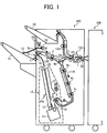
- FIG. 1 is a schematic configuration of an image forming system including an image forming apparatus 100 and finishing unit 200.
- the image forming apparatus 100 includes a copier, for example.
- the finishing unit 200 attached next to the image forming apparatus 100, includes a perforator, for example.
- the image forming apparatus 100 includes an image forming unit and a fixing unit, wherein the image forming unit forms a toner image on a sheet, and the fixing unit fixes the toner image on the sheet, and then the sheet is transported to the finishing unit 200 from the fixing unit.
- the finishing unit 200 includes a perforator 121 to perforate a hole on the sheet transported from the image forming apparatus 100, for example.
- the finishing unit 200 may conduct a plurality of processing operations to the sheet including perforation process, and ejects the sheet outside of the finishing unit 200 after conducting processing operations to the sheet.
- the image forming apparatus 100 transports a sheet to the finishing unit 200 via a sheet transport route 2R.
- the sheet transport route 2R is surrounded by an entrance sensor 36, the perforator 121 (e.g., reciprocal type unit), an entrance roller 1, and separation claws 8a and 8b, for example.
- the perforator 121 e.g., reciprocal type unit
- the entrance roller 1 e.g., an entrance roller 1
- separation claws 8a and 8b for example.
- the entrance sensor 36 detects a front edge and rear edge of sheet transported from the image forming apparatus 100.
- Each of the separation claws 8a and 8b is controlled by a solenoid (not shown) and spring (not shown).
- the sheet transported from the image forming apparatus 100 can be transported to a first sheet tray 12, a second sheet tray 14, or to a stapler 11, as required.
- a sort/stack route 12R extends from the sheet transport route 2R to the first sheet tray 12.
- the sort/stack route 12R includes a transport roller 2, a sheet ejection sensor 38, an ejection roller 3, an adjust roller 7, a sheet detection lever 13, and sheet detection sensors 32 and 33, for example.
- the sheet ejection sensor 38 detects a sheet.
- the ejection roller 3 includes a drive roller 3a and a driven roller 3b.
- the adjust roller 7 adjusts a lateral edge of sheets to one side on the first sheet tray 12.
- the sheet detection lever 13 moves in a vertical direction depending on a number of sheets stacked on the first sheet tray 12.
- the sheet detection sensors 32 and 33 detect a height of sheets stacked on the first sheet tray 12.
- the driven roller 3b is normally biased and contacted to the drive roller 3a with a self-weight of the driven roller 3b or spring force, for example.
- Sheets or stapled sheets can be ejected to the first sheet tray 12 through a nip between the drive roller 3a and driven roller 3b.
- a transport route 14R extends from the sheet transport route 2R to the second sheet tray 14, and a plurality of transport rollers are disposed along the transport route 14R.
- the second sheet tray 14 stacks sheets printed by facsimile or printer function of the image forming apparatus 100, wherein such facsimile or printer function may be conducted by interrupting another function such as copying.
- a staple transport route 11R extends from the sheet transport route 2R to the stapler 11 in a staple unit 15, and a plurality of transport rollers 4a, 4b, and 4c are disposed along the staple transport route 11R.
- the staple unit 15 includes a sheet ejection sensor (not shown), and a sheet feed roller 6 having a brush, for example.
- the transport rollers 4a, 4b, and 4c can be driven by a transport motor (not shown).
- the staple unit 15 includes a staple tray (not shown) and the stapler 11, wherein the staple tray is used to support parts used for staple unit 15, and the stapler 11 is provided under the staple tray.
- the staple tray is attached with a jogger fence 9, a return roller 5, and an ejection belt 10.
- the jogger fence 9 collates sheets.
- the ejection belt 10 is provided next to the jogger fence 9 to eject stapled sheets.
- the ejection belt 10 includes an ejection claw 10a fixed on the ejection belt 10, wherein the ejection claw 10a can support a rear edge of stapled sheets stapled by the stapler 11.
- the jogger fence 9 can be moved in a width direction of the sheet by a jogger motor (not shown) and jogger belt (not shown).
- the return roller 5 can be driven with a solenoid (not shown), and can contact a surface of sheet.
- a rear fence 19 is disposed under the jogger fence 9, wherein the rear fence 19 can be abutted to a rear edge of sheets.
- the stapler 11 can be driven by a stapler motor (not shown) and a stapler belt (not shown), and can be moved in a front and rear direction of the finishing unit 200.
- the rear edge of the stapled sheets, stapled by the stapler 11, is supported by the ejection claw 10a fixed on the ejection belt 10.
- the stapled sheets are ejected to the first sheet tray 12 with a guide effect of the guide plate 20.
- the first sheet tray 12 can be hanged by a lift belt (not shown), for example, wherein the lift belt can be driven by a lift motor (not shown) and a gear system having a worm gear and a timing belt.
- the lift belt can be moved in a vertical direction (i.e., upward or downward direction) by adjusting a rotation direction of the lift motor.
- the first sheet tray 12 can be moved in a horizontal direction with a shift motor (not shown), as required.
- the sheet detection lever 13 and sheet detection sensors 32 and 33 are used to detect a home position and height of the first sheet tray 12.
- a limit sensor (not shown) detects such condition.
- a limit switch (not shown) becomes an OFF state to stop a rotation of the lift motor, by which a mechanical damage caused by overrunning of the first sheet tray 12 can be prevented.
- FIG. 2 is a schematic cross sectional view of the perforator 121 according to an example embodiment.
- FIG. 3 is a schematic view of the perforator 121 when viewed from a sheet entrance side.
- FIG. 2 corresponds to a cross-section view cut at line A-A in FIG. 3.
- the perforator 121 may include a blade 301, a guide frame 310, and a die frame 312.
- the perforator 121 may also include a motor 302, a belt 303, a drive pulley 304, a shaft 305, a home position sensor 306, a cam 307, a holder 308, a hopper 309, a heat insulating member 314, a spacer 315, a rivet 316, and a transport guide member 317, for example.
- the blade 301 can perforate a hole on a sheet P when the blade 301 moves in a vertical direction with respect to a transport direction of sheet P.
- the blade 301 has an edge formed in wedge shape so that the blade 301 can easily perforate a hole on the sheet P.
- the motor 302 can drive the drive pulley 304 via the belt 303.
- the motor 302 can transmit a driving force to the drive pulley 304 because the belt 303 connects the motor 302 and drive pulley 304.
- the drive pulley 304 can drive the blade 301 in a vertical direction with respect to a transport direction of sheet P via the shaft 305, cam 307, and holder 308.
- the home position sensor 306 detects an initial position of blade 301 in the perforator 121.
- the holder 308 can regulate a position of the blade 301.
- the blade 301 can be moved in an upward and downward direction when the cam 307 makes a given rotational movement around the shaft 305 with a movement of the drive pulley 304.
- the hopper 309 recovers cuttings of the sheet P, which are produced when the blade 301 perforates a hole on the sheet P.
- the die frame 312 may be provided under the transport path of sheet P, and guides the sheet P from the downward direction.
- the die frame 312 includes a first main face 312a and a first inclined corner 312b, for example.
- the first inclined corner 312b is extended along the first main face 312a (see FIG. 6A).
- the die frame 312 also includes a die hole 313 on the first main face 312a, through which the blade 301 moves in the vertical direction with respect to the transport direction of the sheet P.
- the first main face 312a can be used to guide the sheet P from the downward direction, and the first inclined corner 312b is inclined with respect to the transport direction of sheet P as shown in FIG. 2.
- the guide frame 310 may be provided over an upper area of the transport path of sheet P, and guides the sheet P from the upward direction.
- the guide frame 310 includes a second main face 310a and a second inclined corner 310b, for example.
- the second inclined corner 310b is extended along the second main face 310a (see FIG. 6A).
- the guide frame 310 also includes a guide hole 311 on the second main face 310a, through which the blade 301 moves in the vertical direction with respect to the transport direction of the sheet P.
- the second main face 310a can be used to guide the sheet P from the upward direction, and the second inclined corner 310b is inclined with respect to the transport direction of the sheet P as shown in FIG. 2.
- the sheet P can be easily guided between the first main face 312a and second main face 310a.
- the die frame 312 may include a cut-off area C apart from the first main face 312a and first inclined corner 312b, which face the transport direction of sheet P as shown in FIGs. 2 and 3. Such cut-off area C will be explained later with FIG. 6.
- the cut-off area C may be cut in a rectangular shape from a face, which has no specific function in the die frame 312, as shown in FIG. 6.
- cut-off area C can be cut in any shape depending on an entire shape of the die frame 312, and considering other parts around the die frame 312.
- the heat insulating member 314 can be made of material having lower heat conductivity compared to a material for the die frame 312.
- the heat insulating member 314 may be disposed along the first inclined corner 312b.
- the sheet P may absorb some heat energy when a fixing process is conducted in the image forming apparatus 100. Such heated sheet P is transported to the perforator 121 through the first inclined corner 312b, and then the sheet P passes through a transport path in the perforator 121.
- the heat insulating member 314 may contact the sheet P when the sheet P passes through the first inclined corner 312b, by which the heat insulating member 314 may suppress heat conduction from the heated sheet P to the first inclined corner 312b.
- the heat insulating member 314 may suppress heat conduction from the heated sheet P to the die frame 312.
- the heat insulating member 314 includes an edge portion 314a, which protrudes from the first main face 312a with some length.
- the die frame 312 and guide frame 310 have a given space between the first main face 312a and second main face 310a.
- space may be approximately 2 mm.
- edge portion 314a may protrude from the first main face 312a within a range of 0.5 mm to 1 mm, for example, such edge portion 314a may not hinder a transportation of the sheet P.
- the heat insulating member 314 is preferably made of elastic material such as polyester film to reduce hindering of transportation of sheet P by the heat insulating member 314.
- the spacer 315 is disposed at each lateral side of the transport path in the perforator 121.
- the spacer 315 is used to effectively secure the given space between the guide frame 310 and die frame 312.
- the rivet 316 is used to firmly fix the guide frame 310 and die frame 312 each other to maintain a positional relationship of the guide frame 310 and die frame 312.
- the perforator 121 may conduct sheet perforation precisely.
- the transport guide member 317 is provided in an upstream of transport direction of sheet P with respect to the guide frame 310 and die frame 312, and guides the sheet P to the given space between the guide frame 310 and die frame 312.
- the transport guide member 317 includes an upper guide member 318 and a lower guide member 319, wherein the upper guide member 318 guides the sheet P from the upward direction and the lower guide member 319 guides the sheet P from the downward direction.
- the upper guide member 318 includes an upper guide face 318a, which guides the sheet P from the upward direction.
- the lower guide member 319 includes a lower guide face 319a, which guides the sheet P from the downward direction.
- the upper guide face 318a of the upper guide member 318 may be positioned below the second main face 310a of the guide frame 310 (refer to a dotted line M in FIG. 2), and the lower guide face 319a of the lower guide member 319 may be positioned below the first main face 312a of the die frame 312 (refer to a dotted line L in FIG. 2).
- the sheet P may more likely to contact with the die frame 312 compared to the guide frame 310 in a configuration shown in FIG. 2.
- the die frame 312 may be more affected by the heated sheet P compared to the guide frame 310.
- a design work for coping with temperature change in the perforator 121 may be mainly considered for the die frame 312, but not for the guide frame 310, by which the design work can be conducted with fewer amount of time or steps. Accordingly, a total amount of design works can be reduced.
- FIG. 4 shows schematic sequential views for explaining a process of perforation on the sheet P by the perforator 121.
- a process of perforation on the sheet P by the perforator 121 is explained.
- the upper guide face 318a of the upper guide member 318 may be positioned below the second main face 310a of the guide frame 310 (refer to a dotted line M in FIG. 2), and the lower guide face 319a of the lower guide member 319 may be positioned below the first main face 312a of the die frame 312 (refer to a dotted line L in FIG. 2).
- the sheet P may be transported from the transport guide member 317 to the first inclined corner 312b of the die frame 312.
- the heat insulating member 314 overlays the first inclined corner 312b as above-mentioned, therefore, the sheet P may contact with the heat insulating member 314.
- the sheet P may not contact the first inclined corner 312b directly, by which the heat insulating member 314 may suppress heat conduction from the sheet P to the first inclined corner 312b.
- edge portion 314a may effectively prevent a contact of the sheet P to the die frame 312 as below explained.
- the sheet P in a transport path may not be strictly parallel to the transport path, but the sheet P in the transport path may be somehow curled in a downward direction, for example.
- the curled portion of sheet P may contact the first main face 312a when the sheet P enters the perforator 121, by which the sheet P may transmit heat to the die frame 312.
- the curled portion of the sheet P may not contact the first main face 312a at an entrance of the die frame 312, by which a temperature increase of the die frame 312 may be suppressed.
- the sheet P transported from the image forming apparatus 100 with such manner is stopped temporarily in the perforator 121 to receive a perforation operation.
- the sheet P is perforated by moving the blade 301 in an upward/downward direction with the motor 302, and passing the blade 301 through the guide hole 311 and die hole 313.
- the motor 302 drives the drive pulley 304 and shaft 305 via the belt 303.
- the home position sensor 306 detects a rotation of the drive pulley 304 and shaft 305.
- a control unit transmits a signal to the motor 302 to stop the rotation of the drive pulley 304 and shaft 305 after rotating the shaft 305 for one rotation.
- the cam 307 rotates with a rotation of the shaft 305 and moves the holder 308 in an upward/downward direction, wherein the shaft 305 is eccentrically engaged to the cam 307 as shown in FIG. 2 and 3.
- FIG. 4(a) shows an initial position of the holder 308 in the perforator 121, in which the shaft 305 contacts the holder 308.
- the cam 307 rotates in a clockwise direction with a rotation of the shaft 305 to move the blade 301 in a downward direction.
- the cam 307 further rotates, and the shaft 305 contacts the holder 308 at an upper portion of the holder 308. At this position, the blade 301 is moved to the lowest position to perforate the sheet P.
- the cam 307 further rotates in a clockwise direction and moves the blade 301 in an upward direction.
- the blade 301 moves in an upward/downward direction, and then the blade 301 passes through the guide hole 311 of the guide frame 310 and the die hole 313 of the die frame 312.
- the finishing unit 200 may conduct another processing operation to the sheet P, as required.
- the hopper 309 recovers cuttings of perforated sheet cut from the sheet P.
- the die frame 312 can include a cut-off area C on a first side face perpendicular to the first main face 312a, which will be explained later with FIGs. 6A and 6B.
- the die frame 312 may have a smaller face area in the first side face perpendicular to the first main face 312a of the die frame 312.
- a bending strength of the first main face 312a in a vertical direction with respect to the transport path of sheet P may become smaller than a bending strength of the first main face 312a in a parallel direction with respect to the transport path of sheet P.
- FIGs. 5A and 5B are perspective views of the guide frame 310 and die frame 312, in which the die frame 312 has no cut-off area.
- FIG. 6A and 6B are perspective views of the guide frame 310 and die frame 312, in which the die frame 312 has a cut-off area C.
- the sheet P has not yet transmitted heat to the die frame 312.
- the die frame 312 is in a lower temperature condition, and thereby the die frame 312 may not deflect.
- the guide hole 311 and die hole 313 are aligned on a same axis direction, by which the blade 301 can pass through the guide hole 311 and die hole 313 smoothly.
- the die frame 312 may deflect significantly compared to the guide frame 310.
- a deflection caused by such heated sheet P may be observed as warping of plane having a smaller bending strength in the die frame 312.
- a bending strength of the first main face 312a in a parallel direction with respect to the transport path of sheet P may become smaller than a bending strength of the first main face 312a in a vertical direction with respect to the transport path of sheet P.
- the die frame 312 having no cut-off area may warp in a parallel direction with respect to the transport path of sheet P.
- the die hole 313 may deviate from an original position, and the guide hole 311 and die hole 313 may not align on the same axis direction, which is indicated by a positional deviation S1 in FIG. 5B.
- the blade 301 may not pass through the guide hole 311 and die hole 313 smoothly or the blade 301 cannot pass through the guide hole 311 and die hole 313.
- FIG. 6A shows the die frame 312 in lower temperature condition.
- the die frame 312 can include the cut-off area C on a first side face 312c perpendicular to the first main face 312a as shown in FIG. 6A.
- the die frame 312 may have a smaller face area in the first side face 312c, which is perpendicular to the first main face 312a.
- a bending strength of the first main face 312a in a vertical direction with respect to the transport path of sheet P may become smaller than a bending strength of the first main face 312a in a parallel direction with respect to the transport path of sheet P.
- the die frame 312 may warp in a vertical direction with respect to the transport path of sheet P.
- the die hole 313 may not substantially deviate from the original position, and the guide hole 311 and die hole 313 may still align on the same axis direction substantially as shown in FIG. 6B. In a condition shown in FIG. 6B, the blade 301 may pass through the guide hole 311 and die hole 313 smoothly.
- a condition shown in FIG. 6B may reduce a temperature effect to the die frame 312, and may suppress the deflection of the first main face 312a in a parallel direction with respect to the transport path of sheet P, which may affect the alignment of the guide hole 311 and die hole 313. Accordingly, an alignment deviation of the guide hole 311 and die hole 313 may be suppressed.
- the heat insulating member 314 may be overlaid on the die frame 312 as above-mentioned, by which the sheet P may contact the heat insulating member 314 before the sheet P enters a sheet transport path in the perforator 121.
- a contact time of the sheet P and die frame 312 may be reduced when the sheet P enters and passes through the perforator 121, by which a temperature increase of die frame 312 may be suppressed.
- the heat insulating member 314 may suppress a temperature change of the die frame 312, by which the deflection of the first main face 312a in a vertical direction with respect to the transport path of sheet P may be suppressed.
- the alignment deviation of the guide hole 311 and die hole 313 may be suppressed.
- cut-off area C and heat insulating member 314 are provided for the die frame 312 in the above explained example embodiment, the cut-off area C and heat insulating member 314 may be provided for the guide frame 310 as below explained with reference to FIGs. 7 and 8.
- FIG. 7 is a schematic cross sectional view of the perforator 121 according to another example embodiment.
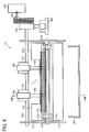
- FIG. 8 is a schematic view of the perforator 121 according to another example embodiment when viewed from a sheet entrance side.
- FIG. 7 corresponds to a cross-section view cut at line A-A in FIG. 8.
- the perforator 121 shown in FIGs. 7 and 8 may employ similar components shown in FIGs. 2 and 3, but some of them may have different arrangement or shape as below explained.
- the guide frame 310 may include a cut-off area C except the second main face 310a and second inclined corner 310b, which face the transport direction of sheet P as shown in FIGs. 7 and 8. Such cut-off area C will be explained later with FIG. 10.
- the cut-off area C may be cut in a rectangular shape from a face, which has no specific function in the guide frame 310, as shown in FIG. 10.
- cut-off area C can be cut in any shape depending on an entire shape of the guide frame 310, and considering other parts around the guide frame 310.
- the die frame 312 has no cut-off area C in another example embodiment shown in FIGs. 7 and 8.
- the heat insulating member 314 can be made of material having lower heat conductivity compared to a material for the guide frame 310.
- the heat insulating member 314 may be disposed along the second inclined corner 310b, which is different from a configuration in FIGs. 2 and 3.
- the sheet P may absorb some heat energy when a fixing process is conducted in the image forming apparatus 100. Such heated sheet P is transported to the perforator 121 through the second inclined corner 310b, and then the sheet P passes through a transport path in the perforator 121.
- the heat insulating member 314 may contact the sheet P when the sheet P passes through the second inclined corner 310b, by which the heat insulating member 314 may suppress heat conduction from the heated sheet P to the second inclined corner 310b.
- the heats insulating member 314 may suppress heat conduction from the heated sheet P to the guide frame 310.
- the heat insulating member 314 includes the edge portion 314a, which protrudes from the second main face 310a with some length.
- the die frame 312 and guide frame 310 have the given space between the first main face 312a and second main face 310a.
- space may be approximately 2 mm.
- edge portion 314a may protrude from the second main face 310a within a range of 0.5 mm to 1 mm, for example, such edge portion 314a may not hinder a. transportation of the sheet P.
- the heat insulating member 314 is preferably made of elastic material such as polyester film to reduce hindering of transportation of sheet P by the heat insulating member 314.
- the transport guide member 317 is provided in an upstream of transport direction of sheet P with respect to the guide frame 310 and die frame 312, and guides the sheet P to the given space between the guide frame 310 and die frame 312.
- the transport guide member 317 includes the upper guide member 318 and the lower guide member 319, wherein the upper guide member 318 guides the sheet P from the upward direction and the lower guide member 319 guides the sheet P from the downward direction.
- the upper guide member 318 includes the upper guide face 318a, which guides the sheet P from the upward direction.
- the lower guide member 319 includes the lower guide face 319a, which guides the sheet P from the downward direction.
- the upper guide face 318a of the upper guide member 318 may be positioned above the second main face 310a of the guide frame 310 (refer to a dotted line O in FIG. 7), and the lower guide face 319a of the lower guide member 319 may be positioned above the first main face 312a of the die frame 312 (refer to a dotted line N in FIG. 7).
- the sheet P may more likely to contact with the guide frame 310 compared to the die frame 312.
- the guide frame 310 may be more affected by the heated sheet P compared to the die frame 312.
- a design work for coping with the temperature change in the perforator 121 may be mainly considered for the guide frame 310, but not for the die frame 312, by which the design work can be conducted with fewer amount of time or steps. Accordingly, a total amount of design works can be reduced.
- the perforator 121 shown in FIG. 7 can perforate a hole on the sheet P in a similar manner explained with FIG. 4. However, the sheet P is transported in a different manner in the perforator 121 as below explained.
- the upper guide face 318a of the upper guide member 318 may be positioned above the second main face 310a of the guide frame 310 (refer to a dotted line O in FIG. 7), and the lower guide face 319a of the lower guide member 319 may be positioned above the first main face 312a of the die frame 312 (refer to a dotted line N in FIG. 7).
- the sheet P may be transported from the transport guide member 317 to the second inclined corner 310b of the guide frame 310.
- the heat insulating member 314 overlays the second inclined corner 310b as above-mentioned, therefore, the sheet P may contact with the heat insulating member 314.
- the sheet P may not contact the second inclined corner 310b directly, by which the heat insulating member 314 may suppress heat conduction from the sheet P to the second inclined corner 310b.
- edge portion 314a may effectively prevent a contact of the sheet P to the guide frame 310 as below explained.
- the sheet P in a transport path may not be strictly parallel to the transport path, but the sheet P in the transport path may be somehow curled in an upward direction, for example.
- the curled portion of sheet P may contact the second main face 310a when the sheet P enters the perforator 121, by which the sheet P may transmit heat to the guide frame 310.
- the curled portion of the sheet P may not contact the second main face 310a at an entrance of the guide frame 310, by which a temperature increase of the guide frame 310 may be suppressed.
- the sheet P transported from the image forming apparatus 100 with such manner is stopped temporarily in the perforator 121 to receive a perforation operation.
- the guide frame 310 can include a cut-off area C on a second side face perpendicular to the second main face 310a, which will be explained later with FIGs. 10A and 10B.
- the guide frame 310 may have a smaller face area in the second side face perpendicular to the second main face 310a.
- a bending strength of the second main face 310a in a vertical direction with respect to the transport path of sheet P may become smaller than a bending strength of the second main face 310a in a parallel direction with respect to the transport path of sheet P.
- FIGs. 9A and 9B are perspective views of the guide frame 310 and die frame 312, in which the guide frame 310 has no cut-off area.
- FIG. 10A and 10B are perspective views of the guide frame 310 and die frame 312, in which the guide frame 310 has a cut-off area C.
- the sheet P has not yet transmitted heat to the guide frame 310.
- the guide frame 310 is in a lower temperature condition, and thereby the guide frame 310 may not deflect.
- the guide hole 311 and die hole 313 are aligned on a same axis direction, by which the blade 301 can pass through the guide hole 311 and die hole 313 smoothly.
- the guide frame 310 may deflect significantly compared to the die frame 312.
- a deflection caused by such heated sheet P may be observed as warping of plane having a smaller bending strength in the guide frame 310.
- a bending strength of the second main face 310a in a parallel direction with respect to the transport path of sheet P may become smaller than a bending strength of the second main face 310a in a vertical direction with respect to the transport path of sheet P.
- the guide frame 310 having no cut-off area may warp in a parallel direction with respect to the transport path of sheet P.
- the guide hole 311 may deviate from an original position, and the guide hole 311 and die hole 313 may not align on the same axis direction, which is indicated by a positional deviation S2 in FIG. 9B.
- the blade 301 may not pass through the guide hole 311 and die hole 313 smoothly or the blade 301 cannot pass through the guide hole 311 and die hole 313.
- a configuration having a cut-off area C shown in FIG. 10 is employed for the guide frame 310.
- FIG. 10A shows the guide frame 310 in lower temperature condition.
- the guide frame 310 can include a cut-off area C on a second side face 310c perpendicular to the second main face 310a as shown in FIG. 10A.
- the guide frame 310 may have a smaller face area in the second side face 310c, which is perpendicular to the second main face 310a of the guide frame 310.
- a bending strength of the second main face 310a in a vertical direction with respect to the transport path of sheet P may become smaller than a bending strength of the second main face 310a in a parallel direction with respect to the transport path of sheet P.
- the guide frame 310 may warp in a vertical direction with respect to the transport path of sheet P.
- the guide hole 311 may not substantially deviate from the original position, and the guide hole 311 and die hole 313 may still align on the same axis direction substantially as shown in FIG. 10B.
- the blade 301 may pass through the guide hole 311 and die hole 313 smoothly.
- a condition shown in FIG. 10B may reduce a temperature effect to the guide frame 310, and may suppress the deflection of the second main face 310a in a parallel direction with respect to the transport path of sheet P, which may affect the alignment of the guide hole 311 and die hole 313. Accordingly, an alignment deviation of the guide hole 311 and die hole 313 may be suppressed.
- the heat insulating member 314 may be overlaid on the guide frame 310 as above-mentioned, by which the sheet P may contact the heat insulating member 314 before the sheet P enters a sheet transport path in the perforator 121.
- a contact time of the sheet P and guide frame 310 may be reduced when the sheet P enters and passes through the perforator 121, by which a temperature increase of guide frame 310 may be suppressed.
- the heat insulating member 314 may suppress a temperature change of the guide frame 310, by which the deflection of the second main face 310a in a vertical direction with respect to the transport path of sheet P may be suppressed.
- the alignment deviation of the guide hole 311 and die hole 313 may be suppressed.
- a bending strength of the die frame 312 or guide frame 310 in a parallel direction with respect to the transport path of sheet can be adjusted to a given strength to suppress a deflection of the die frame 312 or guide frame 310 in a parallel direction with respect to the transport path of sheet.
- a contact of sheet P to the die frame 312 or guide frame 310 can be suppressed, by which a temperature increase of the die frame 312 or guide frame 310 can be suppressed.
- a temperature variation between the die frame 312 and guide frame 310 can be suppressed, by which an alignment deviation between the die hole 313 and guide hole 311 can be suppressed.
- the above-described example embodiment can be preferably applied to an image forming apparatus such as printer, copier, facsimile, and MFP (multi-functional peripherals), for example.
- an image forming apparatus such as printer, copier, facsimile, and MFP (multi-functional peripherals), for example.
Landscapes
- Life Sciences & Earth Sciences (AREA)
- Forests & Forestry (AREA)
- Engineering & Computer Science (AREA)
- Mechanical Engineering (AREA)
- Physics & Mathematics (AREA)
- General Physics & Mathematics (AREA)
- Folding Of Thin Sheet-Like Materials, Special Discharging Devices, And Others (AREA)
Abstract
Description
- The present disclosure generally relates to an image forming system having an image forming unit and finishing unit, and more particularly to a finishing unit, which processes a sheet transported from an image forming unit.
- An image forming apparatus such as printer, copier, facsimile, and MFP (multi-functional peripherals) may be attached with a finishing unit, to which a sheet having an image thereon is ejected from the image forming apparatus.
- The finishing unit may include a perforator to perforate a hole on the sheet ejected from the image forming apparatus.
- The perforator includes a reciprocal type unit having a die frame, a guide frame, and a blade, for example.
- The die frame includes a die hole, and is placed under a transport path of sheet. The guide frame includes a guide hole, and is placed over the transport path of sheet.
- The die hole and guide hole are aligned in a same axial direction so that the blade can be moved in a reciprocal direction through the guide hole and die hole.
- The blade is moved in the reciprocal direction through the guide hole and die hole to perforate a hole on the sheet, transported between the die frame and guide frame.
- In order to conduct such perforation process on the sheet, the blade may be supported by the guide frame with a given allowance such as 10 micrometers, for example.
- Furthermore, the blade and die frame are designed in a manner so that the blade and die hole have a given amount of clearance between the blade and die hole such as 10 to 20 micrometers, for example.
- Such perforator may be affected by heat generated in the image forming unit, wherein the heat may be generated when the image forming unit conducts an image transfer process, for example.
- Such heat may affect a plurality of parts in the perforator, and may cause a temperature variation between the plurality of parts in the perforator.
- In case of reciprocal type perforator, a sheet is temporarily stopped and then pressed to the die frame to perforate a hole on the sheet with a reciprocal movement of the blade through the die hole of the die frame, wherein the sheet may have some heat energy received during image forming process in the image forming unit.
- Accordingly, the die frame may become into a relatively higher temperature condition compared to the guide frame. In addition, the die frame and guide frame may be firmly fixed with each other by a rivet or the like to maintain a preciseness of perforation.
- Therefore, if a temperature variation occurs between the die frame and guide frame, one of the die frame and guide frame may be deflected.
- Such deflection may be observed as an elongation of the die frame due to a temperature increase of the die frame. Such elongation may occur to the die frame because the die frame and guide frame are fixed firmly as above-mentioned.
- Such deflection may occur in either one of two directions depending on a shape of the guide frame and die frame. One direction is a parallel direction with respect to the transport direction of sheet, and another direction is a vertical direction with respect to the transport direction of sheet.
- If the die frame deflects in a parallel direction with respect to the transport direction of sheet, the guide hole and die hole may be deviated from the aligned condition.
- If such deviation may occur significantly, such deflection may hinder a pass-through of the blade in the die hole, and may degrade a perforation quality.
- Furthermore, if the blade may not pass through the die hole smoothly, the blade may become into an overloaded condition, by which the image forming system may stop the movement of blade, and then an operation of the image forming system may be stopped.
- The present disclosure relates to a perforator for use with a sheet, comprising:
- a first frame including a first main face having a first hole, the first frame being located in use under a sheet transport path; and
- a blade configured to be moved into the first hole to perforate a sheet transported along the sheet transport path,
- The present disclosure also relates to a perforator for use with a sheet, comprising:
- a first frame, located in use under a sheet transport path, and including a first main face having a first hole;
- a second frame, located in use over the sheet transport path, including a second main face having a second hole aligned with the first hole in the first main face of the first frame; and
- a blade configured to be moved into the second hole and first hole to perforate a sheet transported along the sheet transport path,
- The present invention further provides a finishing unit for use with an image forming unit for forming an image on a sheet, the finishing unit comprising a perforator according to any preceding claim and a processing unit configured to conduct a processing operation for the sheet other than perforating the sheet.
- A more complete appreciation of the disclosure and many of the attendant advantages and features thereof can be readily obtained and understood from the following detailed description with reference to the accompanying drawings, wherein:
- FIG. 1 is a schematic view of an image forming system having an image forming unit and a finishing unit according to an example embodiment;
- FIG. 2 is a schematic cross sectional view of a perforator according to an example embodiment;
- FIG. 3 is a schematic view of a perforator according to an example embodiment when viewed from a sheet entrance side;
- FIG. 4 is a schematic sequence view explaining a perforation process of sheet by a perforator;
- FIG. 5A and 5B are perspective views of a guide frame and a die frame, in which a die frame has no cut-off area;
- FIG. 6A and 6B are perspective views of a guide frame and a die frame, in which a die frame has a cut-off area;
- FIG. 7 is a schematic cross sectional view of a perforator according to another example embodiment:
- FIG. 8 is a schematic cross sectional view of a perforator according to another example embodiment when viewed from a sheet entrance side;
- FIGs. 9A and 9B are perspective views of a guide frame and a die frame, in which a guide frame has no cut-off area; and
- FIG. 10A and 10B are perspective views of a guide frame and a die frame, in which a guide frame has a cut-off area.
- In describing example embodiments shown in the drawings, specific terminology is employed for the sake of clarity. However, the disclosure of this present invention is not intended to be limited to the specific terminology so selected and it is to be understood that each specific element includes all technical equivalents that operate in a similar manner.
- Referring now to the drawings, wherein like reference numerals designate identical or corresponding parts throughout the several views, an image forming system according to an example embodiment is described with particular reference to FIGs. 1 to 6.
- FIG. 1 is a schematic configuration of an image forming system including an
image forming apparatus 100 andfinishing unit 200. - The
image forming apparatus 100 includes a copier, for example. Thefinishing unit 200, attached next to theimage forming apparatus 100, includes a perforator, for example. - The
image forming apparatus 100 includes an image forming unit and a fixing unit, wherein the image forming unit forms a toner image on a sheet, and the fixing unit fixes the toner image on the sheet, and then the sheet is transported to thefinishing unit 200 from the fixing unit. - The
finishing unit 200 includes aperforator 121 to perforate a hole on the sheet transported from theimage forming apparatus 100, for example. - The
finishing unit 200 may conduct a plurality of processing operations to the sheet including perforation process, and ejects the sheet outside of thefinishing unit 200 after conducting processing operations to the sheet. - As shown in FIG. 1, the
image forming apparatus 100 transports a sheet to thefinishing unit 200 via asheet transport route 2R. - As shown in FIG. 1, the
sheet transport route 2R is surrounded by anentrance sensor 36, the perforator 121 (e.g., reciprocal type unit), anentrance roller 1, andseparation claws - The
entrance sensor 36 detects a front edge and rear edge of sheet transported from theimage forming apparatus 100. - Each of the
separation claws - By adjusting a position of the
separation claws image forming apparatus 100 can be transported to afirst sheet tray 12, asecond sheet tray 14, or to astapler 11, as required. - As shown in FIG. 1, a sort/
stack route 12R extends from thesheet transport route 2R to thefirst sheet tray 12. - The sort/
stack route 12R includes atransport roller 2, asheet ejection sensor 38, anejection roller 3, an adjust roller 7, asheet detection lever 13, andsheet detection sensors - The
sheet ejection sensor 38 detects a sheet. Theejection roller 3 includes adrive roller 3a and a drivenroller 3b. The adjust roller 7 adjusts a lateral edge of sheets to one side on thefirst sheet tray 12. - The
sheet detection lever 13 moves in a vertical direction depending on a number of sheets stacked on thefirst sheet tray 12. - The
sheet detection sensors first sheet tray 12. - As for the
ejection roller 3, the drivenroller 3b is normally biased and contacted to thedrive roller 3a with a self-weight of the drivenroller 3b or spring force, for example. - Sheets or stapled sheets can be ejected to the
first sheet tray 12 through a nip between thedrive roller 3a and drivenroller 3b. - As shown in FIG. 1, a
transport route 14R extends from thesheet transport route 2R to thesecond sheet tray 14, and a plurality of transport rollers are disposed along thetransport route 14R. - The
second sheet tray 14 stacks sheets printed by facsimile or printer function of theimage forming apparatus 100, wherein such facsimile or printer function may be conducted by interrupting another function such as copying. - As shown in FIG. 1, a
staple transport route 11R extends from thesheet transport route 2R to thestapler 11 in astaple unit 15, and a plurality oftransport rollers staple transport route 11R. - The
staple unit 15 includes a sheet ejection sensor (not shown), and a sheet feed roller 6 having a brush, for example. - The
transport rollers - The
staple unit 15 includes a staple tray (not shown) and thestapler 11, wherein the staple tray is used to support parts used forstaple unit 15, and thestapler 11 is provided under the staple tray. - The staple tray is attached with a jogger fence 9, a return roller 5, and an
ejection belt 10. - The jogger fence 9 collates sheets. The
ejection belt 10 is provided next to the jogger fence 9 to eject stapled sheets. - The
ejection belt 10 includes an ejection claw 10a fixed on theejection belt 10, wherein the ejection claw 10a can support a rear edge of stapled sheets stapled by thestapler 11. - The jogger fence 9 can be moved in a width direction of the sheet by a jogger motor (not shown) and jogger belt (not shown).
- The return roller 5 can be driven with a solenoid (not shown), and can contact a surface of sheet.
- As shown in FIG. 1, a
rear fence 19 is disposed under the jogger fence 9, wherein therear fence 19 can be abutted to a rear edge of sheets. - The
stapler 11 can be driven by a stapler motor (not shown) and a stapler belt (not shown), and can be moved in a front and rear direction of thefinishing unit 200. - The rear edge of the stapled sheets, stapled by the
stapler 11, is supported by the ejection claw 10a fixed on theejection belt 10. - Then, with a traveling of the
ejection belt 10 driven by an ejection motor (not shown), the stapled sheets are ejected to thefirst sheet tray 12 with a guide effect of theguide plate 20. - The
first sheet tray 12 can be hanged by a lift belt (not shown), for example, wherein the lift belt can be driven by a lift motor (not shown) and a gear system having a worm gear and a timing belt. - The lift belt can be moved in a vertical direction (i.e., upward or downward direction) by adjusting a rotation direction of the lift motor.
- The
first sheet tray 12 can be moved in a horizontal direction with a shift motor (not shown), as required. - The
sheet detection lever 13 andsheet detection sensors first sheet tray 12. - When the
first sheet tray 12, moveable in vertical and horizontal direction, is filled with sheets such as stapled sheets, a limit sensor (not shown) detects such condition. - If the adjust roller 7 is pushed by the
first sheet tray 12 when thefirst sheet tray 12 moves in a upward direction, a limit switch (not shown) becomes an OFF state to stop a rotation of the lift motor, by which a mechanical damage caused by overrunning of thefirst sheet tray 12 can be prevented. - Hereinafter, the
perforator 121 and its surrounding are explained with reference to FIGs. 2 and 3. - FIG. 2 is a schematic cross sectional view of the
perforator 121 according to an example embodiment. - FIG. 3 is a schematic view of the
perforator 121 when viewed from a sheet entrance side. FIG. 2 corresponds to a cross-section view cut at line A-A in FIG. 3. - As shown in FIGs. 2 and 3, the
perforator 121 may include ablade 301, aguide frame 310, and adie frame 312. Theperforator 121 may also include amotor 302, abelt 303, adrive pulley 304, ashaft 305, ahome position sensor 306, acam 307, aholder 308, ahopper 309, aheat insulating member 314, aspacer 315, arivet 316, and atransport guide member 317, for example. - The
blade 301 can perforate a hole on a sheet P when theblade 301 moves in a vertical direction with respect to a transport direction of sheet P. - As shown in FIG. 2, the
blade 301 has an edge formed in wedge shape so that theblade 301 can easily perforate a hole on the sheet P. - The
motor 302 can drive thedrive pulley 304 via thebelt 303. Themotor 302 can transmit a driving force to the drivepulley 304 because thebelt 303 connects themotor 302 and drivepulley 304. - The
drive pulley 304 can drive theblade 301 in a vertical direction with respect to a transport direction of sheet P via theshaft 305,cam 307, andholder 308. - The
home position sensor 306 detects an initial position ofblade 301 in theperforator 121. - The
holder 308 can regulate a position of theblade 301. Theblade 301 can be moved in an upward and downward direction when thecam 307 makes a given rotational movement around theshaft 305 with a movement of thedrive pulley 304. - The
hopper 309 recovers cuttings of the sheet P, which are produced when theblade 301 perforates a hole on the sheet P. - As shown in FIGs. 2 and 3, the
die frame 312 may be provided under the transport path of sheet P, and guides the sheet P from the downward direction. - The
die frame 312 includes a firstmain face 312a and a firstinclined corner 312b, for example. The firstinclined corner 312b is extended along the firstmain face 312a (see FIG. 6A). - The
die frame 312 also includes adie hole 313 on the firstmain face 312a, through which theblade 301 moves in the vertical direction with respect to the transport direction of the sheet P. - The first
main face 312a can be used to guide the sheet P from the downward direction, and the firstinclined corner 312b is inclined with respect to the transport direction of sheet P as shown in FIG. 2. - As shown in FIGs. 2 and 3, the
guide frame 310 may be provided over an upper area of the transport path of sheet P, and guides the sheet P from the upward direction. - The
guide frame 310 includes a secondmain face 310a and a secondinclined corner 310b, for example. The secondinclined corner 310b is extended along the secondmain face 310a (see FIG. 6A). - The
guide frame 310 also includes aguide hole 311 on the secondmain face 310a, through which theblade 301 moves in the vertical direction with respect to the transport direction of the sheet P. - The second
main face 310a can be used to guide the sheet P from the upward direction, and the secondinclined corner 310b is inclined with respect to the transport direction of the sheet P as shown in FIG. 2. - By forming the first
inclined corner 312b and the secondinclined corner 310b as shown in FIG. 2, the sheet P can be easily guided between the firstmain face 312a and secondmain face 310a. - The
die frame 312 may include a cut-off area C apart from the firstmain face 312a and firstinclined corner 312b, which face the transport direction of sheet P as shown in FIGs. 2 and 3. Such cut-off area C will be explained later with FIG. 6. - The cut-off area C may be cut in a rectangular shape from a face, which has no specific function in the
die frame 312, as shown in FIG. 6. - However, such cut-off area C can be cut in any shape depending on an entire shape of the
die frame 312, and considering other parts around thedie frame 312. - The
heat insulating member 314 can be made of material having lower heat conductivity compared to a material for thedie frame 312. - As shown in FIGs. 2 and 3, the
heat insulating member 314 may be disposed along the firstinclined corner 312b. - The sheet P may absorb some heat energy when a fixing process is conducted in the
image forming apparatus 100. Such heated sheet P is transported to theperforator 121 through the firstinclined corner 312b, and then the sheet P passes through a transport path in theperforator 121. - The
heat insulating member 314 may contact the sheet P when the sheet P passes through the firstinclined corner 312b, by which theheat insulating member 314 may suppress heat conduction from the heated sheet P to the firstinclined corner 312b. - Accordingly, the
heat insulating member 314 may suppress heat conduction from the heated sheet P to thedie frame 312. - As shown in FIG. 2, the
heat insulating member 314 includes anedge portion 314a, which protrudes from the firstmain face 312a with some length. - The
die frame 312 andguide frame 310 have a given space between the firstmain face 312a and secondmain face 310a. For example, such space may be approximately 2 mm. - Therefore, if the
edge portion 314a may protrude from the firstmain face 312a within a range of 0.5 mm to 1 mm, for example,such edge portion 314a may not hinder a transportation of the sheet P. - The
heat insulating member 314 is preferably made of elastic material such as polyester film to reduce hindering of transportation of sheet P by theheat insulating member 314. - As shown in FIG. 3, the
spacer 315 is disposed at each lateral side of the transport path in theperforator 121. Thespacer 315 is used to effectively secure the given space between theguide frame 310 and dieframe 312. - The
rivet 316 is used to firmly fix theguide frame 310 and dieframe 312 each other to maintain a positional relationship of theguide frame 310 and dieframe 312. - With such configuration for the
guide frame 310 and dieframe 312, theperforator 121 may conduct sheet perforation precisely. - As shown in FIG. 2, the
transport guide member 317 is provided in an upstream of transport direction of sheet P with respect to theguide frame 310 and dieframe 312, and guides the sheet P to the given space between theguide frame 310 and dieframe 312. - The
transport guide member 317 includes anupper guide member 318 and alower guide member 319, wherein theupper guide member 318 guides the sheet P from the upward direction and thelower guide member 319 guides the sheet P from the downward direction. - The
upper guide member 318 includes anupper guide face 318a, which guides the sheet P from the upward direction. - The
lower guide member 319 includes alower guide face 319a, which guides the sheet P from the downward direction. - As shown in a configuration in FIG. 2, the
upper guide face 318a of theupper guide member 318 may be positioned below the secondmain face 310a of the guide frame 310 (refer to a dotted line M in FIG. 2), and thelower guide face 319a of thelower guide member 319 may be positioned below the firstmain face 312a of the die frame 312 (refer to a dotted line L in FIG. 2). - With such arrangement, the sheet P may more likely to contact with the
die frame 312 compared to theguide frame 310 in a configuration shown in FIG. 2. - Accordingly, the
die frame 312 may be more affected by the heated sheet P compared to theguide frame 310. - Therefore, a design work for coping with temperature change in the
perforator 121 may be mainly considered for thedie frame 312, but not for theguide frame 310, by which the design work can be conducted with fewer amount of time or steps. Accordingly, a total amount of design works can be reduced. - FIG. 4 shows schematic sequential views for explaining a process of perforation on the sheet P by the
perforator 121. With reference to FIG. 4, a process of perforation on the sheet P by theperforator 121 is explained. - In a configuration shown in FIG. 2, the
upper guide face 318a of theupper guide member 318 may be positioned below the secondmain face 310a of the guide frame 310 (refer to a dotted line M in FIG. 2), and thelower guide face 319a of thelower guide member 319 may be positioned below the firstmain face 312a of the die frame 312 (refer to a dotted line L in FIG. 2). - With such arrangement, the sheet P may be transported from the
transport guide member 317 to the firstinclined corner 312b of thedie frame 312. - The
heat insulating member 314 overlays the firstinclined corner 312b as above-mentioned, therefore, the sheet P may contact with theheat insulating member 314. - Accordingly, the sheet P may not contact the first
inclined corner 312b directly, by which theheat insulating member 314 may suppress heat conduction from the sheet P to the firstinclined corner 312b. - Therefore, a temperature increase of the
die frame 312 may be suppressed. - Furthermore, the
edge portion 314a may effectively prevent a contact of the sheet P to thedie frame 312 as below explained. - In general, the sheet P in a transport path may not be strictly parallel to the transport path, but the sheet P in the transport path may be somehow curled in a downward direction, for example.
- If the
edge portion 314a is not provided, the curled portion of sheet P may contact the firstmain face 312a when the sheet P enters theperforator 121, by which the sheet P may transmit heat to thedie frame 312. - However, by providing the
edge portion 314a, the curled portion of the sheet P may not contact the firstmain face 312a at an entrance of thedie frame 312, by which a temperature increase of thedie frame 312 may be suppressed. - The sheet P transported from the
image forming apparatus 100 with such manner is stopped temporarily in theperforator 121 to receive a perforation operation. - The sheet P is perforated by moving the
blade 301 in an upward/downward direction with themotor 302, and passing theblade 301 through theguide hole 311 and diehole 313. - The
motor 302 drives thedrive pulley 304 andshaft 305 via thebelt 303. - The
home position sensor 306 detects a rotation of thedrive pulley 304 andshaft 305. - A control unit transmits a signal to the
motor 302 to stop the rotation of thedrive pulley 304 andshaft 305 after rotating theshaft 305 for one rotation. - When the
shaft 305 rotates, thecam 307 rotates with a rotation of theshaft 305 and moves theholder 308 in an upward/downward direction, wherein theshaft 305 is eccentrically engaged to thecam 307 as shown in FIG. 2 and 3. - FIG. 4(a) shows an initial position of the
holder 308 in theperforator 121, in which theshaft 305 contacts theholder 308. - In FIG. 4(b), the
cam 307 rotates in a clockwise direction with a rotation of theshaft 305 to move theblade 301 in a downward direction. - In FIG. 4(c), the
cam 307 further rotates, and theshaft 305 contacts theholder 308 at an upper portion of theholder 308. At this position, theblade 301 is moved to the lowest position to perforate the sheet P. - In FIG. 4(d), the
cam 307 further rotates in a clockwise direction and moves theblade 301 in an upward direction. - In FIG. 4(e), the
shaft 305 andcam 307 return to the initial position shown in FIG. 4(a) and one cycle of perforation operation has completed, and themotor 302 is stopped temporarily until a next perforation operation. - As such, when the
holder 308 moves in an upward/downward direction, theblade 301 moves in an upward/downward direction, and then theblade 301 passes through theguide hole 311 of theguide frame 310 and thedie hole 313 of thedie frame 312. - After perforating holes on the sheet P, the finishing
unit 200 may conduct another processing operation to the sheet P, as required. - During such perforation operation, the
hopper 309 recovers cuttings of perforated sheet cut from the sheet P. - The
die frame 312 can include a cut-off area C on a first side face perpendicular to the firstmain face 312a, which will be explained later with FIGs. 6A and 6B. - If the cut-off area C is set to the
die frame 312 as shown in FIGs. 6A and 6B, thedie frame 312 may have a smaller face area in the first side face perpendicular to the firstmain face 312a of thedie frame 312. - In such a case, a bending strength of the first
main face 312a in a vertical direction with respect to the transport path of sheet P may become smaller than a bending strength of the firstmain face 312a in a parallel direction with respect to the transport path of sheet P. - Hereinafter, such bending strength is explained with reference to FIGs. 5 and 6.
- FIGs. 5A and 5B are perspective views of the
guide frame 310 and dieframe 312, in which thedie frame 312 has no cut-off area. - FIG. 6A and 6B are perspective views of the
guide frame 310 and dieframe 312, in which thedie frame 312 has a cut-off area C. - In FIG. 5A, the sheet P has not yet transmitted heat to the
die frame 312. In such a case, thedie frame 312 is in a lower temperature condition, and thereby thedie frame 312 may not deflect. - Accordingly, the
guide hole 311 and diehole 313 are aligned on a same axis direction, by which theblade 301 can pass through theguide hole 311 and diehole 313 smoothly. - However, if the sheet P is transported in the
perforator 121 and only thedie frame 312 may become into a higher temperature condition, thedie frame 312 may deflect significantly compared to theguide frame 310. - A deflection caused by such heated sheet P may be observed as warping of plane having a smaller bending strength in the
die frame 312. - In case of the
die frame 312 having no cut-off area (refer to FIG. 5A), a bending strength of the firstmain face 312a in a parallel direction with respect to the transport path of sheet P may become smaller than a bending strength of the firstmain face 312a in a vertical direction with respect to the transport path of sheet P. - Therefore, as shown in FIG. 5B, the
die frame 312 having no cut-off area may warp in a parallel direction with respect to the transport path of sheet P. - With such warping, the
die hole 313 may deviate from an original position, and theguide hole 311 and diehole 313 may not align on the same axis direction, which is indicated by a positional deviation S1 in FIG. 5B. - In a condition shown in FIG. 5B, the
blade 301 may not pass through theguide hole 311 and diehole 313 smoothly or theblade 301 cannot pass through theguide hole 311 and diehole 313. - In view of such drawback, a configuration having a cut-off area C shown in FIG. 6 is employed for the
die frame 312. - FIG. 6A shows the
die frame 312 in lower temperature condition. - The
die frame 312 can include the cut-off area C on afirst side face 312c perpendicular to the firstmain face 312a as shown in FIG. 6A. - If the cut-off area C is set to the
die frame 312 as shown in FIGs. 6A and 6B, thedie frame 312 may have a smaller face area in thefirst side face 312c, which is perpendicular to the firstmain face 312a. - By providing the cut-off area C in the
die frame 312 as shown in FIGs. 6A and 6B, a bending strength of the firstmain face 312a in a vertical direction with respect to the transport path of sheet P may become smaller than a bending strength of the firstmain face 312a in a parallel direction with respect to the transport path of sheet P. - Therefore, as shown in FIG. 6B, the
die frame 312 may warp in a vertical direction with respect to the transport path of sheet P. - If the first
main face 312a, indicated by an area G, may warp in a vertical direction with respect to the transport path of sheet P, thedie hole 313 may not substantially deviate from the original position, and theguide hole 311 and diehole 313 may still align on the same axis direction substantially as shown in FIG. 6B. In a condition shown in FIG. 6B, theblade 301 may pass through theguide hole 311 and diehole 313 smoothly. - As such, a condition shown in FIG. 6B may reduce a temperature effect to the
die frame 312, and may suppress the deflection of the firstmain face 312a in a parallel direction with respect to the transport path of sheet P, which may affect the alignment of theguide hole 311 and diehole 313. Accordingly, an alignment deviation of theguide hole 311 and diehole 313 may be suppressed. - Furthermore, the
heat insulating member 314 may be overlaid on thedie frame 312 as above-mentioned, by which the sheet P may contact theheat insulating member 314 before the sheet P enters a sheet transport path in theperforator 121. - Accordingly, a contact time of the sheet P and die
frame 312 may be reduced when the sheet P enters and passes through theperforator 121, by which a temperature increase ofdie frame 312 may be suppressed. - Therefore, the
heat insulating member 314 may suppress a temperature change of thedie frame 312, by which the deflection of the firstmain face 312a in a vertical direction with respect to the transport path of sheet P may be suppressed. - Accordingly, the alignment deviation of the
guide hole 311 and diehole 313 may be suppressed. - Although the cut-off area C and heat insulating
member 314 are provided for thedie frame 312 in the above explained example embodiment, the cut-off area C and heat insulatingmember 314 may be provided for theguide frame 310 as below explained with reference to FIGs. 7 and 8. - FIG. 7 is a schematic cross sectional view of the
perforator 121 according to another example embodiment. - FIG. 8 is a schematic view of the
perforator 121 according to another example embodiment when viewed from a sheet entrance side. FIG. 7 corresponds to a cross-section view cut at line A-A in FIG. 8. - The
perforator 121 shown in FIGs. 7 and 8 may employ similar components shown in FIGs. 2 and 3, but some of them may have different arrangement or shape as below explained. - The
guide frame 310 may include a cut-off area C except the secondmain face 310a and secondinclined corner 310b, which face the transport direction of sheet P as shown in FIGs. 7 and 8. Such cut-off area C will be explained later with FIG. 10. - The cut-off area C may be cut in a rectangular shape from a face, which has no specific function in the
guide frame 310, as shown in FIG. 10. - However, such cut-off area C can be cut in any shape depending on an entire shape of the
guide frame 310, and considering other parts around theguide frame 310. - On one hand, the
die frame 312 has no cut-off area C in another example embodiment shown in FIGs. 7 and 8. - The
heat insulating member 314 can be made of material having lower heat conductivity compared to a material for theguide frame 310. - As shown in FIGs. 7 and 8, the
heat insulating member 314 may be disposed along the secondinclined corner 310b, which is different from a configuration in FIGs. 2 and 3. - The sheet P may absorb some heat energy when a fixing process is conducted in the
image forming apparatus 100. Such heated sheet P is transported to theperforator 121 through the secondinclined corner 310b, and then the sheet P passes through a transport path in theperforator 121. - The
heat insulating member 314 may contact the sheet P when the sheet P passes through the secondinclined corner 310b, by which theheat insulating member 314 may suppress heat conduction from the heated sheet P to the secondinclined corner 310b. - Accordingly, the
heats insulating member 314 may suppress heat conduction from the heated sheet P to theguide frame 310. - As shown in FIG. 7, the
heat insulating member 314 includes theedge portion 314a, which protrudes from the secondmain face 310a with some length. - The
die frame 312 andguide frame 310 have the given space between the firstmain face 312a and secondmain face 310a. For example, such space may be approximately 2 mm. - Therefore, if the
edge portion 314a may protrude from the secondmain face 310a within a range of 0.5 mm to 1 mm, for example,such edge portion 314a may not hinder a. transportation of the sheet P. - The
heat insulating member 314 is preferably made of elastic material such as polyester film to reduce hindering of transportation of sheet P by theheat insulating member 314. - As shown in FIG. 7, the
transport guide member 317 is provided in an upstream of transport direction of sheet P with respect to theguide frame 310 and dieframe 312, and guides the sheet P to the given space between theguide frame 310 and dieframe 312. - The
transport guide member 317 includes theupper guide member 318 and thelower guide member 319, wherein theupper guide member 318 guides the sheet P from the upward direction and thelower guide member 319 guides the sheet P from the downward direction. - The
upper guide member 318 includes theupper guide face 318a, which guides the sheet P from the upward direction. - The
lower guide member 319 includes thelower guide face 319a, which guides the sheet P from the downward direction. - In a configuration shown in FIG. 7, the
upper guide face 318a of theupper guide member 318 may be positioned above the secondmain face 310a of the guide frame 310 (refer to a dotted line O in FIG. 7), and thelower guide face 319a of thelower guide member 319 may be positioned above the firstmain face 312a of the die frame 312 (refer to a dotted line N in FIG. 7). - With such arrangement, the sheet P may more likely to contact with the
guide frame 310 compared to thedie frame 312. - Accordingly, the
guide frame 310 may be more affected by the heated sheet P compared to thedie frame 312. - Therefore, a design work for coping with the temperature change in the
perforator 121 may be mainly considered for theguide frame 310, but not for thedie frame 312, by which the design work can be conducted with fewer amount of time or steps. Accordingly, a total amount of design works can be reduced. - The
perforator 121 shown in FIG. 7 can perforate a hole on the sheet P in a similar manner explained with FIG. 4. However, the sheet P is transported in a different manner in theperforator 121 as below explained. - In a configuration shown in FIG. 7, the
upper guide face 318a of theupper guide member 318 may be positioned above the secondmain face 310a of the guide frame 310 (refer to a dotted line O in FIG. 7), and thelower guide face 319a of thelower guide member 319 may be positioned above the firstmain face 312a of the die frame 312 (refer to a dotted line N in FIG. 7). - With such arrangement, the sheet P may be transported from the
transport guide member 317 to the secondinclined corner 310b of theguide frame 310. - The
heat insulating member 314 overlays the secondinclined corner 310b as above-mentioned, therefore, the sheet P may contact with theheat insulating member 314. - Accordingly, the sheet P may not contact the second
inclined corner 310b directly, by which theheat insulating member 314 may suppress heat conduction from the sheet P to the secondinclined corner 310b. - Therefore, a temperature increase of the
guide frame 310 may be suppressed. - Furthermore, the
edge portion 314a may effectively prevent a contact of the sheet P to theguide frame 310 as below explained. - In general, the sheet P in a transport path may not be strictly parallel to the transport path, but the sheet P in the transport path may be somehow curled in an upward direction, for example.
- If the
edge portion 314a is not provided, the curled portion of sheet P may contact the secondmain face 310a when the sheet P enters theperforator 121, by which the sheet P may transmit heat to theguide frame 310. - However, by providing the
edge portion 314a, the curled portion of the sheet P may not contact the secondmain face 310a at an entrance of theguide frame 310, by which a temperature increase of theguide frame 310 may be suppressed. - The sheet P transported from the
image forming apparatus 100 with such manner is stopped temporarily in theperforator 121 to receive a perforation operation. - The
guide frame 310 can include a cut-off area C on a second side face perpendicular to the secondmain face 310a, which will be explained later with FIGs. 10A and 10B. - If the cut-off area C is set to the
guide frame 310 as shown in FIGs. 10A and 10B, theguide frame 310 may have a smaller face area in the second side face perpendicular to the secondmain face 310a. - In such a case, a bending strength of the second
main face 310a in a vertical direction with respect to the transport path of sheet P may become smaller than a bending strength of the secondmain face 310a in a parallel direction with respect to the transport path of sheet P. - Hereinafter, such bending strength is explained with reference to FIGs. 9 and 10.
- FIGs. 9A and 9B are perspective views of the
guide frame 310 and dieframe 312, in which theguide frame 310 has no cut-off area. - FIG. 10A and 10B are perspective views of the
guide frame 310 and dieframe 312, in which theguide frame 310 has a cut-off area C. - In FIG. 9A, the sheet P has not yet transmitted heat to the
guide frame 310. In such a case, theguide frame 310 is in a lower temperature condition, and thereby theguide frame 310 may not deflect. - Accordingly, the
guide hole 311 and diehole 313 are aligned on a same axis direction, by which theblade 301 can pass through theguide hole 311 and diehole 313 smoothly. - However, if the sheet P is transported in the
perforator 121 and only theguide frame 310 may become into a higher temperature condition, theguide frame 310 may deflect significantly compared to thedie frame 312. - A deflection caused by such heated sheet P may be observed as warping of plane having a smaller bending strength in the
guide frame 310. - In case of the
guide frame 310 having no cut-off area (refer to FIG. 9A), a bending strength of the secondmain face 310a in a parallel direction with respect to the transport path of sheet P may become smaller than a bending strength of the secondmain face 310a in a vertical direction with respect to the transport path of sheet P. - Therefore, as shown in FIG. 9B, the
guide frame 310 having no cut-off area may warp in a parallel direction with respect to the transport path of sheet P. - With such warping, the
guide hole 311 may deviate from an original position, and theguide hole 311 and diehole 313 may not align on the same axis direction, which is indicated by a positional deviation S2 in FIG. 9B. - In a condition shown in FIG. 9B, the
blade 301 may not pass through theguide hole 311 and diehole 313 smoothly or theblade 301 cannot pass through theguide hole 311 and diehole 313. - In view of such drawback, a configuration having a cut-off area C shown in FIG. 10 is employed for the
guide frame 310. - FIG. 10A shows the
guide frame 310 in lower temperature condition. - The
guide frame 310 can include a cut-off area C on asecond side face 310c perpendicular to the secondmain face 310a as shown in FIG. 10A. - If the cut-off area C is set to the
guide frame 310 as shown in FIGs. 10A and 10B, theguide frame 310 may have a smaller face area in thesecond side face 310c, which is perpendicular to the secondmain face 310a of theguide frame 310. - By providing the cut-off area C in the
guide frame 310 as shown in FIG. 10A, a bending strength of the secondmain face 310a in a vertical direction with respect to the transport path of sheet P may become smaller than a bending strength of the secondmain face 310a in a parallel direction with respect to the transport path of sheet P. - Therefore, as shown in FIG. 10B, the
guide frame 310 may warp in a vertical direction with respect to the transport path of sheet P. - If the second
main face 310a, indicated by an area F, may warp in a vertical direction with respect to the transport path of sheet P, theguide hole 311 may not substantially deviate from the original position, and theguide hole 311 and diehole 313 may still align on the same axis direction substantially as shown in FIG. 10B. - In a condition shown in FIG. 10B, the
blade 301 may pass through theguide hole 311 and diehole 313 smoothly. - As such, a condition shown in FIG. 10B may reduce a temperature effect to the
guide frame 310, and may suppress the deflection of the secondmain face 310a in a parallel direction with respect to the transport path of sheet P, which may affect the alignment of theguide hole 311 and diehole 313. Accordingly, an alignment deviation of theguide hole 311 and diehole 313 may be suppressed. - Furthermore, the
heat insulating member 314 may be overlaid on theguide frame 310 as above-mentioned, by which the sheet P may contact theheat insulating member 314 before the sheet P enters a sheet transport path in theperforator 121. - Accordingly, a contact time of the sheet P and
guide frame 310 may be reduced when the sheet P enters and passes through theperforator 121, by which a temperature increase ofguide frame 310 may be suppressed. - Therefore the
heat insulating member 314 may suppress a temperature change of theguide frame 310, by which the deflection of the secondmain face 310a in a vertical direction with respect to the transport path of sheet P may be suppressed. - Accordingly, the alignment deviation of the
guide hole 311 and diehole 313 may be suppressed. - In the above discussed example embodiment, a bending strength of the
die frame 312 orguide frame 310 in a parallel direction with respect to the transport path of sheet can be adjusted to a given strength to suppress a deflection of thedie frame 312 orguide frame 310 in a parallel direction with respect to the transport path of sheet. - Furthermore, in the above discussed example embodiment, a contact of sheet P to the
die frame 312 orguide frame 310 can be suppressed, by which a temperature increase of thedie frame 312 orguide frame 310 can be suppressed. - Accordingly, a temperature variation between the
die frame 312 andguide frame 310 can be suppressed, by which an alignment deviation between thedie hole 313 and guidehole 311 can be suppressed. - The above-described example embodiment can be preferably applied to an image forming apparatus such as printer, copier, facsimile, and MFP (multi-functional peripherals), for example.
- Numerous additional modifications and variations are possible in light of the above teachings. It is therefore to be understood that within the scope of the appended claims, the disclosure of the present invention may be practiced otherwise than as specifically described herein.
- This application claims priority from
Japanese patent applications No. 2005-263896 filed on September 12, 2005 No. 2006-163562 filed on June 13, 2006
Claims (16)
- A perforator (121) for use with a sheet (P), comprising:a frame (310, 312) including a main face (310a, 312a) having a hole (311, 313), the frame (310, 312) being provided adjacent a transport path of a sheet; anda blade (301) configured to be moved through or into the hole (311, 313) to perforate a sheet (P) transported in the transport path,characterized in that the bending strength of the main face (310a, 312a) in a direction normal to the transport path of a sheet and normal to the plane of a sheet to be perforated is set smaller than the bending strength of the main face (310, 312a) in a parallel direction with respect to the transport path of a sheet.
- The perforator (121) according to claim 1, comprising:a first frame (312) including a first main face (312a) having a first hole (313), the first frame (312) being located in use under a sheet transport path; anda blade (311) configured to be moved into the first hole (313) to perforate a sheet (P) transported along the sheet transport path,characterised in that the bending strength of the first main face (312a) in a direction vertical with respect to the sheet transport path is set smaller than the bending strength of the first main face (312a) in a direction parallel with respect to the sheet transport path.
- The perforator (121) according to claim 2, wherein the first frame (312) includes a first side face (312c), which is perpendicular to the first main face (312a) of the first frame (312) and has a cut-off area (C).
- The perforator (121) according to claim 2, wherein the first frame (312) further includes a first inclined corner (312b) extended along the first main face (312a), the first inclined corner (312b) being configured to receive a sheet (P) when the sheet (P) enters the perforator (121).
- The perforator (121) according to claim 4, wherein the first inclined corner (312b) is overlaid with a heat insulating member (314) having lower heat conductivity compared to the first frame (312).
- The perforator (121) according to claim 5, wherein the heat insulating member (314) overlays the first inclined corner (312b), an edge portion (314a) of the heat insulating member (314) protruding from the first main face (312a).
- The perforator (121) according to claim 2, further comprising a second frame (310) located in use over the sheet transport path, including a second main face (310a) having a second hole (311) aligned with the first hole (313) in the first main face (312a) of the first frame (312), and wherein the blade (301) is configured to be moved into the second hole (311) and first hole (313) to perforate a sheet (P).
- The perforator (121) according to claim 7, further comprising a transport guide member (317) for guiding the sheet into a space between the first frame (312) and second frame (310), the transport guide member (317) comprising:an upper guide member (318) including an upper guide face (318a); anda lower guide member (319) including a lower guide face (319a),wherein the upper guide face (318a) of the upper guide member (318) is positioned in use below the second main face (310a) of the second frame (310), and the lower guide face (319a) of the lower guide member (319) is positioned in use below the first main face (312a) of the first frame (312).
- A perforator (121) according to claim 1, comprising:a first frame (312), located in use under a sheet transport path, and including a first main face (312a) having a first hole (313);a second frame (310), located in use over the sheet transport path, including a second main face (310a) having a second hole (311) aligned with the first hole (313) in the first main face (312a) of the first frame (312); anda blade (301) configured to be moved into the second hole (311) and first hole (313) to perforate a sheet (P) transported along the sheet transport path,characterised in that the bending strength of the second main face (310a) in a direction vertical with respect to the sheet transport path is set smaller than the bending strength of the second main face (310a) in a direction parallel with respect to the sheet transport path.
- The perforator (121) according to claim 9, wherein the second frame (310) includes a second side face (310c), which is perpendicular to the second main face (310a) of the second frame (310) and has a cut-off area (C).
- The perforator (121) according to claim 9, wherein the second main face (310a) further includes a second inclined corner (310b) extended along the second main face (310a), the second inclined corner (310b) being configured to receive a sheet (P) when the sheet (P) enters the perforator (121).
- The perforator (121) according to claim 11, wherein the second inclined corner (310b) is overlaid with a heat insulating member (314) having lower heat conductivity compared to the second frame (310).
- The perforator (121) according to claim 12, wherein the heat insulating member (314) overlays the second inclined corner (310b), an edge portion (314a) of the heat insulating member (314) protruding from the second main face (310a).
- The perforator (121) according to claim 9, further comprising a transport guide member (317) for guiding a sheet (P) into a space between the first frame (312) and second frame (310), the transport guide member (317), comprising:an upper guide member (318) including an upper guide face (318a); anda lower guide member (319) including a lower guide face (319a),wherein the upper guide face (318a) of the upper guide member (318) is positioned in use above the second main face (310a) of the second frame (310), and the lower guide face (319a) of the lower guide member (319) is positioned in use above the first main face (312a) of the first frame (312).
- A finishing unit (200) for use with an image forming unit (100) for forming an image on a sheet (P), the finishing unit (200) comprising:a perforator (121) according to any preceding claim, anda processing unit (11) configured to conduct a processing operation for the sheet (P) other than perforating the sheet (P).
- The finishing unit (200) according to claim 15, wherein the processing unit (11) conducts a stapling process on the sheet (P).
Applications Claiming Priority (2)
| Application Number | Priority Date | Filing Date | Title |
|---|---|---|---|
| JP2005263896 | 2005-09-12 | ||
| JP2006163562A JP4950566B2 (en) | 2005-09-12 | 2006-06-13 | Drilling device, image forming system |
Publications (2)
| Publication Number | Publication Date |
|---|---|
| EP1762348A1 true EP1762348A1 (en) | 2007-03-14 |
| EP1762348B1 EP1762348B1 (en) | 2008-07-09 |
Family
ID=37467548
Family Applications (1)
| Application Number | Title | Priority Date | Filing Date |
|---|---|---|---|
| EP20060254642 Ceased EP1762348B1 (en) | 2005-09-12 | 2006-09-06 | Perforating unit having reduced heat deformation effect and image forming system using the same |
Country Status (4)
| Country | Link |
|---|---|
| US (1) | US7762170B2 (en) |
| EP (1) | EP1762348B1 (en) |
| JP (1) | JP4950566B2 (en) |
| DE (1) | DE602006001703D1 (en) |
Cited By (2)
| Publication number | Priority date | Publication date | Assignee | Title |
|---|---|---|---|---|
| CN102990710A (en) * | 2012-10-29 | 2013-03-27 | 茅惠杰 | Improved punching structure |
| WO2023232538A1 (en) * | 2022-05-30 | 2023-12-07 | Phoenix Contact Gmbh & Co. Kg | Punch device |
Families Citing this family (9)
| Publication number | Priority date | Publication date | Assignee | Title |
|---|---|---|---|---|
| JP4769420B2 (en) * | 2003-04-09 | 2011-09-07 | 株式会社リコー | Image forming apparatus |
| JP5028157B2 (en) * | 2006-09-05 | 2012-09-19 | 株式会社リコー | Image forming system |
| US7798480B2 (en) * | 2006-12-25 | 2010-09-21 | Ricoh Company, Ltd. | Sheet processing apparatus and sheet conveyance method |
| JP2009040516A (en) * | 2007-08-06 | 2009-02-26 | Ricoh Co Ltd | Sheet post-processing apparatus and image forming apparatus |
| JP5298772B2 (en) * | 2008-03-17 | 2013-09-25 | 株式会社リコー | Sheet alignment apparatus, sheet processing apparatus, and image forming apparatus |
| JP2009248509A (en) | 2008-04-09 | 2009-10-29 | Ricoh Co Ltd | Bookbinding system, bookbinding method and computer program |
| JP2011256002A (en) * | 2010-06-08 | 2011-12-22 | Ricoh Co Ltd | Creasing device, and image forming system |
| JP5927874B2 (en) * | 2011-01-31 | 2016-06-01 | 株式会社リコー | Sheet material punching device |
| JP5730260B2 (en) | 2012-10-02 | 2015-06-03 | 京セラドキュメントソリューションズ株式会社 | Punching device, post-processing device and image forming device |
Citations (4)
| Publication number | Priority date | Publication date | Assignee | Title |
|---|---|---|---|---|
| US4527473A (en) * | 1981-07-13 | 1985-07-09 | Littleton Francis J | Thermal adjustment apparatus for rotating machines |
| EP1170099A2 (en) * | 2000-07-04 | 2002-01-09 | REHAU AG + Co | Cutting die for producing openings in a workpiece made of thermoplastic material |
| JP2005263896A (en) | 2004-03-17 | 2005-09-29 | Toray Ind Inc | Polypropylene film for label, metal-deposited polypropylene film for label, and metal-deposited label |
| JP2006163562A (en) | 2004-12-03 | 2006-06-22 | Matsushita Electric Ind Co Ltd | Image processing apparatus and image processing method |
Family Cites Families (27)
| Publication number | Priority date | Publication date | Assignee | Title |
|---|---|---|---|---|
| US2244660A (en) * | 1939-05-18 | 1941-06-10 | New England Paper Punch Compan | Punch |
| US4713995A (en) * | 1985-10-03 | 1987-12-22 | Rolodex Corp. | Hole punch assembly |
| US5575188A (en) * | 1995-01-09 | 1996-11-19 | Tah Hsin Industry Co., Ltd. | Structure of card punch |
| JPH09272099A (en) | 1996-04-04 | 1997-10-21 | Fuji Xerox Co Ltd | Image forming device |
| DE19719485C2 (en) * | 1996-05-08 | 2003-03-20 | Ricoh Kk | Document handling device with a staple mode |
| JP3748710B2 (en) * | 1997-06-10 | 2006-02-22 | 株式会社リコー | Sheet processing device |
| JP3581790B2 (en) | 1998-06-12 | 2004-10-27 | 株式会社リコー | Post-processing equipment with punched paper |
| JP2000233396A (en) * | 1998-12-18 | 2000-08-29 | Hitachi Metals Ltd | Sheet material boring device |
| JP3748754B2 (en) * | 1999-03-23 | 2006-02-22 | 株式会社リコー | Paper processing device |
| JP3483504B2 (en) * | 1999-07-15 | 2004-01-06 | キヤノン株式会社 | Sheet punching apparatus and image forming apparatus provided with the apparatus |
| US6415118B1 (en) * | 1999-09-28 | 2002-07-02 | Canon Kabushiki Kaisha | Image forming apparatus with inclined guide for sheet material |
| JP3973828B2 (en) * | 1999-10-08 | 2007-09-12 | 株式会社リコー | Paper loading device |
| JP4047520B2 (en) * | 2000-06-22 | 2008-02-13 | 株式会社リコー | Paper processing apparatus and image forming apparatus |
| JP2002128385A (en) * | 2000-10-31 | 2002-05-09 | Ricoh Co Ltd | Paper handling equipment |
| EP1568636B1 (en) * | 2001-09-25 | 2008-04-30 | Ricoh Co., Ltd. | Sheet finisher and image forming system using the same |
| JP3793444B2 (en) * | 2001-10-26 | 2006-07-05 | 株式会社リコー | Paper processing apparatus and image forming apparatus |
| US6921069B2 (en) * | 2002-01-10 | 2005-07-26 | Ricoh Company, Ltd. | Sheet finisher and image forming system using the same |
| US7137625B2 (en) * | 2002-02-12 | 2006-11-21 | Ricoh Company, Ltd. | Sheet finisher including means for setting cutting position image forming system including the sheet finisher |
| US20030215275A1 (en) * | 2002-03-12 | 2003-11-20 | Masahiro Tamura | Sheet finisher with a punching unit |
| JP4071642B2 (en) * | 2002-03-25 | 2008-04-02 | 株式会社リコー | Paper processing apparatus and image forming system |
| US6905118B2 (en) * | 2002-07-31 | 2005-06-14 | Ricoh Company, Ltd. | Sheet finisher and image forming system using the same |
| US7336921B2 (en) * | 2002-08-14 | 2008-02-26 | Ricoh Company, Ltd. | Sheet finisher with sheet folding capability and image forming system using the same |
| JP4769420B2 (en) * | 2003-04-09 | 2011-09-07 | 株式会社リコー | Image forming apparatus |
| JP2005035789A (en) * | 2003-06-30 | 2005-02-10 | Kyocera Mita Corp | Punching device and post-processing device with the same being mounted |
| JP4340582B2 (en) * | 2003-07-28 | 2009-10-07 | 株式会社リコー | Paper processing apparatus and image forming apparatus |
| JP4336322B2 (en) * | 2004-05-17 | 2009-09-30 | 株式会社リコー | Sheet folding apparatus, sheet processing apparatus, and image forming apparatus |
| US7416177B2 (en) * | 2004-09-16 | 2008-08-26 | Ricoh Company, Ltd. | Sheet folding apparatus, sheet processing apparatus and image forming apparatus |
-
2006
- 2006-06-13 JP JP2006163562A patent/JP4950566B2/en not_active Expired - Fee Related
- 2006-09-06 EP EP20060254642 patent/EP1762348B1/en not_active Ceased
- 2006-09-06 DE DE200660001703 patent/DE602006001703D1/en active Active
- 2006-09-12 US US11/519,039 patent/US7762170B2/en not_active Expired - Fee Related
Patent Citations (4)
| Publication number | Priority date | Publication date | Assignee | Title |
|---|---|---|---|---|
| US4527473A (en) * | 1981-07-13 | 1985-07-09 | Littleton Francis J | Thermal adjustment apparatus for rotating machines |
| EP1170099A2 (en) * | 2000-07-04 | 2002-01-09 | REHAU AG + Co | Cutting die for producing openings in a workpiece made of thermoplastic material |
| JP2005263896A (en) | 2004-03-17 | 2005-09-29 | Toray Ind Inc | Polypropylene film for label, metal-deposited polypropylene film for label, and metal-deposited label |
| JP2006163562A (en) | 2004-12-03 | 2006-06-22 | Matsushita Electric Ind Co Ltd | Image processing apparatus and image processing method |
Cited By (2)
| Publication number | Priority date | Publication date | Assignee | Title |
|---|---|---|---|---|
| CN102990710A (en) * | 2012-10-29 | 2013-03-27 | 茅惠杰 | Improved punching structure |
| WO2023232538A1 (en) * | 2022-05-30 | 2023-12-07 | Phoenix Contact Gmbh & Co. Kg | Punch device |
Also Published As
| Publication number | Publication date |
|---|---|
| JP4950566B2 (en) | 2012-06-13 |
| DE602006001703D1 (en) | 2008-08-21 |
| JP2007099511A (en) | 2007-04-19 |
| US20070056423A1 (en) | 2007-03-15 |
| US7762170B2 (en) | 2010-07-27 |
| EP1762348B1 (en) | 2008-07-09 |
Similar Documents
| Publication | Publication Date | Title |
|---|---|---|
| US8342499B2 (en) | Sheet processing apparatus and sheet processing system | |
| US7950641B2 (en) | Sheet creaser, sheet conveyer, sheet finisher, and image forming apparatus | |
| US9533852B2 (en) | Sheet ejecting device, image forming system, and sheet ejecting method | |
| US20110304089A1 (en) | Sheet processing apparatus, image forming system, and sheet processing method | |
| US10828925B2 (en) | Image forming system | |
| US8876107B2 (en) | Sheet stacking device, image forming system, and sheet stacking method | |
| EP1650145B1 (en) | Paper post-processing method for punching paper and apparatus therefore | |
| EP1762348B1 (en) | Perforating unit having reduced heat deformation effect and image forming system using the same | |
| KR20020000482A (en) | Sheet processing method, sheet processing apparatus and image forming apparatus having the same | |
| US7690633B2 (en) | Sheet processing apparatus and image forming apparatus including stapling and folding mechanism | |
| JP2009096640A (en) | Paper post-processing device and control method of paper post-processing device | |
| JP5010526B2 (en) | Sheet processing apparatus, bookbinding apparatus including the same, and image forming system | |
| US10800631B2 (en) | Sheet stacking apparatus and image forming system | |
| US9736324B2 (en) | Sheet post-processing device and image formation system | |
| US8882100B2 (en) | Post-processing device, post-processing method, and image forming apparatus | |
| JP5166103B2 (en) | Sheet processing apparatus and image forming system using the same | |
| US20130285304A1 (en) | Post-processing device and image forming apparatus | |
| JP2009263026A (en) | Sheet treatment device, and image forming system provided with this | |
| JP2007062871A (en) | Punching processing apparatus, sheet processing apparatus, and image forming apparatus | |
| JP5133118B2 (en) | Sheet processing apparatus and image forming system using the same | |
| CN100555091C (en) | Reduce the imaging system of finishing unit and this unit of use of thermal effect | |
| JP2008260602A (en) | Punch device, image forming device with it, and post-processor | |
| JP5122354B2 (en) | Sheet stacking apparatus, post-processing apparatus including the same, and image forming system | |
| JP5073567B2 (en) | Sheet processing apparatus and image forming system provided with the same | |
| JP6262468B2 (en) | Sheet processing apparatus and image forming system provided with the same |
Legal Events
| Date | Code | Title | Description |
|---|---|---|---|
| PUAI | Public reference made under article 153(3) epc to a published international application that has entered the european phase |
Free format text: ORIGINAL CODE: 0009012 |
|
| 17P | Request for examination filed |
Effective date: 20060913 |
|
| AK | Designated contracting states |
Kind code of ref document: A1 Designated state(s): AT BE BG CH CY CZ DE DK EE ES FI FR GB GR HU IE IS IT LI LT LU LV MC NL PL PT RO SE SI SK TR |
|
| AX | Request for extension of the european patent |
Extension state: AL BA HR MK YU |
|
| AKX | Designation fees paid |
Designated state(s): DE GB |
|
| GRAP | Despatch of communication of intention to grant a patent |
Free format text: ORIGINAL CODE: EPIDOSNIGR1 |
|
| GRAS | Grant fee paid |
Free format text: ORIGINAL CODE: EPIDOSNIGR3 |
|
| GRAA | (expected) grant |
Free format text: ORIGINAL CODE: 0009210 |
|
| AK | Designated contracting states |
Kind code of ref document: B1 Designated state(s): DE GB |
|
| REG | Reference to a national code |
Ref country code: GB Ref legal event code: FG4D |
|
| REF | Corresponds to: |
Ref document number: 602006001703 Country of ref document: DE Date of ref document: 20080821 Kind code of ref document: P |
|
| PLBE | No opposition filed within time limit |
Free format text: ORIGINAL CODE: 0009261 |
|
| STAA | Information on the status of an ep patent application or granted ep patent |
Free format text: STATUS: NO OPPOSITION FILED WITHIN TIME LIMIT |
|
| 26N | No opposition filed |
Effective date: 20090414 |
|
| PGFP | Annual fee paid to national office [announced via postgrant information from national office to epo] |
Ref country code: GB Payment date: 20160920 Year of fee payment: 11 Ref country code: DE Payment date: 20160921 Year of fee payment: 11 |
|
| REG | Reference to a national code |
Ref country code: DE Ref legal event code: R119 Ref document number: 602006001703 Country of ref document: DE |
|
| GBPC | Gb: european patent ceased through non-payment of renewal fee |
Effective date: 20170906 |
|
| PG25 | Lapsed in a contracting state [announced via postgrant information from national office to epo] |
Ref country code: DE Free format text: LAPSE BECAUSE OF NON-PAYMENT OF DUE FEES Effective date: 20180404 Ref country code: GB Free format text: LAPSE BECAUSE OF NON-PAYMENT OF DUE FEES Effective date: 20170906 |