EP1760686A2 - Rückbeleuchtungseinheit und Flüssigkristallanzeigevorrichtung - Google Patents
Rückbeleuchtungseinheit und Flüssigkristallanzeigevorrichtung Download PDFInfo
- Publication number
- EP1760686A2 EP1760686A2 EP06018693A EP06018693A EP1760686A2 EP 1760686 A2 EP1760686 A2 EP 1760686A2 EP 06018693 A EP06018693 A EP 06018693A EP 06018693 A EP06018693 A EP 06018693A EP 1760686 A2 EP1760686 A2 EP 1760686A2
- Authority
- EP
- European Patent Office
- Prior art keywords
- backlight unit
- fluorescent tubes
- compensating
- light
- arrayed
- Prior art date
- Legal status (The legal status is an assumption and is not a legal conclusion. Google has not performed a legal analysis and makes no representation as to the accuracy of the status listed.)
- Withdrawn
Links
- 239000004973 liquid crystal related substance Substances 0.000 title claims abstract description 6
- 239000000758 substrate Substances 0.000 claims description 57
- 239000003086 colorant Substances 0.000 abstract description 14
- 238000009792 diffusion process Methods 0.000 description 3
- 230000000694 effects Effects 0.000 description 2
- 230000002708 enhancing effect Effects 0.000 description 2
- 238000000034 method Methods 0.000 description 2
- 230000003287 optical effect Effects 0.000 description 2
- 238000012986 modification Methods 0.000 description 1
- 230000004048 modification Effects 0.000 description 1
Images



Classifications
-
- G—PHYSICS
- G09—EDUCATION; CRYPTOGRAPHY; DISPLAY; ADVERTISING; SEALS
- G09G—ARRANGEMENTS OR CIRCUITS FOR CONTROL OF INDICATING DEVICES USING STATIC MEANS TO PRESENT VARIABLE INFORMATION
- G09G3/00—Control arrangements or circuits, of interest only in connection with visual indicators other than cathode-ray tubes
- G09G3/20—Control arrangements or circuits, of interest only in connection with visual indicators other than cathode-ray tubes for presentation of an assembly of a number of characters, e.g. a page, by composing the assembly by combination of individual elements arranged in a matrix no fixed position being assigned to or needed to be assigned to the individual characters or partial characters
- G09G3/34—Control arrangements or circuits, of interest only in connection with visual indicators other than cathode-ray tubes for presentation of an assembly of a number of characters, e.g. a page, by composing the assembly by combination of individual elements arranged in a matrix no fixed position being assigned to or needed to be assigned to the individual characters or partial characters by control of light from an independent source
- G09G3/3406—Control of illumination source
- G09G3/3413—Details of control of colour illumination sources
-
- G—PHYSICS
- G09—EDUCATION; CRYPTOGRAPHY; DISPLAY; ADVERTISING; SEALS
- G09G—ARRANGEMENTS OR CIRCUITS FOR CONTROL OF INDICATING DEVICES USING STATIC MEANS TO PRESENT VARIABLE INFORMATION
- G09G2310/00—Command of the display device
- G09G2310/02—Addressing, scanning or driving the display screen or processing steps related thereto
- G09G2310/0202—Addressing of scan or signal lines
- G09G2310/0221—Addressing of scan or signal lines with use of split matrices
-
- G—PHYSICS
- G09—EDUCATION; CRYPTOGRAPHY; DISPLAY; ADVERTISING; SEALS
- G09G—ARRANGEMENTS OR CIRCUITS FOR CONTROL OF INDICATING DEVICES USING STATIC MEANS TO PRESENT VARIABLE INFORMATION
- G09G2320/00—Control of display operating conditions
- G09G2320/02—Improving the quality of display appearance
- G09G2320/0242—Compensation of deficiencies in the appearance of colours
Definitions
- the present invention relates to a backlight unit for, for example, liquid crystal display (LCD) devices as typified by a liquid crystal television, and more particularly, to a technology for improving color purity of emission colors of a backlight unit.
- LCD liquid crystal display
- fluorescent tubes using R (red), G (green), and B (black) as primary colors are used for a backlight unit for LCD devices as typified by a liquid crystal television.
- Such fluorescent tubes have a feature that the emission intensity of red wavelength light is lower in comparison with those of green and blue, and therefore, the color purity of emission colors of backlight unit is not sufficient, thereby causing a problem of affecting the color reproducibility of a display image in a LCD device.
- pure red is hard to be displayed in a LCD device.
- a LCD device intended to improve the color reproducibility of a display image by using two kinds of light sources: a fluorescent tube and a LED (light emitting diode), in a backlight unit is disclosed.
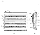
- a LCD device C configured as described above is illustrated in Fig. 7 (quoted from Fig. 7 in Patent literature 1).
- Fig. 7 (a) shows an elevation view of a conventional LCD device C
- Fig. 7 (b) shows a sectional side view of a conventional LCD device C.
- LCD device C comprises: a plurality of fluorescent tubes 31 arrayed in up and down directions, a LED 32 for emitting a red wavelength light arrayed in between each of Fluorescent tubes 31, an inverter circuit 33 for controlling a drive of Fluorescent tube 31, a LED lighting circuit 34 for controlling a light emission of LED 32, a dimming control means 35 for adjusting the emission intensity of Fluorescent tube 31 and LED 32, a power supply circuit 36, a reflection sheet 37A as a optical member of every kind, a diffusion plate 37C, a diffusion sheet 37D, a prism sheet 37E, a reflection polarizing sheet 37F, a chassis 38 for housing those aforementioned, and a LCD panel 39 for displaying an image.
- this invention has been invented considering the foregoing conditions, and the purpose of this invention is to provide a backlight unit capable of improving color purity of a prescribed emission color as well as obtaining an uniform emission colors in the entire device, and a LCD device comprising thereof.
- this invention is to be applied to a backlight unit comprising a first compensating light source for compensating emission intensity of a prescribed wavelength light of a fluorescent tube, being arranged in between each of a plurality of said fluorescent tubes arrayed in a prescribed direction, wherein said backlight unit further comprises a second compensating light source for compensating emission intensity of a prescribed wavelength light of the fluorescent tube, being arranged in the outside of each of two fluorescent tubes arranged in the outermost of said plurality of fluorescent tubes.
- a backlight unit of this invention which is constituted as mentioned above, not only compensation of emission intensity of a prescribed wavelength light of the fluorescent tube in between the fluorescent tubes, but also compensation of emission intensity of a prescribed wavelength light of the fluorescent tube in the outside of two fluorescent tubes arranged in the outermost can be realized, and therefore, color purity of the prescribed emission color can be improved, and at the same time, an uniform emission colors in the entire backlight unit can be obtained.
- the first compensating light source arranged in between each of the fluorescent tubes is for compensating emission intensity of the prescribed wavelength light of the two fluorescent tubes in its both sides.
- the second compensating light source arranged near vertical ends of the backlight unit is for compensating emission intensity of only one fluorescent tube, and thus the emission intensity of the prescribed wavelength light of said fluorescent tube is so compensated beyond necessity that the emission colors of the backlight unit may become nonuniform.
- the emission intensity in the outside of the fluorescent tube arranged in the outermost may be compensated beyond necessity.
- the emission intensity of the second compensating light source is preferably lower than that of the first compensating light source.
- the emission intensity of the second compensating light source may be nearly half of that of the first compensating light source.
- the first and second compensating light sources may be realized by, for example, a plurality of light-emitting elements arrayed in a longitudinal direction of the fluorescent tubes.
- the emission intensity can be differed between the first and second compensating light sources by switching the number of light-emitting elements to be emitted.
- the emission intensity of the second compensating light source may be controlled to nearly half of that of the first compensating light source.
- the light-emitting elements employed in the first and second compensating light sources can be standardized, and a great effect in productivity can be expected since not requiring different light-emitting elements.
- a light source substrate in which the first and second compensating light sources are mounted, may be constituted to include a plurality of segmented substrates segmented in the array direction of the fluorescent tubes, in other words, to form the light source substrate by combining the plurality of segmented substrates.
- L is the number of arrayed fluorescent tubes
- X is the number of light-emitting elements to be arrayed in a direction parallel to the array direction of the fluorescent tubes in the segmented substrate
- N is the number of the segmented substrate
- X (2M+1)/N when M is the number of inverter circuits.
- the light-emitting elements are preferably arrayed in a zigzag manner within the segmented substrates, thereby preventing color shading in emission intensity of a prescribed wavelength of the fluorescent tube that is compensated by said light-emitting elements.
- the light-emitting elements are particularly arrayed so as to be arranged, not in the both ends of one diagonal line in the segmented substrate, but in the both ends of the other diagonal line in the segmented substrate, the light-emitting elements can be arranged in a zigzag manner even in a combining site when the segmented substrates are combined. And also in this case, it is needless to say that a great effect in the productivity can be realized by the standardization of the structure of the segmented substrates.
- Fig. 1 shows a sectional side view of a LCD device A according to an embodiment of the present invention
- Fig. 2 shows a general structure of a backlight unit B according to an embodiment of the present invention: (a) is a perspective view and (b) is an elevation view.
- a schematic structure of a LCD device according to an embodiment of the present invention is described.
- LCD device A is schematically constituted by: a LCD panel 1 for displaying an image, a backlight unit B for illuminating LCD panel 1 from behind, a reflection sheet 2 as an optical member for providing the emission of Backlight unit B with color scheme property and luminance distribution property, a diffuser 3, a diffusion sheet 4, a prism sheet 5, a reflection polarizing sheet 6, and a chassis for housing those aforementioned.
- Backlight unit B is described in details.
- Backlight unit B is schematically constituted by: a plurality of fluorescent tubes 11 arrayed in up and down directions, a plurality of inverter circuits 12 for controlling the drive of each Fluorescent tube 11, LED (light emitting diode) 13 for compensating emission intensity of red wavelength light of Fluorescent tube 11 by emitting red wavelength light as being multi-arrayed in the longitudinal and array directions of Fluorescent tube 11, a plurality of LED substrates 14 (one example of a segmented substrate) mounting LED 13, a lump holder 15 for supporting Fluorescent tube 11, and a LED control circuit not shown in the figures for controlling light emission of LED 13.
- Each of LEDs 13 is an identical part internally comprising two light-emitting elements for emitting red wavelength light at nearly the same emission intensity, and the emission of each of the light-emitting elements is capable of being controlled separately by LED control circuit (not shown).
- the present embodiment is explained as referring to an example of a technique for enhancing the color purity of red by compensating the emission intensity of red wavelength light of Fluorescent tube 11 by using LED 13, however, it is needless to say that this invention finds application in other colors, for example, blue and green for enhancing color purity.
- Backlight unit B to employ substrates of an identical shape as a plurality of LED substrates 14, thereby realizing a great productivity without requiring substrates of different shapes.
- LED 13a is arranged not only in between each of Fluorescent tubes 11, but also in the outside of each of two Fluorescent tubes 11a arranged in the outermost of Fluorescent tubes 11.
- LED 13 arranged in between each of Fluorescent tubes 11 (hereinafter referred to as "LED 13b") is one example of a first compensating light source
- said LED 13a is one example of a second compensating light source.
- LED 13a and LED 13b are emitted at the same time of emission of Fluorescent tubes 11.
- LED 13b is designed so as to moderately compensate emission intensity of red wavelength light of two Fluorescent tubes 11 in both sides
- the emission intensity of red wavelength light of Fluorescent tube 11a might be compensated beyond necessity because of the emission of LED 13a that compensates emission intensity of red wavelength light of one Fluorescent tube 11. Therefore, the emission intensity of LED 13a is preferred to be lower than that of LED 13b.
- LED 13b is designed so that two light-emitting elements inside simultaneously emit
- LED 13a is designed so that only one of two light-emitting elements inside emit, both are controlled by LED control circuit. This makes the emission intensity of LED 13a half of that of LED 13b.
- the emission intensity of red wavelength light in between each of Fluorescent tubes 11, as well as the emission intensity of red wavelength light of Fluorescent tube 11 a in the outside of Fluorescent tube 11a are compensated respectively by LED 13b and LED 13a.
- LED 13b and LED 13a This enables improvement of the color purity of red wavelength light in the entire Backlight unit B, thereby obtaining a uniform emission colors in the entire Backlight unit B. Consequently, color shading in a display image in LCD device A comprising Backlight B can be prevented.
- the emission intensity of LED 13a is half of that of LED 13b, while the emission intensity of red wavelength light in between each of Fluorescent tubes 11 compensated by LED 13b as well as the emission intensity of red wavelength light of Fluorescent tube 11a in the outside of Fluorescent tube 11a compensated by LED 13a become uniform, thereby obtaining a high uniformity in emission colors in the entire Backlight unit.
- a LED is employed as a light source for compensating emission intensity of red wavelength light of Fluorescent tube 11, it is not intended to limit the scope of the present invention, and other light sources may be employed. Also, as a method for lowering the emission intensity of LED 13a than that of LED 13b arranged in between each of Fluorescent tubes 11, setting a gap between each of applied voltages, as well as employing light-emitting elements of different emission intensity at a same voltage may find application.
- FIG. 3 shows a sectional side view of LCD device A1 according to Embodiment 1 of the present invention
- Fig. 4 shows an elevation view of Backlight unit B1 installed in LCD device A1.
- the structural elements of LCD device A1 and Backlight unit B1 which are same as those of LCD device A (see Fig. 1) and Backlight unit B (see Fig. 2), are given the same codes for abbreviation of illustration and description.
- Backlight unit B1 installed in LCD device A1 comprises an inverter circuit 121 (so called “two-in-one transformer") for controlling the drive of two Fluorescent tubes 11, instead of Inverter circuit 12 installed in Backlight unit B.
- Inverter circuit 121 is more preferably employed, as the sizes of Backlight unit B as well as the number of Fluorescent tubes 11 become larger.
- the number of arrayed Fluorescent tubes 11 can be specified by the number of Inverter circuits 121 driving two Fluorescent tubes 11. In concrete terms, the number of arrayed Fluorescent tubes 11 is twice of the number of Inverter circuits 121.
- X (2M+1)/N
- M the number of Inverter circuits 121
- X is the number of LEDs 13 arrayed in a direction parallel to the array direction of Fluorescent tubes 11 in LED substrate 14a
- N is the number of LED substrates 14a.
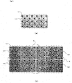
- FIG. 5 shows a view for describing a deformation example of LED substrate 14 (14a)
- Fig. 6 shows a view for describing another deformation example of LED substrate 14 (14a).
- LEDs 13 are arrayed in a zigzag manner. With such array of LEDs 13, the uniformity in emission colors in the entire Backlight unit B (B1) is enhanced.
- LEDs 13 are arrayed in both ends of the both diagonal lines in said LED substrate 141. Therefore, as illustrated in Fig. 5(b), when a plurality of LED substrates 141 is combined, LEDs 13 are not arrayed in a zigzag manner within the combining site (the area R in the illustration). Also, when a LED substrate having an opposite array to LED substrate 141, that is, not having LEDs 13 in both ends of the both diagonal lines, is manufactured, the array of LEDs 13 in a zigzag manner within such combining site can be realized, though failing to achieve a great productivity.
- LEDs 13 are arranged in both ends of one diagonal line, and arrayed in a zigzag manner so as not to be arranged in the both ends of the other diagonal line.
- the number of arrayed LEDs 13 in each of horizontal directions is the same, while the number of arrayed LEDs 13 in each of vertical directions is the same.
Landscapes
- Engineering & Computer Science (AREA)
- Physics & Mathematics (AREA)
- Computer Hardware Design (AREA)
- General Physics & Mathematics (AREA)
- Theoretical Computer Science (AREA)
- Liquid Crystal (AREA)
- Planar Illumination Modules (AREA)
- Non-Portable Lighting Devices Or Systems Thereof (AREA)
Applications Claiming Priority (1)
| Application Number | Priority Date | Filing Date | Title |
|---|---|---|---|
| JP2005257718A JP4467491B2 (ja) | 2005-09-06 | 2005-09-06 | バックライト装置,液晶表示装置 |
Publications (2)
| Publication Number | Publication Date |
|---|---|
| EP1760686A2 true EP1760686A2 (de) | 2007-03-07 |
| EP1760686A3 EP1760686A3 (de) | 2007-09-12 |
Family
ID=37607074
Family Applications (1)
| Application Number | Title | Priority Date | Filing Date |
|---|---|---|---|
| EP06018693A Withdrawn EP1760686A3 (de) | 2005-09-06 | 2006-09-06 | Rückbeleuchtungseinheit und Flüssigkristallanzeigevorrichtung |
Country Status (3)
| Country | Link |
|---|---|
| US (1) | US7597451B2 (de) |
| EP (1) | EP1760686A3 (de) |
| JP (1) | JP4467491B2 (de) |
Cited By (1)
| Publication number | Priority date | Publication date | Assignee | Title |
|---|---|---|---|---|
| CN103017015A (zh) * | 2011-09-21 | 2013-04-03 | 佳能株式会社 | 光源设备 |
Families Citing this family (17)
| Publication number | Priority date | Publication date | Assignee | Title |
|---|---|---|---|---|
| KR101183447B1 (ko) * | 2005-06-30 | 2012-09-17 | 엘지디스플레이 주식회사 | 액정표시장치용 반사시트 및 이를 이용한백라이트어셈블리와 액정표시장치모듈 |
| US7976176B2 (en) * | 2005-09-28 | 2011-07-12 | Sharp Kabushiki Kaisha | Lighting unit, backlight unit, and liquid crystal display device |
| US8045096B2 (en) * | 2005-09-28 | 2011-10-25 | Sharp Kabushiki Kaisha | Lighting unit including alternately arrange first and second light sources, backlight unit, liquid crystal display device |
| KR101352104B1 (ko) | 2007-05-08 | 2014-01-14 | 엘지디스플레이 주식회사 | 백 라이트 유닛 및 이를 이용한 액정 표시장치 |
| KR101339768B1 (ko) * | 2007-08-30 | 2013-12-11 | 삼성전자주식회사 | 면 광원 장치 및 이를 구비하는 lcd 백라이트 유닛 |
| KR101394007B1 (ko) * | 2007-09-11 | 2014-05-13 | 엘지이노텍 주식회사 | 라이트 유닛 및 이를 구비한 디스플레이장치 |
| JP2010062006A (ja) * | 2008-09-04 | 2010-03-18 | Epson Imaging Devices Corp | 照明装置、電気光学装置及び電子機器 |
| TW201027186A (en) * | 2009-01-13 | 2010-07-16 | Chunghwa Picture Tubes Ltd | Backlight module for a scanning backlight LCD |
| US8376582B2 (en) | 2009-03-18 | 2013-02-19 | Koninklijke Philips Electronics N.V. | LED luminaire |
| US8414155B2 (en) | 2009-03-18 | 2013-04-09 | Koninklijke Philips Electronics N.V. | LED luminaire |
| US8123378B1 (en) | 2009-05-15 | 2012-02-28 | Koninklijke Philips Electronics N.V. | Heatsink for cooling at least one LED |
| WO2011004623A1 (ja) * | 2009-07-09 | 2011-01-13 | シャープ株式会社 | 照明装置、表示装置、及びテレビジョン受像器 |
| USRE47656E1 (en) | 2009-08-27 | 2019-10-22 | Lg Electronics Inc. | Optical assembly, backlight unit and display apparatus thereof |
| EP2470947B1 (de) * | 2009-08-27 | 2016-03-30 | LG Electronics Inc. | Optische anordnung, hintergrundbeleuchtungseinheit und anzeigevorrichtung dafür |
| US8506127B2 (en) | 2009-12-11 | 2013-08-13 | Koninklijke Philips N.V. | Lens frame with a LED support surface and heat dissipating structure |
| JP5415618B2 (ja) * | 2010-06-17 | 2014-02-12 | パナソニック液晶ディスプレイ株式会社 | 液晶表示装置及びテレビ受像機 |
| WO2019217408A1 (en) * | 2018-05-07 | 2019-11-14 | Corning Incorporated | Backlight unit with improved 2d local dimming |
Citations (1)
| Publication number | Priority date | Publication date | Assignee | Title |
|---|---|---|---|---|
| JP2004139876A (ja) | 2002-10-18 | 2004-05-13 | Sharp Corp | 照明装置、バックライト装置、液晶表示装置 |
Family Cites Families (15)
| Publication number | Priority date | Publication date | Assignee | Title |
|---|---|---|---|---|
| US3346689A (en) | 1965-01-29 | 1967-10-10 | Philco Ford Corp | Multilayer circuit board suing epoxy cards and silver epoxy connectors |
| DE69418502T2 (de) * | 1993-02-01 | 2000-02-24 | Tosoh Corp | Vorrichtung zur Hintergrund-Beleuchtung |
| JPH11202330A (ja) | 1998-01-16 | 1999-07-30 | Sony Corp | バックライトユニット |
| US6657698B1 (en) | 1999-08-06 | 2003-12-02 | Rainbow Displays, Inc. | Design features optimized for tiled flat-panel displays |
| JP2001135118A (ja) | 1999-11-02 | 2001-05-18 | Toshiba Corp | 面光源装置及びそれを用いた平面表示装置 |
| JP2002258281A (ja) | 2001-03-01 | 2002-09-11 | Furuno Electric Co Ltd | 液晶ディスプレイ、輝度調整装置および表示装置 |
| JP3927011B2 (ja) | 2001-08-20 | 2007-06-06 | 株式会社 日立ディスプレイズ | 液晶表示装置とその駆動回路 |
| JP2003330424A (ja) | 2002-05-10 | 2003-11-19 | Hitachi Ltd | 液晶表示装置 |
| CN1706023A (zh) * | 2002-10-14 | 2005-12-07 | 皇家飞利浦电子股份有限公司 | 生成白光的发光体 |
| JP2004246117A (ja) | 2003-02-14 | 2004-09-02 | Matsushita Electric Ind Co Ltd | バックライト装置 |
| DE10338691B4 (de) * | 2003-08-22 | 2005-07-28 | Siemens Ag | Hintergrundbeleuchtung für Flüssigkristallanzeigen |
| JP4086837B2 (ja) | 2003-12-03 | 2008-05-14 | シャープ株式会社 | 照明装置およびそれを備えた表示装置 |
| KR101029432B1 (ko) | 2003-12-29 | 2011-04-14 | 엘지디스플레이 주식회사 | 액정표시장치의 구동방법 및 구동장치 |
| JP2005210028A (ja) | 2004-01-26 | 2005-08-04 | Kyocera Corp | 多数個取り配線基板 |
| KR101090751B1 (ko) * | 2004-06-29 | 2011-12-08 | 엘지디스플레이 주식회사 | 배광장치를 포함하는 액정표시장치 |
-
2005
- 2005-09-06 JP JP2005257718A patent/JP4467491B2/ja not_active Expired - Lifetime
-
2006
- 2006-09-05 US US11/515,007 patent/US7597451B2/en not_active Expired - Fee Related
- 2006-09-06 EP EP06018693A patent/EP1760686A3/de not_active Withdrawn
Patent Citations (1)
| Publication number | Priority date | Publication date | Assignee | Title |
|---|---|---|---|---|
| JP2004139876A (ja) | 2002-10-18 | 2004-05-13 | Sharp Corp | 照明装置、バックライト装置、液晶表示装置 |
Cited By (1)
| Publication number | Priority date | Publication date | Assignee | Title |
|---|---|---|---|---|
| CN103017015A (zh) * | 2011-09-21 | 2013-04-03 | 佳能株式会社 | 光源设备 |
Also Published As
| Publication number | Publication date |
|---|---|
| US20070058358A1 (en) | 2007-03-15 |
| JP4467491B2 (ja) | 2010-05-26 |
| JP2007073290A (ja) | 2007-03-22 |
| EP1760686A3 (de) | 2007-09-12 |
| US7597451B2 (en) | 2009-10-06 |
Similar Documents
| Publication | Publication Date | Title |
|---|---|---|
| US7597451B2 (en) | Backlight unit and liquid crystal display device | |
| KR101237788B1 (ko) | 엘이디 발광유닛 및 엘이디 백라이트어셈블리와액정표시장치모듈 | |
| US8305516B2 (en) | Liquid crystal display device | |
| EP1640792B1 (de) | Rückbeleuchtungsanordnung und Anzeigegerät, welche die Rückbeleuchtungsanordnung beinhaltet | |
| KR101189135B1 (ko) | 액정표시장치모듈 | |
| KR100959157B1 (ko) | 다중 디스플레이 패널을 이용한 멀티스크린 장치 | |
| TWI428670B (zh) | A liquid crystal display device for backlighting and a liquid crystal display device using the same | |
| KR101594616B1 (ko) | 백라이트 유닛 및 이를 구비한 액정표시장치 | |
| JP2007073527A (ja) | 蛍光ランプガイドホルダ及びこれを利用したバックライトアセンブリと液晶表示モジュール | |
| CN1987593A (zh) | 面状照明装置及以面状照明装置为背光源的液晶显示装置 | |
| US20060193132A1 (en) | Backlight assembly and liquid crystal display device using the same | |
| US20110211139A1 (en) | Display device | |
| US7264373B2 (en) | Backlight module | |
| JP2006278077A (ja) | バックライト装置及び液晶表示装置 | |
| US7377677B2 (en) | Backlight assembly with excellent light efficiency and display device having the same | |
| US9004710B2 (en) | Illumination device, display device, television receiving device | |
| CN101075413B (zh) | 显示装置及其驱动方法 | |
| KR101281520B1 (ko) | 백 라이트 장치 및 화상 표시 장치 | |
| KR101261881B1 (ko) | 발광다이오드 어셈블리 및 이를 포함하는 액정표시장치모듈 | |
| KR101669642B1 (ko) | 백라이트유닛 및 이에 이용되는 led들의 서브 어레이 장치 | |
| KR20060000814A (ko) | 액정표시장치의 백라이트 유닛 | |
| KR101002310B1 (ko) | 발광램프 및 이를 이용한 백라이트 유닛 | |
| JP2018181809A (ja) | 照明装置、表示装置及びテレビ受信装置 | |
| KR101929035B1 (ko) | 백라이트 어셈블리 | |
| KR101107684B1 (ko) | Led 어레이 및 이를 이용한 백 라이트 유닛 |
Legal Events
| Date | Code | Title | Description |
|---|---|---|---|
| PUAI | Public reference made under article 153(3) epc to a published international application that has entered the european phase |
Free format text: ORIGINAL CODE: 0009012 |
|
| AK | Designated contracting states |
Kind code of ref document: A2 Designated state(s): AT BE BG CH CY CZ DE DK EE ES FI FR GB GR HU IE IS IT LI LT LU LV MC NL PL PT RO SE SI SK TR |
|
| AX | Request for extension of the european patent |
Extension state: AL BA HR MK YU |
|
| RIC1 | Information provided on ipc code assigned before grant |
Ipc: G09G 3/34 20060101AFI20070118BHEP |
|
| PUAL | Search report despatched |
Free format text: ORIGINAL CODE: 0009013 |
|
| AK | Designated contracting states |
Kind code of ref document: A3 Designated state(s): AT BE BG CH CY CZ DE DK EE ES FI FR GB GR HU IE IS IT LI LT LU LV MC NL PL PT RO SE SI SK TR |
|
| AX | Request for extension of the european patent |
Extension state: AL BA HR MK YU |
|
| 17P | Request for examination filed |
Effective date: 20080128 |
|
| 17Q | First examination report despatched |
Effective date: 20080228 |
|
| AKX | Designation fees paid |
Designated state(s): DE ES FR GB |
|
| STAA | Information on the status of an ep patent application or granted ep patent |
Free format text: STATUS: THE APPLICATION IS DEEMED TO BE WITHDRAWN |
|
| 18D | Application deemed to be withdrawn |
Effective date: 20151215 |