EP1760663A2 - Transfer of attributes between geometric surfaces of arbitary topologies with distortion reduction and discontinuity preservation - Google Patents
Transfer of attributes between geometric surfaces of arbitary topologies with distortion reduction and discontinuity preservation Download PDFInfo
- Publication number
- EP1760663A2 EP1760663A2 EP06253964A EP06253964A EP1760663A2 EP 1760663 A2 EP1760663 A2 EP 1760663A2 EP 06253964 A EP06253964 A EP 06253964A EP 06253964 A EP06253964 A EP 06253964A EP 1760663 A2 EP1760663 A2 EP 1760663A2
- Authority
- EP
- European Patent Office
- Prior art keywords
- target
- geometry
- source
- dimensional
- dimensional mesh
- Prior art date
- Legal status (The legal status is an assumption and is not a legal conclusion. Google has not performed a legal analysis and makes no representation as to the accuracy of the status listed.)
- Withdrawn
Links
Images


Classifications
-
- G—PHYSICS
- G06—COMPUTING OR CALCULATING; COUNTING
- G06T—IMAGE DATA PROCESSING OR GENERATION, IN GENERAL
- G06T19/00—Manipulating 3D models or images for computer graphics
-
- G—PHYSICS
- G06—COMPUTING OR CALCULATING; COUNTING
- G06T—IMAGE DATA PROCESSING OR GENERATION, IN GENERAL
- G06T17/00—Three dimensional [3D] modelling, e.g. data description of 3D objects
- G06T17/20—Finite element generation, e.g. wire-frame surface description, tesselation
Definitions
- Attributes may be transferred from a geometric surface having one topology, such as a polygon mesh, to another geometric surface of a different topology, such as a different polygon mesh.
- Example attributes that may be transferred include, but are not limited to, color, texture coordinates, animation values and rendering values that may be associated with a vertex, edge, face or face corner (also called a face-vertex pair or polygon nodes).
- Attribute transfer is commonly used in the context of the creation of three dimensional (3D) objects for realistic visual entertainment, such as video games and films.
- 3D objects are defined by 3D geometric surfaces that typically have many associated attributes, such as texture coordinates, high quality textures, specular maps, normal maps, face materials, animation shapes and deformation weights.
- artists often design many similar 3D objects and create similar surface attributes and animation data for each of them.
- artists may have to design many characters, and create for each of them various actions, e.g., stand, sit, run, various expressions, e.g., smile, close eyes, say "A", and various colors and textures, e.g., normal maps, specular maps, surface parameterization for texture coordinates.
- various expressions e.g., smile, close eyes, say "A”
- various colors and textures e.g., normal maps, specular maps, surface parameterization for texture coordinates.
- the topologies of the characters are often different, e.g., different number of polygons or different assembly, all the surface attributes often are created separately for each object.
- Artists also may create the same character at different levels of detail, each of which might have different topologies, but for which the surface attributes should be similar.
- the closest surface or closest vertex in the source geometry is determined. Given the closest surface or vertex locations on the source geometry, the surface attribute values at these locations are computed, optionally by interpolating between the closest anchor points for the surface attributes in the source geometry.
- Distortion artifacts may arise due to the nature of the closest surface and closest vertex calculations between the source and target geometries. Such distortion cannot be avoided in general, and generally arise around convex and concave portions of the surfaces.
- a surface attribute discontinuity is a sharp variation of an attribute relative to the surface.
- An example is a well-defined frontier between two colors.
- attribute discontinuities define paths made of one or more connected edges. Discontinuity paths can intersect at vertices. Surface attribute discontinuities and their intersections often define visually important features. The general closest surface and closest vertex algorithms will not necessarily preserve such surface attribute discontinuities
- attribute transfer should not be based on finding an ideal correspondence between source and target geometries. Instead, attribute transfer should be based on the general spatial placement that was preliminarily done by an artist, with attributes propagated based on that spatial relationship. In such a context, having multiple source regions corresponding to a same target region or vice versa can actually be the behavior wanted by the artist. Having a spatial correspondence which is pre-defined and globally controlled by the artist significantly reduces several types of undesirable distortions and artifacts, because most proportion or orientation mismatches between the source(s) and the target geometries reflect a choice taken by the artist.
- Some distortions still arise, however, if a typical closest surface or closest vertex algorithm is used determine the correspondence between the artist aligned source and target geometries. These distortions can be reduced by locally redistributing the identified correspondence locations on the source geometry so as to avoid these artifacts.
- Methods for performing such local redistribution include an inverse ray casting technique and a modified inverse ray casting technique. This technique ensures that concave regions of the source geometry are mapped to the target geometry, and that convex edges or vertices of the source geometry do not map to a large area on the target geometry.
- Attribute discontinuities in the source geometry are preserved in the target geometry by relating discontinuous edges in the source geometry to the target geometry. This relationship may map each discontinuous edge in the source geometry locally to the target geometry. Alternatively, this relationship may involve mapping discontinuous paths globally to the target geometry.
- the quality of attribute transfer is improved by reducing distortions introduced by the method through which correspondence between a target geometry and a source geometry is determined and/or by preserving discontinuities in attributes from the source geometry by relating discontinuous edges in the source geometry to the target geometry.
- Attributes may be transferred between any two arbitrary geometrical primitives, such as a polygon mesh, a NURBS surface mesh or other object that is a combination of vertices and edges that define faces in three dimensions.
- An example of a three-dimensional geometrical primitive is a mesh.
- a mesh is defined by specifying faces, vertices and edges. The vertices and edges define n-sided faces. Some three-dimensional meshes have edges that are not line segments, but may be curves. Some three-dimensional meshes also have faces that are not planar.
- a mesh generally is represented in a computer by three arrays that store information about the vertices, edges (whether line segments or curves) and faces (whether planar or not).
- the data structure representing each vertex may include, for example, data defining its position as well as the indices of the neighboring edges and faces.
- the data structure representing each edge may include, for example, data defining the indices of its end vertices and the indices of the two adjacent faces.
- the data structure representing each face may include, for example, data defining the indices of its neighboring faces, edges and vertices.
- attributes such as color, texture, animation values and rendering values
- the anchor may be a vertex, node, edge or face of a mesh, for example.
- Example attributes that may be associated with vertices of a mesh include, but are not limited to weight maps (scalar values for various uses), envelope weight maps (also called “deformation weights”), specular maps, and animation shapes (vectors).
- Example attributes that may be associated with nodes of a mesh, which are face corners or vertex polygon pairs include, but are not limited to texture coordinates, vertex colors, and user-defined normals.
- Example attributes that may be associated with polygons of a mesh include, but are not limited to, textures, face material groups and clusters (for various uses).
- Example attributes that may be associated with edges of a mesh include, but are not limited to, information about hard edges or crease edges.
- artists may create several different meshes for the same character, or may create several different characters that have a need for sharing surface attributes. In these cases, it would save significant time to be able to readily transfer attributes from one mesh to another.
- a dataflow diagram illustrates an example system 100 for transferring attributes from a source geometry 102 with attributes to a target geometry 104.
- the source geometry and target geometry are input to a correspondence calculator 106 which determines, using a closest surface, closest vertex, or other equivalent method, for each vertex in the target geometry the corresponding surface on the source geometry.
- These correspondences 108 between vertices and surfaces are input, along with the source and target geometries 102 and 104 to a discontinuity preserving mapping 110 of the attributes from the source geometry to the target geometry.
- the result is the target geometry with attributes, as indicated at 112.
- the implementation of the discontinuity preserving mapping 110 is generally independent of the implementation of the correspondence calculator 106.
- An artist initiates the attribute transfer process by placing the source and target geometries in alignment with each other. Given this placement, there are several methods that may be used to compute the correspondence between the source and target geometries. Such methods include closest surface, closest vertex and, as described below, inverse ray casting techniques.
- the closest source surface location is determined in the following way.
- the closest surface point from a geometric surface A to a vertex V of a surface B positioned at a 3D position P(V) is, among all possible surface points in A (either on a vertex, on an edge, or inside a face), the surface location L at a 3D position P(L) that minimizes the Euclidean distance between P(V) and P(L).
- this relation in not symmetrical; if L is the closest surface location on a surface A from surface B's vertex V, vertex V is not, in general, the closest surface location on the surface B from location L.
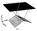
- Distortions may be introduced by determining the closest surface or closest vertex in this manner if a non-null area of a target surface corresponds to a convex edge or a convex vertex. The more the convexity is pronounced, and the farther the target surface is from the edge or the vertex, the greater the size of this non-null area of the target surface will be. As shown in Fig. 2, all of the points in region R of the target surface B correspond to the edge L in the source surface A.
- the variation in, i.e., the derivative of, the attribute values over the source primitive around the convex edge or vertex is non-null
- a resulting lack of variation over the target region R that corresponds to the source convex edge or vertex produces a significant visible artifact.
- Such an artifact is particularly likely to occur when transferring attributes from a low resolution mesh to a high resolution mesh.
- the vertex density is higher on the target surface, which increases the probability that many adjacent target vertices are close to the same source convex edge or vertex.
- a symmetrical problem occurs with concavities.
- No area of a target surface placed above a concave edge or a concave vertex in the source surface corresponds to face portions of the source surface adjacent to this edge or vertex.
- the variation in, i.e., the derivative of, the attribute values over the source primitive around the concave edge or vertex is non-null, then a discontinuity will arise in the attributes on the target surface due to non-coverage of some of the source geometry.
- Such an artifact also is likely to occur when transferring from a low resolution mesh to a high resolution mesh, for reasons similar to the case of convexities.
- the closest surface and closest vertex locations may be locally redistributed to provide a more uniform coverage of the problematic source edges.
- topological information e.g., connectivity between the faces, vertices and edges, triangulated representation of the polygons, and positional information, e.g., vertex positions, vertex normal values, about the adjacent faces surrounding that location is gathered.
- positional information e.g., vertex positions, vertex normal values
- a correspondence or remapping function is applied locally which either does not produce the undesired distortion or reverts it.
- a globally applied correspondence or remapping function is applied and then refined locally using another correspondence or remapping function.
- Fig. 3 represents a two-dimensional (2D) simplification of the problem, such that the source geometry is made of connected line segments instead of connected triangles.
- a set S of faces is built, including all faces adjacent to source geometry's component (face, edge or vertex), e.g., vertex L, corresponding to the target vertex V.
- a second set S2 of faces is built by including all source faces that are adjacent those in S.
- set S2 includes set S.
- a third set S3 of triangles T is built from the tessellation of the faces in set S2.
- vertex normals (N1, N2, N3) are computed. These vertex normals are interpolated over the local adjacent faces to produce interpolated face normals (e.g., N4, N5).
- a source surface location S can be identified from the triangle T such that a line starting from S and going in the direction of its interpolated face normal (e.g., N4) passes by the target vertex V. The closest surface location for the target vertex V is set to this point S. If no such S exists, then we continue with another triangle of the set S3.
- the original source geometry's component e.g., vertex L
- a closest surface location is determined based on that component.
- the volume defined by the lines passing through the interpolated normals of the local adjacent faces will include the target vertex T.
- the normals N1 and N2 defined at the vertices are interpolated along the faces to produce different vectors, these interpolated normals often define a one-to-one correspondence with the positions within that volume. This correspondence provides a uniform mapping from the target vertices to the source faces and their attribute variations even in concave and convex areas.
- Fig. 4 represents a 2D simplification of the problem, such that the source geometry is made of connected line segments instead of connected triangles. Barycentric coordinates for a line segment are made of two values, A and B in Fig. 4, which would become three values for a 3D triangle, with a barycentric coordinate for each triangle vertex.
- This method starts from the same triangle set S3 that was defined for the inverse ray-casting method described above in connection with Fig. 3. For each triangle T in the set S3, a plane P is identified which is parallel to the triangle T and passes through the target vertex V.
- the intersection point (IP1, IP2, IP3) between the plane P and the line passing through the vertex TVi in the direction of its corresponding normal TNi is determined.
- the barycentric weights of the target vertex V relative to the intersection points IP1, IP2 and IP3 is then determined. If the target vertex V is not included in the triangle IP1-IP2-IP3, then we continue with another triangle of the set S3. Otherwise, these barycentric weights are then applied with respect to the source vertices (TV1, TV2 and TV3) to define a source surface location S.
- the source geometry component e.g., vertex L
- a user-provided threshold can define the distance (usually small) which defines if two vertices overlap.
- Attribute discontinuities that must be preserved on the target geometry can have various origins. In most cases, they come from attribute discontinuities that were present in the source geometries and have a correspondence to the target geometry.
- a source surface may have two colors, red and blue, and each face is either red or blue. The edges that are adjacent to red and blue faces are discontinuous.
- a discontinuity is caused by a topological or geometrical mismatch between the sources and the target geometries. For example, if one were to transfer colors from two adjacent spheres, a blue and a red one, to a bigger target sphere containing the spheres, there will be some edges on the target sphere such that one of its vertices correspond to the red sphere and the other one corresponds to the blue sphere. Since there is no color interpolation between the colors of the source spheres, this topological mismatch should be preserved as a color discontinuity on the target geometry.
- discontinuity due to a mismatch between source and target geometries, would occur even if the source geometry has only one piece and no discontinuities.
- An example could be an open torus shape (C shape) with a red and a blue pole, the red being interpolated to blue along the torus. If the color were transferred from this torus to a closed torus (O shape), there will be some edges on the target mesh such that one point corresponds to the red pole and the other corresponds to the blue pole. Again, this mismatch should be preserved as a discontinuity, because even if the source primitive does not have a discontinuity, the propagation of the attribute to the surrounding volume through the closest surface relationship defines a clear discontinuity in that volume.
- Face attributes such as materials
- these can be treated in the same way as discontinuities at edges by considering the edges defining the contour of the connected faces having a specific attribute.
- An edge is called a discontinuous edge if there is a discontinuity in the attributes between the faces adjacent the edge.
- a graph may be defined to connect sets of discontinuous edges. Such graphs define discontinuous paths on the source geometries. These discontinuous paths often enclose connected regions of the geometry. However, in general, discontinuous paths can be open. An example of an open discontinuous path is a single discontinuous edge in the middle of a plane. Discontinuous paths can intersect. Such intersections occur at source vertices that are adjacent to three or more discontinuous edges.
- a discontinuity circuit is a circuit of connected discontinuous edge's half edges such that all the consecutive face corners along this path have no attribute discontinuity.
- a set of discontinuity circuits that describe all discontinuities can always be defined. Discontinuity circuits are always closed. It is possible for a discontinuity circuit to contain both half-edges of an edge.
- the correspondence of a discontinuity circuit (or a portion of it) from the source geometry on the target surface is its "projection" onto the target surface. Because the surface correspondence between the source and target geometries is not a one-to-one relationship, it is possible for a discontinuity circuit (or a portion of it) to be projected at various target surface locations. Moreover, because there is no guarantee about the quality of the surface correspondence, the projected circuit can cross itself, can represent only a portion of a source circuit, and can even be reverted or partially reverted relative to its source counterpart. For example, projecting a linear circuit onto a sphere creates a circle on that sphere.
- the following method preserves the discontinuity types discussed above, and provides good results even with ill-defined or distorted projected circuits. Thus, this method focuses more on preserving discontinuities in source attributes than discontinuities caused by a topological or geometrical mismatch.
- step 500 On the surface geometry, the discontinuity circuits are identified and information about the source attributes is collected in step 500.
- the correspondences between the target vertices and source surfaces is obtained in step 502.
- step 504 these correspondences are processed to ensure that target vertices are not mapped to discontinuities in the source surface.
- Step 500 can be done separately from steps 502 and 504, whether in parallel or in a different order.
- the intersections between the target edges and the discontinuity circuits are then determined in step 506.
- the projected discontinuity circuits are then reconstructed in step 508.
- the discontinuity circuits are then related to target edges in step 510.
- discontinuity circuits in the source geometry are identified and information about them is gathered.
- the discontinuity circuits are defined by identifying all discontinuous half edges, such as edge E.
- a vertex of a discontinuous half edge is selected, such as vertex V, and the discontinuity circuit D including it is created by traversing the source geometry.
- the source geometry is traversed along all discontinuous half edges until an extensive list of the discontinuity circuits is created.
- Each discontinuity circuit is numbered, and an ordered list of the half edges it includes is created. For each discontinuity circuit, the half edges are numbered, such as shown in Fig. 6, and their edge orientation relative to the circuit order is recorded.
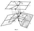
- many adjacent target vertices can correspond to the same source convex edge, such as shown in Fig. 7.
- points P1, P2, P3 and P4 in the target surface T all are mapped to points on the path containing points V1, V2 and V3.
- Points P1, P2 and P3 all are mapped to points on the same edge containing V1 and V2.
- the fact that the same portion of a source discontinuity circuit can correspond to a target region that can be larger than the width of one or many target polygons can prevent the next steps of the algorithm from preserving the source discontinuities properly.
- the algorithm requires that each portion of a projected discontinuity circuit fit into a path of connected adjacent target polygons, which has a width of at most one polygon.
- a method is applied in order to reduce the width of the target polygon path corresponding to a projected discontinuity circuit.
- This method applies a micro-displacement to the surface locations so they no longer fall exactly on a discontinuity edge (step 504 in Fig. 5).
- This step is optional when using an inverse ray casting method or other method for determining the correspondences that otherwise reduces distortion in the mapping of the source surface to the target surface, but may nonetheless be applied to reduce the number of correspondences that fall on edges in the source geometry.
- a plane P is defined.
- Plane P is a bisector plane passing through the source discontinuous edge E and forming equal angles with the planes passing through faces A and B adjacent to the edge. If the target vertex is on the same side relative to plane P as the face A, then the source location corresponding to the target vertex will be displaced onto the face A, such as shown at V2. If the target vertex is on the same side relative to plane P as the face B, then the source location corresponding to the target vertex will be displaced onto the face B, such as shown at V1. If the target vertex happens to be directly on the plane P, then its corresponding source location is kept on the discontinuous edge.
- the intersections of the discontinuity circuits with edges in the target geometry are then determined.
- the correspondence of the target edges with the source surface is determined.
- the edge E1 in the target surface T corresponds to a path P1 on the source surface S.
- the intersection point IPT on the target edge E1 which corresponds to the intersection point IPS on path P1 that intersects the discontinuity circuit on the surface S.
- This determination does not involve a projection, because projection is not a bidirectional relationship. Therefore, the process begins by identifying a short path linking source surface locations L1 and L2 corresponding to the vertices V 1 and V2 of the target edge E.
- Various methods can be used to find point IPS, such as traversing the source geometry in straight line, finding the actual shortest path between locations L1 and L2 (which is more computationally expensive), or traversing the source geometry along the intersection between the source surface and a plane which is perpendicular to the surface and which passes through the two surface locations L1 and L2.
- a short path linking the two source locations L1 and L2 exists, then, by using the description of the path and the information collected (as described in connection with Fig. 6, all the intersections between the path and the source circuit half edges are recorded. For each intersection, various information is stored, such as the target edge, the intersection position along the target edge path (from 0 to 1), the source circuit, and the position on the half edge (from 0 to 1) and in the source circuit. If many overlapping source surface locations correspond to a target vertex, the paths between all combinations of the corresponding overlapping source locations corresponding to target edge's end vertices should be tried, and the best ones should be kept.
- a short path linking the two surface locations does not exist, the target edge is recorded as part of a geometrically (or topologically) discontinuous intersection. More precisely, a short path will not be found if the surface locations L1 and L2 are on different source primitives, or if the path encounters a topological discontinuity, e.g., a surface boundary such as at D, or if the path linking the two surface locations is too long relative to some threshold.
- An example maximum path length threshold may be 3 times the distance between the two source surface locations, but can be made a user defined parameter. Two distinct intersections are defined and recorded in this case.
- the farthest edge location is identified such that a short path exists between the source surface location corresponding to the target edge extremity and the source surface location corresponding to that edge location.
- the farthest edge location for each edge extremity, along with their corresponding source surface locations, are recorded as a geometrical discontinuity intersection.
- the set of intersections is used to build the projected discontinuity circuits on the target surface.
- a target edge intersection that has not yet been processed such as IPT
- this intersection is recorded as the first element of a new intersection list, and is placed in a processed intersections set.
- an intersection of the same type which has not been processed and which is the closest to the current one in term of order within the source circuit is identified (e.g., IPN).
- IPN intersection of the same type which has not been processed and which is the closest to the current one in term of order within the source circuit.
- Two intersections are of a same type if they are part of a same source circuit or if they have both been marked as being a geometrical (or topological) discontinuity.
- intersection is added to the intersection list and to the processed list, along with the target face which is linking this intersection to the previous one, e.g., face A.
- target face which is linking this intersection to the previous one, e.g., face A.
- a polygon stripe surrounding the projected discontinuity circuit is defined. The process continues to identify adjacent intersections (e.g., IPQ on face B) of the same type until there are no more compatible intersections.
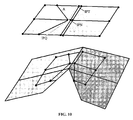
- the projected circuits are related to the target geometry edges, as will now be described in connection with Fig. 11.
- One way to create this relationship is to topologically create edges on the target geometry.
- Another way is to find the target edge path which is the best fit for the projected circuit path location.
- the way used can be a user defined parameter.
- Topologically creating edges on the target geometry is performed using the information recorded in the previous steps. Of course, if the topology of the target mesh fits exactly with the projected circuit, no topological change is required. Otherwise, for all projected circuit lists, vertices on the target mesh are created by splitting the target edges at their intersection ratio, such as shown at K1-K3. Then, all the projected circuit vertices are linked by creating edges, e.g., edges E1 and E2, also called splitting faces, and linking them in projected circuit order. In the case of intersections of three or more circuits, an inner face point corresponding to the circuit intersection location is created and connected to all intersections of surrounding target edges. In other words, each face in the polygon stripe defined by a projected circuit is split at the midpoint between the projected circuit and the adjacent projected circuit.
- the property values of the related source discontinuity values are then copied.
- the property values are the ones along the circuit at the intersection location with the target edge path.
- these values are the ones corresponding to the farthest edge locations on the proper projected circuit side.
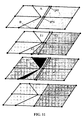
- Determining the target edge path which is the best fit relative to the projected circuit begins by generating, for each target geometry faces, a list of all projected circuit intersections which are passing through the face, e.g., edges I1 and 12, is generated.
- each projected circuit portion intersecting the target face will intersect it at two locations. Different portions of the same circuit can intersect a face.
- the various circuit portions define two or more partitions of the target polygon, e.g., areas P1 and P2. It is then determined which partition of the target polygon has the biggest area. This area can either be computed in the target surface or in the corresponding source surface. For simplicity, our implementation computes the area of the portion in source surface space.
- This area is computed as the area of the polygon formed by the source edges of the circuit portion, the intersection points between the source discontinuity circuit and the path corresponding to the target edge on the source surface, and the source surface locations corresponding to the vertices of the target polygons included in the partition.
- the circuit portions which are part of the biggest polygon partition, e.g., P1 will be marked so they are later snapped to the interior half edges of the target face.
- the other circuits will be marked so they are later snapped to the exterior half edges of the target face. In the example shown in Fig. 11, this would mean that I1 and I2 are snapped to T1 and T2.
- each projected discontinuity circuit is processed in order to find a corresponding target edge circuit.
- the ordered face stripe corresponding to a projected discontinuity circuit is already known from the information recorded in prior steps.
- a face stripe can define multiple possible edge paths. This ambiguity is resolved by the information collected previously, which states if circuit portions should correspond to the inner or the outer half edges of each target face.
- the attribute values from source circuits are propagated to the corresponding target edge circuits.
- the closest circuit property value is copied to the target components. For each target face corner on which the discontinuity has to be propagated, the closest circuit location is found in source geometry's space, relative to the surface location corresponding to the target vertex. The closest circuit location is searched among the circuit portions being projected to the adjacent target polygons.
- Another possible method is to first find a starting point of the projected circuit onto the target geometry, and then define the circuit trajectory on the target surface by walking in parallel on the source and the target geometry.
- the correspondence between the source circuit and the target projected circuit could be determined by various methods such as by using a spatial correspondence method mapping from the source to the target, or by localizing the source circuit positions relatively to the source surface locations corresponding to the target vertices (e.g., by using barycentric coordinates).
- All source discontinuity edges could be treated as surface boundaries (topological discontinuities). Methods similar to the ones used to preserve the geometrical (or topological) discontinuities then may be applied. In this case, it would not be necessary to collect information about the discontinuity circuits; however, the attribute discontinuities around the discontinuous edges would, in effect, be preserved only locally.
- a target edge corresponds to some source locations, and these locations have some precise UV values, where a UV value is a Cartesian coordinate pair in the surface attribute plan. This correspondence gives to a target edge a corresponding UV segment in UV space. This segment can then be tested for intersections with source geometry's discontinuous edges' corresponding UV segments.
- a less robust method, which could replace the steps of Fig. 5, is to use a reverse correspondence relationship. Instead of finding a target geometry's corresponding locations on the source geometries, the target geometry's surface locations corresponding to source geometries' vertices could be found. In this context, it is more complex to define the property values for target geometry's components. A way could be to use some barycentric coordinates relatively to the surrounding target surface locations corresponding to source geometies' vertices. However an advantage is that the location of source geometries' discontinuity circuits on the target primitive is given directly by the correspondence relationship. But in general, such an inverse relationship can give bad results, since many source geometries' surface location can correspond to a same target vertex, and some target vertices may correspond to no source geometies' surface location.
- Such attribute transfer is useful in a number of ways for creating three-dimensional assets for both game and film markets.
- such attribute transfer can greatly increase productivity for artists who create a game or film three-dimensional asset, such as a character, at different resolutions (such as a high resolution, low resolution or in between).
- the artist may first define attributes at one resolution and then propagate the attributes from that resolution to other resolutions Often, the attributes of the low resolution will first be defined, since it represents less work for the artist to define properly the attributes on simpler geometries.
- attribute transfers can greatly increase productivity for artists who create different game of film three-dimensional assets, such as different characters, at similar resolutions and with similar attributes.
- An example in the game industry is to create various characters that must all implement a precise collection of base actions required by a game engine, such as deformation weights, expression and phoneme shapes.
- An example in the film industry is to create various characters that populate a crowd. Even if they have different shapes and topologies, all characters must have proper surface attributes for rendering and animation purposes, such as actions to yell, applause, walk, etc.
- Such a computer system typically includes a main unit connected to both an output device that displays information to a user and an input device that receives input from a user.
- the main unit generally includes a processor connected to a memory system via an interconnection mechanism.
- the input device and output device also are connected to the processor and memory system via the interconnection mechanism.
- Example output devices include, but are not limited to, a cathode ray tube (CRT) display, liquid crystal displays (LCD) and other video output devices, printers, communication devices such as a modem, and storage devices such as disk or tape.
- One or more input devices may be connected to the computer system.
- Example input devices include, but are not limited to, a keyboard, keypad, track ball, mouse, pen and tablet, communication device, and data input devices. The invention is not limited to the particular input or output devices used in combination with the computer system or to those described herein.
- the computer system may be a general purpose computer system which is programmable using a computer programming language, a scripting language or even assembly language.
- the computer system may also be specially programmed, special purpose hardware.
- the processor is typically a commercially available processor.
- the general-purpose computer also typically has an operating system, which controls the execution of other computer programs and provides scheduling, debugging, input/output control, accounting, compilation, storage assignment, data management and memory management, and communication control and related services.
- a memory system typically includes a computer readable medium.
- the medium may be volatile or nonvolatile, writeable or nonwriteable, and/or rewriteable or not rewriteable.
- a memory system stores data typically in binary form. Such data may define an application program to be executed by the microprocessor, or information stored on the disk to be processed by the application program. The invention is not limited to a particular memory system.
- a system such as described herein may be implemented in software or hardware or firmware, or a combination of the three.
- the various elements of the system either individually or in combination may be implemented as one or more computer program products in which computer program instructions are stored on a computer readable medium for execution by a computer.
- Various steps of a process may be performed by a computer executing such computer program instructions.
- the computer system may be a multiprocessor computer system or may include multiple computers connected over a computer network.
- the components 106 and 110 shown in Fig. 1 may be separate modules of a computer program, or may be separate computer programs, which may be operable on separate computers.
- these modules may represent method that may be performed on a mesh or other object for which they are defined.
- modules or a part of these, could be used within a more complex process which would include some polygon reduction processing as a part of its internal steps.
- the data produced by these components may be stored in a memory system or transmitted between computer systems.
- Attributes associated with components of a three-dimensional source geometry may be transferred to a target geometries having an arbitrarily different topology.
- the two geometries are placed in a general alignment in three dimensions.
- Correspondences are found between anchors for attributes in the target geometry and anchors for attributes in the source geometry.
- the identified correspondence locations on the source geometry are locally redistributed so as to ensure that concave regions of the source geometry are mapped to the target geometry, and that convex edges or vertices of the source geometry do not map to a large area on the target geometry.
- Attribute discontinuities in the source geometry are preserved in the target geometry by relating discontinuous edges in the source geometry to the target geometry. This relationship may map each discontinuous edge in the source geometry locally to the target geometry.
- this relationship may involve mapping discontinuous paths globally to the target geometry.
- the quality of attribute transfer is improved by reducing distortions introduced by the method through which correspondence between a target geometry and a source geometry is determined and/or by preserving discontinuities in attributes from the source geometry by relating discontinuous edges in the source geometry to the target geometry.
Landscapes
- Engineering & Computer Science (AREA)
- Physics & Mathematics (AREA)
- Computer Graphics (AREA)
- Software Systems (AREA)
- General Physics & Mathematics (AREA)
- Theoretical Computer Science (AREA)
- Geometry (AREA)
- Computer Hardware Design (AREA)
- General Engineering & Computer Science (AREA)
- Image Generation (AREA)
- Processing Or Creating Images (AREA)
Applications Claiming Priority (1)
| Application Number | Priority Date | Filing Date | Title |
|---|---|---|---|
| US70383205P | 2005-07-29 | 2005-07-29 |
Publications (1)
| Publication Number | Publication Date |
|---|---|
| EP1760663A2 true EP1760663A2 (en) | 2007-03-07 |
Family
ID=37663318
Family Applications (1)
| Application Number | Title | Priority Date | Filing Date |
|---|---|---|---|
| EP06253964A Withdrawn EP1760663A2 (en) | 2005-07-29 | 2006-07-28 | Transfer of attributes between geometric surfaces of arbitary topologies with distortion reduction and discontinuity preservation |
Country Status (4)
| Country | Link |
|---|---|
| US (1) | US7760201B2 (enExample) |
| EP (1) | EP1760663A2 (enExample) |
| JP (1) | JP4343930B2 (enExample) |
| CA (1) | CA2553508A1 (enExample) |
Cited By (1)
| Publication number | Priority date | Publication date | Assignee | Title |
|---|---|---|---|---|
| WO2016164190A1 (en) * | 2015-04-09 | 2016-10-13 | Frustm Inc. | Generating optimized geometries |
Families Citing this family (24)
| Publication number | Priority date | Publication date | Assignee | Title |
|---|---|---|---|---|
| US20060262119A1 (en) * | 2005-05-20 | 2006-11-23 | Michael Isner | Transfer of motion between animated characters |
| US8477140B2 (en) * | 2006-07-11 | 2013-07-02 | Lucasfilm Entertainment Company Ltd. | Creating character for animation |
| US8094156B2 (en) * | 2006-07-31 | 2012-01-10 | Autodesk Inc. | Rigless retargeting for character animation |
| US7859538B2 (en) * | 2006-07-31 | 2010-12-28 | Autodesk, Inc | Converting deformation data for a mesh to animation data for a skeleton, skinning and shading in a runtime computer graphics animation engine |
| US7948488B2 (en) * | 2007-04-17 | 2011-05-24 | Autodesk, Inc. | Shape preserving mappings to a surface |
| US8482569B2 (en) * | 2008-08-28 | 2013-07-09 | Pixar | Mesh transfer using UV-space |
| US8368712B2 (en) * | 2008-08-28 | 2013-02-05 | Pixar | Mesh transfer in n-D space |
| US20090213138A1 (en) * | 2008-02-22 | 2009-08-27 | Pixar | Mesh transfer for shape blending |
| US8515982B1 (en) | 2011-11-11 | 2013-08-20 | Google Inc. | Annotations for three-dimensional (3D) object data models |
| JP6194747B2 (ja) * | 2013-10-24 | 2017-09-13 | 富士通株式会社 | 写像処理プログラム、方法及び装置 |
| US9626808B2 (en) * | 2014-08-01 | 2017-04-18 | Electronic Arts Inc. | Image-based deformation of simulated characters of varied topology |
| US10424109B2 (en) | 2015-04-24 | 2019-09-24 | Hewlett-Packard Development Company, L.P. | Three-dimensional object representation |
| US9858700B2 (en) * | 2015-05-13 | 2018-01-02 | Lucasfilm Entertainment Company Ltd. | Animation data transfer between geometric models and associated animation models |
| US9666258B2 (en) | 2015-08-11 | 2017-05-30 | International Business Machines Corporation | Bit line clamp voltage generator for STT MRAM sensing |
| CN107316337B (zh) * | 2016-04-20 | 2020-11-10 | 网易(杭州)网络有限公司 | 顶点法线的处理方法及装置 |
| CN111819604A (zh) * | 2018-03-14 | 2020-10-23 | 惠普发展公司,有限责任合伙企业 | 三维模型类别 |
| US10762682B2 (en) * | 2018-03-21 | 2020-09-01 | Electronic Arts Inc. | Skinning weights and underlying object suppression of three-dimensional images |
| US10445931B1 (en) | 2018-03-27 | 2019-10-15 | Electronic Arts, Inc. | Directional dilation at a mesh boundary of three-dimensional images |
| US10878613B2 (en) * | 2018-12-06 | 2020-12-29 | Cesium GS, Inc. | System and method for transferring surface information from massive meshes to simplified meshes using voxels |
| US10984581B2 (en) | 2019-07-17 | 2021-04-20 | Pixar | UV transfer |
| DE102020201047B4 (de) * | 2020-01-29 | 2021-09-23 | Siemens Healthcare Gmbh | Streifenartefakt-Korrektur in Schichtbildern |
| IT202100018920A1 (it) * | 2021-07-16 | 2023-01-16 | Milano Politecnico | Metodo implementato mediante computer per la rimappatura di una texture di un oggetto grafico tridimensionale |
| US12169899B2 (en) * | 2022-08-11 | 2024-12-17 | Pixar | Cloth modeling using quad render meshes |
| KR102752645B1 (ko) * | 2023-11-10 | 2025-01-10 | 주식회사 아이스테이징아시아 | 메쉬 기반의 플로어 플랜 구축 방법 및 컴퓨터 판독 가능 저장 매체 |
Family Cites Families (23)
| Publication number | Priority date | Publication date | Assignee | Title |
|---|---|---|---|---|
| JPH0887609A (ja) | 1994-07-21 | 1996-04-02 | Matsushita Electric Ind Co Ltd | 画像処理装置 |
| US5767861A (en) | 1994-08-11 | 1998-06-16 | Kabushiki Kaisha Sega Enterprises | Processing apparatus and method for displaying a moving figure constrained to provide appearance of fluid motion |
| JP3168244B2 (ja) | 1996-02-13 | 2001-05-21 | 株式会社セガ | 画像生成装置およびその方法 |
| US6501477B2 (en) | 1997-08-01 | 2002-12-31 | Matsushita Electric Industrial Co., Ltd. | Motion data generation apparatus, motion data generation method, and motion data generation program storage medium |
| JPH11185055A (ja) | 1997-12-24 | 1999-07-09 | Fujitsu Ltd | 動きデータ作成装置およびそのプログラムを格納した記憶媒体 |
| JP2000182076A (ja) | 1998-12-16 | 2000-06-30 | Sony Corp | データ処理装置およびデータ処理方法、並びに提供媒体 |
| US6535215B1 (en) | 1999-08-06 | 2003-03-18 | Vcom3D, Incorporated | Method for animating 3-D computer generated characters |
| JP2001076177A (ja) | 1999-09-06 | 2001-03-23 | Fujitsu Ltd | ポリゴンリダクション処理を用いたモーフィング画像処理装置および方法 |
| JP3561456B2 (ja) | 2000-01-24 | 2004-09-02 | コナミ株式会社 | ビデオゲーム装置、ビデオゲームにおけるキャラクタ動作設定方法及びキャラクタ動作設定プログラムが記録されたコンピュータ読み取り可能な記録媒体 |
| US6503144B1 (en) | 2000-01-28 | 2003-01-07 | Square Co., Ltd. | Computer readable program product storing program for ball-playing type game, said program, and ball-playing type game processing apparatus and method |
| JP3618298B2 (ja) | 2000-01-28 | 2005-02-09 | 株式会社スクウェア・エニックス | モーション表示方法、ゲーム装置及び記録媒体 |
| US6377281B1 (en) | 2000-02-17 | 2002-04-23 | The Jim Henson Company | Live performance control of computer graphic characters |
| US6976071B1 (en) * | 2000-05-03 | 2005-12-13 | Nortel Networks Limited | Detecting if a secure link is alive |
| JP3569201B2 (ja) | 2000-06-05 | 2004-09-22 | 株式会社スクウェア・エニックス | 特定のキャラクタが他のキャラクタに接触するモーションを実行する場面を表示させるためのプログラムを記録したコンピュータ読み取り可能な記録媒体及び方法、並びにゲーム装置 |
| JP4380042B2 (ja) | 2000-09-04 | 2009-12-09 | ソニー株式会社 | アニメーション生成方法および装置 |
| US7012608B1 (en) | 2001-08-02 | 2006-03-14 | Iwao Fujisaki | Simulation device |
| GB0216819D0 (en) | 2002-07-19 | 2002-08-28 | Kaydara Inc | Generating animation data |
| US7034835B2 (en) | 2002-11-29 | 2006-04-25 | Research In Motion Ltd. | System and method of converting frame-based animations into interpolator-based animations |
| US7333111B2 (en) | 2003-04-25 | 2008-02-19 | Honda Giken Kogyo Kabushiki Kaisha | Joint component framework for modeling complex joint behavior |
| GB2404315A (en) | 2003-07-22 | 2005-01-26 | Kelseus Ltd | Controlling a virtual environment |
| US20060139355A1 (en) | 2004-12-27 | 2006-06-29 | Seyoon Tak | Physically based motion retargeting filter |
| US20060274070A1 (en) | 2005-04-19 | 2006-12-07 | Herman Daniel L | Techniques and workflows for computer graphics animation system |
| US20060262119A1 (en) | 2005-05-20 | 2006-11-23 | Michael Isner | Transfer of motion between animated characters |
-
2006
- 2006-07-26 CA CA002553508A patent/CA2553508A1/en not_active Abandoned
- 2006-07-26 US US11/493,221 patent/US7760201B2/en not_active Expired - Fee Related
- 2006-07-28 EP EP06253964A patent/EP1760663A2/en not_active Withdrawn
- 2006-07-31 JP JP2006207940A patent/JP4343930B2/ja active Active
Cited By (2)
| Publication number | Priority date | Publication date | Assignee | Title |
|---|---|---|---|---|
| WO2016164190A1 (en) * | 2015-04-09 | 2016-10-13 | Frustm Inc. | Generating optimized geometries |
| US10042817B2 (en) | 2015-04-09 | 2018-08-07 | Frustum Inc. | Generating optimized geometries |
Also Published As
| Publication number | Publication date |
|---|---|
| CA2553508A1 (en) | 2007-01-29 |
| US7760201B2 (en) | 2010-07-20 |
| JP2007042102A (ja) | 2007-02-15 |
| JP4343930B2 (ja) | 2009-10-14 |
| US20070024632A1 (en) | 2007-02-01 |
Similar Documents
| Publication | Publication Date | Title |
|---|---|---|
| US7760201B2 (en) | Transfer of attributes between geometric surfaces of arbitrary topologies with distortion reduction and discontinuity preservation | |
| US6952204B2 (en) | 3D computer modelling apparatus | |
| US7277096B2 (en) | Method and apparatus for surface approximation without cracks | |
| Hoff III et al. | Fast and simple 2d geometric proximity queries using graphics hardware | |
| US6483518B1 (en) | Representing a color gamut with a hierarchical distance field | |
| US8860723B2 (en) | Bounded simplification of geometrical computer data | |
| US6300958B1 (en) | Global constrained parameterization of triangulated surfaces | |
| US6603484B1 (en) | Sculpting objects using detail-directed hierarchical distance fields | |
| US8471852B1 (en) | Method and system for tessellation of subdivision surfaces | |
| Schäfer et al. | State of the Art Report on Real-time Rendering with Hardware Tessellation. | |
| US6978230B1 (en) | Apparatus, system, and method for draping annotations on to a geometric surface | |
| Hoff et al. | Fast 3d geometric proximity queries between rigid and deformable models using graphics hardware acceleration | |
| Charton et al. | Mesh repairing using topology graphs | |
| US6346939B1 (en) | View dependent layer ordering method and system | |
| US11605200B2 (en) | System for optimizing a 3D mesh | |
| US6518964B1 (en) | Apparatus, system, and method for simplifying annotations on a geometric surface | |
| CN113674294B (zh) | 一种3d模型切片处理方法及装置 | |
| Ni et al. | Efficient substitutes for subdivision surfaces | |
| US6831642B2 (en) | Method and system for forming an object proxy | |
| Li et al. | A GPU-based voxelization approach to 3D Minkowski sum computation | |
| Kang et al. | Extraction of concise and realistic 3-D models from real data | |
| JPH11328442A (ja) | 三次元物体の表面形成方法 | |
| Runions et al. | Ribbons: A representation for point clouds | |
| Lin et al. | A feature-adaptive subdivision method for real-time 3D reconstruction of repeated topology surfaces | |
| Sud | Efficient computation of discrete Voronoi diagram and homotopy-preserving simplified medial axis of a three-dimensional polyhedron |
Legal Events
| Date | Code | Title | Description |
|---|---|---|---|
| PUAI | Public reference made under article 153(3) epc to a published international application that has entered the european phase |
Free format text: ORIGINAL CODE: 0009012 |
|
| AK | Designated contracting states |
Kind code of ref document: A2 Designated state(s): AT BE BG CH CY CZ DE DK EE ES FI FR GB GR HU IE IS IT LI LT LU LV MC NL PL PT RO SE SI SK TR |
|
| AX | Request for extension of the european patent |
Extension state: AL BA HR MK YU |
|
| STAA | Information on the status of an ep patent application or granted ep patent |
Free format text: STATUS: THE APPLICATION IS DEEMED TO BE WITHDRAWN |
|
| 18D | Application deemed to be withdrawn |
Effective date: 20100203 |