EP1760308A2 - Solenoid valve - Google Patents
Solenoid valve Download PDFInfo
- Publication number
- EP1760308A2 EP1760308A2 EP06119888A EP06119888A EP1760308A2 EP 1760308 A2 EP1760308 A2 EP 1760308A2 EP 06119888 A EP06119888 A EP 06119888A EP 06119888 A EP06119888 A EP 06119888A EP 1760308 A2 EP1760308 A2 EP 1760308A2
- Authority
- EP
- European Patent Office
- Prior art keywords
- armature
- stator
- solenoid valve
- fuel
- hole
- Prior art date
- Legal status (The legal status is an assumption and is not a legal conclusion. Google has not performed a legal analysis and makes no representation as to the accuracy of the status listed.)
- Granted
Links
- 239000000446 fuel Substances 0.000 claims abstract description 58
- 238000004891 communication Methods 0.000 claims abstract description 44
- 238000002347 injection Methods 0.000 claims abstract description 15
- 239000007924 injection Substances 0.000 claims abstract description 15
- 239000012530 fluid Substances 0.000 claims description 24
- 229910000976 Electrical steel Inorganic materials 0.000 claims description 7
- 230000002093 peripheral effect Effects 0.000 claims description 2
- 239000003921 oil Substances 0.000 description 11
- 239000000463 material Substances 0.000 description 5
- 239000011347 resin Substances 0.000 description 5
- 229920005989 resin Polymers 0.000 description 5
- 230000005291 magnetic effect Effects 0.000 description 4
- CURLTUGMZLYLDI-UHFFFAOYSA-N Carbon dioxide Chemical compound O=C=O CURLTUGMZLYLDI-UHFFFAOYSA-N 0.000 description 3
- 239000000696 magnetic material Substances 0.000 description 3
- XEEYBQQBJWHFJM-UHFFFAOYSA-N Iron Chemical compound [Fe] XEEYBQQBJWHFJM-UHFFFAOYSA-N 0.000 description 2
- 229910002092 carbon dioxide Inorganic materials 0.000 description 2
- 239000001569 carbon dioxide Substances 0.000 description 2
- 238000010276 construction Methods 0.000 description 2
- 238000000034 method Methods 0.000 description 2
- 230000000694 effects Effects 0.000 description 1
- 230000007613 environmental effect Effects 0.000 description 1
- 239000003302 ferromagnetic material Substances 0.000 description 1
- 238000001914 filtration Methods 0.000 description 1
- 230000004907 flux Effects 0.000 description 1
- 229910052742 iron Inorganic materials 0.000 description 1
- 239000002184 metal Substances 0.000 description 1
- 229910052751 metal Inorganic materials 0.000 description 1
- 238000012986 modification Methods 0.000 description 1
- 230000004048 modification Effects 0.000 description 1
- 238000011144 upstream manufacturing Methods 0.000 description 1
Images


Classifications
-
- F—MECHANICAL ENGINEERING; LIGHTING; HEATING; WEAPONS; BLASTING
- F02—COMBUSTION ENGINES; HOT-GAS OR COMBUSTION-PRODUCT ENGINE PLANTS
- F02M—SUPPLYING COMBUSTION ENGINES IN GENERAL WITH COMBUSTIBLE MIXTURES OR CONSTITUENTS THEREOF
- F02M63/00—Other fuel-injection apparatus having pertinent characteristics not provided for in groups F02M39/00 - F02M57/00 or F02M67/00; Details, component parts, or accessories of fuel-injection apparatus, not provided for in, or of interest apart from, the apparatus of groups F02M39/00 - F02M61/00 or F02M67/00; Combination of fuel pump with other devices, e.g. lubricating oil pump
- F02M63/0012—Valves
- F02M63/0014—Valves characterised by the valve actuating means
-
- F—MECHANICAL ENGINEERING; LIGHTING; HEATING; WEAPONS; BLASTING
- F02—COMBUSTION ENGINES; HOT-GAS OR COMBUSTION-PRODUCT ENGINE PLANTS
- F02M—SUPPLYING COMBUSTION ENGINES IN GENERAL WITH COMBUSTIBLE MIXTURES OR CONSTITUENTS THEREOF
- F02M51/00—Fuel-injection apparatus characterised by being operated electrically
- F02M51/06—Injectors peculiar thereto with means directly operating the valve needle
- F02M51/061—Injectors peculiar thereto with means directly operating the valve needle using electromagnetic operating means
- F02M51/0625—Injectors peculiar thereto with means directly operating the valve needle using electromagnetic operating means characterised by arrangement of mobile armatures
- F02M51/0635—Injectors peculiar thereto with means directly operating the valve needle using electromagnetic operating means characterised by arrangement of mobile armatures having a plate-shaped or undulated armature not entering the winding
- F02M51/0642—Injectors peculiar thereto with means directly operating the valve needle using electromagnetic operating means characterised by arrangement of mobile armatures having a plate-shaped or undulated armature not entering the winding the armature having a valve attached thereto
- F02M51/0646—Injectors peculiar thereto with means directly operating the valve needle using electromagnetic operating means characterised by arrangement of mobile armatures having a plate-shaped or undulated armature not entering the winding the armature having a valve attached thereto the valve being a short body, e.g. sphere or cube
-
- F—MECHANICAL ENGINEERING; LIGHTING; HEATING; WEAPONS; BLASTING
- F02—COMBUSTION ENGINES; HOT-GAS OR COMBUSTION-PRODUCT ENGINE PLANTS
- F02M—SUPPLYING COMBUSTION ENGINES IN GENERAL WITH COMBUSTIBLE MIXTURES OR CONSTITUENTS THEREOF
- F02M61/00—Fuel-injectors not provided for in groups F02M39/00 - F02M57/00 or F02M67/00
- F02M61/04—Fuel-injectors not provided for in groups F02M39/00 - F02M57/00 or F02M67/00 having valves, e.g. having a plurality of valves in series
- F02M61/042—The valves being provided with fuel passages
-
- F—MECHANICAL ENGINEERING; LIGHTING; HEATING; WEAPONS; BLASTING
- F02—COMBUSTION ENGINES; HOT-GAS OR COMBUSTION-PRODUCT ENGINE PLANTS
- F02M—SUPPLYING COMBUSTION ENGINES IN GENERAL WITH COMBUSTIBLE MIXTURES OR CONSTITUENTS THEREOF
- F02M63/00—Other fuel-injection apparatus having pertinent characteristics not provided for in groups F02M39/00 - F02M57/00 or F02M67/00; Details, component parts, or accessories of fuel-injection apparatus, not provided for in, or of interest apart from, the apparatus of groups F02M39/00 - F02M61/00 or F02M67/00; Combination of fuel pump with other devices, e.g. lubricating oil pump
- F02M63/0012—Valves
- F02M63/0014—Valves characterised by the valve actuating means
- F02M63/0015—Valves characterised by the valve actuating means electrical, e.g. using solenoid
- F02M63/0017—Valves characterised by the valve actuating means electrical, e.g. using solenoid using electromagnetic operating means
- F02M63/0021—Valves characterised by the valve actuating means electrical, e.g. using solenoid using electromagnetic operating means characterised by the arrangement of mobile armatures
-
- F—MECHANICAL ENGINEERING; LIGHTING; HEATING; WEAPONS; BLASTING
- F16—ENGINEERING ELEMENTS AND UNITS; GENERAL MEASURES FOR PRODUCING AND MAINTAINING EFFECTIVE FUNCTIONING OF MACHINES OR INSTALLATIONS; THERMAL INSULATION IN GENERAL
- F16K—VALVES; TAPS; COCKS; ACTUATING-FLOATS; DEVICES FOR VENTING OR AERATING
- F16K31/00—Actuating devices; Operating means; Releasing devices
- F16K31/02—Actuating devices; Operating means; Releasing devices electric; magnetic
- F16K31/06—Actuating devices; Operating means; Releasing devices electric; magnetic using a magnet, e.g. diaphragm valves, cutting off by means of a liquid
- F16K31/0603—Multiple-way valves
- F16K31/0606—Multiple-way valves fluid passing through the solenoid coil
-
- F—MECHANICAL ENGINEERING; LIGHTING; HEATING; WEAPONS; BLASTING
- F02—COMBUSTION ENGINES; HOT-GAS OR COMBUSTION-PRODUCT ENGINE PLANTS
- F02M—SUPPLYING COMBUSTION ENGINES IN GENERAL WITH COMBUSTIBLE MIXTURES OR CONSTITUENTS THEREOF
- F02M2200/00—Details of fuel-injection apparatus, not otherwise provided for
- F02M2200/07—Fuel-injection apparatus having means for avoiding sticking of valve or armature, e.g. preventing hydraulic or magnetic sticking of parts
Definitions
- the present invention relates to a solenoid valve for a fuel injection valve.
- U.S. Patent No. 6,648,248 discloses a device with passages that establish communication between a valve chamber filled with fuel and a discharge passage of an injector.
- the passages are provided around an armature.
- the passages are provided in a component other than the solenoid valve. This complicates the construction of the injector, which leads to an increase in cost.
- notches 110 are formed in the outer circumferential surface of an armature 100.
- Communication grooves 130 are also included that establish communication between the notches 110 and a central recess 120 formed in the center of the armature 100. Fluid drag produced when the armature 100 is moved in fuel at high speed is thereby reduced.
- the armature 100 when the armature 100 is formed of highly magnetic material (e.g. silicon steel) to enhance the solenoid response, the strength of the armature 100 is relatively low. (For example, silicon steel has highly magnetic properties but it is a low-strength material). Also, the armature 100 typically includes relatively thin-walled portions, such as between the notches 110 and the central recess 120. Stress concentrations can develop at these thin-waHed portions. Therefore, it may be difficult to form the communication grooves 130 having a sufficient passage area in the thin-walled portions of the armature 100 if it is made out of relatively low-strength magnetic material.
- highly magnetic material e.g. silicon steel
- the armature 100 typically includes relatively thin-walled portions, such as between the notches 110 and the central recess 120. Stress concentrations can develop at these thin-waHed portions. Therefore, it may be difficult to form the communication grooves 130 having a sufficient passage area in the thin-walled portions of the armature 100
- a solenoid valve for a fuel injection valve with an internal space is disclosed. Fuel is included in the internal space.
- the solenoid valve includes a magnet coil that forms an electromagnet when energized.
- the solenoid valve also includes a stator that is magnetized by the electromagnet.
- the solenoid further includes an armature provided in the internal space that is attracted to and moves toward the stator when the stator is magnetized.
- the armature includes an attracted surface that faces the stator, a second surface that is opposite the attracted surface, a recess provided in the attracted surface, at least one through hole that extends through the armature from the attracted surface to the second surface, and at least one communication groove that establishes communication between the recess and the at least one through hole.
- the fuel injection valve 1 is used for a common rail fuel injection system for diesel engines. As illustrated in FIG 3, the fuel injection valve 1 includes a nozzle 2, a nozzle holder 3, a control piston 4, an orifice plate 5, the solenoid valve 6, and the like.
- the nozzle 2 is constructed of a nozzle body 7 and a needle 8 to be described in greater detail below.
- the nozzle 2 is fixed to the nozzle holder 3 on an end opposite to the solenoid valve 6 (i.e., the lower end in FIG. 3) via a retaining nut 9.
- the nozzle body 7 includes a guide hole 10 that houses the needle 8, a fuel passage 11 that guides fuel into the guide hole 10, a nozzle hole 12 through which fuel is injected when the needle 8 is lifted, and the like.
- the guide hole 10 is drilled from the upper end face of the nozzle body 7 toward the tip of the nozzle body 7, and a conical seat face is formed at the end of the guide hole 10.
- a fuel sump 13 where the inside diameter is enlarged is formed at a midpoint in the guide hole 10.
- the upstream end of the fuel passage 11 is open at the upper end face of the nozzle body 7 and is in fluid communication with the fuel passage 14 formed in the nozzle holder 3.
- a downstream end of the fuel passage 11 is in fluid communication with the fuel sump 13.
- the needle 8 includes a sliding portion 8a that is slidably disposed in the guide hole 10 above the fuel sump 13 and a shank portion 8b that is disposed in the guide hole 10 beneath the fuel sump 13.
- a gap is included between the sliding portion 8a and the shank portion 8b.
- An outer diameter of the shank portion 8b is slightly smaller than that of the sliding portion 8a.
- This annular gap is referred to as a fuel passage 15.
- a seat line is provided at the end of the shank portion 8b, and this seat line can seat on the seat face of the nozzle body 7 and blocks fluid communication between the fuel passage 15 and the nozzle hole 12.
- the nozzle holder 3 is provided with a piping joint 16. High-pressure fuel is supplied from a common rail through a fuel pipe (not shown) connected to this piping joint 16. A bar filter 18 for filtering fuel is installed in the internal passage 17 in the piping joint 16.
- the nozzle holder 3 includes a cylindrical hole 20 for housing the control piston 4 and a pressure pin 19.
- the above-mentioned fuel passage 14 is included in the nozzle holder 3 and guides high-pressure fuel from the piping joint 16 to the nozzle 2.
- the nozzle holder 3 also includes a fuel passage 21 that guides the high-pressure fuel toward the orifice plate 5.
- a cylindrical wall portion 22 for installing the solenoid valve 6 is provided at the upper end of the nozzle holder 3.
- the control piston 4 is slidably disposed in the cylindrical hole 20 in the nozzle holder 3. Oil pressure in a pressure chamber 23, which will be described in greater detail, acts on the upper end face of the control piston 4,
- the pressure pin 19 is connected to the lower part of the control piston 4 (i.e., the side opposite the pressure chamber), and the lower end face of the pressure pin 19 is abutted against the upper end face of the needle 8.
- the pressure pin 19 is moved integrally with the control piston 4,
- the pressure pin 19 presses the needle 8 toward the valve closing direction (i,e., downward in FIG 3) due to biasing force from a spring 24 provided around the lower part of the pressure pin 19.
- the orifice plate 5 is disposed on the end face in the cylindrical wall portion 22 provided in the nozzle holder 3.
- the valve body 25 is also disposed in the cylindrical wall portion 22 above the orifice plate 5.
- the orifice plate 5 is secured by threading and engaging the valve body 25 with the inner circumferential surface of the cylindrical wall portion 22.
- the orifice plate 5, as illustrated in FIG. 1 includes the pressure chamber 23 that communicates with the cylindrical hole 20 in the nozzle holder 3.
- the orifice plate 5 also includes an inlet orifice 26 that communicates with the fuel passage 21 formed in the nozzle holder 3 and guides high-pressure fuel into the pressure chamber 23.
- the orifice plate 5 includes an outlet orifice 27 (i.e., a fuel passage) that discharges high-pressure fuel from the pressure chamber 23 when the solenoid valve 6 is opened.
- the solenoid valve 6 includes a magnet coil 28 that forms an electromagnet when energized.
- the solenoid valve 6 also includes a stator 29 that forms a magnetic circuit around the magnet coil 28.
- the solenoid valve 6 includes an armature 30 that is moved opposite to the stator 29.
- the solenoid valve 6 includes a ball valve 31 that is moved with the armature 30 to open and close the outlet orifice 27.
- the solenoid valve 6 is fixed on the cylindrical wall portion 22 in the nozzle holder 3 via a retaining nut 32.
- the magnet coil 28 is wound on a resin bobbin 33 and is provided in the stator 29.
- the magnet coil 28 is also at least partially encapsulated with resin material 34.
- the stator 29 is formed of a ferromagnetic material such as iron. When the magnet coil 28 is energized, the stator 29 is magnetized due to magnetic flux produced.
- the stator 29 has a center hole 35 that extends axially. The center hole 35 is in fluid communication with the fuel discharge passage 37.
- the fuel discharge passage 37 is provided in an end housing 36 provided on a side of the stator 29 opposite the armature 30.
- a resin connector 38 is installed on the end housing 36.
- the terminal 39 is provided in the connector 38, and the magnet coil 28 is electrically connected to the terminal 39 via a metal lead terminal 40.
- the armature 30 is formed of a highly magnetic material, such as silicon steel.
- the armature 30 is provided in the valve chamber 41 defined between the stator 29 and the valve body 25 inside the cylindrical wall portion 22 of the nozzle holder 3. Further, the armature 30 includes a shaft portion 42 that protrudes from a center portion away from the stator 29.
- the armature 30 includes an attracted surface 30h that faces the stator 29 and a second surface 30j that is opposite to the attracted surface 30h.
- the shaft portion 42 is slidably provided in a slide hole in the center of the valve body 25.
- the valve chamber 41 is filled with fuel, and communicates with the discharge passage 37 through the center hole 35 in the stator 29.
- the spring 43 extends through the center hole 35 in the stator 29.
- the armature 30 is biased away from the stator 29 (i.e., downward in FIG 1) by the spring 43.
- a predetermined gap is maintained between the armature 30 and the stator 29.
- the magnet coil 28 is energized and the stator 29 is thereby magnetized, the armature 30 is attracted toward the magnetized stator 29. Then, the armature 30 moves toward the stator 29 to abut against the end face of the stator 29.
- a communicating hole 44 is included in the valve body 25 that communicates with the above-mentioned valve chamber 41.
- An oil passage 45 is also included in the valve body 25 that communicates with the outlet orifice 27 when the ball valve 31 opens the outlet orifice 27.
- the oil passage 45 is in fluid communication to the side face of the communicating hole 44.
- the ball valve 31 is held at the lower end of the shaft portion 42.
- the armature 30 is biased by the spring 43 away from the stator 29, and as a result, the ball valve 31 closes the outlet orifice 27 against the oil pressure in the pressure chamber 23.
- the magnet coil 28 is energized, the armature 30 is attracted toward the magnetized stator 29, and the ball valve is forced to open the outlet orifice 27 by the oil pressure in the pressure chamber 23.
- the magnet coil 28 is off (i.e., when the ball valve 31 has closed the outlet orifice 27)
- a relatively small gap is maintained between the surface of the armature 30 and the plate 46.
- the armature 30 includes a central recess 30a in the axial center of the attracted surface 30h (i.e., the surface of the armature 30 facing the stator 29 and that is attracted by the magnetized stator 29).
- the armature 30 also includes a plurality of through holes 30b that extend through the armature 30 from the attracted surface 30h to the second surface 30j of the armature 30.
- the armature 30 further includes a plurality of communication grooves 30c that extend radially on the attracted surface 30h.
- the communication grooves 30c establish communication between the central recess 30a and the through holes 30b.
- a chamfer 30d (e.g., a chamfer of 45 degrees) is formed at the outer edge of the armature 30 on the second side 30j.
- the central recess 30a extends axially from the attracted surface 30h of the armature 30 approximately half way through the armature 30 toward the second surface 30j.
- the central recess 30a of the armature 30 is axially aligned and is in fluid communication with the center hole 35 of the stator 29.
- the through holes 30b are spaced equally from each other circumferentially. In the embodiment shown, there are three through holes 30b spaced 120 degrees apart from each other circumferentially.
- the through holes 30b are in fluid communication with the valve chamber 41 through the chamfer 30d of the armature 30.
- a fluid passage exists between the valve chamber 41, the chamfer 30d, the through holes 30b, the communication grooves 30c, the central recess 30a, and the center hole 35.
- the communication grooves 30c are so formed that they have rectangular shape in a section taken perpendicular to the respective axis.
- the communication grooves 30c establish fluid communication between the respective through holes 30b and the central recess 30a.
- a plurality of notches 30e are also included in the armature 30 between the through holes 30b.
- the notches 30e extend radially inward from the outer periphery and are substantially V-shaped. In one embodiment, the notches 30e are formed by cutting.
- the notches 30e are equally spaced circumferentially In the embodiment shown, there are three notches 30e spaced at intervals of 120 degrees in the circumferential direction.
- the ball valve 31 closes the outlet orifice 27. Therefore, the needle 8 is biased in the valve closing direction because the oil pressure in the pressure chamber 23 and the force of the spring 24 is greater than oil pressure force that pushes up the needle 8 in the valve opening direction. As a result, the seat line of the needle 8 rests on the seat face to block communication between the fuel passage 15 and the nozzle hole 12, and fuel is not injected.
- the attracted surface 30h of the armature 30 includes the communication grooves 30c that establish fluid communication between the through holes 30b and the central recess 30a, and the second surface 30j of the armature 30 includes the chamfer 30d on the peripheral edge.
- the through holes 30b and the valve chamber 41 communicate with each other through the chamfer 30d.
- fuel can flow between the valve chamber 41 and the center hole 35 in the stator 29 via the through holes 30b.
- the armature 30 experiences less fluid drag during movement.
- response of the solenoid valve 6 is improved.
- the armature 30 is formed of silicon steel, a highly magnetic but relatively low strength material.
- the armature 30 can have improved response due to the silicon steel, but despite the communication grooves 30c, the armature 30 is less likely to fracture or otherwise fail due to the construction described above.
- the communication grooves 30c of the present embodiment establish fluid communication between the through holes 30b and the central recess 30a.
- stress concentration is better distributed (i.e., stress concentrations are unlikely to be concentrated on the communication grooves 30c). Therefore, even with an armature 30 made of silicon steel, the passage area (i.e., depth and groove width) of the communication grooves 30c is sufficiently large to reduce fluid drag.
- the armature 30 includes first communication grooves 30c that establish fluid communication between the central recess 30a and the through holes 30b.
- the armature 30 in this embodiment also includes second communication grooves 30f formed in the attracted surface 30h. The second communication grooves establish fluid communication between the notches 30e and the central recess 30a in the armature 30.
- two systems of passages are formed by forming the second communication grooves 30f. Fuel can flow between the valve chamber 41 and the center hole 35 in the stator 29 through these passages. Therefore, it is possible to further reduce fluid drag produced when the armature 30 moves to thereby obtain more stable response.
- the depth, width, and the like of the second communication grooves 30f can be appropriately selected to the extent that required strength can be ensured in the armature 30.
- the solenoid valve 6 includes an annular groove 34a formed in the resin material 34 that encapsulates the magnet coil 28.
- the notches 30e and through holes 30b formed in the armature 30 communicate with each other through the annular groove 34a formed in the resin material 34. Therefore, fluid can flow between the valve chamber 41 and the center hole 35 in the stator 29 via the notches 30e as well as the through holes 30b.
- the armature 30 includes a step 30g instead of the chamfer 30d described above. Accordingly, in the embodiment shown, the through holes 30b and the valve chamber 41 fluidly communicate with each other through this step 30g.
- the fuel discharge passage 37 is provided in the end housing 36 and communicates with the center hole 35 in the stator 29.
- the discharge passage 37 is provided in a component other than the end housing 36, for example, in the nozzle holder 3.
- a solenoid valve (6) for a fuel injection valve (1) with an internal space (41) is disclosed. Fuel is included in the internal space (41).
- the solenoid valve (6) includes a magnet coil (28) that forms an electromagnet when energized.
- the solenoid valve (6) also includes a stator (29) that is magnetized by the electromagnet.
- the solenoid (6) further includes an armature (30) provided in the internal space (41) that is attracted to and moves toward the stator (29) when the stator (29) is magnetized.
- the armature (30) includes an attracted surface (30h) that faces the stator (29), a second surface (30j) that is opposite the attracted surface (30h), a recess (30a) provided in the attracted surface (30h), at least one through hole (30b) that extends through the armature (30) from the attracted surface (30h) to the second surface (30j), and at least one communication groove (30c) that establishes communication between the recess (30a) and the at least one through hole (30b).
Landscapes
- Engineering & Computer Science (AREA)
- General Engineering & Computer Science (AREA)
- Mechanical Engineering (AREA)
- Chemical & Material Sciences (AREA)
- Combustion & Propulsion (AREA)
- Physics & Mathematics (AREA)
- Electromagnetism (AREA)
- Fuel-Injection Apparatus (AREA)
- Magnetically Actuated Valves (AREA)
Abstract
Description
- The present invention relates to a solenoid valve for a fuel injection valve.
- Efforts are being made to reduce emissions of carbon dioxide (CO2) and otherwise purify auto emissions to thereby reduce harmful environmental effects. With respect to diesel engines, for instance, it has been proposed to increase the pressure of injected fuel, inject fuel in multiple stages, and the like to thereby improve emissions. To achieve these purposes, high response and short injection intervals are typically required of the solenoid valves of injectors.
- However, conventional solenoid valves suffer from certain disadvantages. For instance, when a magnet coil is energized and to magnetize a stator, an armature is attracted by the stator and moves in fuel at high speed. The armature in conventional solenoid valve meets with the resistance of the fuel (i.e., fluid drag). The fluid drag has an undesirable effect on response.
- In partial response to this problem,
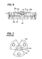
U.S. Patent No. 6,648,248 (Japanese Patent Publication No. 2001-304448 - Another technique has been proposed as illustrated in FIG. 7. As shown,
notches 110 are formed in the outer circumferential surface of anarmature 100.Communication grooves 130 are also included that establish communication between thenotches 110 and acentral recess 120 formed in the center of thearmature 100. Fluid drag produced when thearmature 100 is moved in fuel at high speed is thereby reduced. - However, this technique also suffers from certain disadvantages. Specifically, when the
armature 100 is formed of highly magnetic material (e.g. silicon steel) to enhance the solenoid response, the strength of thearmature 100 is relatively low. (For example, silicon steel has highly magnetic properties but it is a low-strength material). Also, thearmature 100 typically includes relatively thin-walled portions, such as between thenotches 110 and thecentral recess 120. Stress concentrations can develop at these thin-waHed portions. Therefore, it may be difficult to form thecommunication grooves 130 having a sufficient passage area in the thin-walled portions of thearmature 100 if it is made out of relatively low-strength magnetic material. - A solenoid valve for a fuel injection valve with an internal space is disclosed. Fuel is included in the internal space. The solenoid valve includes a magnet coil that forms an electromagnet when energized. The solenoid valve also includes a stator that is magnetized by the electromagnet. The solenoid further includes an armature provided in the internal space that is attracted to and moves toward the stator when the stator is magnetized. The armature includes an attracted surface that faces the stator, a second surface that is opposite the attracted surface, a recess provided in the attracted surface, at least one through hole that extends through the armature from the attracted surface to the second surface, and at least one communication groove that establishes communication between the recess and the at least one through hole.
-
- FIG. 1 is a sectional view of one embodiment of a solenoid valve for use in a fuel injection valve;
- FIG. 2 is a plan view of an armature for use in the solenoid valve of FIG. 1;
- FIG. 3 is a sectional view of a fuel injection valve with the solenoid valve of FIG 1;
- FIG. 4 is a plan view of another embodiment of an armature for use in the solenoid valve;
- FIG 5 is a sectional view of another embodiment of a solenoid valve;
- FIG 6 is a sectional view of another embodiment of an armature for use in a solenoid valve; and
- FIG 7 is a plan view of a conventional armature for use in a solenoid valve.
- Referring initially to FIGS. 1 - 3, one embodiment of a
solenoid valve 6 for afuel injection valve 1 is illustrated. In one embodiment, thefuel injection valve 1 is used for a common rail fuel injection system for diesel engines. As illustrated in FIG 3, thefuel injection valve 1 includes anozzle 2, anozzle holder 3, acontrol piston 4, anorifice plate 5, thesolenoid valve 6, and the like. - The
nozzle 2 is constructed of anozzle body 7 and aneedle 8 to be described in greater detail below. Thenozzle 2 is fixed to thenozzle holder 3 on an end opposite to the solenoid valve 6 (i.e., the lower end in FIG. 3) via aretaining nut 9. - The
nozzle body 7 includes aguide hole 10 that houses theneedle 8, afuel passage 11 that guides fuel into theguide hole 10, anozzle hole 12 through which fuel is injected when theneedle 8 is lifted, and the like. - The
guide hole 10 is drilled from the upper end face of thenozzle body 7 toward the tip of thenozzle body 7, and a conical seat face is formed at the end of theguide hole 10. Afuel sump 13 where the inside diameter is enlarged is formed at a midpoint in theguide hole 10. - The upstream end of the
fuel passage 11 is open at the upper end face of thenozzle body 7 and is in fluid communication with thefuel passage 14 formed in thenozzle holder 3. A downstream end of thefuel passage 11 is in fluid communication with thefuel sump 13. - The
needle 8 includes a slidingportion 8a that is slidably disposed in theguide hole 10 above thefuel sump 13 and ashank portion 8b that is disposed in theguide hole 10 beneath thefuel sump 13. A gap is included between the slidingportion 8a and theshank portion 8b. An outer diameter of theshank portion 8b is slightly smaller than that of the slidingportion 8a. Thus, an annular gap is ensured between the inner surface of theguide hole 10 and the outer surface of theshank portion 8b. (This annular gap is referred to as afuel passage 15.) A seat line is provided at the end of theshank portion 8b, and this seat line can seat on the seat face of thenozzle body 7 and blocks fluid communication between thefuel passage 15 and thenozzle hole 12. - The
nozzle holder 3 is provided with apiping joint 16. High-pressure fuel is supplied from a common rail through a fuel pipe (not shown) connected to thispiping joint 16. Abar filter 18 for filtering fuel is installed in theinternal passage 17 in thepiping joint 16. - The
nozzle holder 3 includes acylindrical hole 20 for housing thecontrol piston 4 and apressure pin 19. The above-mentionedfuel passage 14 is included in thenozzle holder 3 and guides high-pressure fuel from thepiping joint 16 to thenozzle 2. Thenozzle holder 3 also includes afuel passage 21 that guides the high-pressure fuel toward theorifice plate 5. Acylindrical wall portion 22 for installing thesolenoid valve 6 is provided at the upper end of thenozzle holder 3. - The
control piston 4 is slidably disposed in thecylindrical hole 20 in thenozzle holder 3. Oil pressure in apressure chamber 23, which will be described in greater detail, acts on the upper end face of thecontrol piston 4, - The
pressure pin 19 is connected to the lower part of the control piston 4 (i.e., the side opposite the pressure chamber), and the lower end face of thepressure pin 19 is abutted against the upper end face of theneedle 8. Thepressure pin 19 is moved integrally with thecontrol piston 4, Thepressure pin 19 presses theneedle 8 toward the valve closing direction (i,e., downward in FIG 3) due to biasing force from aspring 24 provided around the lower part of thepressure pin 19. - The
orifice plate 5 is disposed on the end face in thecylindrical wall portion 22 provided in thenozzle holder 3. Thevalve body 25 is also disposed in thecylindrical wall portion 22 above theorifice plate 5. Theorifice plate 5 is secured by threading and engaging thevalve body 25 with the inner circumferential surface of thecylindrical wall portion 22. Theorifice plate 5, as illustrated in FIG. 1 includes thepressure chamber 23 that communicates with thecylindrical hole 20 in thenozzle holder 3. Theorifice plate 5 also includes aninlet orifice 26 that communicates with thefuel passage 21 formed in thenozzle holder 3 and guides high-pressure fuel into thepressure chamber 23. Furthermore, theorifice plate 5 includes an outlet orifice 27 (i.e., a fuel passage) that discharges high-pressure fuel from thepressure chamber 23 when thesolenoid valve 6 is opened. - The
solenoid valve 6 includes amagnet coil 28 that forms an electromagnet when energized. Thesolenoid valve 6 also includes astator 29 that forms a magnetic circuit around themagnet coil 28. Furthermore, thesolenoid valve 6 includes anarmature 30 that is moved opposite to thestator 29. Also, thesolenoid valve 6 includes aball valve 31 that is moved with thearmature 30 to open and close theoutlet orifice 27. Thesolenoid valve 6 is fixed on thecylindrical wall portion 22 in thenozzle holder 3 via a retainingnut 32. - The
magnet coil 28 is wound on aresin bobbin 33 and is provided in thestator 29. Themagnet coil 28 is also at least partially encapsulated withresin material 34. - The
stator 29 is formed of a ferromagnetic material such as iron. When themagnet coil 28 is energized, thestator 29 is magnetized due to magnetic flux produced. Thestator 29 has acenter hole 35 that extends axially. Thecenter hole 35 is in fluid communication with thefuel discharge passage 37. Thefuel discharge passage 37 is provided in anend housing 36 provided on a side of thestator 29 opposite thearmature 30. - A
resin connector 38 is installed on theend housing 36. The terminal 39 is provided in theconnector 38, and themagnet coil 28 is electrically connected to the terminal 39 via ametal lead terminal 40. - In one embodiment, the
armature 30 is formed of a highly magnetic material, such as silicon steel. Thearmature 30 is provided in thevalve chamber 41 defined between thestator 29 and thevalve body 25 inside thecylindrical wall portion 22 of thenozzle holder 3. Further, thearmature 30 includes ashaft portion 42 that protrudes from a center portion away from thestator 29. Thearmature 30 includes an attractedsurface 30h that faces thestator 29 and a second surface 30j that is opposite to the attractedsurface 30h. Theshaft portion 42 is slidably provided in a slide hole in the center of thevalve body 25. - The
valve chamber 41 is filled with fuel, and communicates with thedischarge passage 37 through thecenter hole 35 in thestator 29. - The
spring 43 extends through thecenter hole 35 in thestator 29. Thearmature 30 is biased away from the stator 29 (i.e., downward in FIG 1) by thespring 43. When themagnet coil 28 is off, a predetermined gap is maintained between thearmature 30 and thestator 29. When themagnet coil 28 is energized and thestator 29 is thereby magnetized, thearmature 30 is attracted toward themagnetized stator 29. Then, thearmature 30 moves toward thestator 29 to abut against the end face of thestator 29. - A communicating
hole 44 is included in thevalve body 25 that communicates with the above-mentionedvalve chamber 41. Anoil passage 45 is also included in thevalve body 25 that communicates with theoutlet orifice 27 when theball valve 31 opens theoutlet orifice 27. Theoil passage 45 is in fluid communication to the side face of the communicatinghole 44. - The
ball valve 31 is held at the lower end of theshaft portion 42. When themagnet coil 28 is off, thearmature 30 is biased by thespring 43 away from thestator 29, and as a result, theball valve 31 closes theoutlet orifice 27 against the oil pressure in thepressure chamber 23. When themagnet coil 28 is energized, thearmature 30 is attracted toward themagnetized stator 29, and the ball valve is forced to open theoutlet orifice 27 by the oil pressure in thepressure chamber 23. Also, when themagnet coil 28 is off (i.e., when theball valve 31 has closed the outlet orifice 27), a relatively small gap is maintained between the surface of thearmature 30 and theplate 46. - As illustrated in FIG. 2, the
armature 30 includes acentral recess 30a in the axial center of the attractedsurface 30h (i.e., the surface of thearmature 30 facing thestator 29 and that is attracted by the magnetized stator 29). Thearmature 30 also includes a plurality of throughholes 30b that extend through thearmature 30 from the attractedsurface 30h to the second surface 30j of thearmature 30. Thearmature 30 further includes a plurality ofcommunication grooves 30c that extend radially on the attractedsurface 30h. Thecommunication grooves 30c establish communication between thecentral recess 30a and the throughholes 30b. Achamfer 30d (e.g., a chamfer of 45 degrees) is formed at the outer edge of thearmature 30 on the second side 30j. - The
central recess 30a extends axially from the attractedsurface 30h of thearmature 30 approximately half way through thearmature 30 toward the second surface 30j. Thecentral recess 30a of thearmature 30 is axially aligned and is in fluid communication with thecenter hole 35 of thestator 29. - The through
holes 30b are spaced equally from each other circumferentially. In the embodiment shown, there are three throughholes 30b spaced 120 degrees apart from each other circumferentially. When thearmature 30 abuts against thestator 29, the throughholes 30b are in fluid communication with thevalve chamber 41 through thechamfer 30d of thearmature 30. Thus, even when thearmature 30 abuts against thestator 29, a fluid passage exists between thevalve chamber 41, thechamfer 30d, the throughholes 30b, thecommunication grooves 30c, thecentral recess 30a, and thecenter hole 35. - The
communication grooves 30c are so formed that they have rectangular shape in a section taken perpendicular to the respective axis. Thecommunication grooves 30c establish fluid communication between the respective throughholes 30b and thecentral recess 30a. - A plurality of
notches 30e are also included in thearmature 30 between the throughholes 30b. Thenotches 30e extend radially inward from the outer periphery and are substantially V-shaped. In one embodiment, thenotches 30e are formed by cutting. Thenotches 30e are equally spaced circumferentially In the embodiment shown, there are threenotches 30e spaced at intervals of 120 degrees in the circumferential direction. - During operation, when the
magnet coil 28 is off, theball valve 31 closes theoutlet orifice 27. Therefore, theneedle 8 is biased in the valve closing direction because the oil pressure in thepressure chamber 23 and the force of thespring 24 is greater than oil pressure force that pushes up theneedle 8 in the valve opening direction. As a result, the seat line of theneedle 8 rests on the seat face to block communication between thefuel passage 15 and thenozzle hole 12, and fuel is not injected. - When the
magnet coil 28 is energized and the electromagnet is formed, thearmature 30 is attracted toward themagnetized stator 29 and moves toward thestator 29 against the biasing force of thespring 43. As a result, theball valve 31 opens theoutlet orifice 27 due to oil pressure in thepressure chamber 23. - Thus, the oil pressure in the
pressure chamber 23 is reduced because fluid passes through theoutlet orifice 27. Also, theneedle 8 moves toward the opening direction. Then, fuel supplied through thefuel passage 15 is injected from thenozzle hole 12. - When power is cut from the
magnet coil 28, the electromagnet stops functioning, thearmature 30 is biased away from thestator 29 by thespring 43, and theball valve 31 closes theoutlet orifice 27. Thus, the oil pressure in thepressure chamber 23 rises again. When the force that biases theneedle 8 in the valve closing direction thereby exceeds the oil pressure force that pushes up theneedle 8 in the valve opening direction, theneedle 8 moves toward the closing direction. Thus, the seat line of theneedle 8 rests on the seat face to block communication between thefuel passage 15 and thenozzle hole 12, and injection is thereby terminated. - The
solenoid valve 6 in this embodiment, used in thefuel injection valve 1 experiences resistance (i.e., fluid drag) due to thearmature 30 moving through fuel in thevalve chamber 41. As mentioned above, the attractedsurface 30h of thearmature 30 includes thecommunication grooves 30c that establish fluid communication between the throughholes 30b and thecentral recess 30a, and the second surface 30j of thearmature 30 includes thechamfer 30d on the peripheral edge. The throughholes 30b and thevalve chamber 41 communicate with each other through thechamfer 30d. As such, fuel can flow between thevalve chamber 41 and thecenter hole 35 in thestator 29 via the throughholes 30b. As a result, thearmature 30 experiences less fluid drag during movement. Thus response of thesolenoid valve 6 is improved. - In one embodiment, the
armature 30 is formed of silicon steel, a highly magnetic but relatively low strength material. Thearmature 30 can have improved response due to the silicon steel, but despite thecommunication grooves 30c, thearmature 30 is less likely to fracture or otherwise fail due to the construction described above. Unlike the prior art, thecommunication grooves 30c of the present embodiment establish fluid communication between the throughholes 30b and thecentral recess 30a. Thus, when external force (e.g. impact force produced when the armature collides with the stator 29) is applied to the armature 3C1, stress concentration is better distributed (i.e., stress concentrations are unlikely to be concentrated on thecommunication grooves 30c). Therefore, even with anarmature 30 made of silicon steel, the passage area (i.e., depth and groove width) of thecommunication grooves 30c is sufficiently large to reduce fluid drag. - Referring now to FIG 4, another embodiment of the
armature 30 is illustrated. In this embodiment, thearmature 30 includesfirst communication grooves 30c that establish fluid communication between thecentral recess 30a and the throughholes 30b. Thearmature 30 in this embodiment also includes second communication grooves 30f formed in the attractedsurface 30h. The second communication grooves establish fluid communication between thenotches 30e and thecentral recess 30a in thearmature 30. - Thus, in the embodiment of FIG. 4, two systems of passages are formed by forming the second communication grooves 30f. Fuel can flow between the
valve chamber 41 and thecenter hole 35 in thestator 29 through these passages. Therefore, it is possible to further reduce fluid drag produced when thearmature 30 moves to thereby obtain more stable response. - The depth, width, and the like of the second communication grooves 30f can be appropriately selected to the extent that required strength can be ensured in the
armature 30. - Referring now to FIG. 5, another embodiment of the
solenoid valve 6 is illustrated. In this embodiment, thesolenoid valve 6 includes anannular groove 34a formed in theresin material 34 that encapsulates themagnet coil 28. In this case, thenotches 30e and throughholes 30b formed in thearmature 30 communicate with each other through theannular groove 34a formed in theresin material 34. Therefore, fluid can flow between thevalve chamber 41 and thecenter hole 35 in thestator 29 via thenotches 30e as well as the throughholes 30b. - Referring now to FIG. 6, another embodiment of the
armature 30 is shown. In the embodiment shown, thearmature 30 includes astep 30g instead of thechamfer 30d described above. Accordingly, in the embodiment shown, the throughholes 30b and thevalve chamber 41 fluidly communicate with each other through thisstep 30g. - In the
fuel injection valve 1 described in the embodiment of FIGS. 1-3, thefuel discharge passage 37 is provided in theend housing 36 and communicates with thecenter hole 35 in thestator 29. In another embodiment, thedischarge passage 37 is provided in a component other than theend housing 36, for example, in thenozzle holder 3. - While only the selected embodiments have been chosen to illustrate the present invention, it will be apparent to those skilled in the art that various changes and modifications can be made therein without departing from the scope of the disclosure as defined in the appended claims. Furthermore, the foregoing description of the embodiments herein is provided for illustration only, and not for the purpose of limiting the disclosure as defined by the appended claims and their equivalents.
- A solenoid valve (6) for a fuel injection valve (1) with an internal space (41) is disclosed. Fuel is included in the internal space (41). The solenoid valve (6) includes a magnet coil (28) that forms an electromagnet when energized. The solenoid valve (6) also includes a stator (29) that is magnetized by the electromagnet. The solenoid (6) further includes an armature (30) provided in the internal space (41) that is attracted to and moves toward the stator (29) when the stator (29) is magnetized. The armature (30) includes an attracted surface (30h) that faces the stator (29), a second surface (30j) that is opposite the attracted surface (30h), a recess (30a) provided in the attracted surface (30h), at least one through hole (30b) that extends through the armature (30) from the attracted surface (30h) to the second surface (30j), and at least one communication groove (30c) that establishes communication between the recess (30a) and the at least one through hole (30b).
Claims (6)
- A solenoid valve (6) for a fuel injection valve (1) with an internal space (41), wherein fuel is included in the internal space (41), the solenoid valve (6) comprising:a magnet coil (28) that forms an electromagnet when energized;a stator (29) that is magnetized by the electromagnet; andan armature (30) provided in the internal space (41) that is attracted to and moves toward the stator (29) when the stator (29) is magnetized;wherein the armature (30) includes an attracted surface (30h) that faces the stator (29), a second surface (30j) that is opposite the attracted surface (30h), a recess (30a) provided in the attracted surface (30h), at least one through hole (30b) that extends through the armature (30) from the attracted surface (30h) to the second surface (30j), and at least one communication groove (30c) that establishes communication between the recess (30a) and the at least one through hole (30b).
- The solenoid valve (6) according to Claim 1, wherein the armature (30) includes a plurality of through holes (30b) spaced equally from each other circumferentially.
- The solenoid valve (6) according to Claim 1, wherein the armature (30) further comprises at least one of a chamfer (30d) and a step (30g) provided on a peripheral edge of the second surface (30j), and wherein the at least one through hole (30b) is in fluid communication with the internal space (41) through the at least one of the chamfer (30d) and the step (30g).
- The solenoid valve (6) according to Claim 1 wherein the armature (30) is formed of silicon steel.
- The solenoid valve (6) according to Claim 1, wherein the armature (30) further comprises at least one notch (30e) extending radially inward from an outer periphery of the armature (30).
- The solenoid valve (6) according to Claim 1, wherein the stator (29) includes a hole (35), and wherein the recess (30a) of the armature (30) is in fluid communication with the hole (35).
Applications Claiming Priority (1)
| Application Number | Priority Date | Filing Date | Title |
|---|---|---|---|
| JP2005251332A JP2007064364A (en) | 2005-08-31 | 2005-08-31 | Solenoid valve |
Publications (3)
| Publication Number | Publication Date |
|---|---|
| EP1760308A2 true EP1760308A2 (en) | 2007-03-07 |
| EP1760308A3 EP1760308A3 (en) | 2007-05-09 |
| EP1760308B1 EP1760308B1 (en) | 2010-01-27 |
Family
ID=37398705
Family Applications (1)
| Application Number | Title | Priority Date | Filing Date |
|---|---|---|---|
| EP06119888A Not-in-force EP1760308B1 (en) | 2005-08-31 | 2006-08-31 | Solenoid valve |
Country Status (5)
| Country | Link |
|---|---|
| US (1) | US7571891B2 (en) |
| EP (1) | EP1760308B1 (en) |
| JP (1) | JP2007064364A (en) |
| CN (1) | CN100476194C (en) |
| DE (1) | DE602006011989D1 (en) |
Cited By (4)
| Publication number | Priority date | Publication date | Assignee | Title |
|---|---|---|---|---|
| WO2008122452A1 (en) * | 2007-04-04 | 2008-10-16 | Robert Bosch Gmbh | Magnetic valve |
| WO2009138279A1 (en) * | 2008-05-16 | 2009-11-19 | Robert Bosch Gmbh | Solenoid valve having an armature slot configuration |
| EP2189648A1 (en) | 2008-11-19 | 2010-05-26 | Delphi Technologies Holding S.à.r.l. | Armature arrangement |
| US8839765B2 (en) | 2009-03-17 | 2014-09-23 | Robert Bosch Gmbh | Apparatus for injecting fuel into the combustion chamber of an internal combustion engine |
Families Citing this family (16)
| Publication number | Priority date | Publication date | Assignee | Title |
|---|---|---|---|---|
| JP4483940B2 (en) * | 2007-12-21 | 2010-06-16 | 株式会社デンソー | Fuel injection valve |
| JP2010174819A (en) | 2009-01-30 | 2010-08-12 | Denso Corp | Fuel injection valve |
| JP5040935B2 (en) | 2009-01-30 | 2012-10-03 | 株式会社デンソー | Fuel injection valve |
| JP2010174820A (en) | 2009-01-30 | 2010-08-12 | Denso Corp | Fuel injection valve |
| JP5293230B2 (en) | 2009-01-30 | 2013-09-18 | 株式会社デンソー | Fuel injection valve |
| US8729995B2 (en) * | 2010-12-20 | 2014-05-20 | Caterpillar Inc. | Solenoid actuator and fuel injector using same |
| US8701389B2 (en) * | 2011-12-06 | 2014-04-22 | Tenneco Automotive Operating Company Inc. | Reagent injector control system |
| JP2013174158A (en) * | 2012-02-24 | 2013-09-05 | Nabtesco Corp | Solenoid valve |
| US20150137014A1 (en) * | 2012-08-10 | 2015-05-21 | Toyota Jidosha Kabushiki Kaisha | Solenoid valve |
| CN103047060A (en) * | 2013-01-10 | 2013-04-17 | 无锡开普机械有限公司 | Controlled injection valve of electrical oil injector |
| JP6262482B2 (en) * | 2013-10-01 | 2018-01-17 | ナブテスコ株式会社 | Electromagnetic actuator |
| CN104074652B (en) * | 2014-06-30 | 2016-09-07 | 福建省莆田市中涵机动力有限公司 | The split type control valve of common-rail injector |
| JP6281978B2 (en) * | 2014-07-23 | 2018-02-21 | 日立オートモティブシステムズ株式会社 | solenoid valve |
| CN209164045U (en) * | 2018-11-19 | 2019-07-26 | 浙江锐韦机电科技有限公司 | Integrated pump valve mechanism |
| WO2022256661A1 (en) * | 2021-06-04 | 2022-12-08 | Cummins Inc. | Fuel injector devices, systems, and methods |
| JP2023018371A (en) * | 2021-07-27 | 2023-02-08 | 三菱重工エンジン&ターボチャージャ株式会社 | Solenoid device and solenoid valve of fuel injection device |
Citations (8)
| Publication number | Priority date | Publication date | Assignee | Title |
|---|---|---|---|---|
| EP0054108A2 (en) * | 1980-12-12 | 1982-06-23 | Robert Bosch Gmbh | Electromagnetically actuated valve, in particular a fuel injection valve for fuel injection systems |
| GB2178483A (en) * | 1985-07-31 | 1987-02-11 | Lucas Ind Plc | Fuel injector for I.C. engines |
| EP0304745A1 (en) * | 1987-08-25 | 1989-03-01 | WEBER S.r.l. | Fast solenoid valve, particularly a fuel injection pilot valve for diesel engines |
| WO1994019600A1 (en) * | 1993-02-16 | 1994-09-01 | Siemens Automotive Corporation | Fuel injector |
| US5636615A (en) * | 1995-02-21 | 1997-06-10 | Diesel Technology Company | Fuel pumping and injection systems |
| JPH09273460A (en) * | 1996-04-05 | 1997-10-21 | Mitsubishi Heavy Ind Ltd | Solid armature with groove |
| US20050139798A1 (en) * | 2003-12-24 | 2005-06-30 | Denso Corporation | Fuel injection valve having internal oil groove |
| JP2006322430A (en) * | 2005-05-20 | 2006-11-30 | Denso Corp | Fuel injection device |
Family Cites Families (7)
| Publication number | Priority date | Publication date | Assignee | Title |
|---|---|---|---|---|
| US5381965A (en) | 1993-02-16 | 1995-01-17 | Siemens Automotive L.P. | Fuel injector |
| US5570842A (en) * | 1994-12-02 | 1996-11-05 | Siemens Automotive Corporation | Low mass, through flow armature |
| JP3719461B2 (en) * | 1996-11-25 | 2005-11-24 | 株式会社デンソー | Accumulated fuel injection system |
| US6027037A (en) * | 1995-12-05 | 2000-02-22 | Denso Corporation | Accumulator fuel injection apparatus for internal combustion engine |
| IT1289794B1 (en) * | 1996-12-23 | 1998-10-16 | Elasis Sistema Ricerca Fiat | IMPROVEMENTS TO AN ELECTROMAGNETICALLY OPERATED DOSING VALVE FOR A FUEL INJECTOR. |
| US6036460A (en) * | 1998-06-29 | 2000-03-14 | Diesel Technology Company | Flexible armature for fuel injection system control valve |
| JP3631413B2 (en) | 2000-04-27 | 2005-03-23 | 株式会社デンソー | Solenoid valve and fuel injection device using the same |
-
2005
- 2005-08-31 JP JP2005251332A patent/JP2007064364A/en active Pending
-
2006
- 2006-08-30 CN CNB2006101288454A patent/CN100476194C/en not_active Expired - Fee Related
- 2006-08-31 DE DE602006011989T patent/DE602006011989D1/en active Active
- 2006-08-31 EP EP06119888A patent/EP1760308B1/en not_active Not-in-force
- 2006-08-31 US US11/513,012 patent/US7571891B2/en active Active
Patent Citations (8)
| Publication number | Priority date | Publication date | Assignee | Title |
|---|---|---|---|---|
| EP0054108A2 (en) * | 1980-12-12 | 1982-06-23 | Robert Bosch Gmbh | Electromagnetically actuated valve, in particular a fuel injection valve for fuel injection systems |
| GB2178483A (en) * | 1985-07-31 | 1987-02-11 | Lucas Ind Plc | Fuel injector for I.C. engines |
| EP0304745A1 (en) * | 1987-08-25 | 1989-03-01 | WEBER S.r.l. | Fast solenoid valve, particularly a fuel injection pilot valve for diesel engines |
| WO1994019600A1 (en) * | 1993-02-16 | 1994-09-01 | Siemens Automotive Corporation | Fuel injector |
| US5636615A (en) * | 1995-02-21 | 1997-06-10 | Diesel Technology Company | Fuel pumping and injection systems |
| JPH09273460A (en) * | 1996-04-05 | 1997-10-21 | Mitsubishi Heavy Ind Ltd | Solid armature with groove |
| US20050139798A1 (en) * | 2003-12-24 | 2005-06-30 | Denso Corporation | Fuel injection valve having internal oil groove |
| JP2006322430A (en) * | 2005-05-20 | 2006-11-30 | Denso Corp | Fuel injection device |
Cited By (5)
| Publication number | Priority date | Publication date | Assignee | Title |
|---|---|---|---|---|
| WO2008122452A1 (en) * | 2007-04-04 | 2008-10-16 | Robert Bosch Gmbh | Magnetic valve |
| WO2009138279A1 (en) * | 2008-05-16 | 2009-11-19 | Robert Bosch Gmbh | Solenoid valve having an armature slot configuration |
| EP2189648A1 (en) | 2008-11-19 | 2010-05-26 | Delphi Technologies Holding S.à.r.l. | Armature arrangement |
| US8839765B2 (en) | 2009-03-17 | 2014-09-23 | Robert Bosch Gmbh | Apparatus for injecting fuel into the combustion chamber of an internal combustion engine |
| AT508049B1 (en) * | 2009-03-17 | 2016-01-15 | Bosch Gmbh Robert | DEVICE FOR INJECTING FUEL IN THE COMBUSTION ENGINE OF AN INTERNAL COMBUSTION ENGINE |
Also Published As
| Publication number | Publication date |
|---|---|
| CN100476194C (en) | 2009-04-08 |
| DE602006011989D1 (en) | 2010-03-18 |
| CN1924343A (en) | 2007-03-07 |
| JP2007064364A (en) | 2007-03-15 |
| US7571891B2 (en) | 2009-08-11 |
| US20070057218A1 (en) | 2007-03-15 |
| EP1760308A3 (en) | 2007-05-09 |
| EP1760308B1 (en) | 2010-01-27 |
Similar Documents
| Publication | Publication Date | Title |
|---|---|---|
| EP1760308B1 (en) | Solenoid valve | |
| US7051960B2 (en) | Fuel injection valve | |
| CN107709749B (en) | Flow control valve and high-pressure fuel supply pump | |
| US6811105B2 (en) | Fuel injection nozzle | |
| WO2016163110A1 (en) | Fuel injection valve | |
| EP1150001B1 (en) | Solenoid valve and fuel injector using same | |
| JP2006017101A (en) | Fuel injection valve | |
| US20100102146A1 (en) | Fuel injection valve | |
| KR20020037068A (en) | Feul injection valve | |
| JPS61171876A (en) | Electromagnetically operated type fuel injection valve | |
| US8919372B2 (en) | Valve assembly for an injection valve and injection valve | |
| US7080819B2 (en) | Fuel injection valve having internal oil groove | |
| JP2010261396A (en) | Fuel injection valve | |
| JP4577654B2 (en) | Electromagnetic drive device and fuel injection valve using the same | |
| US6758419B2 (en) | Fuel injector | |
| WO2013047418A1 (en) | Solenoid actuator | |
| JPS63195377A (en) | Fuel injection valve | |
| JP2006299855A (en) | Fluid control valve | |
| GB2420829A (en) | A fuel injector regulator with combined initial injection rate and peak injection pressure regulation | |
| JP4135628B2 (en) | Fuel injection valve | |
| JP2007297962A (en) | Fuel injection nozzle | |
| JP2010174823A (en) | Fuel injection valve | |
| JP5093212B2 (en) | Fuel injection valve | |
| CN108779747B (en) | Fuel injection device | |
| JP2545894B2 (en) | Solenoid valve for fluid control |
Legal Events
| Date | Code | Title | Description |
|---|---|---|---|
| PUAI | Public reference made under article 153(3) epc to a published international application that has entered the european phase |
Free format text: ORIGINAL CODE: 0009012 |
|
| AK | Designated contracting states |
Kind code of ref document: A2 Designated state(s): AT BE BG CH CY CZ DE DK EE ES FI FR GB GR HU IE IS IT LI LT LU LV MC NL PL PT RO SE SI SK TR |
|
| AX | Request for extension of the european patent |
Extension state: AL BA HR MK YU |
|
| RIN1 | Information on inventor provided before grant (corrected) |
Inventor name: KUNO, KOHEI, DENSO CORPORATION |
|
| PUAL | Search report despatched |
Free format text: ORIGINAL CODE: 0009013 |
|
| AK | Designated contracting states |
Kind code of ref document: A3 Designated state(s): AT BE BG CH CY CZ DE DK EE ES FI FR GB GR HU IE IS IT LI LT LU LV MC NL PL PT RO SE SI SK TR |
|
| AX | Request for extension of the european patent |
Extension state: AL BA HR MK YU |
|
| 17P | Request for examination filed |
Effective date: 20070730 |
|
| 17Q | First examination report despatched |
Effective date: 20070928 |
|
| AKX | Designation fees paid | ||
| RBV | Designated contracting states (corrected) |
Designated state(s): DE FR GB |
|
| RBV | Designated contracting states (corrected) |
Designated state(s): DE FR GB |
|
| GRAP | Despatch of communication of intention to grant a patent |
Free format text: ORIGINAL CODE: EPIDOSNIGR1 |
|
| GRAS | Grant fee paid |
Free format text: ORIGINAL CODE: EPIDOSNIGR3 |
|
| GRAA | (expected) grant |
Free format text: ORIGINAL CODE: 0009210 |
|
| AK | Designated contracting states |
Kind code of ref document: B1 Designated state(s): DE FR GB |
|
| REG | Reference to a national code |
Ref country code: GB Ref legal event code: FG4D |
|
| REF | Corresponds to: |
Ref document number: 602006011989 Country of ref document: DE Date of ref document: 20100318 Kind code of ref document: P |
|
| PLBE | No opposition filed within time limit |
Free format text: ORIGINAL CODE: 0009261 |
|
| STAA | Information on the status of an ep patent application or granted ep patent |
Free format text: STATUS: NO OPPOSITION FILED WITHIN TIME LIMIT |
|
| REG | Reference to a national code |
Ref country code: GB Ref legal event code: 746 Effective date: 20101130 |
|
| 26N | No opposition filed |
Effective date: 20101028 |
|
| REG | Reference to a national code |
Ref country code: FR Ref legal event code: PLFP Year of fee payment: 10 |
|
| REG | Reference to a national code |
Ref country code: FR Ref legal event code: PLFP Year of fee payment: 11 |
|
| REG | Reference to a national code |
Ref country code: FR Ref legal event code: PLFP Year of fee payment: 12 |
|
| REG | Reference to a national code |
Ref country code: FR Ref legal event code: PLFP Year of fee payment: 13 |
|
| PGFP | Annual fee paid to national office [announced via postgrant information from national office to epo] |
Ref country code: GB Payment date: 20190821 Year of fee payment: 14 |
|
| PGFP | Annual fee paid to national office [announced via postgrant information from national office to epo] |
Ref country code: FR Payment date: 20200821 Year of fee payment: 15 |
|
| GBPC | Gb: european patent ceased through non-payment of renewal fee |
Effective date: 20200831 |
|
| PG25 | Lapsed in a contracting state [announced via postgrant information from national office to epo] |
Ref country code: GB Free format text: LAPSE BECAUSE OF NON-PAYMENT OF DUE FEES Effective date: 20200831 |
|
| PG25 | Lapsed in a contracting state [announced via postgrant information from national office to epo] |
Ref country code: FR Free format text: LAPSE BECAUSE OF NON-PAYMENT OF DUE FEES Effective date: 20210831 |
|
| PGFP | Annual fee paid to national office [announced via postgrant information from national office to epo] |
Ref country code: DE Payment date: 20220620 Year of fee payment: 17 |
|
| REG | Reference to a national code |
Ref country code: DE Ref legal event code: R119 Ref document number: 602006011989 Country of ref document: DE |
|
| PG25 | Lapsed in a contracting state [announced via postgrant information from national office to epo] |
Ref country code: DE Free format text: LAPSE BECAUSE OF NON-PAYMENT OF DUE FEES Effective date: 20240301 |