JP3631413B2 - Solenoid valve and fuel injection device using the same - Google Patents
Solenoid valve and fuel injection device using the same Download PDFInfo
- Publication number
- JP3631413B2 JP3631413B2 JP2000127397A JP2000127397A JP3631413B2 JP 3631413 B2 JP3631413 B2 JP 3631413B2 JP 2000127397 A JP2000127397 A JP 2000127397A JP 2000127397 A JP2000127397 A JP 2000127397A JP 3631413 B2 JP3631413 B2 JP 3631413B2
- Authority
- JP
- Japan
- Prior art keywords
- stator
- pressure receiving
- receiving means
- valve seat
- armature
- Prior art date
- Legal status (The legal status is an assumption and is not a legal conclusion. Google has not performed a legal analysis and makes no representation as to the accuracy of the status listed.)
- Expired - Fee Related
Links
Images


Classifications
-
- F—MECHANICAL ENGINEERING; LIGHTING; HEATING; WEAPONS; BLASTING
- F02—COMBUSTION ENGINES; HOT-GAS OR COMBUSTION-PRODUCT ENGINE PLANTS
- F02M—SUPPLYING COMBUSTION ENGINES IN GENERAL WITH COMBUSTIBLE MIXTURES OR CONSTITUENTS THEREOF
- F02M61/00—Fuel-injectors not provided for in groups F02M39/00 - F02M57/00 or F02M67/00
- F02M61/16—Details not provided for in, or of interest apart from, the apparatus of groups F02M61/02 - F02M61/14
- F02M61/168—Assembling; Disassembling; Manufacturing; Adjusting
-
- F—MECHANICAL ENGINEERING; LIGHTING; HEATING; WEAPONS; BLASTING
- F02—COMBUSTION ENGINES; HOT-GAS OR COMBUSTION-PRODUCT ENGINE PLANTS
- F02M—SUPPLYING COMBUSTION ENGINES IN GENERAL WITH COMBUSTIBLE MIXTURES OR CONSTITUENTS THEREOF
- F02M47/00—Fuel-injection apparatus operated cyclically with fuel-injection valves actuated by fluid pressure
- F02M47/02—Fuel-injection apparatus operated cyclically with fuel-injection valves actuated by fluid pressure of accumulator-injector type, i.e. having fuel pressure of accumulator tending to open, and fuel pressure in other chamber tending to close, injection valves and having means for periodically releasing that closing pressure
- F02M47/027—Electrically actuated valves draining the chamber to release the closing pressure
-
- F—MECHANICAL ENGINEERING; LIGHTING; HEATING; WEAPONS; BLASTING
- F02—COMBUSTION ENGINES; HOT-GAS OR COMBUSTION-PRODUCT ENGINE PLANTS
- F02M—SUPPLYING COMBUSTION ENGINES IN GENERAL WITH COMBUSTIBLE MIXTURES OR CONSTITUENTS THEREOF
- F02M63/00—Other fuel-injection apparatus having pertinent characteristics not provided for in groups F02M39/00 - F02M57/00 or F02M67/00; Details, component parts, or accessories of fuel-injection apparatus, not provided for in, or of interest apart from, the apparatus of groups F02M39/00 - F02M61/00 or F02M67/00; Combination of fuel pump with other devices, e.g. lubricating oil pump
- F02M63/0012—Valves
- F02M63/007—Details not provided for in, or of interest apart from, the apparatus of the groups F02M63/0014 - F02M63/0059
- F02M63/0078—Valve member details, e.g. special shape, hollow or fuel passages in the valve member
-
- F—MECHANICAL ENGINEERING; LIGHTING; HEATING; WEAPONS; BLASTING
- F02—COMBUSTION ENGINES; HOT-GAS OR COMBUSTION-PRODUCT ENGINE PLANTS
- F02M—SUPPLYING COMBUSTION ENGINES IN GENERAL WITH COMBUSTIBLE MIXTURES OR CONSTITUENTS THEREOF
- F02M2200/00—Details of fuel-injection apparatus, not otherwise provided for
- F02M2200/28—Details of throttles in fuel-injection apparatus
-
- F—MECHANICAL ENGINEERING; LIGHTING; HEATING; WEAPONS; BLASTING
- F02—COMBUSTION ENGINES; HOT-GAS OR COMBUSTION-PRODUCT ENGINE PLANTS
- F02M—SUPPLYING COMBUSTION ENGINES IN GENERAL WITH COMBUSTIBLE MIXTURES OR CONSTITUENTS THEREOF
- F02M2200/00—Details of fuel-injection apparatus, not otherwise provided for
- F02M2200/30—Fuel-injection apparatus having mechanical parts, the movement of which is damped
- F02M2200/306—Fuel-injection apparatus having mechanical parts, the movement of which is damped using mechanical means
-
- F—MECHANICAL ENGINEERING; LIGHTING; HEATING; WEAPONS; BLASTING
- F02—COMBUSTION ENGINES; HOT-GAS OR COMBUSTION-PRODUCT ENGINE PLANTS
- F02M—SUPPLYING COMBUSTION ENGINES IN GENERAL WITH COMBUSTIBLE MIXTURES OR CONSTITUENTS THEREOF
- F02M2200/00—Details of fuel-injection apparatus, not otherwise provided for
- F02M2200/90—Selection of particular materials
-
- F—MECHANICAL ENGINEERING; LIGHTING; HEATING; WEAPONS; BLASTING
- F02—COMBUSTION ENGINES; HOT-GAS OR COMBUSTION-PRODUCT ENGINE PLANTS
- F02M—SUPPLYING COMBUSTION ENGINES IN GENERAL WITH COMBUSTIBLE MIXTURES OR CONSTITUENTS THEREOF
- F02M63/00—Other fuel-injection apparatus having pertinent characteristics not provided for in groups F02M39/00 - F02M57/00 or F02M67/00; Details, component parts, or accessories of fuel-injection apparatus, not provided for in, or of interest apart from, the apparatus of groups F02M39/00 - F02M61/00 or F02M67/00; Combination of fuel pump with other devices, e.g. lubricating oil pump
- F02M63/0012—Valves
- F02M63/0014—Valves characterised by the valve actuating means
- F02M63/0015—Valves characterised by the valve actuating means electrical, e.g. using solenoid
-
- F—MECHANICAL ENGINEERING; LIGHTING; HEATING; WEAPONS; BLASTING
- F02—COMBUSTION ENGINES; HOT-GAS OR COMBUSTION-PRODUCT ENGINE PLANTS
- F02M—SUPPLYING COMBUSTION ENGINES IN GENERAL WITH COMBUSTIBLE MIXTURES OR CONSTITUENTS THEREOF
- F02M63/00—Other fuel-injection apparatus having pertinent characteristics not provided for in groups F02M39/00 - F02M57/00 or F02M67/00; Details, component parts, or accessories of fuel-injection apparatus, not provided for in, or of interest apart from, the apparatus of groups F02M39/00 - F02M61/00 or F02M67/00; Combination of fuel pump with other devices, e.g. lubricating oil pump
- F02M63/0012—Valves
- F02M63/0031—Valves characterized by the type of valves, e.g. special valve member details, valve seat details, valve housing details
- F02M63/004—Sliding valves, e.g. spool valves, i.e. whereby the closing member has a sliding movement along a seat for opening and closing
-
- F—MECHANICAL ENGINEERING; LIGHTING; HEATING; WEAPONS; BLASTING
- F02—COMBUSTION ENGINES; HOT-GAS OR COMBUSTION-PRODUCT ENGINE PLANTS
- F02M—SUPPLYING COMBUSTION ENGINES IN GENERAL WITH COMBUSTIBLE MIXTURES OR CONSTITUENTS THEREOF
- F02M63/00—Other fuel-injection apparatus having pertinent characteristics not provided for in groups F02M39/00 - F02M57/00 or F02M67/00; Details, component parts, or accessories of fuel-injection apparatus, not provided for in, or of interest apart from, the apparatus of groups F02M39/00 - F02M61/00 or F02M67/00; Combination of fuel pump with other devices, e.g. lubricating oil pump
- F02M63/0012—Valves
- F02M63/0031—Valves characterized by the type of valves, e.g. special valve member details, valve seat details, valve housing details
- F02M63/0043—Two-way valves
-
- Y—GENERAL TAGGING OF NEW TECHNOLOGICAL DEVELOPMENTS; GENERAL TAGGING OF CROSS-SECTIONAL TECHNOLOGIES SPANNING OVER SEVERAL SECTIONS OF THE IPC; TECHNICAL SUBJECTS COVERED BY FORMER USPC CROSS-REFERENCE ART COLLECTIONS [XRACs] AND DIGESTS
- Y10—TECHNICAL SUBJECTS COVERED BY FORMER USPC
- Y10T—TECHNICAL SUBJECTS COVERED BY FORMER US CLASSIFICATION
- Y10T137/00—Fluid handling
- Y10T137/8593—Systems
- Y10T137/86493—Multi-way valve unit
- Y10T137/86574—Supply and exhaust
- Y10T137/8667—Reciprocating valve
- Y10T137/86694—Piston valve
- Y10T137/86702—With internal flow passage
Description
【0001】
【発明の属する技術分野】
本発明は電磁弁及びそれを用いた燃料噴射装置に関する。
【0002】
【従来の技術】
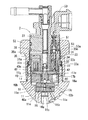
従来、電磁弁は内燃機関の燃料噴射装置等に幅広く用いられている。一般に、電磁弁は、流体通路が形成されているハウジングに対して位置決めされたステータにアーマチュアが吸引されることにより、アーマチュアと一体に移動する弁部材が弁孔を開放する。ステータをハウジングに対して位置決めすると弁部材の最大リフト量が決まる。このような電磁弁には、例えば特開平10−122086号公報に開示されているような電磁弁が知られている。図6に燃料噴射装置に用いられている従来の電磁弁の一例を示す。この電磁弁は燃料噴射ノズル(以下、インジェクタという。)のホルダボディ113に固定されているものである。制御弁部材106は、アーマチュア105に圧入固定されている。制御弁部材106は、軸受け110に往復移動自在に支持され、アーマチュア105がステータ104に吸引されることによりプレート111に形成されている弁孔108を開放する。軸受け110がホルダボディ113にねじ込まれていることにより、プレート111及びプレート112はホルダボディ113と軸受け110とに挟持されている。ステータ104は、A、Bの部位においてケース114に溶接されている。リテーニングナット102がホルダボディ113の筒状ねじ部107にねじ締めされることによりエンドボディ101とプレート110とによってケース114及びスペーサ109が挟持され、ステータ104が軸受け111に対して位置決めされている。これによりステータ104と弁孔108との間隔が固定され、制御弁部材106の最大リフト量が設定されている。
【0003】
【発明が解決しようとする課題】
しかし、図6に示す電磁弁によると、ステータ104をプレート111に対して位置決めするためには、ケース114とステータ104とを溶接しなければならない。したがって、ステータ104は耐熱性の高い部材でなければならない。一方、ステータ104の熱的な負荷をさけるため、エンドボディ101及びスペーサ109に直接ステータ104を当接させてステータ104を位置決めするとすれば、ステータ104にはリテーニングナット102を締め付けることによる圧縮応力が作用することになる。したがって、この場合には、ステータ104は適度な粘りと堅さを兼ね備えた部材でなければならない。このように、従来の電磁弁によると、ステータに用いることのできる素材が限定されることからステータの吸引力を向上させるにあたって不利であり、また、熱的な負荷又は圧縮応力によるステータの変形、破損の恐れがあった。
【0004】
本発明は、上記の問題を解決するために創作されたものであって、ステータに作用する荷重を低減する電磁弁及びそれを用いた燃料噴射装置を提供することを目的とする。
また、本発明の別の目的は、ステータとして用いうる素材の種類を広げる電磁弁及びそれを用いた燃料噴射装置を提供することを目的とする。
【0005】
【課題を解決するための手段】
本発明の請求項1記載の電磁弁によると、ステータを係止手段によって受圧手段に係止し、受圧手段を固定手段によってハウジングに押しつけることによってステータをハウジングに対して位置決めする。係止手段は、固定手段及びハウジングから受圧手段に作用する外力をステータに伝達することなしに受圧手段にステータを係止する。したがって、本発明の請求項1記載の電磁弁によると、ステータの組み付け時においてステータを位置決めして最大リフト量を設定するためにある種の外力を固定手段に加えてハウジングの所定位置に固定手段を係止した場合に、その外力によって受圧手段がハウジングに対して位置決めされる一方で、その外力が受圧手段から係止手段を介してステータに伝達されないため、ステータにかかる静的な荷重を低減することができる。尚、受圧手段は一部材であってもよく、またスペーサ等を有する多部材からなるものであってもよい。
【0006】
本発明の請求項2記載の電磁弁によると、係止手段は、ステータが係止される凹部を形成している挟持部材を有し、この挟持部材は、受圧手段の固定手段当接面より反ハウジング当接面側に受圧手段と一体に形成されている。ステータの組み付け時、受圧手段には固定手段当接面及びハウジング当接面に荷重がかかり、これにより受圧手段に圧縮応力が発生する。この圧縮応力により受圧手段が歪むとき、挟持部材は固定手段当接面より反ハウジング当接面側、すなわち受圧手段が固定手段から受ける外力の作用点よりその外力が作用する方向の反対側に設けられているため、挟持部材に荷重がかかることはない。したがって、ハウジングに受圧手段を押し付けてステータを位置決めすることによっては挟持部材の凹部に係止されるステータに静的な荷重がかからない。これにより、比較的低靱性の素材をステータに用いることができる。
【0007】
本発明の請求項3記載の電磁弁によると、受圧手段は、挟持部材の弁座側に挟持部材と一体に形成される筒体を有し、この筒体にハウジング及び固定手段によって挟持される位置決めフランジが形成されている。位置決めフランジがハウジング及び固定手段によって挟持されることにより固定手段に係止されたステータがハウジングに対して位置決めされる。尚、位置決めフランジは固定手段及びハウジングに対して直接当接して挟持されるものであってもよく、スペーサ等の別部材を挟んで間接的に挟持されるものであってもよい。
【0008】
本発明の請求項4記載の電磁弁によると、ステータは弁座側に近づくに従い外径が小さくなるテーパ部を形成している。挟持部材は、反弁座側縁部が径方向内側に折り曲げられている筒体であって、内壁に弁座に近づくに従い縮径しテーパ部に当接している円錐傾斜面を形成している。例えば、筒体の反弁座側縁部を塑性変形させることによって挟持部材に凹部を形成するとともに、この凹部にステータを係止することができる。したがって、溶接等の高熱処理を施すことなくステータをハウジングに対して位置決めすることができる。これにより、耐熱性の低い素材をステータに用いることができる。また、ステータはテーパ部において円錐傾斜面に当接しているため、例えば、筒体の反弁座側縁部が塑性変形することによってステータが円錐傾斜面に押しつけられて位置決めされている状態において、ステータの特定部位に応力が集中することを防止できる。
【0009】
本発明の請求項5記載の電磁弁によると、係止手段のストッパ部材は、アーマチュア又は制御弁部材に当接可能な筒体である。ストッパ部材には、ステータとともに挟持部に係止される緩衝フランジが反アーマチュア側に形成されている。ステータは、ストッパ部材の径方向外側に環状に設けられ反アーマチュア側端面が緩衝フランジに当接している。緩衝フランジを介してステータを挟持部材に押し当てることによりステータをハウジングに対して位置決めすることができる。したがって、ステータとストッパとを相互に固定することなくステータをハウジングに対して位置決めすることができる。また、制御弁部材がストッパ部材に衝突することによって制御弁部材の最大リフト量が規制される。ステータとストッパとを互いに固定する必要がないため、ストッパ部材に生ずる衝撃荷重がステータに伝達しない構成を採用することができる。したがって、比較的低靱性の素材をステータに用いることができる。
【0010】
本発明の請求項6記載の燃料噴射装置によると、ステータを係止手段によって受圧手段に係止し、受圧手段を固定手段によってノズル本体に押しつけることによってステータをノズル本体に対して位置決めする。係止手段は、固定手段及びノズル本体から受圧手段に作用する外力をステータに伝達することなしに受圧手段にステータを係止する。したがって、本発明の請求項6記載の燃料噴射装置によると、ステータの組み付け時においてステータを位置決めして最大リフト量を設定するためにある種の外力を固定手段に加えてノズル本体の所定位置に固定手段を係止した場合に、その外力によって受圧手段がノズル本体に対して位置決めされる一方で、その外力が受圧手段から係止手段を介してステータに伝達されないため、ステータにかかる静的な荷重を低減することができる。
【0011】
本発明の請求項7記載の燃料噴射装置によると、係止手段は、ステータが係止される凹部を形成している挟持部材を有し、この挟持部材は、受圧手段の固定手段当接面より反ノズル本体当接面側に受圧手段と一体に形成されている。ステータの組み付け時、受圧手段には固定手段当接面及びノズル本体当接面に荷重がかかり、これにより受圧手段に圧縮応力が発生する。この圧縮応力により受圧手段が歪むとき、挟持部材は固定手段当接面より反ノズル本体当接面側、すなわち受圧手段が固定手段から受ける外力の作用点よりその外力が作用する方向の反対側に設けられているため、挟持部材に荷重がかかることはない。したがって、ノズル本体に受圧手段を押し付けてステータを位置決めした状態において、挟持部材の凹部に係止されるステータに静的な荷重がかからない。これにより、比較的低靱性の素材をステータに用いることができる。
【0012】
本発明の請求項8記載の燃料噴射装置によると、受圧手段は、挟持部材の弁座側に挟持部材と一体に形成される筒体を有し、この筒体にノズル本体及び固定手段によって挟持される位置決めフランジが形成されている。位置決めフランジがノズル本体及び固定手段によって挟持されることにより固定手段に係止されたステータがハウジングに対して位置決めされる。
【0013】
本発明の請求項9記載の燃料噴射装置によると、ステータは弁座側に近づくに従い外径が小さくなるテーパ部を形成している。挟持部材は、反弁座側縁部が径方向内側に折り曲げられている筒体であって、内壁に弁座に近づくに従い縮径しテーパ部に当接している円錐傾斜面を形成している。例えば、筒体の反弁座側縁部を塑性変形させることによって挟持部材に凹部を形成するとともに、この凹部にステータを係止することができる。したがって、溶接等の高熱処理を施すことなくステータをノズル本体に対して位置決めすることができる。これにより、耐熱性の低い素材をステータに用いることができる。また、ステータはテーパ部において円錐傾斜面に当接しているため、例えば、筒体の反弁座側縁部が塑性変形することによってステータが円錐傾斜面に押しつけられて位置決めされている状態において、ステータの特定部位に応力が集中することを防止できる。
【0014】
本発明の請求項10記載の燃料噴射装置によると、係止手段のストッパ部材は、アーマチュア又は制御弁部材に当接可能な筒体である。ストッパ部材には、ステータとともに挟持部に係止される緩衝フランジが反アーマチュア側に形成されている。ステータは、ストッパ部材の径方向外側に環状に設けられ反アーマチュア側端面が緩衝フランジに当接している。緩衝フランジを介してステータを挟持部材に押し当てることによりステータをノズル本体に対して位置決めすることができる。したがって、ステータとストッパとを相互に固定することなくステータをノズル本体に対して位置決めすることができる。また、制御弁部材はストッパ部材に衝突することによって制御弁部材の最大リフト量が規制される。ステータとストッパとを互いに固定する必要がないため、ストッパ部材に生ずる衝撃荷重がステータに伝達しない構成を採用することができる。したがって、比較的低靱性の素材をステータに用いることができる。
【0015】
【発明の実施の形態】
以下、本発明の実施の形態を具体的に示す一実施例を図面に基づいて説明する。
本発明の一実施例による燃料噴射装置としてのインジェクタ1を図2に示す。インジェクタ1は図示しないエンジンのエンジンヘッドに挿入搭載され、エンジンの各気筒内に燃料を直接噴射するように構成されている。
【0016】
ホルダボディ11とノズルボディ12とはリテーニングナット14で締結されている。ホルダボディ11及びノズルボディ12は、特許請求の範囲に記載されたノズル本体を構成している。ホルダボディ11にはニードル収納孔11dが形成され、ノズルボディ12にはニードル収納孔12eが形成されている。ニードル収納孔11d、12eにはノズル弁部材20が収納されている。
【0017】
ホルダボディ11のインレット部11fには燃料流入通路11aが形成され、燃料流入通路11aにはバーフィルタ13が収納されている。燃料流入通路11aは燃料通路11bを通じてノズルボディ12に形成されている燃料通路12dと連通している。燃料通路12dは燃料溜まり12cにおいてニードル収納孔12eと連通している。ニードル収納孔12eは噴孔12bを通じて図示しないエンジンの気筒内空間に連通している。従って、図示しない燃料ポンプによって供給される燃料は、バーフィルタ13を通じてインジェクタ1の内部に導入され、燃料流入通路11a、燃料通路11b、12d、燃料溜まり12c、ニードル収納孔12e、噴孔12bを通じてエンジンの各気筒に至る。また、ホルダボディ11にはニードル収納孔11dに連通しているリーク通路11cが形成されている。
【0018】
ノズル弁部材20は、噴孔12b側からニードル20c、ロッド20b及び制御ピストン20aにより構成されている。
ニードル20cは噴孔12b側からシート部、小径部、テーパ部、大径部により構成されている。大径部はニードル収納孔12eの内壁に往復移動自在にかつほぼ液密に支持されている。テーパ部は燃料溜まり12cの燃料から図2の上向きに圧力を受けるように形成されている。小径部の外壁とニードル収納孔12eの内壁との間に周方向の隙間が形成されている。シート部は弁座12aに着座可能な形状である。ロッド20bは一方の端部がニードル20cに当接し、他方の端部が制御ピストン20aに当接している。ロッド20bの周囲に第一スプリング15が設けられ、第一スプリング15はロッド20bを介してニードル20cを弁座12aに付勢している。制御ピストン20aはニードル収納孔11dの内壁に往復移動自在にかつほぼ液密に支持されている。
【0019】
インジェクタ1の電磁弁に係る部分を示す。図1に示すように、ニードル収納孔11dの反ノズルボディ側に第一プレート16が設けられている。第一プレート16には、ニードル収納孔11dに連通している貫通孔16aと貫通孔16aと燃料流入通路11aとを連通しているオリフィス16bとが形成されている。制御ピストン20aの端部外壁、ニードル収納孔11dの内壁、及び貫通孔16aの内壁によって圧力室16cが形成されている。第一プレート16の反ニードルボディ側に第二プレート18が設けられている。
【0020】
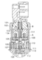
第二プレート18の反第一プレート側に第三プレート17が設けられている。第二プレート18の第三プレート側端面に弁座18aを平面状に形成している。第三プレート17の外周部は雄ねじを形成しており、第三プレート17がホルダボディ11の筒状ねじ部11gにねじ込まれることによって、第一プレート16及び第二プレート18が第三プレート17とホルダボディ11とに挟持されている。第三プレート17には流体通路としての貫通孔17a、17bが形成されている。貫通孔17aの内壁にブシュ60が圧入固定されている。ブシュ60は、薄肉かつ高硬度の円筒部材である。ブシュ60の端面と第二プレート18の端面との間に弁室が形成される。第二プレート18には圧力室16cと貫通孔17aとを連通している導出通路18bが形成されている。導出通路18bは特許請求の範囲に記載された流体通路を構成している。第一プレート16及び第二プレート18の外壁とホルダボディ11の内壁の間には周方向に隙間11eが形成され、この隙間はリーク通路11cと連通している。また、この隙間は、第三プレート17の第二プレート側端面に形成されている凹部17cを通じて貫通孔17a、17bに連通している。ホルダボディ11の筒状ねじ部11g、第二プレート18及び第三プレート17は、特許請求の範囲に記載された電磁弁のハウジングに相当するものである。また、ノズルボディ12、ホルダボディ11、及び第一プレート16は特許請求の範囲に記載されたノズル本体を構成している。
【0021】
ステータ31は受圧手段、挟持部材としての筒状のケース33に収納されている。ケース33の内径は、反弁座側で大きく、円錐傾斜面33bにおいて弁座18aに近づくに従い小さくなる。ケース33の外周には、円錐傾斜面33bより弁座側にフランジ33aが形成されている。固定手段としてのリテーニングナット52の内壁には位置決めフランジ33aに当接する段差面52a(図5参照)が形成されている。ホルダボディ11の端部に筒状に形成されている雄ねじ部11gにリテーニングナット52がねじ込まれることにより、位置決めフランジ33aが受圧手段としてのスペーサ19とともにリテーニングナット52と雄ねじ部11gとに挟持され、ケース33がホルダボディ11に固定されている。スペーサ19はその厚みによって制御弁部材40の最大リフト量を調整している環状板体である。尚、スペーサ19を設けることなく位置決めフランジ33aの厚みによって制御弁部材40のリフト量を調整してもよい。また、位置決めフランジ33aと雄ねじ部11gとの間にスペーサ19に代えて皿バネを設け、組み付け後にリテーニングナット52のねじ込み量を調整することにより制御弁部材40のリフト量を調整可能な構成とすることもできる。ケース33の反弁座側の開口部は係止手段としてのエンドボディ53によって閉塞され、薄肉部33cの縁部は径方向内側に折れ曲がりエンドボディ53の溝53aと嵌合している。エンドボディ53の外壁とリテーニングナット52の内壁とは径方向に対向し、軸方向に対向していない。
【0022】
エンドボディ53のアーマチュア側端面にストッパ部材35が当接している。ストッパ部材35は筒部35bと緩衝フランジ35aとからなる筒体である。筒部35bの径方向外側に環状のステータ31が設けられている。ステータ31の内壁面31aとストッパ部材35の外壁面との間には所定の周方向微小隙間が形成され、ステータ31とストッパ部材35とは直接的には結合されていない。ステータ31は緩衝フランジ35a側から大径部、テーパ部31b、小径部を形成している。大径部の端面31c(図4参照)は緩衝フランジ35aに当接し、大径部の外径と緩衝フランジ35aの外径とはほぼ等しい。ステータ31のテーパ部外壁面はケース33の円錐傾斜面33bに当接している。ステータ31の小径部にはボビン34とボビン34に巻回されたコイル32とが樹脂により固定されている。コイル32はコネクタ50に延伸しているターミナル51と電気的に接続されている。
【0023】
制御弁部材40は弁座18a側から球状部材40a、柱状部材40b、スプリング台座40cにより構成されている。球状部材40a、柱状部材40b、スプリング台座40cは互いに圧入等により結合されるものであっても一体に形成されるものであっても別体に形成されて互いに当接しているものであってもよい。球状部材40aの一部は第二プレート18に着座することにより導出通路18bを閉塞可能な平面状に形成されている。柱状部材40bはアーマチュア41に圧入され、ブシュ60の内壁によってアーマチュア41とともに往復移動自在に支持されている。アーマチュア41は第三プレート17とステータ31との間に設けられている。図3に示すように、アーマチュア41のステータ側端面中央部に突出部41aが形成されている。この突出部41aはフルリフト時においてエアギャップHを確保するためステータ側に50μm程度突出している。突出部41aはストッパ部材35の筒部35bと同軸上に形成され、突出部41aの端面と筒部35bの端面とは当接可能である。また、アーマチュア41の突出部41a以外の部分はステータ31に当接しない。
【0024】
図1に示すように、ストッパ35bに第二スプリング38が収納されている。第二スプリング38は、一端がエンドボディ53に圧入されているアジャスティングパイプ37に当接し、他端がスプリング台座40cに当接し、スプリング台座40c及び柱状部材40bを介して球状部材40aを第二プレート18側に付勢している。以上、インジェクタ1の構成を説明した。
【0025】
次に、図4、5に基づいて、ケース33、ステータ31、ストッパ35、エンドボディ53、リテーニングナット52がそれぞれどのように係合してホルダボディ11に結合されるかを説明する。
【0026】
ケース33にコイル32、ターミナル51等が固定されたステータ31が収納され、ステータ31のテーパ部31bがケース33の円錐傾斜面33bに当接し、ステータ31がケース33に対して同軸に位置決めされる。ステータ31にストッパ35が挿入され、ステータ31の端面31cにストッパ35の緩衝フランジ35aが当接し、ステータ31の内壁31aにストッパ35の筒部35bが支持され、ストッパ35がステータ31に対して同軸に位置決めされる。エンドボディ53に形成されている図示しない孔にターミナル51が挿入され、エンドボディ53と緩衝フランジ35aとを当接させる。
【0027】
この状態において、ケース33の薄肉部33cの縁部33dはエンドボディ53の溝53aに対応する位置に位置する。薄肉部33cの縁部33dを径方向内側に折り曲げてつぶし、ケース33とエンドボディ53とをかしめ固定する。薄肉部33cの縁部33dが折り曲げられると、エンドボディ53がケース33に挿入される方向(図4、5の下向き)に若干移動し、これにより緩衝フランジ35a及びステータ31がエンドボディ53と同じ方向に移動する。かしめ固定によってエンドボディ53から緩衝フランジ35aを介してステータ31に働く図4、5の下向きの外力により、ステータ31のテーパ部31bはケース33の円錐傾斜面33bに押し当てられ、ステータ31の軸方向位置がケース33に対して固定される。また、緩衝フランジ35aはエンドボディ53及びステータ31に挟持される。
【0028】
以上のようにしてステータ31、ストッパ35及びエンドボディ53が組み付けられたケース33は、スペーサ19を間に挟んでホルダボディ11の雄ねじ部11gに挿入される。ケース33及びエンドボディ53にリテーニングナット52をかぶせ、雄ねじ部11gにリテーニングナット52をねじ込むと、スペーサ19及び位置決めフランジ33aは、リテーニングナット52の段差面52a及び雄ねじ部11gの端面11fによって挟持される。
【0029】
リテーニングナット52を雄ねじ部11gにねじ込むことによってスペーサ19をはさんで位置決めフランジ33aが雄ねじ部11gの端面11fに押し当てられると、ケース33、ステータ31、ストッパ35及びエンドボディ53がホルダボディ11に対して位置決めされる。これにより、ホルダボディ11に固定された第二プレート18とステータ31との間隔が固定され、制御弁部材40の最大リフト量が設定される。
【0030】
次に、インジェクタ1の燃料噴射作動を説明する。
燃料は、図示しない燃料噴射ポンプから吐出され図示しない蓄圧管に送出される。蓄圧管の蓄圧室で所定の圧力に蓄圧された高圧燃料はインレット部11fに接続される図示しない配管を通じてインジェクタ1に供給される。また、図示しないECUにより、エンジンの運転条件に応じた駆動電流が生成され、コイル32に供給される。コイル32に駆動電流が流れるとステータ31に吸引力が発生する。この吸引力及び圧力室16cの燃料圧力から受ける力の合力である弁開方向の力が第二スプリング38の付勢力を上回るとステータ31にアーマチュア41が吸引される。アーマチュア41がステータ31に吸引されるとアーマチュア41とともに制御弁部材40は弁開方向すなわち図1の上方に移動し、アーマチュア41の突出部41aがストッパ35の筒部35bの端面に衝突することにより制御弁部材40の移動が制限されフルリフト状態となる。球状部材40aが導出通路18bを開放すると圧力室16cが導出通路18bを通じて低圧側の弁室に連通し、圧力室16cから弁室に燃料が導出される。弁室に導出された燃料は、貫通孔17a、17b、31a、アジャスティングパイプ37の内部空間等を通じて図示しない配管から燃料タンクに還流する。
【0031】
圧力室16cが弁室に連通すると、圧力室16cはオリフィス16bからの流入燃料量より導出通路18bからの流出燃料量が多いため燃料圧力が低下し始める。圧力室16cの燃料圧力が低下し、第一スプリング15の付勢荷重及び圧力室16cの燃料圧力から受ける力の合力である噴孔閉塞方向の力が燃料溜まり12cの燃料圧力から受ける噴孔開放方向の力より小さくなるとニードル20cは噴孔開放方向すなわち図1の上方に移動しはじめ弁座12aから離座する。ニードル20cが弁座12aから離座すると噴孔12bから燃料が噴射される。
【0032】
コイル32への駆動電流の供給が遮断されると、ステータ31の吸引力が消滅するため第二スプリング38は圧力室16cの燃料圧力から受ける力に抗って制御弁部材40を弁閉方向に移動させる。球状部材40aによって導出通路18bが閉塞された後にも圧力室16cにオリフィス16bから燃料が流入し続けるため、圧力室16cの燃料圧力は上昇し始める。圧力室16cの燃料圧力が上昇し、第一スプリング15の付勢荷重及び圧力室16cの燃料圧力から受ける力の合力である噴孔閉塞方向の力が燃料溜まり12cの燃料圧力から受ける噴孔開放方向の力より大きくなるとニードル20cは噴孔閉塞方向すなわち図1の下方に移動しはじめる。ニードル20cが弁座12aに着座すると燃料噴射が終了する。以上、インジェクタ1の燃料噴射作動を説明した。
【0033】
本発明の一実施例によるインジェクタ1によると、リテーニングナット52がねじ回されることにより位置決めフランジ33aに作用する外力は、端面33eと端面33fとの間に圧縮応力を生じさせるものの、薄肉部33cに実質的に及ぶことはない。これにより、リテーニングナット52がねじ回されることにより位置決めフランジ33aに作用する外力がステータ31に伝達されることはない。したがって、制御弁部材40が作動していない状態においてステータ31に作用する実質的な外力は、ケース33の縁部33dがかしめられていることによってストッパ35がノズルボディ側にステータ31を押す力と円錐傾斜面33bから受ける抗力のみである。ステータ31がエンドボディ53から受ける外力は軸方向に作用するところ、図5に示すように、テーパ部31bの外径及び円錐傾斜面33bにおけるケース33の内径はステータ31が押しつけられる方向、すなわちノズルボディ側にむかって小さくなっているため、ステータ31のテーパ部31bの特定部位に応力が集中しない。また、ケース33とステータ31とをかしめ固定することによりステータ31に作用する外力は、リテーニングナット52がねじ回されることにより位置決めフランジ33aに作用する外力に比べて極めて小さい。また、ステータ31は他のどの部材とも溶接されていないため、組み付け時にステータ31に熱負荷がかからない。
【0034】
また、本発明の一実施例によるインジェクタ1によると、ストッパ35の筒部35bの端面にアーマチュア41の突出部41aを当接させることにより制御弁部材40の最大リフト量を設定している。突出部41aが筒部35bに衝突することによりストッパ35に作用する衝撃荷重は、緩衝フランジ35aからエンドボディ53を介してケース33に伝達され、ケース33の位置決めフランジ33aからリテーニングナット52を介してホルダボディ11に伝達される。しかし、ストッパ35はステータ31に挿入されているだけで直接的にはいずれの部位においてもステータ31に結合されていないため、この衝撃荷重はステータ31に伝達されない。
【0035】
以上のことから、本発明の一実施例によるインジェクタ1によると、ステータ31にかかる静的な荷重が小さく、またステータ31に衝撃荷重がかからないため、比較的低靱性の素材をステータ31に用いることができる。また、ステータ31は他の部材と溶接されないため、耐熱性の低い素材をステータ31に用いることができる。したがって、ステータ31に用いる素材の種類を広げることができる。
【0036】
本実施例において、ケース33とエンドボディ53とをかしめ固定することにより、ケース33、ステータ31、ストッパ35及びエンドボディ53を互いに係止しているが、径方向にねじ込まれるねじ棒等によりケース33とエンドボディ53とを係止してもよい。
また、本実施例において、ストッパ35にアーマチュア41を当接させて制御弁部材40の最大リフト量を設定しているが、制御弁部材40の筒状部材40b等にフランジを設け、このフランジをホルダボディ11に対して位置決めされた部材に当接させることにより制御弁部材40の最大リフト量を設定してもよい。この場合、ストッパ35は不要となる。
また、本実施例において、ケース33とステータ31とは直接的に係合していないが、かしめ、ねじ止め等によりケース33にステータ31を直接的に係合させてもよい。
【図面の簡単な説明】
【図1】本発明の一実施例によるインジェクタの電磁弁に係る部分を示す断面図である。
【図2】本発明の一実施例によるインジェクタを示す断面図である。
【図3】本発明の一実施例に係るアーマチュアの形状を説明するための模式図である。
【図4】本発明の一実施例によるインジェクタの組み付け手順を説明するための部分断面図である。
【図5】本発明の一実施例によるインジェクタの組み付け手順を説明するための部分断面図である。
【図6】従来の電磁弁を示す断面図である。
【符号の説明】
1 インジェクタ(燃料噴射装置)
11 ホルダボディ(ノズル本体)
12 ノズルボディ(ノズル本体)
12b 噴孔
16c 圧力室
16 第一プレート(ノズル本体)
17 第三プレート(ハウジング)
17a、17b 貫通孔(流体通路)
18 第二プレート(ハウジング)
18a 弁座
18b 導出通路(流体通路)
19 スペーサ(受圧手段)
20 ノズル弁部材
31 ステータ
31b テーパ部
32 コイル
33 ケース
33a 位置決めフランジ(受圧手段)
33b 円錐傾斜面
33c 薄肉部(挟持部材)
35 ストッパ(ストッパ部材)
35a 緩衝フランジ
40 制御弁部材
41 アーマチュア
41a 突出部
50 コネクタ
51 ターミナル
52 リテーニングナット(固定手段)
53 エンドボディ(係止手段)[0001]
BACKGROUND OF THE INVENTION
The present invention relates to a solenoid valve and a fuel injection device using the same.
[0002]
[Prior art]
Conventionally, electromagnetic valves have been widely used in fuel injection devices for internal combustion engines. Generally, in a solenoid valve, when an armature is attracted to a stator positioned with respect to a housing in which a fluid passage is formed, a valve member that moves integrally with the armature opens a valve hole. When the stator is positioned with respect to the housing, the maximum lift amount of the valve member is determined. As such a solenoid valve, for example, a solenoid valve as disclosed in Japanese Patent Laid-Open No. 10-122086 is known. FIG. 6 shows an example of a conventional solenoid valve used in the fuel injection device. This electromagnetic valve is fixed to a
[0003]
[Problems to be solved by the invention]
However, according to the electromagnetic valve shown in FIG. 6, in order to position the
[0004]
The present invention has been created to solve the above-described problems, and an object thereof is to provide a solenoid valve that reduces a load acting on a stator and a fuel injection device using the solenoid valve.
Another object of the present invention is to provide a solenoid valve that expands the types of materials that can be used as a stator and a fuel injection device using the same.
[0005]
[Means for Solving the Problems]
According to the electromagnetic valve of the first aspect of the present invention, the stator is locked to the pressure receiving means by the locking means, and the pressure receiving means is pressed against the housing by the fixing means, thereby positioning the stator with respect to the housing. The locking means locks the stator to the pressure receiving means without transmitting external force acting on the pressure receiving means from the fixing means and the housing to the stator. Therefore, according to the solenoid valve according to
[0006]
According to the electromagnetic valve according to
[0007]
According to the electromagnetic valve according to claim 3 of the present invention, the pressure receiving means has a cylindrical body integrally formed with the clamping member on the valve seat side of the clamping member, and is clamped by the housing and the fixing means. A positioning flange is formed. By positioning the positioning flange between the housing and the fixing means, the stator locked to the fixing means is positioned with respect to the housing. The positioning flange may be held in direct contact with the fixing means and the housing, or may be held indirectly with another member such as a spacer interposed therebetween.
[0008]
According to the electromagnetic valve according to claim 4 of the present invention, the stator forms a tapered portion whose outer diameter decreases as it approaches the valve seat side. The clamping member is a cylindrical body whose counter-valve seat side edge is bent radially inward, and has a conical inclined surface that is reduced in diameter as it approaches the valve seat on the inner wall and abuts against the tapered portion. . For example, a concave portion can be formed in the holding member by plastically deforming the counter valve seat side edge portion of the cylindrical body, and the stator can be locked in the concave portion. Therefore, the stator can be positioned with respect to the housing without performing high heat treatment such as welding. Thereby, a raw material with low heat resistance can be used for a stator. In addition, since the stator is in contact with the conical inclined surface at the tapered portion, for example, in a state where the stator is pressed against the conical inclined surface by plastic deformation of the counter valve seat side edge portion of the cylindrical body, It is possible to prevent stress from concentrating on a specific portion of the stator.
[0009]
According to the electromagnetic valve of the fifth aspect of the present invention, the stopper member of the locking means is a cylindrical body that can contact the armature or the control valve member. The stopper member is formed with a shock-absorbing flange on the side opposite to the armature that is locked to the holding portion together with the stator. The stator is annularly provided on the radially outer side of the stopper member, and the end face on the side opposite to the armature is in contact with the buffer flange. The stator can be positioned with respect to the housing by pressing the stator against the holding member via the buffer flange. Therefore, the stator can be positioned with respect to the housing without fixing the stator and the stopper to each other. Further, the maximum lift amount of the control valve member is regulated by the control valve member colliding with the stopper member. Since it is not necessary to fix the stator and the stopper to each other, it is possible to adopt a configuration in which the impact load generated in the stopper member is not transmitted to the stator. Therefore, a relatively low toughness material can be used for the stator.
[0010]
According to the fuel injection device of the sixth aspect of the present invention, the stator is locked to the pressure receiving means by the locking means, and the stator is positioned with respect to the nozzle body by pressing the pressure receiving means against the nozzle body by the fixing means. The locking means locks the stator to the pressure receiving means without transmitting external force acting on the pressure receiving means from the fixing means and the nozzle body to the stator. Therefore, the present invention The fuel injection device according to claim 6. According to the above, when a certain external force is applied to the fixing means for positioning the stator and setting the maximum lift amount when the stator is assembled, and the fixing means is locked at a predetermined position of the nozzle body, the pressure is received by the external force. While the means is positioned with respect to the nozzle body, since the external force is not transmitted from the pressure receiving means to the stator via the locking means, the static load on the stator can be reduced.
[0011]
According to the fuel injection device of the seventh aspect of the present invention, the locking means has a holding member that forms a recess in which the stator is locked, and the holding member is a fixing means contact surface of the pressure receiving means. Further, it is formed integrally with the pressure receiving means on the non-nozzle body contact surface side. When the stator is assembled, a load is applied to the pressure receiving means on the contact surface of the fixing means and the contact surface of the nozzle body, thereby generating a compressive stress in the pressure receiving means. When the pressure receiving means is distorted by this compressive stress, the clamping member is located on the side opposite to the nozzle body abutting surface from the fixing means abutting surface, that is, on the side opposite to the direction in which the external force acts from the point of action of the external force received by the pressure receiving means from the fixing means. Since it is provided, a load is not applied to the clamping member. Therefore, in a state where the pressure receiving means is pressed against the nozzle body and the stator is positioned, no static load is applied to the stator that is locked in the concave portion of the holding member. Thereby, a relatively low toughness material can be used for the stator.
[0012]
According to the fuel injection device of the eighth aspect of the present invention, the pressure receiving means has a cylindrical body formed integrally with the clamping member on the valve seat side of the clamping member, and is sandwiched between the nozzle body and the fixing means. A positioning flange is formed. By positioning the positioning flange between the nozzle body and the fixing means, the stator locked to the fixing means is positioned with respect to the housing.
[0013]
According to the fuel injection device of the ninth aspect of the present invention, the stator forms the tapered portion whose outer diameter decreases as it approaches the valve seat side. The clamping member is a cylindrical body whose counter-valve seat side edge is bent radially inward, and has a conical inclined surface that is reduced in diameter as it approaches the valve seat on the inner wall and abuts against the tapered portion. . For example, a concave portion can be formed in the holding member by plastically deforming the counter valve seat side edge portion of the cylindrical body, and the stator can be locked in the concave portion. Therefore, the stator can be positioned with respect to the nozzle body without performing high heat treatment such as welding. Thereby, a raw material with low heat resistance can be used for a stator. In addition, since the stator is in contact with the conical inclined surface at the tapered portion, for example, in a state where the stator is pressed against the conical inclined surface by plastic deformation of the counter valve seat side edge portion of the cylindrical body, It is possible to prevent stress from concentrating on a specific portion of the stator.
[0014]
According to the fuel injection device of the tenth aspect of the present invention, the stopper member of the locking means is a cylindrical body that can contact the armature or the control valve member. The stopper member is formed with a shock-absorbing flange on the side opposite to the armature that is locked to the holding portion together with the stator. The stator is annularly provided on the radially outer side of the stopper member, and the end face on the side opposite to the armature is in contact with the buffer flange. The stator can be positioned with respect to the nozzle body by pressing the stator against the clamping member via the buffer flange. Therefore, the stator can be positioned with respect to the nozzle body without fixing the stator and the stopper to each other. Moreover, the maximum lift amount of the control valve member is regulated by the control valve member colliding with the stopper member. Since it is not necessary to fix the stator and the stopper to each other, it is possible to adopt a configuration in which the impact load generated in the stopper member is not transmitted to the stator. Therefore, a relatively low toughness material can be used for the stator.
[0015]
DETAILED DESCRIPTION OF THE INVENTION
DESCRIPTION OF THE PREFERRED EMBODIMENTS Hereinafter, an example specifically showing an embodiment of the present invention will be described with reference to the drawings.
FIG. 2 shows an
[0016]
The
[0017]
A
[0018]
The
The
[0019]
The part which concerns on the solenoid valve of the
[0020]
A
[0021]
The
[0022]
A
[0023]
The
[0024]
As shown in FIG. 1, the
[0025]
Next, how the
[0026]
A
[0027]
In this state, the
[0028]
The
[0029]
When the
[0030]
Next, the fuel injection operation of the
The fuel is discharged from a fuel injection pump (not shown) and sent to a pressure accumulating pipe (not shown). The high-pressure fuel stored at a predetermined pressure in the pressure storage chamber of the pressure storage pipe is supplied to the
[0031]
When the
[0032]
When the supply of the drive current to the
[0033]
According to the
[0034]
In addition, according to the
[0035]
From the above, according to the
[0036]
In this embodiment, the
Further, in this embodiment, the
In this embodiment, the
[Brief description of the drawings]
FIG. 1 is a cross-sectional view showing a portion related to an electromagnetic valve of an injector according to an embodiment of the present invention.
FIG. 2 is a cross-sectional view showing an injector according to an embodiment of the present invention.
FIG. 3 is a schematic diagram for explaining the shape of an armature according to an embodiment of the present invention.
FIG. 4 is a partial cross-sectional view for explaining an injector assembly procedure according to an embodiment of the present invention.
FIG. 5 is a partial cross-sectional view for explaining an injector assembly procedure according to an embodiment of the present invention.
FIG. 6 is a cross-sectional view showing a conventional solenoid valve.
[Explanation of symbols]
1 Injector (fuel injection device)
11 Holder body (nozzle body)
12 Nozzle body (nozzle body)
12b nozzle hole
16c pressure chamber
16 First plate (nozzle body)
17 Third plate (housing)
17a, 17b Through hole (fluid passage)
18 Second plate (housing)
18a Valve seat
18b Outlet passage (fluid passage)
19 Spacer (pressure receiving means)
20 Nozzle valve member
31 Stator
31b Taper part
32 coils
33 cases
33a Positioning flange (pressure receiving means)
33b Conical inclined surface
33c Thin part (clamping member)
35 Stopper (Stopper member)
35a Buffer flange
40 Control valve member
41 Armature
41a protrusion
50 connectors
51 terminal
52 Retaining nut (fixing means)
53 End body (locking means)
Claims (10)
前記弁座に着座すると前記流体通路を閉塞し、前記弁座から離座すると前記流体通路を開放する制御弁部材と、
前記制御弁部材の移動方向と同方向に移動するアーマチュアと、
前記アーマチュアを弁開方向に吸引するステータと、
前記ステータに電磁吸引力を発生させるコイルと、
前記ハウジングに当接している受圧手段と、
前記ハウジングに係止され前記受圧手段に当接し前記ハウジングに前記受圧手段を押し付けている固定手段と、
前記固定手段及び前記ハウジングから前記受圧手段に作用する外力を前記ステータに伝達することなしに前記受圧手段に前記ステータを係止する係止手段と、
を備えることを特徴とする電磁弁。A housing forming a fluid passage and a valve seat;
A control valve member that closes the fluid passage when seated on the valve seat and opens the fluid passage when separated from the valve seat;
An armature that moves in the same direction as the movement direction of the control valve member;
A stator for sucking the armature in the valve opening direction;
A coil for generating an electromagnetic attractive force in the stator;
Pressure receiving means in contact with the housing;
A fixing means that is locked to the housing and abuts against the pressure receiving means and presses the pressure receiving means against the housing;
Locking means for locking the stator to the pressure receiving means without transmitting external force acting on the pressure receiving means from the fixing means and the housing to the stator;
A solenoid valve comprising:
前記弁座に着座すると前記流体通路を閉塞し、前記弁座から離座すると前記流体通路を開放する制御弁部材と、
前記制御弁部材の移動方向と同方向に移動するアーマチュアと、前記アーマチュアを弁開方向に吸引するステータと、
前記ステータに電磁吸引力を発生させるコイルと、
前記ハウジングに当接している受圧手段と、前記ハウジングに係止され前記受圧手段に当接し前記ハウジングに前記受圧手段を押し付けている固定手段と、
前記受圧手段の固定手段当接面より反ハウジング当接面側に前記受圧手段と一体に形成され、前記ステータが係止される凹部を形成している挟持部材を有し、前記固定手段及び前記ハウジングから前記受圧手段に作用する外力を前記ステータに伝達することなしに前記受圧手段に前記ステータを係止する係止手段と、
を備えることを特徴とする電磁弁。 A housing forming a fluid passage and a valve seat;
A control valve member that closes the fluid passage when seated on the valve seat and opens the fluid passage when separated from the valve seat;
An armature that moves in the same direction as the movement direction of the control valve member; and a stator that sucks the armature in the valve opening direction;
A coil for generating an electromagnetic attractive force in the stator;
Pressure receiving means that is in contact with the housing; and fixing means that is locked to the housing and that is in contact with the pressure receiving means and presses the pressure receiving means against the housing;
Formed in the fixed unit said pressure receiving means integrally from the contact surface in the counter-housing contact surface side of said pressure receiving means, wherein the stator has a clamping member which forms a recess to be engaged, said fixing means and said Locking means for locking the stator to the pressure receiving means without transmitting external force acting on the pressure receiving means from a housing to the stator;
A solenoid valve comprising:
前記挟持部材は、反弁座側縁部が径方向内側に折り曲げられている筒体であって、内壁に前記弁座に近づくに従い縮径し前記テーパ部に当接している円錐傾斜面を形成していることを特徴とする請求項2又は3記載の電磁弁。The stator forms a tapered portion whose outer diameter decreases as it approaches the valve seat side,
The clamping member is a cylindrical body whose counter valve seat side edge is bent inward in the radial direction, and has a conical inclined surface that decreases in diameter as it approaches the valve seat on the inner wall and contacts the tapered portion. The solenoid valve according to claim 2 or 3, wherein the solenoid valve is provided.
前記ステータは、前記ストッパ部材の径方向外側に環状に設けられ反アーマチュア側端面が前記緩衝フランジに当接していることを特徴とする請求項2、3又は4記載の電磁弁。The locking means is a cylindrical stopper member that can come into contact with the armature or the control valve member, and a stopper flange that is locked to the holding portion together with the stator is formed on the side opposite to the armature Have
5. The solenoid valve according to claim 2, wherein the stator is provided annularly on the radially outer side of the stopper member, and an end face on the side opposite to the armature is in contact with the buffer flange.
前記ノズル弁部材を往復移動自在に支持し、前記ノズル弁部材に噴孔閉塞方向に燃料圧力を加える圧力室が形成されているノズル本体と、
前記圧力室から燃料を導出する流体通路及び弁座が形成されているハウジングと、
弁座に着座すると前記流体通路を閉塞し、前記弁座から離座すると前記流体通路を開放する制御弁部材と、
前記制御弁部材の移動方向と同方向に移動するアーマチュアと、
前記アーマチュアを弁開方向に吸引するステータと、
前記ステータに電磁吸引力を発生させるコイルと、
前記ノズル本体に当接している受圧手段と、
前記ノズル本体に係止され前記受圧手段に当接し前記ノズル本体に前記受圧手段を押し付けている固定手段と、
前記固定手段及び前記ノズル本体から前記受圧手段に作用する外力を前記ステータに伝達することなしに前記受圧手段に前記ステータを係止する係止手段と、
を備えることを特徴とする燃料噴射装置。A nozzle valve member for opening and closing the nozzle hole;
A nozzle body that supports the nozzle valve member so as to be reciprocally movable, and has a pressure chamber in which a fuel pressure is applied to the nozzle valve member in a nozzle hole closing direction;
A housing in which a fluid passage for leading fuel from the pressure chamber and a valve seat are formed;
A control valve member that closes the fluid passage when seated on a valve seat and opens the fluid passage when separated from the valve seat;
An armature that moves in the same direction as the movement direction of the control valve member;
A stator for sucking the armature in the valve opening direction;
A coil for generating an electromagnetic attractive force in the stator;
Pressure receiving means in contact with the nozzle body;
A fixing means that is locked to the nozzle body and abuts against the pressure receiving means and presses the pressure receiving means against the nozzle body;
A locking means for locking the stator to the pressure receiving means without transmitting external force acting on the pressure receiving means from the fixing means and the nozzle body to the stator;
A fuel injection device comprising:
前記ノズル弁部材を往復移動自在に支持し、前記ノズル弁部材に噴孔閉塞方向に燃料圧力を加える圧力室が形成されているノズル本体と、
前記圧力室から燃料を導出する流体通路及び弁座が形成されているハウジングと、
弁座に着座すると前記流体通路を閉塞し、前記弁座から離座すると前記流体通路を開放する制御弁部材と、
前記制御弁部材の移動方向と同方向に移動するアーマチュアと、
前記アーマチュアを弁開方向に吸引するステータと、
前記ステータに電磁吸引力を発生させるコイルと、
前記ノズル本体に当接している受圧手段と、
前記ノズル本体に係止され前記受圧手段に当接し前記ノズル本体に前記受圧手段を押し付けている固定手段と、
前記受圧手段の固定手段当接面より反ノズル本体当接面側に前記受圧手段と一体に形成され、前記ステータが係止される凹部を形成している挟持部材を有し、前記固定手段及び前記ノズル本体から前記受圧手段に作用する外力を前記ステータに伝達することなしに前記受圧手段に前記ステータを係止する係止手段と、
を備えることを特徴とする燃料噴射装置。 A nozzle valve member for opening and closing the nozzle hole;
A nozzle body that supports the nozzle valve member so as to be reciprocally movable, and has a pressure chamber in which a fuel pressure is applied to the nozzle valve member in a nozzle hole closing direction;
A housing in which a fluid passage for leading fuel from the pressure chamber and a valve seat are formed;
A control valve member that closes the fluid passage when seated on a valve seat and opens the fluid passage when separated from the valve seat;
An armature that moves in the same direction as the movement direction of the control valve member;
A stator for sucking the armature in the valve opening direction;
A coil for generating an electromagnetic attractive force in the stator;
Pressure receiving means in contact with the nozzle body;
A fixing means that is locked to the nozzle body and abuts against the pressure receiving means and presses the pressure receiving means against the nozzle body;
Wherein formed on the fixing means the pressure receiving means and integrally from the opposite to the nozzle body facing side abutment surface of the pressure receiving means has a clamping member, wherein the stator is a recess to be engaged, said locking means and Locking means for locking the stator to the pressure receiving means without transmitting external force acting on the pressure receiving means from the nozzle body to the stator;
A fuel injection device comprising:
前記挟持部材は、反弁座側縁部が径方向内側に折り曲げられている筒体であって、内壁に前記弁座に近づくに従い縮径し前記テーパ部に当接している円錐傾斜面を形成していることを特徴とする請求項7又は8記載の燃料噴射装置。The stator forms a tapered portion whose outer diameter decreases as it approaches the valve seat side,
The clamping member is a cylindrical body whose counter valve seat side edge is bent inward in the radial direction, and has a conical inclined surface that decreases in diameter as it approaches the valve seat on the inner wall and contacts the tapered portion. The fuel injection device according to claim 7 or 8, wherein the fuel injection device is provided.
前記ステータは、前記ストッパ部材の径方向外側に環状に設けられ反アーマチュア側端面が前記緩衝フランジに当接していることを特徴とする請求項7、8又は9記載の燃料噴射装置。The locking means is a cylindrical stopper member that can come into contact with the armature or the control valve member, and a stopper flange that is locked to the clamping member together with the stator is formed on the side opposite to the armature Have
10. The fuel injection device according to claim 7, wherein the stator is provided in an annular shape on an outer side in the radial direction of the stopper member, and an end face on the side opposite to the armature is in contact with the buffer flange.
Priority Applications (4)
| Application Number | Priority Date | Filing Date | Title |
|---|---|---|---|
| JP2000127397A JP3631413B2 (en) | 2000-04-27 | 2000-04-27 | Solenoid valve and fuel injection device using the same |
| US09/838,569 US6648248B2 (en) | 2000-04-27 | 2001-04-20 | Solenoid valve and fuel injector using same |
| DE60112985T DE60112985T2 (en) | 2000-04-27 | 2001-04-26 | Solenoid valve and this using fuel injector |
| EP01110394A EP1150001B1 (en) | 2000-04-27 | 2001-04-26 | Solenoid valve and fuel injector using same |
Applications Claiming Priority (1)
| Application Number | Priority Date | Filing Date | Title |
|---|---|---|---|
| JP2000127397A JP3631413B2 (en) | 2000-04-27 | 2000-04-27 | Solenoid valve and fuel injection device using the same |
Publications (2)
| Publication Number | Publication Date |
|---|---|
| JP2001304448A JP2001304448A (en) | 2001-10-31 |
| JP3631413B2 true JP3631413B2 (en) | 2005-03-23 |
Family
ID=18636995
Family Applications (1)
| Application Number | Title | Priority Date | Filing Date |
|---|---|---|---|
| JP2000127397A Expired - Fee Related JP3631413B2 (en) | 2000-04-27 | 2000-04-27 | Solenoid valve and fuel injection device using the same |
Country Status (4)
| Country | Link |
|---|---|
| US (1) | US6648248B2 (en) |
| EP (1) | EP1150001B1 (en) |
| JP (1) | JP3631413B2 (en) |
| DE (1) | DE60112985T2 (en) |
Families Citing this family (21)
| Publication number | Priority date | Publication date | Assignee | Title |
|---|---|---|---|---|
| KR100597760B1 (en) * | 2002-03-15 | 2006-07-05 | 봇슈 가부시키가이샤 | Fuel injector |
| DE10240879A1 (en) * | 2002-09-04 | 2004-03-18 | Robert Bosch Gmbh | Fuel injector for injection system for internal combustion engines has injection valve component guided in central bore of injector body inside pair-ground section, and valve element closing central bore is in disc-form |
| DE10304742A1 (en) * | 2003-02-06 | 2004-08-19 | Robert Bosch Gmbh | Fuel injection device for an internal combustion engine |
| JP2005105923A (en) * | 2003-09-30 | 2005-04-21 | Bosch Automotive Systems Corp | Fuel injection valve |
| DE102004047179A1 (en) * | 2004-09-29 | 2006-03-30 | Robert Bosch Gmbh | Fuel injector |
| US7497203B2 (en) | 2005-08-03 | 2009-03-03 | Caterpillar Inc. | Avoidance of spark damage on valve members |
| JP2007064364A (en) * | 2005-08-31 | 2007-03-15 | Denso Corp | Solenoid valve |
| US20070138324A1 (en) * | 2005-12-20 | 2007-06-21 | Ibrahim Daniel R | Armature assembly with improved alignment capability |
| JP2007192079A (en) * | 2006-01-18 | 2007-08-02 | Denso Corp | Fuel injection valve |
| JP2008057524A (en) * | 2006-08-01 | 2008-03-13 | Denso Corp | Injector |
| US8002206B2 (en) * | 2006-12-29 | 2011-08-23 | Caterpillar Inc. | Avoidance of spark damage on valve members |
| US8083206B2 (en) * | 2008-07-08 | 2011-12-27 | Caterpillar Inc. | Precision ground armature assembly for solenoid actuator and fuel injector using same |
| DE102009028979A1 (en) * | 2009-08-28 | 2011-03-03 | Robert Bosch Gmbh | Fuel injector for an internal combustion engine |
| JP5093212B2 (en) * | 2009-10-23 | 2012-12-12 | 株式会社デンソー | Fuel injection valve |
| JP5218487B2 (en) * | 2009-12-04 | 2013-06-26 | 株式会社デンソー | Fuel injection valve |
| CN104066964B (en) * | 2011-11-01 | 2017-06-20 | 康明斯公司 | Fuel injector with injection control valve cylinder |
| US9651011B2 (en) * | 2012-05-08 | 2017-05-16 | Continental Automotive Gmbh | Valve assembly for an injection valve and injection valve |
| JP6050781B2 (en) * | 2014-05-13 | 2016-12-21 | 株式会社ニッキ | Gas fuel regulator |
| JP6729288B2 (en) * | 2016-10-21 | 2020-07-22 | 株式会社デンソー | Electromagnetic actuator |
| JP6810615B2 (en) * | 2017-01-11 | 2021-01-06 | ボッシュ株式会社 | Manufacturing method of fuel injection valve |
| GB2564654A (en) * | 2017-07-17 | 2019-01-23 | Delphi Int Operations Luxembourg Sarl | High pressure fuel pump |
Family Cites Families (8)
| Publication number | Priority date | Publication date | Assignee | Title |
|---|---|---|---|---|
| EP0571001B1 (en) * | 1987-12-02 | 1997-09-24 | Ganser-Hydromag Ag | Electronically controlled fuel injector |
| IT1257958B (en) * | 1992-12-29 | 1996-02-19 | Mario Ricco | ELECTROMAGNETIC CONTROL DOSING VALVE REGISTRATION DEVICE, FOR A FUEL INJECTOR |
| IT227711Y1 (en) * | 1992-12-29 | 1997-12-15 | Elasis Sistema Ricerca Fiat | ELECTROMAGNETIC CONTROLLED METERING VALVE FOR A FUEL INJECTOR |
| DE19639117A1 (en) * | 1996-09-24 | 1998-03-26 | Bosch Gmbh Robert | Fuel injector |
| JPH10122086A (en) | 1996-10-14 | 1998-05-12 | Denso Corp | Accumulative fuel injector |
| DE19708104A1 (en) * | 1997-02-28 | 1998-09-03 | Bosch Gmbh Robert | magnetic valve |
| US6237570B1 (en) * | 1997-10-09 | 2001-05-29 | Denso Corporation | Accumulator fuel injection apparatus |
| US5975139A (en) * | 1998-01-09 | 1999-11-02 | Caterpillar Inc. | Servo control valve for a hydraulically-actuated device |
-
2000
- 2000-04-27 JP JP2000127397A patent/JP3631413B2/en not_active Expired - Fee Related
-
2001
- 2001-04-20 US US09/838,569 patent/US6648248B2/en not_active Expired - Fee Related
- 2001-04-26 DE DE60112985T patent/DE60112985T2/en not_active Expired - Lifetime
- 2001-04-26 EP EP01110394A patent/EP1150001B1/en not_active Expired - Lifetime
Also Published As
| Publication number | Publication date |
|---|---|
| DE60112985T2 (en) | 2006-05-18 |
| US6648248B2 (en) | 2003-11-18 |
| EP1150001B1 (en) | 2005-08-31 |
| EP1150001A3 (en) | 2003-09-17 |
| US20020020769A1 (en) | 2002-02-21 |
| EP1150001A2 (en) | 2001-10-31 |
| JP2001304448A (en) | 2001-10-31 |
| DE60112985D1 (en) | 2005-10-06 |
Similar Documents
| Publication | Publication Date | Title |
|---|---|---|
| JP3631413B2 (en) | Solenoid valve and fuel injection device using the same | |
| JP4277158B2 (en) | Solenoid valve and fuel injection device using the same | |
| JP4188845B2 (en) | Adjustable pressure regulating valve for fuel injection system | |
| JP3802702B2 (en) | Mounting structure of seal member in electromagnetic fuel injection valve | |
| JP2004516425A (en) | Solenoid valve for controlling the injection valve of an internal combustion engine | |
| JP2001295727A (en) | High pressure pump | |
| US20050161537A1 (en) | Fuel injection valve | |
| JP2001295720A (en) | Solenoid valve and fuel supply device using it | |
| JP4260228B2 (en) | Fuel injection valve for internal combustion engine | |
| EP1674715A1 (en) | Injector | |
| US8092198B2 (en) | Fuel pump for internal combustion engine | |
| US7063077B2 (en) | Electromagnetic valve-actuated control module for controlling fluid in injection systems | |
| JP2003028022A (en) | Fuel injection valve | |
| JP2003534492A (en) | Fuel injection valve | |
| US6915960B2 (en) | Fuel-injection and a method for setting the same | |
| JP4087817B2 (en) | Fuel injection valve | |
| JP2002371939A (en) | Magnet valve for controlling injection nozzle of internal combustion engine | |
| JP4669852B2 (en) | Electromagnetic fuel injection valve | |
| JP5316140B2 (en) | Solenoid valve device | |
| JP4241599B2 (en) | Fuel injection valve | |
| JP4178408B2 (en) | Fuel injection valve and manufacturing method thereof | |
| JP3932065B2 (en) | Solenoid valve and manufacturing method thereof | |
| US20030079714A1 (en) | Fuel injection valve | |
| JP2024012239A (en) | injector | |
| JP2006242108A (en) | Solenoid valve and fuel injection device using the same |
Legal Events
| Date | Code | Title | Description |
|---|---|---|---|
| A977 | Report on retrieval |
Free format text: JAPANESE INTERMEDIATE CODE: A971007 Effective date: 20040812 |
|
| A131 | Notification of reasons for refusal |
Free format text: JAPANESE INTERMEDIATE CODE: A131 Effective date: 20040820 |
|
| A521 | Written amendment |
Free format text: JAPANESE INTERMEDIATE CODE: A523 Effective date: 20041018 |
|
| TRDD | Decision of grant or rejection written | ||
| A01 | Written decision to grant a patent or to grant a registration (utility model) |
Free format text: JAPANESE INTERMEDIATE CODE: A01 Effective date: 20041119 |
|
| A61 | First payment of annual fees (during grant procedure) |
Free format text: JAPANESE INTERMEDIATE CODE: A61 Effective date: 20041216 |
|
| R150 | Certificate of patent or registration of utility model |
Ref document number: 3631413 Country of ref document: JP Free format text: JAPANESE INTERMEDIATE CODE: R150 Free format text: JAPANESE INTERMEDIATE CODE: R150 |
|
| FPAY | Renewal fee payment (event date is renewal date of database) |
Free format text: PAYMENT UNTIL: 20071224 Year of fee payment: 3 |
|
| FPAY | Renewal fee payment (event date is renewal date of database) |
Free format text: PAYMENT UNTIL: 20101224 Year of fee payment: 6 |
|
| FPAY | Renewal fee payment (event date is renewal date of database) |
Free format text: PAYMENT UNTIL: 20111224 Year of fee payment: 7 |
|
| FPAY | Renewal fee payment (event date is renewal date of database) |
Free format text: PAYMENT UNTIL: 20121224 Year of fee payment: 8 |
|
| FPAY | Renewal fee payment (event date is renewal date of database) |
Free format text: PAYMENT UNTIL: 20131224 Year of fee payment: 9 |
|
| R250 | Receipt of annual fees |
Free format text: JAPANESE INTERMEDIATE CODE: R250 |
|
| R250 | Receipt of annual fees |
Free format text: JAPANESE INTERMEDIATE CODE: R250 |
|
| R250 | Receipt of annual fees |
Free format text: JAPANESE INTERMEDIATE CODE: R250 |
|
| R250 | Receipt of annual fees |
Free format text: JAPANESE INTERMEDIATE CODE: R250 |
|
| R250 | Receipt of annual fees |
Free format text: JAPANESE INTERMEDIATE CODE: R250 |
|
| R250 | Receipt of annual fees |
Free format text: JAPANESE INTERMEDIATE CODE: R250 |
|
| LAPS | Cancellation because of no payment of annual fees |