EP1760183B2 - Waschmachine und/oder Trockner mit einem versteiften Dämpferlager - Google Patents
Waschmachine und/oder Trockner mit einem versteiften Dämpferlager Download PDFInfo
- Publication number
- EP1760183B2 EP1760183B2 EP06119691.1A EP06119691A EP1760183B2 EP 1760183 B2 EP1760183 B2 EP 1760183B2 EP 06119691 A EP06119691 A EP 06119691A EP 1760183 B2 EP1760183 B2 EP 1760183B2
- Authority
- EP
- European Patent Office
- Prior art keywords
- machine according
- bottom plate
- damper
- washing machine
- fixing
- Prior art date
- Legal status (The legal status is an assumption and is not a legal conclusion. Google has not performed a legal analysis and makes no representation as to the accuracy of the status listed.)
- Active
Links
Images


Classifications
-
- D—TEXTILES; PAPER
- D06—TREATMENT OF TEXTILES OR THE LIKE; LAUNDERING; FLEXIBLE MATERIALS NOT OTHERWISE PROVIDED FOR
- D06F—LAUNDERING, DRYING, IRONING, PRESSING OR FOLDING TEXTILE ARTICLES
- D06F37/00—Details specific to washing machines covered by groups D06F21/00 - D06F25/00
- D06F37/20—Mountings, e.g. resilient mountings, for the rotary receptacle, motor, tub or casing; Preventing or damping vibrations
- D06F37/22—Mountings, e.g. resilient mountings, for the rotary receptacle, motor, tub or casing; Preventing or damping vibrations in machines with a receptacle rotating or oscillating about a horizontal axis
-
- D—TEXTILES; PAPER
- D06—TREATMENT OF TEXTILES OR THE LIKE; LAUNDERING; FLEXIBLE MATERIALS NOT OTHERWISE PROVIDED FOR
- D06F—LAUNDERING, DRYING, IRONING, PRESSING OR FOLDING TEXTILE ARTICLES
- D06F39/00—Details of washing machines not specific to a single type of machines covered by groups D06F9/00 - D06F27/00
- D06F39/12—Casings; Tubs
-
- D—TEXTILES; PAPER
- D06—TREATMENT OF TEXTILES OR THE LIKE; LAUNDERING; FLEXIBLE MATERIALS NOT OTHERWISE PROVIDED FOR
- D06F—LAUNDERING, DRYING, IRONING, PRESSING OR FOLDING TEXTILE ARTICLES
- D06F37/00—Details specific to washing machines covered by groups D06F21/00 - D06F25/00
- D06F37/20—Mountings, e.g. resilient mountings, for the rotary receptacle, motor, tub or casing; Preventing or damping vibrations
-
- F—MECHANICAL ENGINEERING; LIGHTING; HEATING; WEAPONS; BLASTING
- F16—ENGINEERING ELEMENTS AND UNITS; GENERAL MEASURES FOR PRODUCING AND MAINTAINING EFFECTIVE FUNCTIONING OF MACHINES OR INSTALLATIONS; THERMAL INSULATION IN GENERAL
- F16C—SHAFTS; FLEXIBLE SHAFTS; ELEMENTS OR CRANKSHAFT MECHANISMS; ROTARY BODIES OTHER THAN GEARING ELEMENTS; BEARINGS
- F16C11/00—Pivots; Pivotal connections
- F16C11/04—Pivotal connections
- F16C11/045—Pivotal connections with at least a pair of arms pivoting relatively to at least one other arm, all arms being mounted on one pin
-
- F—MECHANICAL ENGINEERING; LIGHTING; HEATING; WEAPONS; BLASTING
- F16—ENGINEERING ELEMENTS AND UNITS; GENERAL MEASURES FOR PRODUCING AND MAINTAINING EFFECTIVE FUNCTIONING OF MACHINES OR INSTALLATIONS; THERMAL INSULATION IN GENERAL
- F16C—SHAFTS; FLEXIBLE SHAFTS; ELEMENTS OR CRANKSHAFT MECHANISMS; ROTARY BODIES OTHER THAN GEARING ELEMENTS; BEARINGS
- F16C2340/00—Apparatus for treating textiles
Definitions
- the present invention relates to a washing machine, and, more particularly, to a washing machine capable of preventing damage to a damper fixing unit to which a damper is coupled.
- Japanese Patent Publication No. Heisei 5-253387 discloses a drum type washing machine comprising at least one damper for supporting a lower portion of a watertub and reducing vibration and shaking caused in the water tub.
- the damper has an upper end coupled to the lower portion of the water tub and a lower end secured to a bottom plate of a washing machine body, and acts to reduce vibration and shaking caused in the water tub by a flexible action thereof.
- the disclosed washing machine comprises a damper fixing unit disposed on the bottom plate of the body and adapted to secure the lower end of the damper.
- the lower end of the damper and the damper fixing unit are coupled to each other by use of fixing bolts.
- the damper fixing unit is conventionally attached to the bottom plate of the body by welding, or formed by cutting a portion of the bottom plate.
- the damper fixing unit includes first and second fixing pieces extendingfrom the bottom plate of the body to opposite sides of the lower end of the damper, respectively, each fixing piece having a bolt penetrating hole.
- the damper fixing unit of the conventional washing machine having the above described configuration has a problem in that a portion thereof connected to the bottom plate of the body is fragile, and therefore, the damperfixing unit and the peripheral region thereof may be damaged by repetitive vibration and shock applied thereto after the lapse of a long time.
- the damper fixing unit is formed by cutting a portion of the bottom plate of the body, a boundary between the cut portion of the bottom plate and the damperfixing unit is fragile, thus having a high risk of damage.
- US 5335522 A discloses an articulation of a vibration damper for a washing machine.
- the vibration damper has an articulated bush supported in a bearing.
- the bearing has cheeks accommodating between them the articulated bush and also has inlets for a bearing body leading to a bearing opening.
- the bearing body is retained in the bearing opening by means of an elastic locking mechanism and the direction of the inlets.
- a corresponding portion may be formed by bending a peripheral portion around the cup portion to have a height larger than a thickness of the bottom plate, and maybe integrally formed with a damper fixing unit.
- an exemplary embodiment of the present invention provides a drum type washing machine comprising a body, a water tub installed in the body, at least one damper to support the watertub, and a damperfixing unit arranged on a bottom plate of the body to secure the damper at afixed position, wherein the damper fixing unit is formed via cutting of the bottom plate, and has a reinforced rigidity by a reinforcing portion formed around each cut portion of the bottom plate.
- the reinforcing portion may be formed by bending a peripheral portion around the cut portion to have a height larger than a thickness of the bottom plate, and may be integrally formed with the damper fixing unit.
- the reinforcing portion may be bent from a periphery of the cut portion to protrude upward from an upper surface of the bottom plate, and may be integrally formed with the damper fixing unit.
- the damper fixing unit may comprise first and second fixing pieces, which are cut from the bottom plate and bent upward to support opposite sides of a lower end of the damper, each fixing piece having a hole for the penetration of a fixing bolt.
- Reinforcing ribs may be formed at connecting portions between the first and second fixing pieces and the bottom plate, respectively
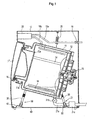
- the washing machine comprises a drum-shaped water tub 11 installed in a body 10 to receive wash water therein, and a rotating drum 12 rotatably installed in the water tub 11.
- the water tub 11 is obliquely installed in the body 10 such that a front surface portion of the water tub 11 having an entrance opening 11 a is positioned higher than a rear surface portion of the water tub 11.
- the rotating drum 12 is also obliquely installed in the water tub 11 by the same inclination as that of the water tub 11.
- a rotary shaft 13 is coupled to the center of a rear surface portion of the rotating drum 12 while being rotatably supported by the rear surface portion of the water tub 11.
- a motor 15 is mounted to the rear surface portion of the water tub 11 to rotate the rotating drum 12.
- the rotating drum 12 is perforated, throughout a peripheral portion thereof, with a plurality of holes 12b for the passage of wash water.
- a plurality of lifters 14 are provided at an inner peripheral surface of the rotating drum 12 and adapted to cause lifting and falling of laundry during rotation of the rotating drum 12.
- the body 10 is formed, at a front surface portion thereof, with an entrance opening 16 to put or take laundry into or out of the rotating drum 12.
- the entrance opening 16 is positioned to correspond to the entrance opening 11 a of the water tub 11 and an entrance opening 12a of the rotating drum 12.
- a door 17 is provided to open and close the entrance opening 16.
- the drainage device 21 includes a drain pipe 21 a, drain valve 21b and drain motor 21 c.
- the water tub 11 is supported by use of a plurality of dampers 30 supporting a lower portion of the water tub 11 and a plurality of shock-absorbing springs 25 supporting an upper portion of the water tub 11.
- a plurality of dampers 30 supporting a lower portion of the water tub 11 and a plurality of shock-absorbing springs 25 supporting an upper portion of the water tub 11.
- Each of the dampers 30, as shown in FIG. 2 has an upper end to be secured, by use of a fixing bolt (not shown), to an associated one of damperfixing members 31 arranged on an outer peripheral surface of the water tub 11. Also, a lower end of each damper 30, as shown in FIGS. 1 and 3 , is secured, by use of a fixing bolt 41, to an associated one of damper fixing units 50 arranged on a bottom plate 40 of the body 10.
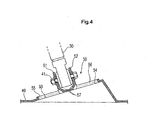
- Each damper fixing unit 50 on the bottom plate 40 of the body 10, as shown in FIGS. 3 and 4 has a first fixing piece 51 and a second fixing piece 52.
- the first and second fixing pieces 51 and 52 are cut from an obliquely raised supporting portion 42 of the bottom plate 40 and bent upward to support opposite sides of a lower end of the associated damper 30.
- the first and second fixing pieces 51 and 52 are perforated with holes 51a and 52a, respectively, to allow an associated one of the fixing bolts 41, which is used to secure the lower end of the damper 30 to the damper fixing unit 50, to penetrate and supported by the holes 51a and 52a.
- reinforcing portions 55 and 56 are provided along peripheries of cut portions 53 and 54 of the bottom plate 40 remaining after cutting the fixing and second fixing pieces 51 and 52 form the bottom plate 40.
- the reinforcing portions 55 and 56 as shown in FIG. 3 , are formed by bending peripheral portions around the cut portions 53 and 54 of the bottom plate 40 to protrude upward from an upper surface of the supporting portion 42
- the reinforcing portions 55 and 56 are integrally connected to lower end portions of the first and second fixing pieces 51 and 52.
- the reinforcing portions 55 and 56 are continuously formed along the peripheries of the cut portions 53 and 54 to have a larger height than the thickness of the bottom plate 40 while being connected to the first and second fixing pieces 51 and 52, respectively.
- the height of the reinforcing portions 53 and 54 may be substantially equal to the thickness of the bottom plate 40
- the reinforcing portions 55 and 56 are provided along a portion of the peripheries of the cut portions 53 and 54.
- Provision of the reinforcing portions 55 and 56 can reinforce rigidity of the bottom plate 40 around the cut portions 53 and 54. Accordingly, even if a relatively large load or shock is applied to the first and second fixing pieces 51 and 52 by the damper 30, there is little risk of damage to peripheral regions around the cut portions 53 and 54. Furthermore, by integrally connecting the reinforcing portions 55 and 56 to opposite sides of the respective lower end portions of the first and second fixing pieces 51 and 52 connected to the bottom plate 40, the rigidity of the first and second fixing pieces 51 and 52 can be significantly reinforced.
- the connecting portions between the first and second fixing pieces 51 and 52 and the bottom plate 40, more particularly the bent portions of the first and second fixing pieces 51 and 52, are centrally provided with reinforcing ribs 57 to achieve an increase in the rigidity of the connecting portions.
- the reinforcing ribs 57 in the present embodiment is shaped in the form of a pyramid however, various other shapes such as quarter of a sphere or half cylinder may be utilized. Accordingly, even after the lapse of long period of time, the drum type washing machine of the present invention has little risk of damage to connecting regions between the damper fixing units 50 and the bottom plate 40 or peripheral regions around the cut portions 53 and 54 of the bottom plate 40.
- the reinforcing portions 55 and56 and reinforcing ribs 57 can be simultaneously formed in the course of forming the damper fixing unit 50 to the bottom plate 40 by a conventional press machining process, and therefore, can be fabricated without an additional fabrication process therefor. This has the effect of significantly reinforcing the rigidity of peripheral regions around the damper fixing units 50.
- the present invention provides a drum type washing machine in which each cut portion of a bottom plate of a washing machine body remaining after forming a damper fixing unit is provided, along a periphery thereof with a reinforcing portion, thereby achieving an increase in a rigidity around the cut portion of the bottom plate as well as the damper fixing unit. Accordingly, even if a relatively large load or shock is applied to the damper fixing unit, it is possible to prevent damage to the damper fixing unit and a surrounding region thereof.
- the present invention may be applied to other types of washing machines, drying machines or machines having both the washing and drying capabilities as well as the disclosed drum type washing machine.
Landscapes
- Engineering & Computer Science (AREA)
- Textile Engineering (AREA)
- Main Body Construction Of Washing Machines And Laundry Dryers (AREA)
- Vibration Dampers (AREA)
Claims (20)
- Wasch-und/oder-Trocken-Maschine, die umfasst:ein Gehäuse (10);einen Behälter (11), der in dem Gehäuse installiert ist;wenigstens einen Dämpfer (30), der den Behälter (11) trägt; undeine Dämpfer-Fixiereinheit (50), die an einer Bodenplatte (40) des Gehäuses (10) angeordnet ist, um den Dämpfer an einer fixierten Position zu befestigen,dadurch gekennzeichnet, dass
die Dämpfer-Fixiereinheit (50) durch Schneiden der Bodenplatte (40) ausgebildet wird und durch einen verstärkenden Abschnitt (55), der um den geschnittenen Abschnitt (53, 54) der Bodenplatte (40) herum ausgebildet ist, verstärkte Steifigkeit aufweist. - Waschmaschine nach Anspruch 1, dadurch gekennzeichnet, dass der Behälter ein trommelförmiger Wasserbehälter (11) ist, der drehbar eine Drehtrommel abstützt, die in dem Wasserbehälter installiert ist.
- Wasch-und/oder-Trocken-Maschine nach Anspruch 1, wobei die Dämpfer-Fixiereinheit (50) ein erstes und ein zweites Fixierteil (51, 52) enthält.
- Wasch-und/oder-Trocken-Maschine nach Anspruch 3, wobei die Dämpfer-Fixiereinheiten (50) mit Löchern (51a, 52a) zum Aufnehmen eines Bolzens (41) versehen sind.
- Wasch-und/oder-Trocken-Maschine nach Anspruch 1, wobei der verstärkende Abschnitt (55, 56) ausgebildet wird, indem der Rand des geschnittenen Abschnitts (53, 54) der Bodenplatte nach oben gebogen wird.
- Wasch-und/oder-Trocken-Maschine nach Anspruch 5, wobei der verstärkende Abschnitt (55, 56) eine Höhe hat, die größer ist als die Dicke der Bodenplatte.
- Wasch-und/oder-Trocken-Maschine nach Anspruch 6, die des Weiteren verstärkende Rippen (57) umfasst, die in dem Verbindungsabschnitt des ersten und des zweiten Fixierteils (51, 52) ausgebildet sind.
- Wasch-und/oder-Trocken-Maschine nach Anspruch 7, wobei die verstärkenden Rippen (57) in Form einer Pyramide ausgebildet sind.
- Waschmaschine nach Anspruch 2, wobei der verstärkende Abschnitt (55, 56) ausgebildet wird, indem ein Randabschnitt (53, 54) so um den geschnittenen Abschnitt herum gebogen wird, dass er eine Höhe hat, die größer ist als eine Dicke der Bodenplatte, und er integral mit der Dämpfer-Fixiereinheit ausgebildet ist.
- Waschmaschine nach Anspruch 2, wobei der verstärkende Abschnitt von einem Rand des geschnittenen Abschnitts so gebogen wird, dass er von einer oberen Fläche der Bodenplatte (40) nach oben vorsteht, und er integral mit der Dämpfer-Fixiereinheit (50) ausgebildet ist.
- Waschmaschine nach Anspruch 9 , wobei die Dämpfer-Fixiereinheit (50) ein erstes sowie ein zweites Fixierteil (51, 52) umfasst, die aus der Bodenplatte (40) geschnitten und nach oben gebogen sind und gegenüberliegende Seiten eines unteren Endes den Dämpfer tragen, und jedes Fixierteil ein Loch (51a, 52a) aufweist, durch das sich ein Fixierbolzen (41) hindurch erstrecken kann.
- Waschmaschine nach Anspruch 10 , wobei die Dämpfer-Fixiereinheit (50) ein erstes sowie ein zweites Fixierteil (51, 52) umfasst, die aus der Bodenplatte (40) geschnitten und nach oben gebogen sind und gegenüberliegende Seiten eines unteren Endes den Dämpfer tragen, und jedes Fixierteil ein Loch (51a, 52a) aufweist, durch das sich ein Fixierbolzen (41) hindurch erstrecken kann.
- Waschmaschine nach Anspruch 11, wobei verstärkende Rippen (57) an Verbindungsabschnitten zwischen dem ersten und dem zweiten Fixierteil (51, 52) bzw. der Bodenplatte (40) ausgebildet sind.
- Waschmaschine nach Anspruch 12, wobei verstärkende Rippen (57) an Verbindungsabschnitten zwischen dem ersten und dem zweiten Fixierteil (51, 52) bzw. der Bodenplatte (40) ausgebildet sind.
- Waschmaschine nach Anspruch 2, wobei der verstärkende Abschnitt (55, 56) um den gesamten Rand des geschnitten Abschnitts herum ausgebildet ist.
- Waschmaschine nach Anspruch 2, wobei der verstärkende Abschnitt (55, 56) um einen Abschnitt des Randes des geschnittenen Abschnitts herum ausgebildet ist.
- Waschmaschine nach Anspruch 14, wobei die verstärkenden Rippen (57) die Form einer Pyramide haben.
- Waschmaschine nach Anspruch 2, wobei der verstärkende Abschnitt (55, 56) eine Höhe hat, die im Wesentlichen der Dicke der Bodenplatte gleich ist.
- Waschmaschine nach Anspruch 14, wobei die verstärkenden Rippen (57) die Form einer Viertelkugel haben.
- Waschmaschine nach Anspruch 14, wobei die verstärkenden Rippen (57) die Form eines Halbzylinders haben.
Applications Claiming Priority (1)
| Application Number | Priority Date | Filing Date | Title |
|---|---|---|---|
| KR1020050081292A KR100637668B1 (ko) | 2005-09-01 | 2005-09-01 | 세탁기 |
Publications (4)
| Publication Number | Publication Date |
|---|---|
| EP1760183A2 EP1760183A2 (de) | 2007-03-07 |
| EP1760183A3 EP1760183A3 (de) | 2008-05-14 |
| EP1760183B1 EP1760183B1 (de) | 2012-03-07 |
| EP1760183B2 true EP1760183B2 (de) | 2016-08-24 |
Family
ID=37499662
Family Applications (1)
| Application Number | Title | Priority Date | Filing Date |
|---|---|---|---|
| EP06119691.1A Active EP1760183B2 (de) | 2005-09-01 | 2006-08-29 | Waschmachine und/oder Trockner mit einem versteiften Dämpferlager |
Country Status (4)
| Country | Link |
|---|---|
| US (1) | US7739890B2 (de) |
| EP (1) | EP1760183B2 (de) |
| KR (1) | KR100637668B1 (de) |
| CN (1) | CN1924158B (de) |
Families Citing this family (9)
| Publication number | Priority date | Publication date | Assignee | Title |
|---|---|---|---|---|
| DE102006038960B3 (de) * | 2006-08-21 | 2007-10-18 | Miele & Cie. Kg | Kunststofflaugenbehälter für eine Waschmaschine mit Anbindung für Schwingungsdämpfer |
| WO2008053001A1 (en) * | 2006-10-31 | 2008-05-08 | Arcelik Anonim Sirketi | Washing machine vibration damper bracket with a cover against water ingress |
| KR100780754B1 (ko) | 2007-03-06 | 2007-11-30 | 삼성전자주식회사 | 세탁기 |
| US20110023554A1 (en) * | 2009-07-31 | 2011-02-03 | Bsh Home Appliances Corporation | Damping system for a household appliance |
| EP2848723B1 (de) | 2013-09-17 | 2021-02-24 | Electrolux Appliances Aktiebolag | Waschmaschine mit Dämpferelementen |
| KR102204005B1 (ko) | 2014-01-21 | 2021-01-18 | 엘지전자 주식회사 | 의류처리장치 및 그의 제조방법 |
| EP3115495B1 (de) | 2015-07-10 | 2018-08-08 | Vestel Beyaz Esya Sanayi Ve Ticaret A.S. | Wasch- und/oder trocknungsvorrichtung mit einem dämpfer |
| KR102712902B1 (ko) * | 2019-05-24 | 2024-10-07 | 삼성전자주식회사 | 세탁기 |
| EP4400642A1 (de) | 2023-01-12 | 2024-07-17 | BSH Hausgeräte GmbH | Waschmaschine mit verbesserter stossdämpferbefestigung und verfahren zu ihrer herstellung |
Family Cites Families (20)
| Publication number | Priority date | Publication date | Assignee | Title |
|---|---|---|---|---|
| US3039613A (en) * | 1959-04-30 | 1962-06-19 | Philco Corp | Laundry apparatus |
| US3103112A (en) * | 1961-10-04 | 1963-09-10 | Borg Warner | Fabric cleaning and drying machine |
| US3321940A (en) * | 1965-01-21 | 1967-05-30 | Gen Motors Corp | Rod suspension for clothes washing apparatus |
| US3516174A (en) * | 1968-02-26 | 1970-06-23 | Fedders Corp | Control arrangement for dry cleaning machines |
| DE3237759A1 (de) * | 1982-10-12 | 1984-04-12 | Fritz Bauer + Söhne oHG, 8503 Altdorf | Schwingungsfaehige abstuetzung fuer trommelwaschmaschinen |
| DE4105763A1 (de) | 1991-02-23 | 1992-08-27 | Suspa Compart Ag | Anlenkung eines schwingungsdaempfers fuer eine waschmaschine |
| JPH05253387A (ja) | 1992-03-12 | 1993-10-05 | Matsushita Electric Ind Co Ltd | ドラム式洗濯機 |
| US5548979A (en) * | 1995-01-23 | 1996-08-27 | General Electric Company | Horizontal axis clothes washing machine with tub suspension |
| US5946947A (en) * | 1996-05-21 | 1999-09-07 | Samsung Electronics Co., Ltd. | Clothes washing machine having vibration and noise damper |
| JP3164538B2 (ja) * | 1996-09-16 | 2001-05-08 | エルジー電子株式会社 | 洗濯機のダンパーアセンブリ用のスナッバ・ベース |
| JPH10216393A (ja) | 1997-02-12 | 1998-08-18 | Toshiba Corp | ドラム式洗濯機 |
| JPH1157281A (ja) | 1997-08-22 | 1999-03-02 | Toshiba Corp | 洗濯機 |
| JPH11114280A (ja) | 1997-10-16 | 1999-04-27 | Sanyo Electric Co Ltd | ドラム式洗濯機 |
| DE19921152A1 (de) * | 1999-05-07 | 2000-11-09 | Suspa Compart Ag | Anlenk-Vorrichtung zur Anlenkung eines Reibungsdämpfers an einem Maschinengestell einer Waschmaschine |
| KR100474913B1 (ko) * | 2002-08-09 | 2005-03-10 | 엘지전자 주식회사 | 드럼세탁기용 방진구조체 |
| US7204104B2 (en) * | 2003-01-30 | 2007-04-17 | Lg Electronics Inc. | Damper of drum type washing machine |
| KR100471456B1 (ko) * | 2003-03-26 | 2005-03-10 | 엘지전자 주식회사 | 드럼세탁기의 댐퍼 지지구조 |
| CN100503946C (zh) * | 2003-04-24 | 2009-06-24 | 乐金电子(天津)电器有限公司 | 滚筒洗衣机的减震器装配结构 |
| KR101054401B1 (ko) * | 2004-02-06 | 2011-08-04 | 엘지전자 주식회사 | 드럼세탁기의 댐퍼 조립구조 |
| KR101028079B1 (ko) * | 2004-03-02 | 2011-04-08 | 엘지전자 주식회사 | 세탁기의 댐퍼 조립구조 |
-
2005
- 2005-09-01 KR KR1020050081292A patent/KR100637668B1/ko not_active Expired - Fee Related
-
2006
- 2006-08-25 US US11/509,627 patent/US7739890B2/en active Active
- 2006-08-29 CN CN2006101261752A patent/CN1924158B/zh active Active
- 2006-08-29 EP EP06119691.1A patent/EP1760183B2/de active Active
Also Published As
| Publication number | Publication date |
|---|---|
| KR100637668B1 (ko) | 2006-10-24 |
| CN1924158A (zh) | 2007-03-07 |
| US7739890B2 (en) | 2010-06-22 |
| EP1760183B1 (de) | 2012-03-07 |
| US20070044518A1 (en) | 2007-03-01 |
| CN1924158B (zh) | 2010-08-18 |
| EP1760183A3 (de) | 2008-05-14 |
| EP1760183A2 (de) | 2007-03-07 |
Similar Documents
| Publication | Publication Date | Title |
|---|---|---|
| EP2000574B1 (de) | Rotierender Laugenbehälterkörper und Trommelwaschmaschine damit | |
| EP2108727B1 (de) | Trommelwaschmaschine und Lagergehäusestruktur davon | |
| US5862687A (en) | Drum washing machine | |
| KR102471463B1 (ko) | 세탁기 | |
| EP1760183B2 (de) | Waschmachine und/oder Trockner mit einem versteiften Dämpferlager | |
| KR101222861B1 (ko) | 샤프트플랜지 및 이를 갖는 세탁기 | |
| KR100445654B1 (ko) | 드럼 세탁기의 리프터 장착구조 | |
| EP1840256A1 (de) | Waschtrommel und Waschmaschine oder Trockner damit | |
| CN101994232A (zh) | 洗衣机及其外桶支撑结构 | |
| KR102712902B1 (ko) | 세탁기 | |
| US8516861B2 (en) | Washing machine | |
| TWI421388B (zh) | Drum washing machine | |
| KR101638903B1 (ko) | 세탁장치 | |
| KR101217118B1 (ko) | 세탁기 | |
| US11668123B2 (en) | Washing machine | |
| JP2006204497A (ja) | 洗濯機 | |
| JP2007020992A (ja) | ドラム式洗濯機 | |
| KR102838601B1 (ko) | 세탁기의 운송용 볼트 체결부 | |
| KR100767689B1 (ko) | 의류처리장치 | |
| US20160069011A1 (en) | Top-loading type washing machine | |
| KR101362369B1 (ko) | 밸런서를 구비한 세탁기 | |
| KR101139251B1 (ko) | 드럼세탁기 |
Legal Events
| Date | Code | Title | Description |
|---|---|---|---|
| PUAI | Public reference made under article 153(3) epc to a published international application that has entered the european phase |
Free format text: ORIGINAL CODE: 0009012 |
|
| AK | Designated contracting states |
Kind code of ref document: A2 Designated state(s): AT BE BG CH CY CZ DE DK EE ES FI FR GB GR HU IE IS IT LI LT LU LV MC NL PL PT RO SE SI SK TR |
|
| AX | Request for extension of the european patent |
Extension state: AL BA HR MK YU |
|
| PUAL | Search report despatched |
Free format text: ORIGINAL CODE: 0009013 |
|
| AK | Designated contracting states |
Kind code of ref document: A3 Designated state(s): AT BE BG CH CY CZ DE DK EE ES FI FR GB GR HU IE IS IT LI LT LU LV MC NL PL PT RO SE SI SK TR |
|
| AX | Request for extension of the european patent |
Extension state: AL BA HR MK RS |
|
| 17P | Request for examination filed |
Effective date: 20080620 |
|
| 17Q | First examination report despatched |
Effective date: 20081205 |
|
| AKX | Designation fees paid |
Designated state(s): DE FR GB |
|
| GRAP | Despatch of communication of intention to grant a patent |
Free format text: ORIGINAL CODE: EPIDOSNIGR1 |
|
| RIN1 | Information on inventor provided before grant (corrected) |
Inventor name: YANG, YOON SEOK Inventor name: LEE, HONG YEOL Inventor name: ROH, HYOUNG HOON |
|
| GRAS | Grant fee paid |
Free format text: ORIGINAL CODE: EPIDOSNIGR3 |
|
| GRAA | (expected) grant |
Free format text: ORIGINAL CODE: 0009210 |
|
| AK | Designated contracting states |
Kind code of ref document: B1 Designated state(s): DE FR GB |
|
| REG | Reference to a national code |
Ref country code: GB Ref legal event code: FG4D |
|
| REG | Reference to a national code |
Ref country code: DE Ref legal event code: R096 Ref document number: 602006028004 Country of ref document: DE Effective date: 20120503 |
|
| RAP2 | Party data changed (patent owner data changed or rights of a patent transferred) |
Owner name: SAMSUNG ELECTRONICS CO., LTD. |
|
| PLBI | Opposition filed |
Free format text: ORIGINAL CODE: 0009260 |
|
| 26 | Opposition filed |
Opponent name: ELECTROLUX HOME PRODUCTS CORPORATION N.V. Effective date: 20121207 |
|
| PLAX | Notice of opposition and request to file observation + time limit sent |
Free format text: ORIGINAL CODE: EPIDOSNOBS2 |
|
| REG | Reference to a national code |
Ref country code: DE Ref legal event code: R026 Ref document number: 602006028004 Country of ref document: DE Effective date: 20121207 |
|
| PLAF | Information modified related to communication of a notice of opposition and request to file observations + time limit |
Free format text: ORIGINAL CODE: EPIDOSCOBS2 |
|
| PLBB | Reply of patent proprietor to notice(s) of opposition received |
Free format text: ORIGINAL CODE: EPIDOSNOBS3 |
|
| PLAY | Examination report in opposition despatched + time limit |
Free format text: ORIGINAL CODE: EPIDOSNORE2 |
|
| PLAH | Information related to despatch of examination report in opposition + time limit modified |
Free format text: ORIGINAL CODE: EPIDOSCORE2 |
|
| PLBC | Reply to examination report in opposition received |
Free format text: ORIGINAL CODE: EPIDOSNORE3 |
|
| PLBP | Opposition withdrawn |
Free format text: ORIGINAL CODE: 0009264 |
|
| PUAH | Patent maintained in amended form |
Free format text: ORIGINAL CODE: 0009272 |
|
| STAA | Information on the status of an ep patent application or granted ep patent |
Free format text: STATUS: PATENT MAINTAINED AS AMENDED |
|
| REG | Reference to a national code |
Ref country code: FR Ref legal event code: PLFP Year of fee payment: 11 |
|
| 27A | Patent maintained in amended form |
Effective date: 20160824 |
|
| AK | Designated contracting states |
Kind code of ref document: B2 Designated state(s): DE FR GB |
|
| REG | Reference to a national code |
Ref country code: DE Ref legal event code: R102 Ref document number: 602006028004 Country of ref document: DE |
|
| REG | Reference to a national code |
Ref country code: FR Ref legal event code: PLFP Year of fee payment: 12 |
|
| REG | Reference to a national code |
Ref country code: FR Ref legal event code: PLFP Year of fee payment: 13 |
|
| PGFP | Annual fee paid to national office [announced via postgrant information from national office to epo] |
Ref country code: DE Payment date: 20250721 Year of fee payment: 20 |
|
| PGFP | Annual fee paid to national office [announced via postgrant information from national office to epo] |
Ref country code: GB Payment date: 20250722 Year of fee payment: 20 |
|
| PGFP | Annual fee paid to national office [announced via postgrant information from national office to epo] |
Ref country code: FR Payment date: 20250725 Year of fee payment: 20 |