EP1759975A2 - Lenkungsdämpfer - Google Patents
Lenkungsdämpfer Download PDFInfo
- Publication number
- EP1759975A2 EP1759975A2 EP06005404A EP06005404A EP1759975A2 EP 1759975 A2 EP1759975 A2 EP 1759975A2 EP 06005404 A EP06005404 A EP 06005404A EP 06005404 A EP06005404 A EP 06005404A EP 1759975 A2 EP1759975 A2 EP 1759975A2
- Authority
- EP
- European Patent Office
- Prior art keywords
- case
- rotating
- damper
- rotating body
- rotating shaft
- Prior art date
- Legal status (The legal status is an assumption and is not a legal conclusion. Google has not performed a legal analysis and makes no representation as to the accuracy of the status listed.)
- Withdrawn
Links
Images










Classifications
-
- B—PERFORMING OPERATIONS; TRANSPORTING
- B62—LAND VEHICLES FOR TRAVELLING OTHERWISE THAN ON RAILS
- B62K—CYCLES; CYCLE FRAMES; CYCLE STEERING DEVICES; RIDER-OPERATED TERMINAL CONTROLS SPECIALLY ADAPTED FOR CYCLES; CYCLE AXLE SUSPENSIONS; CYCLE SIDECARS, FORECARS, OR THE LIKE
- B62K21/00—Steering devices
- B62K21/08—Steering dampers
-
- F—MECHANICAL ENGINEERING; LIGHTING; HEATING; WEAPONS; BLASTING
- F16—ENGINEERING ELEMENTS AND UNITS; GENERAL MEASURES FOR PRODUCING AND MAINTAINING EFFECTIVE FUNCTIONING OF MACHINES OR INSTALLATIONS; THERMAL INSULATION IN GENERAL
- F16F—SPRINGS; SHOCK-ABSORBERS; MEANS FOR DAMPING VIBRATION
- F16F9/00—Springs, vibration-dampers, shock-absorbers, or similarly-constructed movement-dampers using a fluid or the equivalent as damping medium
- F16F9/10—Springs, vibration-dampers, shock-absorbers, or similarly-constructed movement-dampers using a fluid or the equivalent as damping medium using liquid only; using a fluid of which the nature is immaterial
- F16F9/12—Devices with one or more rotary vanes turning in the fluid any throttling effect being immaterial, i.e. damping by viscous shear effect only
Definitions
- the present invention relates to a steering damper apparatus which is preferably applied to a saddle riding type vehicle such as a motorcycle or the like.
- a rotating shaft of a damper is directly coupled to a steering shaft, and the damper is directly rotated on the basis of a rotation of a handle.
- the damper is directly rotated on the basis of the rotation of the handle, and a rotation angle of the handle is identical with a rotation angle of the damper. Accordingly, in the motorcycle or the like, when rotating the damper at a small rotation angle such as about 30 degree of the handle, it is hard to obtain a high damping force by a downsized damper.
- An object of the present invention is to improve a freedom of a layout of a damper as well as intending to downsize the damper, in a steering damper apparatus.
- the present invention relates to a steering damper apparatus comprising: a steering shaft pivoted to a head pipe arranged in a front portion of a vehicle body frame; a rotary type viscous fluid damper arranged in a rear side of the head pipe of the vehicle body frame; and a linkage wound around a drive wheel provided in the steering shaft and a driven wheel provided in a rotating shaft of the viscous fluid damper. Further a diameter of the drive wheel is larger than a diameter of the driven wheel.
- FIG. 1 shows a part of a motorcycle.
- a steering shaft 2 is pivoted to a head pipe (not shown) arranged in a front portion of a vehicle body frame 1, and handles 4 are attached to right and left sides of an upper bracket 3 integrally formed with the steering shaft 2.
- a steering damper apparatus 10 is structured such as to generate a damping force against an unexpected turning for preventing the handles 4 from being unexpectedly turned by a disturbance such a kickback or the like, and is constructed by fixedly arranging a rotary type electroviscous fluid damper 20 in a rear side of the head pipe in the vehicle frame 1 by a mounting bolt 21.
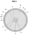
- the electroviscous fluid damper 20 is structured, as shown in FIGS. 2 and 3, such that an electroviscous fluid is sealed in a case 30, a rotating body 40 is installed in the case 30, a first electrode (+) 40A is provided in the rotating body 40, and a second electrode (-) 30A is provided in the case 30 so as to face the first electrode 40A. Further, a torque (a damping force) of the rotating body 40 can be controlled by filling a facing gap between both the first and second electrodes 40A and 30A with the electroviscous fluid, and applying an electric field between both the first and second electrodes 40A and 30A.
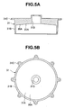
- the case 30 is constituted by upper and lower case bodies 31 and 32 as shown in FIGS. 4 to 6B, and is structured by fitting an outer surface of a side wall 31B coming down from an outer periphery of a top surface 31A of the upper case body 31 to an inner surface of a side wall 32B coming up from an outer periphery of a bottom surface 32A of the lower case body 32 via a seal member 33.
- the second electrode 30A is formed by applying a coating of a metallic paint or the like on inner surfaces of the top surface 31A and the side wall 31B of the upper case body 31, and in the case that the lower case body 32 is formed by resin, the second electrode 30A is formed by applying a coating of the metallic paint or the like on the bottom surface 32A of the lower case body 32.
- the seal member 33 is constituted by an O-ring, and is loaded to an annular groove provided close to a lower portion of an outer surface of the side wall 31B of the upper case body 31.
- the upper and lower case bodies 31 and 32 are integrally formed by screwing a locking screw 34A inserted and attached to an outer peripheral mounting piece 31C of the upper case body 31 to a thread hole 34B of an outer peripheral mounting piece 32C of the lower case body 32.
- the rotating body 40 is structured, as shown in FIGS. 4 and 7A to 7C, such that a thick plate-like rotating plate 42 is provided in the rotating shaft 41 pivoted to the case 30 in a liquid tight manner.
- the first electrode 40A is formed by applying a coating of a metallic paint or the like to a surface of the rotating plate 42.
- the rotating shaft 41 is constituted by an upper shaft 41A protruding to an upper side of the rotating plate 42, and a lower shaft 41B protruding to a lower side.
- the upper case body 31 is provided with a penetrating bearing hole 31D in a center portion of the top surface 31A, and a resin insulating bush 35 is press-fitteed to the bearing hole 31D.
- the insulating bush 35 constituted by a penetrating tube body, is press-fitted to the bearing hole 31D.
- the insulating bush 35 has a seal member 35A such as an O-ring in an outer peripheral annular groove, a seal member 35B such as an O-ring seated in an inner peripheral annular groove, and a bearing bush 36 having a Teflon (trade mark) coated metal ring in an inner peripheral step hole.
- the lower case body 32 is provided with an occlusive bearing hole 32D in a center portion of the bottom surface 32A.
- a resin insulating bush 37 is pressure inserted to the bearing hole 32D.
- the insulating bush 37 is constituted by a closed-end tube body, and is provided with a bearing bush 38 having a Teflon (trade mark) coated metal ring in an inner peripheral hole.
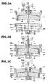
- the electroviscous fluid damper 20 is assembled by inserting the rotating shaft 41 (the upper shaft 41A) of the rotating body 40 to the seal member 35B provided in the insulating bush 35 of the upper case body 31, and the bearing bush 36, forming a unit assembly in which a center side of an upper surface of the rotating plate 42 is brought into contact with a lower end surface of the insulating bush 35, inserting the upper case body 31 and the rotating body 40 constituting the unit assembly to the lower case body 32 loaded with the electroviscous fluid, inserting the rotating shaft 41 (the lower shaft 41B) of the rotating body 40 to the bearing bush 38 provided in the insulating bush 37 of the lower case body 32, bringing a center side of a lower surface of the rotating plate 42 into contact with an upper end surface of the insulating bush 37, lapping the outer peripheral mounting piece 31C of the upper case body 31 over the outer peripheral mounting piece 32C of the lower case body 32 and fastening them by a locking screw 34A.
- the rotating shaft 41 the upper shaft 41A
- the steering damper apparatus 10 is structured, as shown in FIG. 1, such that a drive wheel 11 constituted by a gear is fixed to an upper end portion of the steering shaft 2 by a nut 11A, a driven wheel 12 constituted by a gear is formed in an outer periphery of the rotating shaft 41 (the upper shaft 41A) protruding to an outer side from the case 30 (the bearing hole 31D of the upper case body 31) of the electroviscous fluid damper 20 arranged in a rear side of the head pipe in the vehicle body frame 1, and a linkage 13 constituted by a belt (or a chain) is wound around the drive wheel 11 and the driven wheel 12. At this time, a diameter of the drive wheel 11 is formed larger than a diameter of the driven wheel 12.
- the steering damper apparatus 10 if the rotation of the steering shaft 2 rotated by the handle 4 is amplified on the basis of a diameter ratio of the drive wheel 11 with respect to the driven wheel 12, and then, is transmitted to the electroviscous fluid damper 20, the rotating body 40 rotates while shearing the electroviscous fluid between the rotating body 40 and the case 30.
- the electroviscous fluid damper 20 when the electric field is not applied between the first and second electrodes 40A and 30A, the torque of the rotating body 40 is small and the damping force is low because the electroviscous fluid damper within the case 30 has a low viscosity.
- the viscosity of the electroviscous fluid is made high by applying the electric field between the first and second electrodes 40A and 30A, the torque of the rotating body 40 becomes large and the damping force becomes high. It is possible to control the viscosity of the electroviscous fluid so as to control the damping force on the basis of rise and fall of a voltage applied between the first and second electrodes 40A and 30A.
- the electroviscous fluid damper 20 is structured such that each of an upper surface 42A and a lower surface 42B of the rotating plate 42 of the rotating body 40 is inclined downward toward an outer periphery from a center side, and each of the top surface 31A and the bottom surface 32A of the case 30 (the upper and lower case bodies 31 and 32) facing each of the upper surface 42A and the lower surface 42B of the rotating plate 42 via upper and lower gaps is inclined downward toward an outer periphery from a center side.
- the electroviscous fluid damper 20 is provided with a liquid discharge hole 51 in an axial direction of a center portion of the rotating shaft 41 of the rotating body 40, is provided with a communication hole 52 intersecting in a diametrical direction or a radial direction from the liquid discharge hole 51 and formed slightly downward toward a gap on the upper surface 42A of the rotating plate 42 in the upper shaft 41A side, and is provided with a communication hole 53 intersecting in the diametrical direction or the radial direction from the liquid discharge hole 51 and formed downward toward a gap below the lower surface 42B of the rotating plate 42 in the lower shaft 41B side.
- a communication groove 52A penetrating in the diametrical direction or the radial direction is formed in a lower end surface of the insulating bush 35 to which the upper shaft 41A is inserted and which is brought into contact with the center side of the upper surface of the rotating plate 42 as mentioned above, whereby the communication hole 52 of the rotating shaft 41 can be communicated with the gap on the upper surface 42A of the rotating plate 42.
- a communication groove 53A penetrating in the diametrical direction or the radial direction is formed in an upper end surface of the insulating bush 37 to which the lower shaft 41B is inserted and which is brought into contact with the center side of the lower surface of the rotating plate 42 as mentioned above, whereby the communication hole 53 of the rotating shaft 41 can be communicated with the gap below the lower surface 42B of the rotating plate 42.
- the electroviscous fluid damper 20 passes through the liquid discharge hole 51 provided in the rotating shaft 41 from the lower end surface of the rotating shaft 41 to the upper end surface.
- the electroviscous fluid damper 20 is structured such that the rotating shaft 41 protrudes to an outer side from the bearing hole 31D of the upper case body 31, and the drain bolt 51A is detachably screwed to an external opening end of the liquid discharge hole 51 provided in the rotating shaft 41 via the packing 51B.
- an assembling procedure of the electroviscous fluid damper 20 and a discharging procedure of the bubbles within the case 30 are as follows (FIG. 8A to 8C).
- An embodiment 2 is different from the embodiment 1 in structures of the case 30 (the lower case body 32) of the electroviscous fluid damper 20 and the rotating body 40 (the rotating plate 42).
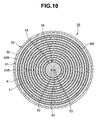
- the electroviscous fluid damper 20 is structured, as shown in FIGS. 9 and 10, such that the rotating plate 42 of the rotating body 40 is formed thick only in a center side and thin in an outer peripheral side, a thick plate side upper surface 42A and a thin plate side upper surface 42A are continuously formed, and a thick plate side lower surface 42B and a thin plate side lower surface 42B are formed in a step shape.
- an annular protrusion K in the present embodiment is provided in the rotating plate 42 of the rotating body 40, the thin plate side lower surface 42B in the present embodiment (FIGS.
- an annular protrusion L in the present embodiment is provided in the case 30, the bottom surface 32A of the lower case body 32 in the present embodiment (FIGS. 13A and 13B).
- the annular protrusion K of the rotating body 40 and the annular protrusion L of the case 30 are fitted in such a manner that they can relatively rotate with each other via a gap
- the first electrode 40A is formed in a surface including the annular protrusion K of the rotating body 40
- the second electrode 30A is formed in an inner surface (the inner surfaces of the top surface 31A and the side wall 31B of the upper case body 31, and the bottom surface 32A of the lower case body 32) including the annular protrusion L of the case 30.
- the electroviscous fluid damper 20 is structured, as shown in FIGS. 14A to 14C, such that the annular protrusion K of the rotating body 40 is provided at each of a plurality of coaxial rotational radial positions on the lower surface 42B of the rotating plate 42. Further, the annular protrusion L of the case 30 is provided at each of a plurality of coaxial rotational radial positions on the bottom surface 32A of the lower case body 32, as shown in FIGS. 13A and 13B.
- the electroviscous fluid damper 20 is provided with a through hole 54 extending along a radial direction of the lower surface 42B of the rotating plate 42, in a root of the annular protrusion K provided in the lower surface 42B of the rotating plate 42, on a diameter extending in a diametrical direction or a radial direction of the rotating plate 42 intersecting the rotating shaft 41 of the rotating body 40, in addition to the structure in the embodiment 1, as shown in FIGS. 9, 10 and 14A to 14C.
- a communication hole 55 formed downward is provided in such a manner as to intersect in the diametrical direction or the radial direction from the liquid discharge hole 51 of the rotating shaft 41 and extend along the lower surface 42B of the rotating plate 42.
- An embodiment 3 is different from the embodiment 1 in structures of the case 30 (the upper and lower case bodies 31 and 32) of the electroviscous fluid damper 20 and the rotating body 40 (the rotating plate 42).
- the electroviscous fluid damper 20 is structured, as shown in FIGS. 15, such that the rotating plate 42 of the rotating body 40 is formed thick only in a center side and thin in an outer peripheral side, a thin plate side upper surface 42A is formed in a step shape such as to be in a lower position with respect to a thick plate side upper surface 42A, and a thin plate side lower surface 42B is formed in a step shape such as to be in an upper position with respect to a thick plate side lower surface 42B.
- the upward annular protrusion K1 of the rotating body 40 and the downward annular protrusion L1 of the case 30, and the downward annular protrusion K2 of the rotating body 40 and the upward annular protrusion L2 of the case 30 are respectively fitted via the gaps so as to be relatively rotatable, the first electrode 40A is formed in a surface including the protrusions K1 and K2 of the rotating body 40, and the second electrode 30A is formed in an inner surface (the inner surfaces of the top surface 31A and the side wall 31B of the upper case body 31, and the side surface 32A of the lower case body 32) including the protrusions L1 and L2 of the case 30.
- the electroviscous fluid damper 20 is structured such that each of the protrusions K1 and K2 of the rotating body 40 is provided at each of a plurality of coaxial rotational radial positions on the upper surface 42A and the lower surface 42B of the rotating plate 42. Further, each of the protrusions L1 and L2 of the case 30 is provided at each of a plurality of coaxial rotational radial positions on the top surface 31A of the upper case body 31 and the bottom surface 32A of the lower case body 32.
- the electroviscous fluid damper 20 is provided with a through hole 54 extending along a radial direction of the lower surface 42B of the rotating plate 42, in a root of the downward annular protrusion K2 provided in the lower surface 42B of the rotating plate 42, on a diameter extending in a diametrical direction or a radial direction of the rotating plate 42 intersecting the rotating shaft 41 of the rotating body 40, in addition to the structure in the embodiment 1.
- a communication hole 55 formed downward is provided in such a manner as to intersect in the diametrical direction or the radial direction from the liquid discharge hole 51 of the rotating shaft 41 and extend along the lower surface 42B of the rotating plate 42.
- the electroviscous fluid damper 20 is provided with a through hole 56 extending along a radial direction of the top surface 31A of the upper case body 31, in a root of the downward annular protrusion L1 provided in the top surface 31A, on a diameter extending in a diametrical direction or a radial direction of the upper case body 31, in addition to the structure in the embodiment 1.
- a communication hole 57 formed downward is provided along the top surface 31A of the upper case body 31 from the liquid discharge hole 51 of the rotating shaft 41.
- the communication hole 57 is in common with the communication hole 52 in the embodiment 1.
- the steering damper apparatus in accordance with the present invention can be applied to a structure using a viscous fluid damper in which a root of a single vane is provided in an oscillating shaft (for example, Japanese Patent Application Laid-open No. 2003-104269 ), without the limitation of the viscous fluid damper having the rotating plate provided in an entire periphery around the rotating shaft.
- the viscous fluid damper in accordance with the present invention can be applied to a structure using a viscous fluid such as silicone oil or the like, without being limited to the electroviscous fluid damper.
Landscapes
- Engineering & Computer Science (AREA)
- General Engineering & Computer Science (AREA)
- Mechanical Engineering (AREA)
- Fluid-Damping Devices (AREA)
Applications Claiming Priority (1)
| Application Number | Priority Date | Filing Date | Title |
|---|---|---|---|
| JP2005250256A JP2007062524A (ja) | 2005-08-30 | 2005-08-30 | ステアリングダンパ装置 |
Publications (2)
| Publication Number | Publication Date |
|---|---|
| EP1759975A2 true EP1759975A2 (de) | 2007-03-07 |
| EP1759975A3 EP1759975A3 (de) | 2008-05-07 |
Family
ID=37459310
Family Applications (1)
| Application Number | Title | Priority Date | Filing Date |
|---|---|---|---|
| EP06005404A Withdrawn EP1759975A3 (de) | 2005-08-30 | 2006-03-16 | Lenkungsdämpfer |
Country Status (3)
| Country | Link |
|---|---|
| US (1) | US20070045982A1 (de) |
| EP (1) | EP1759975A3 (de) |
| JP (1) | JP2007062524A (de) |
Cited By (2)
| Publication number | Priority date | Publication date | Assignee | Title |
|---|---|---|---|---|
| WO2016042526A1 (en) * | 2014-09-19 | 2016-03-24 | Tottolomondo Domenico | Fluid-dynamic device and fluid-dynamic assembly comprising such device |
| CN110546060A (zh) * | 2017-05-08 | 2019-12-06 | 宝马股份公司 | 用于机动车的转向组件和机动车 |
Families Citing this family (8)
| Publication number | Priority date | Publication date | Assignee | Title |
|---|---|---|---|---|
| JP4825623B2 (ja) * | 2006-08-30 | 2011-11-30 | 本田技研工業株式会社 | 車両のステアリングダンパ取付構造 |
| US7793957B2 (en) * | 2007-06-29 | 2010-09-14 | Kayaba Industry Co., Ltd. | Steering damping device |
| US8459137B1 (en) | 2010-04-07 | 2013-06-11 | Hydro-Gear Limited Partnership | Control assembly for drive system |
| EP3688328A4 (de) | 2017-09-28 | 2021-06-30 | Saint-Gobain Performance Plastics Corporation | Anordnung für ein lager und verfahren zur herstellung und verwendung davon |
| US10946925B2 (en) * | 2017-12-14 | 2021-03-16 | George John Athanasiou | Multi positional rotary steering damper assembly |
| US11454292B2 (en) * | 2020-08-14 | 2022-09-27 | DRiV Automotive Inc. | Damper assembly |
| GB2632621A (en) * | 2023-02-14 | 2025-02-19 | Zf Automotive Uk Ltd | Steering assembly for a vehicle |
| TWI847632B (zh) * | 2023-03-27 | 2024-07-01 | 天心工業股份有限公司 | 適用於自行車的車頭碗組 |
Citations (1)
| Publication number | Priority date | Publication date | Assignee | Title |
|---|---|---|---|---|
| JP2003104269A (ja) | 2001-10-01 | 2003-04-09 | Honda Motor Co Ltd | 鞍乗り型車両用ステアリングダンパ装置 |
Family Cites Families (4)
| Publication number | Priority date | Publication date | Assignee | Title |
|---|---|---|---|---|
| JPH10159885A (ja) * | 1996-11-22 | 1998-06-16 | Nifco Inc | 電気粘性流体ダンパー |
| JP4640905B2 (ja) * | 2001-04-06 | 2011-03-02 | 本田技研工業株式会社 | ステアリングダンパ装置 |
| JP4571338B2 (ja) * | 2001-05-25 | 2010-10-27 | 本田技研工業株式会社 | 車両用ステアリングダンパー装置 |
| US7021433B2 (en) * | 2003-03-20 | 2006-04-04 | Honda Motor Co., Ltd. | Vehicle steering damper, steering damper kit for motorcycle, and motorcycle incorporating same |
-
2005
- 2005-08-30 JP JP2005250256A patent/JP2007062524A/ja not_active Withdrawn
-
2006
- 2006-03-14 US US11/375,301 patent/US20070045982A1/en not_active Abandoned
- 2006-03-16 EP EP06005404A patent/EP1759975A3/de not_active Withdrawn
Patent Citations (1)
| Publication number | Priority date | Publication date | Assignee | Title |
|---|---|---|---|---|
| JP2003104269A (ja) | 2001-10-01 | 2003-04-09 | Honda Motor Co Ltd | 鞍乗り型車両用ステアリングダンパ装置 |
Cited By (3)
| Publication number | Priority date | Publication date | Assignee | Title |
|---|---|---|---|---|
| WO2016042526A1 (en) * | 2014-09-19 | 2016-03-24 | Tottolomondo Domenico | Fluid-dynamic device and fluid-dynamic assembly comprising such device |
| CN110546060A (zh) * | 2017-05-08 | 2019-12-06 | 宝马股份公司 | 用于机动车的转向组件和机动车 |
| CN110546060B (zh) * | 2017-05-08 | 2022-04-05 | 宝马股份公司 | 用于机动车的转向组件和机动车 |
Also Published As
| Publication number | Publication date |
|---|---|
| EP1759975A3 (de) | 2008-05-07 |
| JP2007062524A (ja) | 2007-03-15 |
| US20070045982A1 (en) | 2007-03-01 |
Similar Documents
| Publication | Publication Date | Title |
|---|---|---|
| EP1759975A2 (de) | Lenkungsdämpfer | |
| CA2155507A1 (en) | Stress dissipation gear and method of making same | |
| US11618495B2 (en) | Steering device | |
| EP2489901A1 (de) | Schneckenuntersetzungsgetriebe | |
| US5694810A (en) | Rack and pinion steering device | |
| US20070176392A1 (en) | Motorcycle provided with a steering damper | |
| EP3475148A1 (de) | Kugelgewindetrieb einer elektromechanischen servolenkung mit integriertem schrägkugellager und kompensation unterschiedlicher wärmeausdehnungen | |
| RU142143U1 (ru) | Электрический усилитель рулевого управления для транспортных средств | |
| CN1699107A (zh) | 动力转向装置 | |
| US20100124455A1 (en) | Revolute joint with integrated radial compliance | |
| US7914023B2 (en) | Parallelogram-style steering mechanism having a relay rod bushing | |
| US20200094646A1 (en) | Vehicle height adjusting apparatus | |
| JP2007064329A (ja) | 電気粘性流体ダンパ | |
| JP2007064330A (ja) | 粘性流体ダンパ | |
| US12445008B2 (en) | Hub motor | |
| JP4285227B2 (ja) | エンジンカバーの取付構造 | |
| JP2007064331A (ja) | 電気粘性流体ダンパ | |
| CN118529125A (zh) | 用于车辆的转向组件 | |
| CN104315070A (zh) | 一种可调阻尼器装置 | |
| EP3782896B1 (de) | Vibrationsentkopplung einer tretlagereinheit für ein elektrofahrrad | |
| US20090139597A1 (en) | Tubular valve tower extension element | |
| EP2789525B1 (de) | Lenkvorrichtung | |
| US20050180859A1 (en) | Four-in pump | |
| CN107264614A (zh) | 矿用自卸车转向柱上花键轴和花键套的轴向固定结构 | |
| KR0127521Y1 (ko) | 파워스티어링의 스트로크 조정장치 |
Legal Events
| Date | Code | Title | Description |
|---|---|---|---|
| PUAI | Public reference made under article 153(3) epc to a published international application that has entered the european phase |
Free format text: ORIGINAL CODE: 0009012 |
|
| AK | Designated contracting states |
Kind code of ref document: A2 Designated state(s): AT BE BG CH CY CZ DE DK EE ES FI FR GB GR HU IE IS IT LI LT LU LV MC NL PL PT RO SE SI SK TR |
|
| AX | Request for extension of the european patent |
Extension state: AL BA HR MK YU |
|
| PUAL | Search report despatched |
Free format text: ORIGINAL CODE: 0009013 |
|
| AK | Designated contracting states |
Kind code of ref document: A3 Designated state(s): AT BE BG CH CY CZ DE DK EE ES FI FR GB GR HU IE IS IT LI LT LU LV MC NL PL PT RO SE SI SK TR |
|
| AX | Request for extension of the european patent |
Extension state: AL BA HR MK YU |
|
| AKX | Designation fees paid | ||
| STAA | Information on the status of an ep patent application or granted ep patent |
Free format text: STATUS: THE APPLICATION IS DEEMED TO BE WITHDRAWN |
|
| 18D | Application deemed to be withdrawn |
Effective date: 20081108 |
|
| REG | Reference to a national code |
Ref country code: DE Ref legal event code: 8566 |