EP1759631B1 - Fluorezentlicht Bilddarstellungsverfahren und Gerät dafür - Google Patents
Fluorezentlicht Bilddarstellungsverfahren und Gerät dafür Download PDFInfo
- Publication number
- EP1759631B1 EP1759631B1 EP06019795A EP06019795A EP1759631B1 EP 1759631 B1 EP1759631 B1 EP 1759631B1 EP 06019795 A EP06019795 A EP 06019795A EP 06019795 A EP06019795 A EP 06019795A EP 1759631 B1 EP1759631 B1 EP 1759631B1
- Authority
- EP
- European Patent Office
- Prior art keywords
- image
- light
- fluorescent
- tissue
- light image
- Prior art date
- Legal status (The legal status is an assumption and is not a legal conclusion. Google has not performed a legal analysis and makes no representation as to the accuracy of the status listed.)
- Expired - Lifetime
Links
- 238000000034 method Methods 0.000 title claims description 29
- 238000003780 insertion Methods 0.000 claims description 33
- 230000037431 insertion Effects 0.000 claims description 33
- 239000004065 semiconductor Substances 0.000 claims description 14
- 230000003287 optical effect Effects 0.000 description 36
- 230000006870 function Effects 0.000 description 35
- 239000003086 colorant Substances 0.000 description 18
- 239000000835 fiber Substances 0.000 description 18
- 230000000875 corresponding effect Effects 0.000 description 17
- 230000000007 visual effect Effects 0.000 description 11
- 238000001228 spectrum Methods 0.000 description 8
- 239000002131 composite material Substances 0.000 description 7
- 239000003365 glass fiber Substances 0.000 description 6
- 230000008569 process Effects 0.000 description 6
- 238000003745 diagnosis Methods 0.000 description 5
- 201000010099 disease Diseases 0.000 description 5
- 208000037265 diseases, disorders, signs and symptoms Diseases 0.000 description 5
- 208000003322 Coinfection Diseases 0.000 description 4
- XUIMIQQOPSSXEZ-UHFFFAOYSA-N Silicon Chemical compound [Si] XUIMIQQOPSSXEZ-UHFFFAOYSA-N 0.000 description 4
- 230000008859 change Effects 0.000 description 4
- 238000006243 chemical reaction Methods 0.000 description 4
- 230000001276 controlling effect Effects 0.000 description 4
- 208000015181 infectious disease Diseases 0.000 description 4
- 229910052710 silicon Inorganic materials 0.000 description 4
- 239000010703 silicon Substances 0.000 description 4
- 230000004913 activation Effects 0.000 description 3
- 241001085205 Prenanthella exigua Species 0.000 description 2
- 230000002596 correlated effect Effects 0.000 description 2
- 230000001419 dependent effect Effects 0.000 description 2
- 230000000694 effects Effects 0.000 description 2
- 230000009467 reduction Effects 0.000 description 2
- 230000035945 sensitivity Effects 0.000 description 2
- 230000001953 sensory effect Effects 0.000 description 2
- 238000010586 diagram Methods 0.000 description 1
- 230000005684 electric field Effects 0.000 description 1
- 238000005516 engineering process Methods 0.000 description 1
- 238000001914 filtration Methods 0.000 description 1
- 238000005286 illumination Methods 0.000 description 1
- 230000008595 infiltration Effects 0.000 description 1
- 238000001764 infiltration Methods 0.000 description 1
- 230000001678 irradiating effect Effects 0.000 description 1
- 239000000203 mixture Substances 0.000 description 1
- 230000021317 sensory perception Effects 0.000 description 1
- 230000004936 stimulating effect Effects 0.000 description 1
- 238000001429 visible spectrum Methods 0.000 description 1
Images


Classifications
-
- A—HUMAN NECESSITIES
- A61—MEDICAL OR VETERINARY SCIENCE; HYGIENE
- A61B—DIAGNOSIS; SURGERY; IDENTIFICATION
- A61B5/00—Measuring for diagnostic purposes; Identification of persons
- A61B5/0059—Measuring for diagnostic purposes; Identification of persons using light, e.g. diagnosis by transillumination, diascopy, fluorescence
- A61B5/0082—Measuring for diagnostic purposes; Identification of persons using light, e.g. diagnosis by transillumination, diascopy, fluorescence adapted for particular medical purposes
- A61B5/0084—Measuring for diagnostic purposes; Identification of persons using light, e.g. diagnosis by transillumination, diascopy, fluorescence adapted for particular medical purposes for introduction into the body, e.g. by catheters
-
- A—HUMAN NECESSITIES
- A61—MEDICAL OR VETERINARY SCIENCE; HYGIENE
- A61B—DIAGNOSIS; SURGERY; IDENTIFICATION
- A61B5/00—Measuring for diagnostic purposes; Identification of persons
- A61B5/0059—Measuring for diagnostic purposes; Identification of persons using light, e.g. diagnosis by transillumination, diascopy, fluorescence
- A61B5/0071—Measuring for diagnostic purposes; Identification of persons using light, e.g. diagnosis by transillumination, diascopy, fluorescence by measuring fluorescence emission
-
- A—HUMAN NECESSITIES
- A61—MEDICAL OR VETERINARY SCIENCE; HYGIENE
- A61B—DIAGNOSIS; SURGERY; IDENTIFICATION
- A61B5/00—Measuring for diagnostic purposes; Identification of persons
- A61B5/0059—Measuring for diagnostic purposes; Identification of persons using light, e.g. diagnosis by transillumination, diascopy, fluorescence
- A61B5/0082—Measuring for diagnostic purposes; Identification of persons using light, e.g. diagnosis by transillumination, diascopy, fluorescence adapted for particular medical purposes
- A61B5/0084—Measuring for diagnostic purposes; Identification of persons using light, e.g. diagnosis by transillumination, diascopy, fluorescence adapted for particular medical purposes for introduction into the body, e.g. by catheters
- A61B5/0086—Measuring for diagnostic purposes; Identification of persons using light, e.g. diagnosis by transillumination, diascopy, fluorescence adapted for particular medical purposes for introduction into the body, e.g. by catheters using infrared radiation
Definitions
- the present invention relates generally to a fluorescent-light image display method and apparatus therefor.
- this type of fluorescent-light image display apparatus comprises a stimulating-light emitting means for projecting the stimulating-light onto a living-tissue subject, a fluorescent-light image obtaining means for obtaining a fluorescent-light image of the fluorescent light emitted from the living-tissue subject, and a display means for receiving the output of the fluorescent-light image obtaining means and displaying aforementioned fluorescent-light image.
- this apparatus is incorporated into an endoscope for insertion into a body cavity of a patient, a colposcope, or a surgical-use microscope.
- the distance between the stimulating-light emitting system and the living-tissue subject is not uniform, and the intensity of the stimulating-light irradiating a living-tissue subject is generally not uniform at all positions of the living-tissue subject.
- the strength of the fluorescent light emitted from the living- tissue subject is substantially proportionate to the degree ofthestimulating-lightirradiation received by theliving-tissue subject, and the degree of stimulating-light irradiation received by the living-tissue subject is in inverse proportion to the square of the distance.
- a fluorescent-lightimage display apparatus for displaying a pseudo color image, wherein a narrow-band fluorescent-light image near the 480 nm wavelength range is obtained of the normal tissue, and a wide-band fluorescent-light image of the fluorescent light in the visible spectrum is obtained of the diseased tissue, a division value is obtained of the light strength of the wide-band image fluorescent-light image, and based on this division value, aforementioned pseudo color image is displayed.
- the term representing the strength of the fluorescent light which is dependent on the distance between the stimulating-light source and the living-tissue subject, is cancelled by aforementioned division process, and an image displaying only the difference in the spectra of the fluorescent light is obtained.
- the applicants of the present application propose a method of facilitating discernment of the state of a living-tissue subject by obtaining the ratio of the strength of the stimulating-light received by the irradiated living-tissue subject and the fluorescent light emitted therefrom, that is, the value reflecting the fluorescent light emission output, which is a value that is not affected by the distance or angle from which the stimulating-light has been projected onto the living-tissue subject.
- one strategy for obtaining the fluorescent lightuptake rate is to irradiate a living-tissue subject with a near-infrared light, which is absorbed uniformly by various types of tissue, as a reference light and to photograph a reflected-light image of the reflected reference-light reflected from the living-tissue subject; the light strength of this reflected-light image is used in place of the light strength of the stimulating-light received by the living-tissue subject and a division value of the fluorescent-light image and the light strength of the reflected-light image is obtained, and based on this division value, a pseudo color image is displayed.
- the term representing the light strength of the fluorescent-light which is dependent on the distance between the stimulating-light source and the living-tissue subject is cancelled, and an image reflecting only the difference in the fluorescent light emission output is obtained.
- the pseudo color image in which the distance data has been cancelled contains the data relating to the fluorescent light emitted from the living-tissue subject, after being used as a diagnostic tool for determining the state of a disease, itbecomes a composite- image inwhich the valuable data relating to the form of the living-tissue subject has been omitted. And once again, to the operator, the composite-image gives the impression of flatness devoid of any unevenness whatsoever, and becomes considered as a dubious image. Fluorescent-light image display methods are e.g. described in US 5 749 830 and US 5 769 792 .
- the present invention has been developed in consideration of the circumstances described above, and it is a primary objective of the present invention to provide a fluorescent-light image display method of and apparatus for displaying an image containing the data of the fluorescent light emitted from a living-tissue subject and the data relating to the form of the living-tissue subj ect, and which does not make the operator doubt the accurateness with which a diagnosis can be made based on the use of said image.
- an image that contains the information relating to the form of the living-tissue subject under examination for cases in which a brightness image is formed based on the light strength of the reflected-light image, and a diagnostic image is obtained by combining this brightness image with aforementioned pseudo color image, when the strength of the reflected-light due to the reference light that has been illuminated is weak, because the brightness image based on the strength of the reflected-light is a monochrome image, the overall image becomes dark, and there are cases in which it is not possible to visually recognize the living- tissue subject under examination.
- the fluorescent-light image display apparatus described above is provided as an integral part of an endoscope for insertion into abodycavityofapatient, acolposcope, asurgical-usemicroscope, etc.
- the insertion portion has been inserted into the environs of the living-tissue subject under examination, because the forward end thereof is not fixedly attached the distance between the forward end of the insertion portion and the living-tissue subject under examination reaches the range of several millimeters to 50 mm.
- the fluorescent-light image display method according to the present invention comprises the features of claim 1.
- color data refers to, for example, the hue, saturation, chromaticity (hue and saturation) occurring in a color appearance system (an HSB/HVC/LAB/Luv/La*b*/Lu*v* color space) or a color mixing system (an XYZ color space), or the color difference (such as the IQ of the YIQ, the CbCr of the YcbCr, etc. of an NTSC signal) etc.
- the expression "brightness data” refers to, for example, the brightness or luminosity occurring in a color appearance system (an HSB/HVC/LAB/Luv/La*b*/Lu*v* color space) or a color mixing system (an XYZ color space), or the brightness (such as the Y of the YIQ, the Y of the YcbCr, etc. of an NTSC signal) etc.
- the expression "assigning at least one of color data and brightness data to a computed-image” refers to assigning to each pixel of a computed-image a numerical value representing at least one of a different hue, saturation, chromaticity, brightness, and etc., corresponding to the size of the pixel values thereof.
- the expression "assigning at least one of the color data and brightness data corresponding to the color data and brightness data assigned to the tissue-state image to the reflected-light image” refers to, assigning at least one of an appropriate hue, saturation, chromaticity, brightness, and etc. to the reflected-light image, based on consideration of the combination of color data and brightness data assigned to the computed-image, as described above.
- a statistical quantity of the pixel values of any one of the obtained images can be computed, and a display gradation of the brightness data assigned to the obtained image of which the statistical quantity has been obtained, based on said statistical quantity.
- any one of the obtained images refers to: aforementioned computed-image, aforementioned fluorescent-light image, or aforementioned reflected-light image.
- statistical quantity refers to, for example, the average value of the pixel values, the standard deviation value of the pixel values, the highest and the lowest pixel value, etc., however, as far as it represents a statistical quantity, any of a number of such type of values will suffice.
- a display gradation of the brightness data is assigned, based on said statistical quantity refers to the assigning, based on the statistical quantity or on a combination of a plurality of the statistical values (such as: the average value and the standard deviation value; the average value and the largest value; the average value and the largest value and the smallest value; the average value and the standard deviation value and the largest value and the smallest value; the largest value and the standard deviation value; the largest value and the smallest value; the largest value and the smallest value and the standard deviation value, and etc.) to each pixel value of the obtained image of which the statistical quantity has been computed a numerical value representing a display gradation of the brightness data, corresponding to the size of each of said pixel values.
- the statistical values such as: the average value and the standard deviation value; the average value and the largest value; the average value and the largest value and the smallest value; the average value and the standard deviation value and the largest value and the smallest value; the largest value and the smallest value and the standard deviation value, and etc.
- the statistical quantity can be computed of a desired portion of any one of the obtained images.
- a desired portion refers to a section of particular interest and which is desired to be viewed carefully, of any one of the obtained images.
- a predetermined coefficient can be computed based on the statistical quantity and any obtained image can be multiplied by the computed coefficient, and a display gradation of the brightness data of any one of the obtained images that has been multiplied by the computed coefficient.
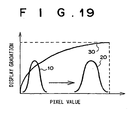
- a predetermined coefficient can be computed based on the statistical quantity refers to the obtaining of a coefficient according to, for example, the formula (1).
- the average value M, and the standard deviation ⁇ of the pixel values of any one of the obtained images are designated by desired constants a, b, and c:
- a display gradation of the brightness data of any one of the obtained images that has been multiplied by the computed coefficient refers to, as shown in Fig. 19 , by multiplying a pixel value distribution 10 by the coefficient, a pixel value distribution 20 is obtained, and according to a gradation processing function 30 representing a display gradation of the brightness data, a numerical value representing a brightness data is assigned to the value of this pixel value distribution 20.
- a gradation processing function representing the display gradation of the brightness data can be determined based on the statistical quantity, and based on the determined gradation processing function, a brightness data can be assigned to any one of the obtained images.
- a gradation processing function representing the display gradation of the brightness data can be determined based on the statistical quantity
- the expression "a gradation processing function representing the display gradation of the brightness data can be determined based on the statistical quantity" refers to, for example, when the pixel value distribution 10 of any one of the obtained images is as the distribution shown in Fig. 20 for the gradation processing function 30, the converting of the gradation processing function 30 to a gradation function 40.
- the expression "based on the determined gradation processing function, a brightness data can be assigned to any one of the obtained images" refers to the assigning of a numerical value representing a display gradation of the brightness data, according to the gradation processing function 40, to the pixel value distribution 10.
- the fluorescent-light image display apparatus comprises the features of claim 8.
- the computed-image is an image based on the ratio between a fluorescent-light image and a reflected-light image.
- the fluorescent-light image display apparatus can be provided with a statistical-quantity computing means for computing a statistical quantity of the pixel values of any one of the obtained images, and a gradation processing means for assigning, to any one of the obtained images of which a statistical quantity has been computed, a display gradation based on the statistical quantity.
- thestatistical-quantity computing means can be a means for computing the statistical quantity from a desired portion of any one of the obtained images.
- the gradation processing means can be a means for computing a predetermined coefficient based on the statistical quantity, multiplying any one of the obtained images of which the statistical quantity has been obtained by said computed coefficient, and assigning a display gradation of the brightness data to any one of the obtained images that has been multiplied by the coefficient.
- the gradation processing means can be a means for determining a gradation processing function representing the display gradation of the brightness data based on the statistical quantity, and assigning the display gradation of the brightness data, based on said determined gradation processing function, to any one of the obtained images.
- the fluorescent-light image display apparatus can be provided with a bit-shifting means for bit-shifting the pixel values of said one of the obtained images when each of said pixel values is represented by data of 9 bits or more, so that each of said pixel values is represented by the data of the first 8 bits or less, wherein the statistical-quantity computingmeans computes the statistical quantity based on said bit-shifted data.
- the expression "so that each of said pixel values is represented by data of 8 bits or less" refers to the rounding off of the bits following the first 8-bits of data representing a pixel value, so that the computing of a statistical quantity can be performed by a general-use statistical calculator.
- the gradation processing means can be a means capable of being turned ON/OFF.
- the expression “capable of being turned ON/OFF” refers to the capability of switching between the performing of gradation processing and the non-performing of gradation processing.
- the non-performing of gradation processing refers to, for example, if gradation processing is performed when brightness data has been assigned to the tissue-state image, regardless of whether the tissue-state is normal or diseased, the luminosity of the image will change, and it becomes impossible to judge the tissue state represented therein.
- the gradation processing means is capable of being switched OFF so as to avoid a large change to the display gradation of the brightness data of the image to be displayed.
- the composite-image forming means combines a tissue-state image and a tissue-form image to form a composite-image
- the composite-image is formed.
- the expression "when the number of pixels of both images differs, after converting the number of pixels of each of the two images to the number of pixels of either of the two images” refers to performing expansion processing, for example, when the number of pixels of one of the two images is 100 X 100 pixels and the number of pixels of the other is 500 X 500, by converting each pixel of the image having a number of pixels of 100 X 100 to a 5 X 5 unit of pixels, expanding the number of pixels of the 100 X 100 pixel image to a 500 X 500 pixel image matching the number of pixels of the counterpart image thereto.
- reduction processing can be performed; general image processing procedures can be used for aforementioned expansion processing and reduction processing.
- the fluorescent-light image display apparatus can be provided in the form of an endoscope apparatus having an endoscope insertion portion to be inserted into the body of a patient.
- a GaN type semiconductor laser can be used as the stimulating-light source, and the wavelength band of the stimulating-light made to be in the 400-420 nm range.
- the fluorescent-light image display apparatus can be combined with a means for obtaining and displaying a normal-image based on the reflected-light reflected from a target area upon irradiation thereof by a white-light reference light.
- color is divided into “color as conceived by the color intellect” and “color as perceived by the color visual sense”.
- color as conceived by the color intellect also called “sensory color” refers to the colors perceived by the human perceptual faculties, and which are qualitatively defined by use of symbols, color representation, etc.
- color as perceived by the color visual sense also called “color as a psychological physical quantity” is the standardized correlation between quantitatively defined physical quantities of a spectrum of light and the colors perceived as a psychological quantity and measurable in psychological testing.
- the color appearance system and the color mixing system are color specification systems for displaying color.
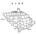
- the Munsell color system is a color specification system representative of a color appearance system. According to the Munsell color system, colors are defined by three properties: hue, (H) ; saturation (S) ; and brightness (v). Hue is divided into the three different colors of red (R), blue (B), and green (G) . First, there are five colors that are the base hues: R; yellow (Y); G; B; and purple (P) ; and these are distributed as five sectors of equal size around the circumference of a single hue ring such as that shown in Fig. 1 . Next, the intermediate hues YR, GY, BG, PB, and RP of the base hues are distributed.
- a reference number 5 is assigned to the base and intermediate hues, and although there are many cases in which there are 100 hues divided into groups of 10 used between adjacent hues, if a rotation angle from 5R, which is a base hue, is used, hues can be represented as continuous values.
- the luminosity Value V is a standard unit of measure defining the brightness of a color: an ideal black having a 100% reflectance is represented by a luminosity Value of 0; and an ideal white having a reflectance of 100% is represented by a luminosity Value of 10.
- the human sensory perception of brightness is not proportionate to the reflectance; for example, to recognize a reflectance of 20% as an intermediate brightness, the Munsell brightness standard is substantially proportional to the square root of the reflectance.
- the saturation (S) is a standard unit of measure defining the vividness of a color: the vividness is expressed for each brightness and hue by numerical values within a scale starting with gray, which has no vividness and is represented by a value of 0, to the monochrome colors, which are the most vivid.
- a saturation is created for each brightness of the hue represented at a distance from the center thereof, and if stacked concentrically in a circular form in order proceeding from the low level brightness's, the 3 properties occurring in the Munsell color system can be expressed as a tube-formed color body, as shown in Fig. 2 . All of the colors can be positioned at some point in this color body.
- sensory color is displayed as three-dimensional coordinate space having a one-dimensional brightness coordinate (called a brightness index), and a two-dimensional coordinate called a conceptual color degree representing an integrated hue and saturation.
- the CIE Commission International de l'Eclairage
- RGB Red, B (blue), and G (green)
- RGB Red, blue
- G green
- these three source stimuli, and the three source stimuli values that represent the mixing proportions of the three source stimuli comprise the RGB color specification system.
- the plotted equivalent color function may be a negative value according to the wavelength when the three source stimuli values formed by additively mixing continuous spectra of light, difficulty is encountered in function processing. Therefore, coordinate conversion processing is performed so that all of the equivalent color functions are advantageously converted into positive values, and a new color specification system, which defines three imaginary source stimuli X, Y, and Z (i.e., the XYZ color specification system) has been developed in relation to the RGB system.
- the XYZ color specification system in order to facilitate mathematical treatment, because the equivalent color function of Z (called the brightness) is defined so that it is the equivalent of a relative luminosity factor representing a sensitivity to the human eye with respect to the wavelength.
- Fig. 3 shows a chromaticity chart of the XYZ color specification system.
- a mixed color of two colors is represented by a point on the straight line connecting two chromaticity points representing the two colors. All the colors appear as points contained within the region def ined by a bell - formd curve (a spectra locus) and the straight line (a pure purple locus) connecting both ends thereof. Further, the arrow mark in center of Fig. 3 indicates the change in hue.
- the R,G,B components are not transferred as independent colors.
- the R,G,B components are converted, by use of a predetermined computation, to two color difference signals I,Q and one brightness signal Y.
- other systems representative of visible image signal systems such as the PAL system, etc.
- the method of and apparatus for displaying a fluorescent-light image according to the present invention in which the computed-image is based on the ratio between a fluorescent-light image and a reflected-light image, because a computed-image reflecting the emission output of the fluorescent-light emitted from the target area can be obtained, a composite-image accurately reflecting the tissue-state of the target area can be displayed.
- a statistical quantity is computed of the pixel values of any one of the obtained images, and a display gradation of the brightness data, based on the statistical quantity, is assigned to said any one of the obtained images, even if the pixel values of an image to which brightness data has been assigned are small, a composite-image already having a brightness above a predetermined value can be formed, and also, because the dynamic range of the display gradation of the brightness data can be virtually expanded, a composite-image already capable of visual recognition can be provided.
- the display gradation of the brightness data can be optimized, an also, the amount of computing required to compute the statistical quantity can be reduced.
- a predetermined coefficient can be computed based on the statistical quantity and aforementioned any one of the obtained images can be multiplied by the computed coefficient, and for cases in which a display gradation of the brightness data is to be assigned to an image that has been mul tiplied by the computed coefficient, an appropriate display gradation of the brightness data can be assigned by a simpler computation method.
- a gradation processing function representing the display gradation of the brightness data can be determined based on the statistical quantity, and for cases in which, based on the determined gradation processing function, a brightness data is to be assigned to any one of the obtained images, the display gradation of the brightness data occurring in a composite-image can be virtually expanded (an equalization effect) by a simpler computation method.
- the color data can be easily assigned to a tissue-state or a tissue-form image.
- the brightness data can be easily assigned to a tissue-state or a tissue-form image.
- the color data can be defined corresponding to a hue H occurring in the Munsell color system hue ring shown in Fig. 1 , and can easily be made to correspond to only a hue.
- the color data can be made to correspond to a pair of chromaticity coordinates (x,y) shown in the chromaticity chart in Fig. 3 , and can be easily made to correspond to only a chromaticity.
- a color-difference signal and a brightness signal can be determined from aforementioned computed-image, etc., and said color-difference signal and brightness signal canbe input directly into a video signal circuit, etc., and the color (color difference and brightness) of a composite-image can be determined.
- a bit shifting means is provided to shift the first 8 bits of data so that the pixel value is represented by 8 bits data or less.
- the statistical-quantity computing means computes the statistical quantity based on the bit-shifted pixel values, the computation can be performed by use of a general-use statistical calculator and high-speed computation processing can be attained.
- the computation of the statistical quantity can be performed comparatively easily, and a display gradation of an appropriate brightness can be assigned.
- the number of pixels of both images is different, after converting the number of pixels of both images to the number of pixels of either of the two images, because a composite-image is to be formed, after, for example, making the number of pixels of the image having fewer pixels match the number of pixels of the image having the larger number of pixels, for cases in which a composite - image is formed based on both images, because, for example, the quantity of fluorescent light is small, when the fluorescent-light image is obtained, it is necessary that the fluorescent-light image be subjected to binning processing, etc., and even for cases in which the number of pixels of the fluorescent-light image is less than the number of pixels of the reflected-light image, the number of pixels of the composite-image can be matched to the number of pixels of the reflected-light image and the composite-image displayed, and the tissue-state of the target area can be accurately displayed.
- the number of pixels of the image having the larger number of pixels is made to match the number of pixels of the image having fewer pixels, for cases in which a composite-image is to be formed based on both images, the need to perform excessive computation processing is eliminated and the image processing can be carried out at high-speed.
- a GaN type semiconductor laser is used as the stimulating-light source, a cost-effective small-sized light source can be provided, and also, if the wavelength band of the simulating light is in the 400-420 nm range, fluorescent light is efficiently emitted from a target area irradiated thereby.
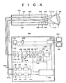
- FIG. 4 is a schematic drawing of a fluorescent endoscope apparatus implementing a fluorescent-light image display apparatus.
- the fluorescent light emitted from a living-tissue subject is two-dimensionally detected by an image fiber; a narrow-band fluorescent-light image having a wavelength band of 430-530 nm and a wide-band fluorescent-light image having a wavelength band of 430-730 nm are obtained; a computed-image based on the division value between the pixel values of both images is formed; a hue signal H determining a hue H occurring in the Munsell color system is assigned to said computed-image and a tissue-state image representing mainly the tissue-state of the target area is formed; an IR reflected-light image formed of the light reflected from the living-tissue subject under examination upon illumination thereof by white-light is obtained; a luminosity V occurring in the Munsell color system is assigned to said IR reflected-light image and a tissue-state image reflecting mainly the tissue-form of the target area is formed; and a composite-image combining the tissue-state image and the tissue-form
- the fluorescent endoscope apparatus comprises: an endoscope insertion portion 100 to be inserted into the body of the patient to the position at which the primary nidus of a disease and areas of suspected secondary infection are located; an illuminating unit 110 for emitting normal-image and IR reflected-light image obtaining-use white-light and fluorescent-light image obtaining-use stimulating-light; an image obtaining unit 120 for obtaining two fluorescent-light images having different wavelength bands and a reflected-light image; a composite-image forming unit 130 for computing a division value between the fluorescent-light images, assigning a hue to a computed- image based on said division value and forming a tissue-state image, assigning a luminosity V to the pixel values of an IR reflected-light image and forming a tissue-form image, and combining the tissue-state image and the tissue-form image to form a composite-image; an image processing unit 140 for performing the image processing required in order to display the normal-image and the composite-image as visible images; a control computer
- the endoscope insertion portion 100 comprises a light guide 101 extending to the forward end of the internal portion, a CCD cable 102, and an image fiber 103.
- the forward end portion of the light guide 101 and the CCD cable 102 that is, the forward end portion of the insertion portion, is provided with an illuminating lens 104 and an objective lens 105.
- the image fiber 103 is a silicon glass fiber, and is provided at the forward end thereof with a focusing lens 106.
- a CCD photographing element is connected to the forward end of the CCD cable 102, and a prism 108 is attached to said CCD photographing element 107.
- the light guide 101 is an integrated cable in which a white-light 101a formed of composite glass fiber and a stimulating-light guide 101b formed of silicon glass fiber are bundled, and the white-light guide 101a and the stimulating-light guide 101b are connected to the illuminating unit 110.
- One end of the CCD cable 102 is connected to the image processing unit 140, and one end of the image fiber 103 is connected to the image obtaining unit 120.
- the illuminating unit 110 comprises a white-light source 111 for emitting normal-image and IR reflected-light image obtaining-use white-light L1 and a white-light use power source 112 electrically connected to said white-light source 111, and a GaN type semiconductor laser 114 for emitting fluorescent-light image obtaining-use stimulating-light L2 and a semiconductor-laser use power source 115 electrically connected to said GaN type semiconductor laser 114.
- the image obtaining unit 120 comprises a stimulating-light cutoff filter 121 for cutting off light in the wavelength band below 420 nm, which is close to the wavelength band of the stimulating-light, from the fluorescent light L3 passing through the image fiber 103, a switching filter 122 composedof a combination of three types of optical filters, a filter rotating apparatus 124 for rotating said switching filter 122, a CCD photographing element 125 for obtaining a fluorescent-light image or an IR reflected-light image passing through said switching filter 122, an A/D converting circuit 126 for digitizing a fluorescent-light image and an IR reflected-light image obtained by the CCD photographing element 125, and an image memory 127 for storing an image signal thathas beendigitizedby theA/D converting circuit 126.
- the switching filter 122 is formed of anoptical filter 123a, which is a band-pass filter for transmitting light in the 430-730 nm wavelength range, an optical filter 123b, which is a band-pass filter for transmitting light in the 480 ⁇ 50 nmwavelength range, and an optical filter 123c, which is a band-pass filter for transmitting light in the 750-900 nm wavelength range.
- the optical filter 123a is a wide-band fluorescent-light image obtaining-use optical filter; the optical filter 123b is a narrow-band fluorescent-light image obtaining-use optical filter, and the optical filter 123c is an IR reflected-light image fluorescent-light image obtaining-use optical filter.
- the control computer 150 implements controls so that the optical filter 123a and 123b are alternately disposed above the optical path by the filter rotating apparatus 124.
- the CCD photographing element 125 is a 500 X 500 pixel obtaining element, and when obtaining an IR reflected-light image, under control of the control computer 150, normal readout is carried out, however, when obtaining a fluorescent-light image, because the signal of the fluorescent-light image is raised, binning readout is performed after outputs of 5 X 5 individual pixels are added. Therefore, when obtaining a fluorescent-light image, the image obtaining element operates as an image obtaining element having 100 X 100 pixels.
- the image memory 127 comprises a narrow-band fluorescent-light image memory zone, a wide-band fluorescent-light image memory zone, and an IR reflected-light image memory zone, which are not shown in the drawings.
- the narrow-band fluorescent-light image obtained when the living-tissue subject is irradiated by the stimulating-light L2 and in a state in which the narrow-band fluorescent-light image obtaining-use optical filter 123a is disposed above the optical path is stored in the narrow-band fluorescent-light image memory zone
- the wide-band fluorescent-light image obtained when the living-tissue subject is irradiated by the stimulating-light L2 and in a state in which the wide-band fluorescent-light image obtaining-use optical filter 123b is disposed above the optical path is stored in the wide-band fluorescent-light image memory zone.
- the IR reflected-light image obtained when the living-tissue subject is illuminated with the white-light L1 and in a state in which the IR reflected-light image obtaining-use optical filter 123c is disposed above the optical path is stored in the IR reflected-light image obtaining-use image memory zone.
- the number of pixels of the IR reflected-light image is 500 X 500
- the number of pixels of the narrow-band fluorescent-light image and the wide-band fluorescent-light image is 100 X 100.
- the image composing unit 130 comprises a tissue-state image forming means 131 provided with a prerecorded look-up table correlating the range of division value between the fluorescent-light images and the hue H occurring in the Munsell hue ring (0 rad - 2/3 rad, Red-Yellow-Green range) for assigning a hue H to the computed image and forming a tissue-state image, a tissue-form image forming means 132 provided wi th a prerecorded look-up table correlating the pixel value range of an IR reflected-light image and a luminosity V (Value) occurring in the Munsell color system, and an composite-image forming means 133 for forming a composite-image based on the tissue-state image and the tissue-form image.
- a tissue-state image forming means 131 provided with a prerecorded look-up table correlating the range of division value between the fluorescent-light images and the hue H occurring in the Munsell hue ring (0 rad - 2/3 rad, Red
- the image processing unit 140 comprises a signal processing circuit 141 for forming a normal-image, which is a color image, from the signal obtained by the CCD photographing element 107, an A/D converting circuit 142 for digitizing the normal-image obtained by said signal processing circuit 141, a normal-image memory 143 for storing the digitized normal-image, and a video signal processing circuit 144 for converting to a video image signal the normal-image output from said normal-image memory 143 and the composite-image composed by the image composing portion 143.
- a signal processing circuit 141 for forming a normal-image, which is a color image, from the signal obtained by the CCD photographing element 107
- an A/D converting circuit 142 for digitizing the normal-image obtained by said signal processing circuit 141
- a normal-image memory 143 for storing the digitized normal-image
- a video signal processing circuit 144 for converting to a video image signal the normal-image output from said normal-image memory 143 and the composite-image
- the operation of a fluorescent endoscope apparatus of the configuration described above and implementing the fluorescent-light image display apparatus will be described.
- the obtaining of a normal-image and an IR reflected-light image, and the obtaining of a fluorescent-light image are performed alternately in a time division manner.
- the operation occurring when a fluorescent-light image is to be obtained will be explained.
- the semiconductor-laser use power source 115 is activated, and stimulating-light L2 having a wavelength of 410 nm is emitted from the GAN type semiconductor laser 114.
- the stimulating-light L2 passes through the stimulating-light use focusing lens 116 and enters the stimulating-light guide 101b, and after being guided to the stimulating-light emitting end of the endoscope insertion portion, the white-light L1 is projected onto the living-tissue subject 50 by illuminating lens 104.
- the fluorescent light L3 emitted from the living-tissue subject 50 upon irradiation thereof by the stimulating-light L2 is focused by lens 106 and enters the forward end of the image fiber 103. After passing through the image fiber 103, the fluorescent light L3 is focused by the lens 128 and passes through the stimulating-light cutoff filter 121, the switching filter 122 and the optical filters 123a and 123b.
- the optical filter 123a is a band-pass filter that transmits only light in the 430-730 nmwavelength range, and the fluorescent transmitted by the optical filter 123b becomes a wide-band fluorescent-light image.
- the optical filter 123b is a band-pass filter that transmits only light in the 480 ⁇ 50 nm wavelength range, and the fluorescent transmitted by the optical filter 123b becomes a narrow-band fluorescent-light image.
- the wide-band fluorescent-light image and the narrow-band fluorescent-light image are received by the CCD photographing element 125, and after being electrically converted, 5 X 5 pixel signal portions are readout using a binning readout process, said wide-band and narrow-band fluorescent-light images are digitized by the A/D converting circuit and stored in the wide-band fluorescent-light image memory zone and the aarrow-band fluorescent-light image memory zone, respectively, of the image memory 127.
- a fluorescent-light image having a weak light strength can be obtained with a high degree of accuracy, however, the number of pixels of the fluorescent-light image becomes 100 X 100, which is 1/25 the number of when normal readout is performed.
- the white-light use power source 112 is activated based on a signal from the control computer 150, and the white-light L1 is emitted from the white-light source 111.
- the white-light L1 passes through the white-light use focusing lens 113 and enters the white-light guide 101a, and after being guided to the stimulating-light emitting end of the endoscope, insertion portion, the white-light L1 is projected onto the living-tissue subject 50 by an illuminating lens 104.
- the reflected-light L4 of the white-light L1 is focused by the focusing lens 106 and enters the forward end of the image fiber 103. After passing through the image fiber 103, the reflected-light L4 is focused by the lens 128 and is transmitted by the stimulating-light cutoff filter 121, the switching filter 122, and the optical filter 123c.
- the optical filter 123c is a band-pass filter that transmits only light in the 750-900 nm wavelength range, the IR reflected-light image transmitted by the optical filter 123c becomes an IR reflected-light image composed only of the near-infrared wavelength light within the reflected-light L4 transmitted by the optical filter 123c.
- This IR reflected-light image is received and electrically converted by the CCD photographing element 125, and after being digitized by the A/D converting circuit 126, is stored in the IR reflected-light image memory zone of the image memory 127.
- the tissue-state image forming means 131 of the composite-image forming unit 130 divides the pixel value of each of the pixels of the narrow-band fluorescent-light image stored in the narrow-band fluorescent-light image memory zone of the image memory 427 by the corresponding pixel value each of the pixels of the wide-band fluorescent-light image stored in the wide-band fluorescent-light image memory zone of the image memory 427, assigns a hue H (Hue) occurring in the Munsell color system, by use of the division value and the prerecorded look-up table, and forms a tissue-state image, which is output to the image composing portion 133.
- H Hue
- the tissue-form image forming means 132 assigns a luminosity V occurring in the Munsell color system, by use of the pixel value and the prerecorded look-up table, for each pixel of the IR reflected-light image stored in the IR reflected-light image memory zone of the image memory 127, and forms a tissue- state image, which it outputs to the image composing portion 133.
- the image composing portion 133 converts the data of 1 pixel of a tissue-state image to the data of a 5 X 5 pixel portion and expands the number of pixel's of a 100 X 100 pixel tissue-state image to 500 X 500 pixels, and afterwards, combines said 500 X 500 pixel tissue-state image and the tissue-state image based on the luminosity V and forms a composite-image.
- hue, brightness and saturation three attributes of color
- the saturation occurring in the Munsell color system is set at the highest value of each hue and brightness when composing a composite-image.
- RGB conversion is preformed using the formula below, and the composite-image formed is output to the video signal processing circuit 144:
- R V / 3 + 2 ⁇ S cos H / 6
- G V / 3 - S cos H / 6 + S sin H / 2
- B V / 3 - S cos H / 6 - S sin H / 2
- the composite-image converted to a video signal by the video signal processing circuit 144 is input to the monitor 170 and displayed on said monitor as a visual image.
- the continuous operation described above are controlled by the control computer 150.
- the white-light use power source 112 is activated and the white-light L1 is emitted from the white-light source 111.
- the white-light L1 enters the white-light guide 101a through by way of the white-light use focusing lens 113, and after being guided to the stimulating-light emitting end of the endoscope insertion portion, is projected onto the living-tissue subject 50 by the illuminating lens 104.
- the reflected-light L4 of the white-light L1 is focused by the objective lens 105, reflected by the prism 108 and focused by the CCD photographing element 107.
- the visible image signal from the CCD photographing element 107 is input to the A/D converting circuit 142, and after being digitized, is stored in the normal-image memory 143.
- the normal-image stored in the normal-image memory 143 after being converted to a video signal by the video signal processing circuit 144, is input to the monitor 160 and displayed on said monitor 160 as a visible image.
- the continuous operation described above is controlled by the control computer 150.
- the hue of the displayed composite-image reflects the division value of the pixel values between two types of fluorescent-light images, that is, the difference in the form of the fluorescent spectra emitted from the living-tissue subject 50, and because the luminosity reflects the pixel values of the IR reflected-light image, that is, the form of the living-tissue subject 50, the data relating to the fluorescent light emitted from the living-tissue subject 50 as well as the data relating to the form of the living-tissue subject of the target area can be displayed in one image, and no doubt as to the reliability of the composite-image for use in diagnosis is imparted to an operator. Therefore, an operator can easily judge the tissue-state of the target area.
- the division value of the pixels values can be made to correspond only to the hue, and the precise difference in the form of the fluorescent spectra of the fluorescent light can be reflected in a composite-image.
- the number of pixels forming the fluorescent-light image is 100 X 100 pixels, however, when forming a composite-image, the dataof 1 pixel of a tissue- state image is converted into the data of a 5X 5 portion of pixels and the 100 X 100 pixels of the tissue-state image are expanded to 500 X 500 pixels. Then, because a composite-image has been formed by combining said 500 X 500 pixel tissue-state image and a tissue state image formed based on the luminosity V, the number of pixels of the display image corresponds to 500 X 500 pixels, and the form of the target area can be displayed so as to be clearly distinguishable.
- the stimulating-light can be emitted from a small-sized, cost-effectivestimulating-lightsource.
- the wavelength of the stimulating-light is 410 nm, fluorescent light is efficiently emitted from the living-tissue subject 50.
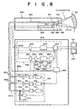
- FIG. 6 is a schematic drawing of a fluorescent endoscope apparatus implementing the fluorescent-light image obtaining apparatus. Note that for the current embodiment, the components shared in common with the first exemplary embodiment are labeled with the same reference numerals, and where further explanation thereof is not particularly required, it has been omitted.
- the fluorescent endoscope apparatus comprises an endoscope insertion portion 100 to be inserted into the body of a patient near the position at which the primary nidus of a disease and areas of suspected secondary infection are located, an illuminating unit for emitting normal-image and IR reflected-light image obtaining-use white-light and fluorescent-light image obtaining-use stimulating-light, a image obtaining unit 300 for obtaining two types of fluorescent-light images having different wavelength bands and a reflected-light image, a composite-image forming unit 400 for computing a division value between the fluorescent-light images, assigning a hue to a computed-image based on the division value and forming a tissue-state image, assigning a luminosity V to the pixel values of an IR reflected-light image and forming a tissue-state image, and combining each of said two tissue-state images to form a composite-image, an image processing unit 500 for performing the image processing required in order to display the normal-image and the composite-image as a visible image
- the image obtaining unit 300 comprises a stimulating-light cutoff filter 302 for cutting off light in the wavelength band below 420 nm, which is close to the wavelength band of the stimulating-light, from the fluorescent light L3 passing through the image fiber 103, a switching filter 303 composed of a combination of three types of optical filters, a filter rotating apparatus 304 for rotating said switching filter 303, a CCD photographing element306forobtaining afluorescent-light image passing through said switching filter 303 or an IR reflected-light image, and an A/D converting circuit 307 for digitizing the signal obtained by the CCD photographing element 306.
- the switching filter 303 which is the same as in the first embodiment, is formed of three types of optical filters: an optical filter 303a, which is a wide-band fluorescent-light image band-pass filter for transmitting light in the 430-730 nmwavelength range, an optical filter 303b, which is a narrow-band fluorescent-light image band-pass filter for transmitting light in the 430-530 nm wavelength range, and an optical filter 303c, which is an IR reflected-light image band-pass filter for transmitting light in the 750-900 nm wavelength range.
- an optical filter 303a which is a wide-band fluorescent-light image band-pass filter for transmitting light in the 430-730 nmwavelength range
- an optical filter 303b which is a narrow-band fluorescent-light image band-pass filter for transmitting light in the 430-530 nm wavelength range
- an optical filter 303c which is an IR reflected-light image band-pass filter for transmitting light in the 750-900 nm wavelength range.
- the image composing unit 400 comprises fluorescent-light image memory 401 for storing the digitized fluorescent-light image signal data of the fluorescent-light image composed of two different wavelength bands, an IR reflected-light image memory 403 for storing the IR reflected-light image signal data, a tissue-state image forming means 402 for performing computations according to the ratio of each pixel value of the fluorescent-light image composed of two different wavelength bands stored in the fluorescent-light image memory 401 and assigning a hue H to the computed value of each pixel value and forming a tissue-state image, a bit shifting means 409 for shifting the bit value of each pixel value represented by 9 bits of data or more from among the pixel values of the IR reflected-light image stored in the IR reflected-light image memory 403 so that each pixel value is represented by data of 8 bits or less, a statistical-quantity computing means 404 provided with an 8 bit statistical quantity calculator for computing a predetermined statistical quantity of each pixel value output from the bit shifting means 409, a coefficient computing means 405
- the fluorescent-light image data having two different wavelength bands is stored in the fluorescent-light image memory 401 and the IR reflected-light image data is stored in the IR reflected-light image memory 403, however, the fluorescent-light image memory and the IR reflected-light image memory can be made to be a common memory for storing both types of image data.
- the common memory can comprise a narrow-band fluorescent-light image memory zone, a wide-band fluorescent-light image memory zone and an IR reflected-light image memory zone, and a fluorescent-light image transmitted by the optical filter 303a is stored in-the wide-band fluorescent-light memory zone, a fluorescent-light image transmitted by the optical filter 303b is stored in the narrow-band fluorescent-light image memory zone, and an IR reflected-light image transmitted by the optical filter 303c is stored in the IR reflected-light image memory zone.
- the image processing unit 500 comprises an A/D converting circuit 501 for digitizing the normal-image obtained by the CCD photographing element 107, a normal-image memory 502 for storing the digitized normal-image, and a video signal processing circuit 503 for converting to a video signal the image signal output from said normal-image memory 502 and the composite-image output by the composite-image forming means 408.
- the operation of a fluorescent endoscope apparatus of the configuration described above and implementing the fluorescent-light image display apparatus will be described.
- the obtaining of a normal-image and an IR reflected-light image, and the obtaining of a fluorescent-light image can be performed alternately in a time division manner; however, because the operation occurring when a fluorescent-light image is obtained and the operation occurring when a normal-image and an IR reflected-light image are to be obtained are the same as in the embodiment described above, an explanation thereof has been omitted, and the operation occurring when a composite- image is to be formed, which is different from that occurring in the first embodiment described above, is explained.
- the wide-band fluorescent-light image and the narrow-band fluorescent-light image that have been obtained by the CCD photographing element 306 of the image obtaining unit 300 and digitized are stored in the fluorescent-light image memory 401.
- the wide-band fluorescent-light image that has been obtained by the CCD photographing element 306 is stored in the wide-band fluorescent-light image memory zone (not shown) of the fluorescent-light memory 401 and the narrow-band fluorescent-light image that has been obtained by the CCD photographing element 306 is stored in the narrow-band fluorescent-light memory zone (not shown) thereof.
- the IR reflected-light image obtained by the same CCD photographing element 306 of the image obtaining unit 300 is stored in the IR reflected-light image memory 403.
- the tissue-state image forming means 402 computes the ratio of each pixel value of the narrow-band fluorescent-light image to the corresponding pixel value of the wide-band fluorescent-light image, each image being stored in the fluorescent-light image memory 401, and forms a computed-image is formed.
- a hue H is assigned to the pixel values of said computed-image, and a tissue-state image is formed and output.
- the statistical-quantity computing means 404 computes the average value M and the standard deviation ⁇ of each pixel value. Then, the average value M and the standard deviation ⁇ are output to the coefficient computingmeans 405.
- the coefficient C is determined by the coefficient computing means according to the formula (2) below.
- Each pixel value of the IR reflected-light image is multiplied by the coefficient C by the coefficient multiplying means 406, and each computed value of each pixel is output to the tissue-form image forming means 407.
- the tissue-form image forming means 407 assigns a display gradation of the brightness to the computed value of eachpixel, and forms and outputs a tissue-form image.
- the tissue-state image output from the tissue-state image forming means 402 and the tissue-form image output from the tissue-form image forming means 407 are combined and output by the composite-image forming means 408.
- the composite-image converted to a video signal by the video signal processing circuit 503 is input to the monitor 602 and displayed thereon as a visible image.
- the continuous operation described above is controlled by the control computer 150. Note that other operations are the same as those occurring in the first embodiment.
- the processing can be carried out in a series of operations wherein the tissue-state image is formed, and then, after the tissue-form image is formed, the two images are combined, or alternatively, in parallel operations wherein the tissue-state image and the tissue-form image are formed at the same time, after which the two images are combined.
- the processing is performed in a parallel series, the operation can be completed faster.
- the gradation processing occurring in the second embodiment be capable of being switched ON/OFF.
- a coefficient c can be obtained as in the formula (3), for example.
- the statistical quantity computed by the statistical quantity computing means 404 not be based on an IR reflected-light image obtained in real-time in the same frame, and can be based on an IR reflected-light image obtained in the previous frame.
- the fluorescent endoscope apparatus of the second embodiment because a statistical value of the pixel values of an IR reflected-light image is computed and a display gradation of the brightness is assigned based on said statistical quantity, even for cases in which the pixel values of an image to which brightness data are small, a composite-image already having a brightness above a predetermined value can be formed, and also, because the dynamic range of the display gradation of the brightness data can be virtually expanded, a composite-image already capable of visual recognition can be provided.
- a fluorescent endoscope apparatus implementing a fluorescent-light image obtaining apparatus implementing the fluorescent-light image display method.
- the forming of the tissue-form image is performed in the same way as in the first and second embodiments described above, that is, a luminosity V is assigned to a reflected-light image and a tissue-form image is formed.
- a luminosity V is assigned to a reflected-light image and a tissue-form image is formed.
- the composite-image formed according to the current embodiment is displayed based on the three color attributes, the image is displayed with the colors within the color range show in the perspective view of Fig. 7 .
- the hue is green (an appropriate hue can be used) : for a normal tissue located at a position in which the distance from the stimulating-light emitting end of the endoscope insertion portion to the target area is close, the green is displayed bright and vivid; for a normal tissue located at a position wherein said distance is far, the green is displayed dark and vivid; foradiseased tissue located at a position wherein said distance is close, the toneless bright white is displayed; and for a diseased tissue located at a position wherein said distance is far, the toneless black is displayed.
- Other structures and operations are the same as those occurring in the first or second embodiments.
- the white-light source 111 is a multi-purpose light source for emitting both normal- image use white-light and reference light
- a configuration in which a separate light source is provided for each respective type of light can also be adopted.
- a computed-image has been computed based on the ratio between the narrow-band fluorescent-light image and the wide-band fluorescent-light image
- the computed-image can also be computed based on the ratio of the narrow-band fluorescent-light image and the reflected-light image as defined by the present invention.
- the use of a computed-image can be forgone, and a hue or saturation assigned to the fluorescent-light image itself.
- the CCD photographing element is a multi-purpose obtaining element for obtaining fluorescent-light images and reflected-light images, however, a separate obtaining element for obtaining each type of image may also be provided. Also, a separate CCD photographing element can be provided for obtaining the wide-band fluorescent-light images and the narrow-band fluorescent-light images, respectively.
- FIG. 8 is a schematic drawing of a fluorescent endoscope apparatus according to the fourth exemplary embodiment.
- a normal-image is obtained by a CCD photographing element 156 of the reflected-light reflected from a target area upon irradiation thereof by an area-order light (Lr, Lg, Lb), and the normal-image is displayed on a monitor 161.
- a narrow-band fluorescent-light image and a wide-band fluorescent-light image are obtained by a CCD photographing element 156 based on the fluorescent-light emitted from a target area upon irradiation thereof by a stimulating-light, and based on the division value of both of said fluorescent-light images pairs of chromaticity coordinates (x,y) occurring in the XYZ color specification system are assigned thereto and a tissue-state image is formed.
- An IR reflected-light image is obtained of the reflected-light reflected from a target area upon irradiation thereof by a reference-light and a saturation z is assigned thereto based on the pixel values thereof, and a tissue-form image is formed.
- a composite-image based on the tissue-state image and the tissue-form image is displayed on a monitor 162.
- the fluorescent endoscope apparatus comprises: an endoscope insertion portion 350, provided with a CCD photographing element 156 at the forward end thereof, to be inserted into the body of a patient where the primary nidus and suspected areas of secondary infection are located; an illuminating unit 310 for emitting area-order light (red light Lr, green light Lg, blue light Lb), which is normal-image obtaining-use illuminating light, stimulating-light L2, which is fluorescent-light image obtaining-use stimulating-light, and reference light L5, which is IR reflected-light image obtaining-use reference light; a composite-image forming unit 330 for computing a division value between said fluorescent-light images, assigning a chromaticity (hue and saturation) to a computed-image based on said division value and forming a tissue-state image, for assigning a brightness Z to the pixel values of the IR reflected-light image and forming a tissue-form image, and for combining the tissue-state image and the
- the endoscope insertion portion 350 comprises a light guide 351 extending to the forward end thereof and a CCD cable 352, and an objective lens 155 is provided at the forward end of the CCD cable 352.
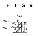
- a CCD photographing element 156 having an on-chip mosaic filter 354 composed of a group of microscopic band-filters is connected to the forward end of the CCD cable 352, and a prism 157 is attached to said CCD photographing element 156.
- the light guide 351 is an integrated cable containing a light guide 351a for the area-order guide, a stimulating-light use light guide 352b, and a reference-light use light guide 351c bundled together, and each of said light guides is connected to the illuminating unit 310.
- the CCD cable 352 is includes an activation line 353a for transmitting the CCD photographing element activation signal and an output line 353b for reading out the signal from the CCD photographing element 156; one end of the activation line 353a is connected to the control computer 360, and one end of the output line 353b is connected to the composite-image forming unit 330 and the image processing unit 340.
- the mosaic filter 354 is composed of narrow-band filters 354a for transmitting light in the 430-530 nm wavelength band and all-wavelength band filters 354b for transmitting light of all wavelengths, grouped alternately thereon, and each of the narrow-band filters is in a one-to-one correspondence to the pixels of the CCD photographing element 156.
- the illuminating unit 310 comprises a white-light source 111 for emitting white-light and a white-light source use power source 112 electrically connected to said white-light source 111, a switching filter 314 for switching in order to separate the white-light into R-light Lr, G-light Lg, and B-light Lb, a filter rotating portion 315 for rotating the switching filter 314, a GaN type semi conductor laser 211 for emitting fluorescent-light image obtaining-use stimulating-light L2 and a semiconductor-laser-use power source 212 electrically connected to said GaN semiconductor laser 211, a reference-light source 311 which is a semiconductor laser for emitting IR reflected-light image obtaining-use reference light L5 and a semiconductor-laser use power source 312 electrically connected to said reference-light source 311.
- the switching filter 31 is provided with a R light transmitting R filter 314a, a G light transmitting filter 314b, a B light transmitting filter 314c, and a mask portion 314d having a light-cutoff function.
- the composite-image forming unit 330 comprises: an A/D converting circuit 331 for digitizing the image signal obtained by the CCD photographing element 156 when a target area is irradiated by stimulating-light L2 or reference light L5; and image memory 332 composed of different memory zones for storing a narrow-band fluorescent-light image received at the pixels corresponding to the narrow-band filter 354a of the mosaic filter when the stimulating-light L2 is emitted, a wide-band fluorescent-light image received at the pixels corresponding to the all-wavelength bands filter 354b of the mosaic filter when the stimulating-light L2 is emitted, and a reflected-light image received at the pixels corresponding to the all-wavelength bands filter 354b of the mosaic filter when the reference light L5 is emitted; a tissue-state image forming means 333 for computing a division value between a narrow-band fluorescent-light image and a wide-band fluorescent-light image at the adjacent pixels stored in the image memory 332 and assigning a pair of chromaticity coordinate
- a lookup-table correlating the division values of fluorescent-light images and the chromaticity coordinates (x,y) occurring in the XYZ color specification system has been pre-recorded in the tissue-state image forming means 333.
- aforementioned division value which has been converted to a 16-bit value having no reference number
- the chromaticity coordinates (x,y) shown in Fig. 3 which are the coordinates of a spectra locus of red (650 nm), yellow and green (520 nm) range, are correlated as shown in Table 2.
- the image processing unit 340 is provided with an A/D converting circuit 342 for digitizing the image signal corresponding to the pixels of the wide-band filter 354b of the mosaic filter 354 when R-light Lr, G-light Lg or B-light Lb is irradiated, a normal-image memory 343 for storing each color of a digitized normal-image, a video signal processing circuit 344 for converting to a video signal the three-color image signals of matched phases read out from said normal-image memory 343 when a normal - image is to be displayed and outputting said video signal, and also for converting to a video signal the composite- image output from the composite-image forming unit 330 when a fluorescent-light image is to be displayed and outputting said video signal.
- A/D converting circuit 342 for digitizing the image signal corresponding to the pixels of the wide-band filter 354b of the mosaic filter 354 when R-light Lr, G-light Lg or B-light Lb is irradiated
- the obtaining of a normal-image, an IR reflected- light image, and a fluorescent-light image is performed in time-division manner, and a normal-image is displayed on the monitor 161 and a composite-image based on the fluorescent-light L3 and the reflected-light L4 is displayed on the monitor 162.
- the red light Lr, green light Lg, blue light Lb, stimulating-light L2 and reference light L5 are emitted from the illuminating unit in order.
- the semiconductor-laser use power source 212 is activated and stimulating-light L2 having a wavelength of 410 nm is emitted from the GaN-type semiconductor laser 211.
- the stimulating-light L2 is transmitted by a lens 213 and enters the stimulating-light use light guide 351b, and after being guided to the stimulating-light emitting end of the endoscope insertion portion, the stimulating-light L2 is projected onto a target area 50 by an illuminating lens 154.
- the fluorescent-light emitted from the target area upon irradiation thereof by the stimulating-light L2 is focused by a focusing lens 155, reflected by a prism 157, transmitted by the mosaic filter 354 and focused on the CCD photographing element 156 as a fluorescent-light image. Because the reflected stimulating-light L2 occurring at this time id cutoff by a stimulating-light cutoff filter 355, it does not enter the CCD photographing element 156.
- the image signal photoelectrically converted by the CCD photographing element 156 is digitized by the A/D converting circuit 331 of the composite-image forming means 330, separated into a narrow-band fluorescent-light image transmitted by the narrow-band filter 354a and a wide-band fluorescent-light image transmitted by the wide-band filter 354b, and each of said fluorescent-light images are stored in the corresponding memory zones of the image memory 332.
- the reference-light use power source 312 is activated and reference-light L5 is emitted from the reference-light source 311.
- the reference-light L5 is transmitted by a lens 313 and enters the reference-light use light guide 351c, and after being guided to the stimulating-light emitting end of the endoscope insertion portion, the reference-light L5 is projected onto a target area 50 by an illuminating lens 154.
- the reflected-light L6 reflected by the target area 50 upon irradiation thereof by the reference-light L5 is focused by the focusing lens 155, reflected by the prism 157, transmitted by the mosaic filter 354, and focused on the CCD photographing element 156 as an IR reflected-light image.
- the image signal photoelectrically converted by the CCD photographing element 156 only the signal of the light received at the pixels corresponding to the all-wavelength bands filter 354b is digitized by the A/D converting circuit 331 of the composite-image forming unit 330 and stored in a different memory zone of the image memory 332 from the fluorescent-light images described above as an IR reflected-light image.
- each pixel value of the narrow-band fluorescent-light image is divided by the corresponding pixel value of the wide-band fluorescent-light image, and the division value of each pixel ⁇ is converted to a 16-bit data not having a reference number. Then, a pair of chromaticity coordinates occurring in the XYZ color specification system is assigned to each pixel referring to the pre-recorded lookup-table, and a tissue-state image is formed and output to the composite-image forming means 233.
- the tissue-form image forming means 338 assigns, based on said changed gradation processing function, a display gradation of a brightness Z occurring in the XYZ color specification system to each pixel value of the IR reflected-light image and forms a tissue-form image, and outputs said formed tissue-form image.
- the composite-image forming means 334 combines the tissue-state image and the tissue-form image based on the brightness Z to form a composite-image.
- the RGB is converted and the composite-image is formed and output to the video signal processing circuit 344:
- R 0.41844 ⁇ X - 0.15866 ⁇ Y - 0.08283 ⁇ Z
- G 0.09117 ⁇ X + 0.25242 ⁇ Y + 0.01570 ⁇ Z
- the composite-image converted to a video signal by the video signal converting circuit 344 is input to the monitor 162 and displayed thereon as a visual image.
- the continuous operation described above is controlled by the control computer 360.
- a color difference signal IQ is assigned to a computed-image and a tissue state image is formed and a brightness signal Y is assigned to an IR reflected-light image and a tissue-form image is formed
- a color difference signal IQ determined from the tissue-state image and a brightness signal Y determined from the IR reflected-light image can be input directly into the video signal processing circuit 344, the necessity to form an RGB signal is eliminated, and the configuration of the apparatus can be simplified.
- the target area 50 is irradiated with R light Lr, and the reflected R light Lr reflected form the target area 50 is focused on the CCD photographing element 156 as a R light reflected-light image.
- the R-light image signal received at the pixels corresponding to the all-wavelength bands filter 354, from among the signal output from the CCD photographing element 156, is digitized by the A/D converting circuit and stored in the R-light image signal memory zone of a normal- image memory 343. Subsequently, by the same operation, a G-light image signal and a B-light image signal are obtained, and each is stored in the G-light image signal memory zone and the B-light image signal memory zone of the normal-image memory, respectively.
- the three colored image signals are stored in the normal - image memory 343, the three colored image signals are output with matched phases and timings to the video signal processing circuit, where they are converted to a video signal.
- the video signal is output to the monitor 161 and displayed thereon as a color image.
- an XYZ color spaced has been used as the color space
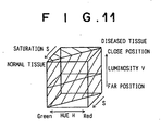
- an HSV color space can be used as the color space; for example, for cases in which a hue and a saturation are assigned to a computed-image and a tissue-state image is formed, a composite-image will be displayed according to the range of colors shown in the perspective potion of Fig. 11 .
- a normal tissue in a target that is located at a close distance from the stimulating- light emitting end of the endoscope insertion portion 100 will be displayed as a bright, vivid green; when said distance is far, a normal tissue is displayed as a dark, vivid green; a diseased tissue is displayed as a bright toneless red when said distance is close; and a diseased tissue is displayed as a dark, toneless red when said distance is far.
- a saturation a method the opposite of that described above can be applied, that is, a low saturation can be assigned to a normal tissue and a high saturation can be assigned to a diseased tissue. In this case, when diagnosis is performed, a diseased tissue can be more accurately detected.
- the gradation processing occurring in the fourth embodiment described above is capable of being switched ON/OFF.
- the gradation processing function can be rewritten such that, for example, given the largest pixel value max, the smallest pixel value min of the pixel values of an IR reflected-light image, and desired constants ⁇ and ⁇ : ⁇ max + min / 2 + ⁇ X max - min / 2 is the lower limit of the display gradation of the brightness, and ⁇ max + min / 2 - ⁇ X max - min / 2 is the upper limit of the display gradation of the brightness.
- a fifth exemplary embodiment of a fluorescent endoscope apparatus implementing the fluorescent-light image display apparatus will be explained.
- the forming of a tissue-state image occurring in the first through the fourth embodiments, wherein a hue H or chromaticity (hue and saturation) have been assigned to a computed-image based on the division value between a narrow-band fluorescent-light image and a wide-band fluorescent-light image and a tissue-state image formed is performed such that a luminosity V (brightness Z) is assigned to the computed-image and a tissue-state image is formed, which is combined with the tissue- form image to form a composite- image which is then displayed.
- the tissue - form image can be formed in the same way as in the first through the fourth embodiments, that is, by assigning a luminosity V (brightness Z) to the reflected - light image and forming a tissue-form image.
- V luminosity
- the composite-image formed according to the current embodiment represents three colors
- the composite-image is displayed in the range color indicated by the thick arrow mark in Fig. 12 .
- the hue is green (an appropriate hue can be used), for example: a normal tissue in a target that is located at a close distance from the stimulating-light emitting end of the endoscope insertion portion 100 will be displayed as a bright green; when said distance is far, a normal tissue is displayed as a dark green; a diseased tissue is displayed as a dark green when said distance is close; and a diseased tissue is displayed as a dark green when said distance is far.
- Other structures and operations are the same as those of the first through the fourth embodiments.
- FIG. 13 is a schematic drawing of a fluorescent endoscope apparatus implementing the fluorescent-light image display apparatus according to the present invention. Note that the elements of the current embodiment shared in common with the fourth embodiment have been given the same reference numbers, and in so far as it is not particularly required, further explanation thereof has been omitted.
- the light reflected from a target area upon irradiation thereof by an area-order light (R light Lr, G light Lg, and B light Lb) is obtained as a normal-image by the CCD - photographing element 156 and displayed on the monitor 161
- a wide-band fluorescent-light image based on the fluorescent-light emitted from a target area upon irradiation thereof by the stimulating-light is obtained by the CCD photographing element 156.
- the reflected-light L7 reflected from a target area 50 upon irradiation thereof by the R-light is obtained as an IR reflected-light image.
- a computed- image is computed based on the division value between the wide-band fluorescent-light image and the IR reflected-light image, and a hue H is assigned based on the pixel values of the computed-image and a tissue-state image is formed.
- a saturation S and a luminosity V are assigned based on the brightness of the pixel values of the IR reflected - light image and a tissue-form image is formed, and a composite-image based on the tissue-state image and the tissue-form image is displayed on the monitor 162.
- the fluorescent endoscope apparatus comprises a CCD photographing element 156 disposed a the stimulating-light emitting end thereof, an endoscope insertion portion to be inserted into a patient's body where the primary nidus and areas of suspected secondary infection are located, an illuminating unit 370 for emitting normal-image obtaining-use illuminating light and reference light, which is area-order color (Lr, Lg, Lb), and fluorescent-light image obtaining-use stimulating-light L2, a composite-image forming unit 380 for computing a division value between aforementioned wide-band fluorescent-light image and an IR reflected-light image, assigning a chromaticity (hue and saturation) to a computed-image based on said division value and forming a tissue-state image, for assigning a saturation and a luminosity to the pixel values of the IR reflected-light image and forming a tissue-form image, and for combining the tissue-state image and the tissue-form image to form a
- the light guide 351 is an integrated cable containing a light guide 351a for the area-order guide, and a stimulating-light use light guide 352b bundled together, and each of said light guides is connected to the illuminating unit 370.
- the illuminating unit 370 comprises a white-light source 111 for emitting white-light and a white-light source use power source 112 electrically connected to said white-light source 111, a switching filter 314 for switching in order the separate the white light into R - light, G-light, B-light, a filter rotating portion 315 for rotating the switching filter 314, and a GaN type semiconductor laser 211 for emitting fluorescent-light image obtaining-use stimulating-light L2 and a semiconductor-laser use power source 212 electrically connected to said GaN semiconductor laser 211.
- the composite-image forming unit 380 comprises: an A/D converting circuit 381 for digitizing the image signal obtained by the CCD photographing element 156 when a target area is irradiated by stimulating-light L2 or R-light Lr; and image memory 382 composed of differentmemory zones for storing a wide-band fluorescent-light image and an IR reflected-light image; a tissue-state image forming means 383 for computing a division value between a wide-band fluorescent-light image and an IR reflected-light image memory 382, assigning a hue H to the computed value of each pixel and forming a tissue-state image; a tissue-form image forming means 385 for assigning a saturation and a luminosity to each to each pixel value of the IR reflected-light image stored in the image memory 382 and forming a tissue-form image; and a composite-image forming means 384 for combining the tissue-state image output from the tissue- state image forming means 383 and the tissue- form image output from the
- the image processing unit 340 is provided with an A/D converting circuit 342 for digitizing the image signal obtained by the CCD photographing element 156 when the stimulating-light L2 or R-light Lr is emitted a normal-image memory 343 for storing each color of a digitized normal-image, a video signal processing circuit 344 for converting to a video signal the three-color image signals of matched phases read out from said normal-image memory 343 when a normal-image is to be displayed and outputting said video signal, and also for converting to a video signal the composite-image output from the composite-image forming unit 380 when a fluorescent-light image is to be displayed and outputting said video signal.
- A/D converting circuit 342 for digitizing the image signal obtained by the CCD photographing element 156 when the stimulating-light L2 or R-light Lr is emitted a normal-image memory 343 for storing each color of a digitized normal-image
- a video signal processing circuit 344 for converting to a video signal the
- the obtaining of a normal-image and the obtaining of a fluorescent-light image are performed in a time division manner, and an IR reflected-light image is obtained at the same time that the R-light occurring when a normal-image is obtained is emitted.
- a normal - image based on a normal - image is displayed on the monitor 161, and a composite-image based on a fluorescent-light image and an IR reflected-light image is displayed on the monitor 162. Because each image is obtained in a time division manner, the R-light Lr, G-light LG, B-light Lb and stimulating-light L2 are emitted in order.
- the reflected-light L7 of the R-light reflected from a target area 50 upon irradiation thereof by R-light is focused on the CCD photographing element 156 as a R-light reflected-light image.
- the R image signal photoelectrically converted by the CCD photographing element 156 is digitized by the A/D converting circuit 342 and stored in the R image memory zone of the image memory 343.
- a G image signal and a B image signal are obtained by the same operation, and said image signal are each stored in a G image signal memory zone and a B image signal memory zone, respectively, of the image memory 343.
- the R image signal is also used as an IR reflected-light image, and after being digitized by the A/D converting circuit 381, it is stored in the IR reflected-image memory zone of the image memory 382.
- the display timing thereof is matched and they are readout simultaneously, converted to video signals by the video signal processing circuit 344, output to the monitor 161, and displayed thereon as a color image.
- the semiconductor-laser use power source 212 is activated and stimulating-light L2 having a wavelength of 410 nm is emitted from the GaN-type semiconductor laser 211.
- the stimulating-light L2 is transmitted by a lens 213 and enters the stimulating-light use light guide 351b, and after being guided to the stimulating-light emitting end of the endoscope insertion portion, the stimulating-light L2 is projected onto a target area 50 by an illuminating lens 154.
- the fluorescent-light emitted from the target area upon irradiation thereof by the stimulating-light L2 is focused by a focusing lens 155, reflected by a prism 157, transmitted by the mosaic filter 354 and focused on the CCD photographing element 156 as a fluorescent-light image. Because the reflected stimulating-light L2 occurring at this time is cutoff by a stimulating-light cutoff filter 355, it does not enter the CCD photographing element 156.
- the image signal photoelectrically converted by the CCD photographing element 156 is digitized by the A/D converting circuit 381 of the composite-image forming means 380 and stored in the wide-band fluorescent-light image memory zone of the image memory 382.
- the IR reflected-light image obtained when the normal-image is obtained has already been stored in the image memory 382.
- the tissue-state image forming means 383 divides each pixel value of the wide-band fluorescent-light image by the corresponding pixel value of the IR reflected-light image, and using the division value obtained thereby and a pre-recorded lookup-table, assigns a hue H occurring in the Munsell color specification system and forms a tissue-state image, and outputs said tissue-state image to the composite-image forming means 80.
- the composite-image forming means 380 combines the tissue-state image and the tissue-form image based on the luminosity V and saturation S to form a composite-image. Note that when the composite image is to be displayed as a color image, RGB conversion is performed and a composite-image is formed and output to the video signal converting circuit 344.
- the composite-image converted to a video signal by the video signal converting circuit 344 is input to the monitor 170, and displayed on said monitor as a visual image.
- the continuous operation described above is controlled by the control computer 360.
- the image is displayed in the colors of the range show in the perspective view of Fig. 7 . That is to say, for example: when the stimulating-light emitting end of the endoscope insertion portion is located at a position in which the distance from to the target area is close, a normal tissue is displayed as a bright, vivid green; a normal tissue located at a position wherein said distance is far is displayed as a dark, toneless green; a diseased tissue located at a position wherein said distance is close is displayed as a bright, dark red; and a diseased tissue located at a position wherein said distance is far is displayed as a dark, toneless red.
- the forming of a tissue-state image occurring in the sixth embodiment wherein a computed-image is computed based on the division value between the wide-band fluorescent-light image and the IR reflected-light image, a hue H is assigned based on the pixel values of the computed-image and a tissue-state image is formed, is performed such that a hue and a saturation are assigned to the computed-image and a tissue-state image formed, which is combined with the tissue-form image to form a composite - image which is then displayed.
- the composite-image formed according to the current embodiment is represented by points in an HSV color space
- the composite-image is displayed in the range of color shown by the perspective view in Fig. 12 . That is to say, for example: when the stimulating-light emitting end of the endoscope insertion portion is located at a position in which the distance from to the target area is close, a normal tissue is displayed as a bright, vivid green; a normal tissue located at a position wherein said distance is far is displayed as a dark, toneless green; a diseased tissue located at a position wherein said distance is close is displayed as a bright, dark red; and a diseased tissue located at a position wherein said distance is far is displayed as a dark, toneless red.
- Other structures and operations are the same as those of the sixth embodiment.
- the forming of a tissue-form image occurring in the sixth embodiment, wherein a saturation S and a luminosity V are assigned to the IR reflected-light image and a tissue-form image is formed is performed such that only a saturation S is assigned to the IR reflected-light image and a tissue-form image is formed, which is combined with the tissue-state image to form a composite-image which is then displayed.
- the composite-imageformed according to the current embodiment is represented by three color attributes thereof, the composite-image is displayed in the color range indicated by the perspective view in Fig. 16 .
- a normal tissue in a target that is located at a close distance from the stimulating-light emitting end of the endoscope insertion portion 100 will be displayed as a vivid green; when said distance is far, a normal tissue is displayed as a toneless green; a diseased tissue is displayed as a vivid red when said distance is close; and a diseased tissue is displayed as a toneless red when said distance is far.
- Other structures and operations are the same as those of the sixth embodiment.
- the hue is green (an appropriate hue can be used) : for a normal tissue located at a position in which the distance from the stimulating-light emitting end of the endoscope insertion portion to the target area is close, the green is displayed bright and vivid; for a normal tissue located at a position wherein said distance is far, the green is displayed dark and vivid; for a diseased tissue located at a position wherein said distance is close, the toneless bright white is displayed; and for a diseased tissue located at a position wherein said distance is far, the toneless black is displayed.
- the image is displayed in colors in which darkness is more emphasized than in the color range shown in the perspective view of Fig. 7 used in the third embodiment.
- a luminosity can be assigned to the tissue-state image and a luminosity and a saturation can be assigned to the tissue-form image.
- the composite-image is displayed in the color range shown in the perspective view of Fig. 18 .
- the hue is green (an appropriate hue can be used) : for a normal tissue located at a position in which the distance from the stimulating-light emitting end of the endoscope insertion portion to the target area is close, the green displayed is bright; for a normal tissue located at a position wherein said distance is relatively far, the green displayed is toneless and dark; for a diseased tissue located at a position wherein said distance is close, the green displayed is dark; and for a diseased tissue located at a position wherein said distance is relatively far, the green displayed is toneless and dark (darker than the darkness of aforementioned green displayed for a normal tissue when said distance is far).
- an IR reflected-light image when a tissue-form image is formed, an IR reflected-light image has beenused; however, it is also feasible that a fluorescent-light image be used to form a tissue-form image.
- the IR reflected-light image is the true tissue-form, that is, the IR reflected-light image reflects the data relating to the distance between the stimulating-light emitting end of the endoscope insertion portion and the target area
- the fluorescent-light image reflects not only said distance data, but also the tissue-state data.
- a hue is assigned to a tissue-state image and brightness (luminosity) based on the fluorescent-light image is assigned to a tissue-form image and a composite-image is formed based on both the tissue- state image and the tissue-form image, because the green by which a normal tissue is displayed is even brighter and the red by which a diseased tissue is displayed is even darker in such a composite-image, a normal tissue can be accurately distinguished from a diseased tissue.
- a hue and a saturation of a color appearance system is used as the color data; however, it is also feasible that a chromaticity (XY) of a color mixing system, or a color difference of a visible image signal (such as the IQ of the YIQ of an NTSC signals, etc.) can be used as the color data.
- XY chromaticity
- a visible image signal such as the IQ of the YIQ of an NTSC signals, etc.
- a charge-multiplying type CCD photographing element can be used as the CCD photographing element occurring in the embodiments described above.
- a charge-multiplying type CCD photographing element is called a CMD (Charge Multiplying Detector) -CCD, and multiplies the signal charge by a charge multiplying effect occurring due to the ionization brought about by causing atoms and conductive electrons to collide in a strong electrical field; providing for increased sensitivity of the photographing element.
- CMD Charge Multiplying Detector
- the method of displaying a normal-image and a composite-image is such that a separate monitor is used to display each of the two types of image, however, a single multi-purpose monitor can be used to display both types of images.
- the switching of the normal-image and the composite-image can be performed automatically by the control computer, or the operator can perform the switching at will by use of an appropriate switching means.
- the image fiber can be a composite glass fiber instead of a silicon fiber.
- fluorescent light is emitted when stimulating-light enters a composite glass fiber, it is necessary to dispose a stimulating-light cutoff filter between the focusing lens and the fluorescent-light image input end of the image fiber.
- the cost can be reduced.
- a configuration is adopted in which a normal-image use CCD photographing element is provided at the forward end of the endoscope insertion portion, however, by making use of an image fiber, the CCD photographing element can be provided within the photographing unit.
- the normal-image use image fiber, the fluorescent-light image and reflected-light image fiber and the photographing element can be made into a multi-purpose configuration. In this case, using a switching filter divided into four portions or a four section mosaic filter, etc., a filtering means for use in obtaining a normal-image can be provided on the front face of the photographing element.
- the processing relating to displaying a composite-image is not limited to being performed on each pixel unit; it can be performed on a desired n X m pixel unit as per the needs of an operator.
- any stimulating-light source emitting stimulating-light having a wavelength within the 400-420 nm wavelength band can be selected as the stimulating-light source.
- the light source can be made into a multi-purpose light source.
Landscapes
- Life Sciences & Earth Sciences (AREA)
- Health & Medical Sciences (AREA)
- Medical Informatics (AREA)
- Biophysics (AREA)
- Pathology (AREA)
- Engineering & Computer Science (AREA)
- Biomedical Technology (AREA)
- Heart & Thoracic Surgery (AREA)
- Physics & Mathematics (AREA)
- Molecular Biology (AREA)
- Surgery (AREA)
- Animal Behavior & Ethology (AREA)
- General Health & Medical Sciences (AREA)
- Public Health (AREA)
- Veterinary Medicine (AREA)
- Investigating, Analyzing Materials By Fluorescence Or Luminescence (AREA)
- Endoscopes (AREA)
- Image Processing (AREA)
Claims (20)
- Fluoreszenzlichtbild-Anzeigeverfahren, umfassend:Gewinnen eines Fluoreszenzlichtbilds basierend auf der Intensität eines von einem Zielbereich bei dessen Bestrahlung mit Anregungslicht emittierten Fluoreszenzlichts;Zuordnen von Farbdaten und/oder Helligkeitsdaten zu einem auf dem Verhältnis zwischen dem Fluoreszenzlichtbild und einem Reflexionslichtbild, welches auf der Grundlage der Intensität eines von dem Zielbereich bei dessen Bestrahlung mit einem Referenzlicht reflektierten Reflexionslichts erhalten wurde, basierenden berechneten Bild, und Erzeugen eines Gewebezustandsbilds, welches vornehmlich den Zustand des Gewebes in dem Zielbereich repräsentiert,Zuordnen zu dem Reflexionslichtbild mindestens einer der Farbdaten und Helligkeitsdaten entsprechend den Farbdaten und den Helligkeitsdaten, die dem Gewebezustandsbild zugeordnet wurden, und Erzeugen eines Gewebeformbilds, welches vornehmlich die Form des Gewebes innerhalb des Zielbereichs repräsentiert,Kombinieren des Gewebezustandsbilds und des Gewebeformbilds zum Erzeugen eines zusammengesetzten Bilds, undAnzeigen des zusammengesetzten Bilds.
- Fluoreszenzlichtbild-Anzeigeverfahren nach Anspruch 1, weiterhin umfassend das Berechnen einer statistischen Größe von Pixelwerten eines der gewonnenen Bilder und Zuordnen einer Anzeigegradation der Helligkeitsdaten auf der Grundlage der statistischen Größe.
- Fluoreszenzlichtbild-Anzeigeverfahren nach Anspruch 2, bei dem die statistische Größe berechnet wird aus einem gewünschten Teil des einen der gewonnenen Bilder.
- Fluoreszenzlichtbild-Anzeigeverfahren nach Anspruch 2, weiterhin umfassend das Berechnen eines vorbestimmten Koeffizienten basierend auf der statistischen Größe,
das Multiplizieren des einen der gewonnenen Bilder mit dem berechneten Koeffizienten, und
das Zuordnen der Anzeigegradation der Helligkeitsdaten zu dem einen der gewonnenen Bilder, welches mit dem Koeffizienten multipliziert wurde. - Fluoreszenzlichtbild-Anzeigeverfahren nach Anspruch 2, weiterhin umfassend das Bestimmen einer Gradationsverarbeitungsfunktion, welche die Anzeigegradation der Helligkeitsdaten basierend auf der statistischen Größe repräsentiert, und das Zuordnen der Anzeigegradation der Helligkeitsdaten basierend auf der bestimmten Gradationsverarbeitungsfunktion zu dem einen der gewonnenen Bilder.
- Fluoreszenzlichtbild-Anzeigeverfahren nach Anspruch 1, bei dem die Farbdaten eine Farbart darstellen, die in einem Farbmischsystem oder einem Farberscheinungssystem auftritt, bei denen es sich jeweils um eines der Farbspezifikationssysteme handelt.
- Fluoreszenzlichtbild-Anzeigeverfahren nach Anspruch 1, bei dem die Helligkeitsdaten ein Heiligkeitsmaß entsprechend einem Farbmischsystem oder einem Farberscheinungssystem sind, bei dem es sich jeweils um eines von Farbspezifikationssystemen handelt, oder Leuchtdichte gemäß einem Bildsignalsystem sind.
- Fluoreszenzlichtbild-Anzeigevorrichtung, umfassend:eine Fluoreszenzlichtbild-Gewinnungseinrichtung zum Gewinnen eines Fluoreszenzlichtbilds basierend auf der Intensität von Fluoreszenzlicht, welches von einem Zielbereich bei dessen Bestrahlung mit einem Anregungslicht emittiert wird, undeine Reflexionslichtbild-Gewinnungseinrichtung zum Gewinnen eines Reflexionslichtbilds basierend auf der Intensität von Reflexionslicht, welches von dem Zielbereich bei dessen Bestrahlung mit einem Referenzlicht reflektiert wird, undeine Gewebezustandsbild-Erzeugungseinrichtung zum Zuordnen von Farbdaten und/oder Helligkeitsdaten zu einem berechneten Bild basierend auf dem Verhältnis zwischen dem Fluoreszenzlichtbild und dem Reflexionslichtbild, und zum Erzeugen eines Gewebezustandsbilds, welches vornehmlich den Zustand des Gewebes in dem Zielbereich repräsentiert, undeine Gewebeformbild-Erzeugungseinrichtung zum Zuordnen zu dem Reflexionslichtbild die Farbdaten und/oder die Helligkeitsdaten entsprechend den Farbdaten und den Helligkeitsdaten, die dem Gewebezustandsbild zugeordnet wurden, undzum Erzeugen eines Gewebeformbilds, welches vornehmlich die Form des Gewebes in dem Zielbereich repräsentiert, undeine Zusammensetzungsbild-Erzeugungseinrichtung zum Kombinieren des Gewebezustandsbilds und des Gewebeformbilds, um ein zusammengesetztes Bild zu erzeugen, undeine Anzeigeeinrichtung zum Anzeigen des zusammengesetzten Bilds, welches von der Zusammensetzungsbild-Erzeugungseinrichtung erzeugt wurde.
- Fluoreszenzlichtbild-Anzeigevorrichtung nach Anspruch 8, weiterhin umfassend:eine Statistikgrößen-Berechnungseinrichtung zum Berechnen einer statistischen Größe der Pixelwerte von einem der gewonnenen Bilder, undeine Gradationsverarbeitungseinrichtung zum Zuordnen einer Anzeigegradation der Helligkeitsdaten basierend auf der statistischen Größe.
- Fluoreszenzlichtbild-Anzeigevorrichtung nach Anspruch 9, bei der die Statistikgrößen-Berechnungseinrichtung die statistische Größe aus einem gewünschten Teil des einen der gewonnenen Bilder berechnet.
- Fluoreszenzlichtbild-Anzeigevorrichtung nach Anspruch 9, bei der die Gradationsverarbeitungseinrichtung basierend auf der statistischen Größe einen vorbestimmten Koeffizienten berechnet, das eine der gewonnenen Bilder mit dem berechneten Koeffizienten multipliziert, und die Anzeigegradation der Helligkeitsdaten dem einen der gewonnenen Bilder, welches mit dem Koeffizienten multipliziert wurde, zuordnet.
- Fluoreszenzlichtbild-Anzeigevorrichtung nach Anspruch 9, bei der die Gradationsverarbeitungseinrichtung eine Gradationsverarbeitungsfunktion bestimmt, welche die Anzeigegradation der Helligkeitsdaten repräsentiert, basierend auf der statistischen Größe, und die Anzeigegradation der Helligkeitsdaten basierend auf der bestimmten Gradationsverarbeitungsfunktion dem einen der gewonnenen Bilder zuordnet.
- Fluoreszenzlichtbild-Anzeigevorrichtung nach Anspruch 9, weiterhin umfassend:eine Bitverschiebeeinrichtung zur Bitverschiebung der Pixelwerte des einen der gewonnenen Bilder, wenn jeder der Pixelwerte dargestellt wird durch 9 Bits odermehr umfassende Daten, so dass jeder der Pixelwerte durch Daten von 8 Bits oder weniger repräsentiert wird, wobeidie Statistik-Größen-Berechnungseinrichtung die statistische Größe basierend auf den bitweise verschobenen Daten berechnet.
- Fluorszenzlichtbild-Anzeigevorrichtung nach Anspruch 9, bei der die Gradationsverarbeitungseinrichtung einschaltbar und abschaltbar ist.
- Fluorszenzlichtbild-Anzeigevorrichtung nach Anspruch 9, bei der die statistische Größe eine Kombination aus einer Mehrzahl von Werten ist, welche einen Durchschnittswert der Pixelwerte oder den größten Pixelwert beinhalten.
- Fluoreszenzlichtbild-Anzeigevorrichtung nach Anspruch 8, bei der die Farbdaten eine Farbart darstellen, die in einem Farbmischsystem oder einem Farberscheinungssystem auftritt, bei denen es sich jeweils um eines der Farbspezifikationssysteme handelt.
- Fluoreszenzlichtbild-Anzeigevorrichtung nach Anspruch 8, bei der die Helligkeitsdaten ein Helligkeitsmaß entsprechend einem Farbmischsystem oder einem Farberscheinungssystem sind, bei dem es sich jeweils um eines von Farbspezifikationssystemen handelt, oder Leuchtdichte gemäß einem Bildsignalsystem sind.
- Fluoreszenzlichtbild-Anzeigevorrichtung nach Anspruch 8, bei der, wenn das Gewebezustandsbild und das Gewebeformbild kombiniert werden, um das zusammengesetzte Bild zu erzeugen, in solchen Fällen, in denen die Anzahl der Pixel der beiden Bilder voneinander abweicht, die Zusammensetzungsbild-Erzeugungseinrichtung dazu ausgebildet ist, die Anzahl von Pixel des einen oder des anderen der beiden Bilder vor der Erzeugung des zusammengesetzten Bilds umzuwandeln.
- Fluoreszenzlichtbild-Anzeigevorrichtung nach Anspruch 8, bei der die Vorrichutng in Form eines Endoskops ausgebildet ist, ausgestattet mit einem Einführabschnitt zum Einführen in einen lebenden Körper.
- Fluoreszenzlichtbild-Anzeigevorrichtung nach Anspruch 8, bei der eine Lichtquelle des Anregungslichts ein GaN-Typ-Halbleiterlaser ist, und das Wellenlängenband des Anregungslichts im Wellenlängenbereich von 400-420 nm liegt.
Applications Claiming Priority (3)
| Application Number | Priority Date | Filing Date | Title |
|---|---|---|---|
| JP2000169196 | 2000-06-06 | ||
| JP2000291721 | 2000-09-26 | ||
| EP01113747A EP1161919B1 (de) | 2000-06-06 | 2001-06-05 | Fluorezentlicht Bilddarstellungsverfahren und Gerät dafür |
Related Parent Applications (2)
| Application Number | Title | Priority Date | Filing Date |
|---|---|---|---|
| EP01113747.8 Division | 2001-06-05 | ||
| EP01113747A Division EP1161919B1 (de) | 2000-06-06 | 2001-06-05 | Fluorezentlicht Bilddarstellungsverfahren und Gerät dafür |
Publications (3)
| Publication Number | Publication Date |
|---|---|
| EP1759631A2 EP1759631A2 (de) | 2007-03-07 |
| EP1759631A3 EP1759631A3 (de) | 2007-05-09 |
| EP1759631B1 true EP1759631B1 (de) | 2011-03-09 |
Family
ID=26593418
Family Applications (2)
| Application Number | Title | Priority Date | Filing Date |
|---|---|---|---|
| EP06019795A Expired - Lifetime EP1759631B1 (de) | 2000-06-06 | 2001-06-05 | Fluorezentlicht Bilddarstellungsverfahren und Gerät dafür |
| EP01113747A Expired - Lifetime EP1161919B1 (de) | 2000-06-06 | 2001-06-05 | Fluorezentlicht Bilddarstellungsverfahren und Gerät dafür |
Family Applications After (1)
| Application Number | Title | Priority Date | Filing Date |
|---|---|---|---|
| EP01113747A Expired - Lifetime EP1161919B1 (de) | 2000-06-06 | 2001-06-05 | Fluorezentlicht Bilddarstellungsverfahren und Gerät dafür |
Country Status (3)
| Country | Link |
|---|---|
| US (1) | US7283858B2 (de) |
| EP (2) | EP1759631B1 (de) |
| DE (2) | DE60130170T2 (de) |
Families Citing this family (37)
| Publication number | Priority date | Publication date | Assignee | Title |
|---|---|---|---|---|
| US7697975B2 (en) * | 2003-06-03 | 2010-04-13 | British Colombia Cancer Agency | Methods and apparatus for fluorescence imaging using multiple excitation-emission pairs and simultaneous multi-channel image detection |
| AU2003274806A1 (en) * | 2003-10-27 | 2005-05-11 | Joel Gerardo Diaz Sanchez | Actinic light colposcope and method for specific detection of lesions caused by the human papilloma virus in the lower female genital tract |
| JP4498205B2 (ja) * | 2004-05-06 | 2010-07-07 | キヤノン株式会社 | 表示装置 |
| DE102004024494B4 (de) * | 2004-05-16 | 2019-10-17 | Dürr Dental SE | Medizinische Kamera |
| US8548570B2 (en) | 2004-11-29 | 2013-10-01 | Hypermed Imaging, Inc. | Hyperspectral imaging of angiogenesis |
| WO2006107947A2 (en) * | 2005-04-04 | 2006-10-12 | Hypermed, Inc. | Hyperspectral imaging in diabetes and peripheral vascular disease |
| WO2006132191A1 (ja) | 2005-06-08 | 2006-12-14 | Olympus Medical Systems Corp. | 内視鏡装置及び画像処理装置 |
| JP4730082B2 (ja) * | 2005-12-22 | 2011-07-20 | ソニー株式会社 | 画像信号処理装置、撮像装置、および画像信号処理方法、並びにコンピュータ・プログラム |
| US20070191675A1 (en) * | 2006-02-13 | 2007-08-16 | Joel Gerardo Diaz Sanchez | Actinic light colposcope and method to detect lesions in the lower female genital tract produced by human papilloma virus using an actinic light colposcope |
| US8406514B2 (en) * | 2006-07-10 | 2013-03-26 | Nikon Corporation | Image processing device and recording medium storing image processing program |
| US20080174986A1 (en) * | 2006-08-21 | 2008-07-24 | Russell Burgess | Projected alphanumeric laser display system and method |
| US20080187194A1 (en) * | 2007-02-05 | 2008-08-07 | Zhang Daoxian H | Cad image normalization |
| JP4954858B2 (ja) * | 2007-11-30 | 2012-06-20 | オリンパス株式会社 | 蛍光観察装置および内視鏡装置 |
| JP5194819B2 (ja) * | 2008-01-16 | 2013-05-08 | コニカミノルタオプティクス株式会社 | 蛍光検出装置および蛍光検出方法 |
| JP5295587B2 (ja) * | 2008-02-27 | 2013-09-18 | オリンパスメディカルシステムズ株式会社 | 蛍光内視鏡装置及び蛍光内視鏡装置の作動方法 |
| JP2009201940A (ja) * | 2008-02-29 | 2009-09-10 | Hoya Corp | 内視鏡光源システム、内視鏡光源装置、内視鏡プロセッサ、および内視鏡ユニット |
| ES2715633T3 (es) | 2008-05-20 | 2019-06-05 | Univ Health Network | Dispositivo y método para formación de imágenes y supervisión por fluorescencia |
| JP5460506B2 (ja) * | 2009-09-24 | 2014-04-02 | 富士フイルム株式会社 | 内視鏡装置の作動方法及び内視鏡装置 |
| JP5460507B2 (ja) * | 2009-09-24 | 2014-04-02 | 富士フイルム株式会社 | 内視鏡装置の作動方法及び内視鏡装置 |
| CN102781305B (zh) * | 2010-03-09 | 2015-06-03 | 奥林巴斯株式会社 | 荧光内窥镜装置 |
| US20110234721A1 (en) * | 2010-03-26 | 2011-09-29 | Kabushiki Kaisha Toshiba | Erasing apparatus, image forming apparatus, and recording medium identifying method |
| JP5604248B2 (ja) * | 2010-09-28 | 2014-10-08 | 富士フイルム株式会社 | 内視鏡画像表示装置 |
| EP2679137B1 (de) * | 2011-06-07 | 2016-03-23 | Olympus Corporation | Endoskopvorrichtung zur steuerung der lichtmenge bei fluoreszenz-bildgebung |
| US9795285B2 (en) * | 2011-07-07 | 2017-10-24 | Boston Scientific Scimed, Inc. | Imaging system for endoscope |
| JP5926909B2 (ja) | 2011-09-07 | 2016-05-25 | オリンパス株式会社 | 蛍光観察装置 |
| JP6067264B2 (ja) * | 2012-07-17 | 2017-01-25 | Hoya株式会社 | 画像処理装置及び内視鏡装置 |
| EP2837322B1 (de) * | 2012-08-07 | 2017-07-12 | Olympus Corporation | Abtastendoskopvorrichtung |
| ES2894912T3 (es) | 2014-07-24 | 2022-02-16 | Univ Health Network | Recopilación y análisis de datos con fines de diagnóstico |
| JP6176582B2 (ja) * | 2015-03-31 | 2017-08-09 | パナソニックIpマネジメント株式会社 | 可視光投影装置 |
| US10579891B2 (en) * | 2015-08-10 | 2020-03-03 | AI Biomed Corp | Optical overlay device |
| CN106714651B (zh) | 2015-08-13 | 2019-06-28 | Hoya株式会社 | 评价值计算装置以及电子内窥镜系统 |
| DE112016000095B4 (de) | 2015-08-13 | 2019-07-11 | Hoya Corporation | Vorrichtung zur Berechnung von Analysewerten und elektronisches Endoskopsystem |
| EP3417763A1 (de) * | 2017-06-22 | 2018-12-26 | Helmholtz Zentrum München - Deutsches Forschungszentrum für Gesundheit und Umwelt (GmbH) | System für endoskopische bildgebung |
| WO2020176906A1 (en) | 2019-02-26 | 2020-09-03 | Ai Biomed Corp. | Tissue detection system and methods for use thereof |
| EP3907497B1 (de) * | 2020-05-08 | 2023-08-02 | Leica Microsystems CMS GmbH | Vorrichtung und verfahren zum anzeigen und/oder drucken von bildern einer probe mit einem fluorophor |
| CN111754595A (zh) * | 2020-05-18 | 2020-10-09 | 成都慧视光电技术有限公司 | 可根据输入图片生成特定色度图或伪彩映射函数的方法 |
| DE102021001955B4 (de) | 2021-04-14 | 2023-03-23 | Baumer Inspection Gmbh | Vorrichtung und Verfahren zur fluoreszenzbasierten Inspektion sowie Prüfanordung mit einer solchen Vorrichtung |
Family Cites Families (19)
| Publication number | Priority date | Publication date | Assignee | Title |
|---|---|---|---|---|
| US5769792A (en) * | 1991-07-03 | 1998-06-23 | Xillix Technologies Corp. | Endoscopic imaging system for diseased tissue |
| US5749830A (en) * | 1993-12-03 | 1998-05-12 | Olympus Optical Co., Ltd. | Fluorescent endoscope apparatus |
| US5590660A (en) * | 1994-03-28 | 1997-01-07 | Xillix Technologies Corp. | Apparatus and method for imaging diseased tissue using integrated autofluorescence |
| US5647368A (en) * | 1996-02-28 | 1997-07-15 | Xillix Technologies Corp. | Imaging system for detecting diseased tissue using native fluorsecence in the gastrointestinal and respiratory tract |
| US6293911B1 (en) * | 1996-11-20 | 2001-09-25 | Olympus Optical Co., Ltd. | Fluorescent endoscope system enabling simultaneous normal light observation and fluorescence observation in infrared spectrum |
| JP3771344B2 (ja) * | 1997-02-13 | 2006-04-26 | 富士写真フイルム株式会社 | 蛍光電子内視鏡 |
| US6422994B1 (en) * | 1997-09-24 | 2002-07-23 | Olympus Optical Co., Ltd. | Fluorescent diagnostic system and method providing color discrimination enhancement |
| KR20010040418A (ko) * | 1998-01-26 | 2001-05-15 | 자밀라 제트. 허벡 | 형광 이미지화 내시경 |
| US6405070B1 (en) * | 1998-06-16 | 2002-06-11 | Bhaskar Banerjee | Detection of cancer using cellular autofluorescence |
| US6236881B1 (en) * | 1999-04-26 | 2001-05-22 | Contec Medical Ltd. | Method and apparatus for differentiating and processing images of normal benign and pre-cancerous and cancerous lesioned tissues using mixed reflected and autofluoresced light |
| JP2001070227A (ja) * | 1999-07-07 | 2001-03-21 | Fuji Photo Film Co Ltd | 蛍光観察装置 |
| US20020138008A1 (en) * | 2000-01-13 | 2002-09-26 | Kazuhiro Tsujita | Method and apparatus for displaying fluorescence images and method and apparatus for acquiring endoscope images |
| US7181265B2 (en) * | 2000-12-04 | 2007-02-20 | Fuji Photo Film Co., Ltd. | Fluorescent image obtaining apparatus |
| JP3731814B2 (ja) * | 2001-05-07 | 2006-01-05 | 富士写真フイルム株式会社 | 蛍光画像表示装置 |
| JP2002345733A (ja) * | 2001-05-29 | 2002-12-03 | Fuji Photo Film Co Ltd | 撮像装置 |
| KR100411631B1 (ko) * | 2001-10-18 | 2003-12-18 | 주식회사 메디미르 | 형광 내시경 장치 및 그 장치를 이용한 진단부위 조상 방법 |
| US6899675B2 (en) * | 2002-01-15 | 2005-05-31 | Xillix Technologies Corp. | Fluorescence endoscopy video systems with no moving parts in the camera |
| WO2003068064A1 (en) * | 2002-02-12 | 2003-08-21 | Science & Engineering Associates, Inc. | Cancer detection and adaptive dose optimization treatment system |
| JP4285641B2 (ja) * | 2002-08-30 | 2009-06-24 | 富士フイルム株式会社 | 撮像装置 |
-
2001
- 2001-06-05 DE DE60130170T patent/DE60130170T2/de not_active Expired - Lifetime
- 2001-06-05 EP EP06019795A patent/EP1759631B1/de not_active Expired - Lifetime
- 2001-06-05 EP EP01113747A patent/EP1161919B1/de not_active Expired - Lifetime
- 2001-06-05 DE DE60144202T patent/DE60144202D1/de not_active Expired - Lifetime
- 2001-06-06 US US09/874,355 patent/US7283858B2/en not_active Expired - Fee Related
Also Published As
| Publication number | Publication date |
|---|---|
| EP1759631A2 (de) | 2007-03-07 |
| US7283858B2 (en) | 2007-10-16 |
| DE60144202D1 (de) | 2011-04-21 |
| DE60130170T2 (de) | 2008-05-21 |
| EP1759631A3 (de) | 2007-05-09 |
| EP1161919A2 (de) | 2001-12-12 |
| EP1161919A3 (de) | 2003-12-10 |
| US20020105505A1 (en) | 2002-08-08 |
| DE60130170D1 (de) | 2007-10-11 |
| EP1161919B1 (de) | 2007-08-29 |
Similar Documents
| Publication | Publication Date | Title |
|---|---|---|
| EP1759631B1 (de) | Fluorezentlicht Bilddarstellungsverfahren und Gerät dafür | |
| US9913568B2 (en) | Image processing device, method for operating the same, and endoscope system | |
| US10521901B2 (en) | Image processing apparatus | |
| EP1535568B1 (de) | Gerät zur Herstellung von fluorezierenden Bildern und Computerausführbares Programm dafür | |
| US9582878B2 (en) | Image processing device and operation method therefor | |
| CN102170817B (zh) | 内窥镜系统和内窥镜图像处理装置 | |
| JP4327380B2 (ja) | 蛍光画像表示方法および装置 | |
| US11259692B2 (en) | Endoscope system, processor device, and method for operating endoscope system | |
| EP2468187B1 (de) | Endoskopsystem und Prozessorvorrichtung damit und Verfahren zur Erzeugung von Bildern | |
| EP2979617A1 (de) | Bildverarbeitungsvorrichtung und verfahren zum betrieb eines endoskopsystems | |
| EP2692276A1 (de) | Medizinisches instrument | |
| US20200170492A1 (en) | Light source device and endoscope system | |
| JP6576895B2 (ja) | 内視鏡システム、プロセッサ装置、及び内視鏡システムの作動方法 | |
| US9734592B2 (en) | Medical image processing device and method for operating the same | |
| JP7015382B2 (ja) | 内視鏡システム | |
| CN111936031B (zh) | 医疗图像处理装置 | |
| CN112004455A (zh) | 医疗图像处理系统 | |
| JP2761238B2 (ja) | 内視鏡装置 | |
| EP4275581A1 (de) | Verfahren, prozessor und medizinische fluoreszenzbeobachtungsvorrichtung zum umschalten von bildern | |
| EP4275580A1 (de) | Verfahren, prozessor und medizinische fluoreszenzbeobachtungsvorrichtung mit zwei farbbildern zur aufzeichnung von fluoreszenz | |
| JP7447821B2 (ja) | 医療機器用色修正装置 | |
| WO2023218098A1 (en) | Method, processor, and medical fluorescence observation device for toggling images |
Legal Events
| Date | Code | Title | Description |
|---|---|---|---|
| PUAI | Public reference made under article 153(3) epc to a published international application that has entered the european phase |
Free format text: ORIGINAL CODE: 0009012 |
|
| 17P | Request for examination filed |
Effective date: 20060921 |
|
| AC | Divisional application: reference to earlier application |
Ref document number: 1161919 Country of ref document: EP Kind code of ref document: P |
|
| AK | Designated contracting states |
Kind code of ref document: A2 Designated state(s): DE FR GB |
|
| RAP1 | Party data changed (applicant data changed or rights of an application transferred) |
Owner name: FUJIFILM CORPORATION |
|
| PUAL | Search report despatched |
Free format text: ORIGINAL CODE: 0009013 |
|
| AK | Designated contracting states |
Kind code of ref document: A3 Designated state(s): DE FR GB |
|
| AKX | Designation fees paid |
Designated state(s): DE FR GB |
|
| 17Q | First examination report despatched |
Effective date: 20090423 |
|
| GRAP | Despatch of communication of intention to grant a patent |
Free format text: ORIGINAL CODE: EPIDOSNIGR1 |
|
| GRAS | Grant fee paid |
Free format text: ORIGINAL CODE: EPIDOSNIGR3 |
|
| GRAA | (expected) grant |
Free format text: ORIGINAL CODE: 0009210 |
|
| AC | Divisional application: reference to earlier application |
Ref document number: 1161919 Country of ref document: EP Kind code of ref document: P |
|
| AK | Designated contracting states |
Kind code of ref document: B1 Designated state(s): DE FR GB |
|
| REG | Reference to a national code |
Ref country code: GB Ref legal event code: FG4D |
|
| REF | Corresponds to: |
Ref document number: 60144202 Country of ref document: DE Date of ref document: 20110421 Kind code of ref document: P |
|
| REG | Reference to a national code |
Ref country code: DE Ref legal event code: R096 Ref document number: 60144202 Country of ref document: DE Effective date: 20110421 |
|
| PLBE | No opposition filed within time limit |
Free format text: ORIGINAL CODE: 0009261 |
|
| STAA | Information on the status of an ep patent application or granted ep patent |
Free format text: STATUS: NO OPPOSITION FILED WITHIN TIME LIMIT |
|
| 26N | No opposition filed |
Effective date: 20111212 |
|
| REG | Reference to a national code |
Ref country code: DE Ref legal event code: R097 Ref document number: 60144202 Country of ref document: DE Effective date: 20111212 |
|
| PGFP | Annual fee paid to national office [announced via postgrant information from national office to epo] |
Ref country code: GB Payment date: 20140604 Year of fee payment: 14 |
|
| PGFP | Annual fee paid to national office [announced via postgrant information from national office to epo] |
Ref country code: DE Payment date: 20140528 Year of fee payment: 14 |
|
| PGFP | Annual fee paid to national office [announced via postgrant information from national office to epo] |
Ref country code: FR Payment date: 20140609 Year of fee payment: 14 |
|
| REG | Reference to a national code |
Ref country code: DE Ref legal event code: R119 Ref document number: 60144202 Country of ref document: DE |
|
| GBPC | Gb: european patent ceased through non-payment of renewal fee |
Effective date: 20150605 |
|
| REG | Reference to a national code |
Ref country code: FR Ref legal event code: ST Effective date: 20160229 |
|
| PG25 | Lapsed in a contracting state [announced via postgrant information from national office to epo] |
Ref country code: GB Free format text: LAPSE BECAUSE OF NON-PAYMENT OF DUE FEES Effective date: 20150605 Ref country code: DE Free format text: LAPSE BECAUSE OF NON-PAYMENT OF DUE FEES Effective date: 20160101 |
|
| PG25 | Lapsed in a contracting state [announced via postgrant information from national office to epo] |
Ref country code: FR Free format text: LAPSE BECAUSE OF NON-PAYMENT OF DUE FEES Effective date: 20150630 |