EP1759116B1 - Heat engine - Google Patents
Heat engine Download PDFInfo
- Publication number
- EP1759116B1 EP1759116B1 EP05747198A EP05747198A EP1759116B1 EP 1759116 B1 EP1759116 B1 EP 1759116B1 EP 05747198 A EP05747198 A EP 05747198A EP 05747198 A EP05747198 A EP 05747198A EP 1759116 B1 EP1759116 B1 EP 1759116B1
- Authority
- EP
- European Patent Office
- Prior art keywords
- heat exchanger
- ambient
- heat
- pressure tank
- pressure
- Prior art date
- Legal status (The legal status is an assumption and is not a legal conclusion. Google has not performed a legal analysis and makes no representation as to the accuracy of the status listed.)
- Not-in-force
Links
Images

Classifications
-
- F—MECHANICAL ENGINEERING; LIGHTING; HEATING; WEAPONS; BLASTING
- F03—MACHINES OR ENGINES FOR LIQUIDS; WIND, SPRING, OR WEIGHT MOTORS; PRODUCING MECHANICAL POWER OR A REACTIVE PROPULSIVE THRUST, NOT OTHERWISE PROVIDED FOR
- F03G—SPRING, WEIGHT, INERTIA OR LIKE MOTORS; MECHANICAL-POWER PRODUCING DEVICES OR MECHANISMS, NOT OTHERWISE PROVIDED FOR OR USING ENERGY SOURCES NOT OTHERWISE PROVIDED FOR
- F03G6/00—Devices for producing mechanical power from solar energy
- F03G6/003—Devices for producing mechanical power from solar energy having a Rankine cycle
-
- F—MECHANICAL ENGINEERING; LIGHTING; HEATING; WEAPONS; BLASTING
- F03—MACHINES OR ENGINES FOR LIQUIDS; WIND, SPRING, OR WEIGHT MOTORS; PRODUCING MECHANICAL POWER OR A REACTIVE PROPULSIVE THRUST, NOT OTHERWISE PROVIDED FOR
- F03G—SPRING, WEIGHT, INERTIA OR LIKE MOTORS; MECHANICAL-POWER PRODUCING DEVICES OR MECHANISMS, NOT OTHERWISE PROVIDED FOR OR USING ENERGY SOURCES NOT OTHERWISE PROVIDED FOR
- F03G6/00—Devices for producing mechanical power from solar energy
- F03G6/0055—Devices for producing mechanical power from solar energy having other power cycles, e.g. Stirling or transcritical, supercritical cycles; combined with other power sources, e.g. wind, gas or nuclear
-
- F—MECHANICAL ENGINEERING; LIGHTING; HEATING; WEAPONS; BLASTING
- F05—INDEXING SCHEMES RELATING TO ENGINES OR PUMPS IN VARIOUS SUBCLASSES OF CLASSES F01-F04
- F05B—INDEXING SCHEME RELATING TO WIND, SPRING, WEIGHT, INERTIA OR LIKE MOTORS, TO MACHINES OR ENGINES FOR LIQUIDS COVERED BY SUBCLASSES F03B, F03D AND F03G
- F05B2220/00—Application
- F05B2220/70—Application in combination with
-
- Y—GENERAL TAGGING OF NEW TECHNOLOGICAL DEVELOPMENTS; GENERAL TAGGING OF CROSS-SECTIONAL TECHNOLOGIES SPANNING OVER SEVERAL SECTIONS OF THE IPC; TECHNICAL SUBJECTS COVERED BY FORMER USPC CROSS-REFERENCE ART COLLECTIONS [XRACs] AND DIGESTS
- Y02—TECHNOLOGIES OR APPLICATIONS FOR MITIGATION OR ADAPTATION AGAINST CLIMATE CHANGE
- Y02B—CLIMATE CHANGE MITIGATION TECHNOLOGIES RELATED TO BUILDINGS, e.g. HOUSING, HOUSE APPLIANCES OR RELATED END-USER APPLICATIONS
- Y02B10/00—Integration of renewable energy sources in buildings
- Y02B10/20—Solar thermal
-
- Y—GENERAL TAGGING OF NEW TECHNOLOGICAL DEVELOPMENTS; GENERAL TAGGING OF CROSS-SECTIONAL TECHNOLOGIES SPANNING OVER SEVERAL SECTIONS OF THE IPC; TECHNICAL SUBJECTS COVERED BY FORMER USPC CROSS-REFERENCE ART COLLECTIONS [XRACs] AND DIGESTS
- Y02—TECHNOLOGIES OR APPLICATIONS FOR MITIGATION OR ADAPTATION AGAINST CLIMATE CHANGE
- Y02E—REDUCTION OF GREENHOUSE GAS [GHG] EMISSIONS, RELATED TO ENERGY GENERATION, TRANSMISSION OR DISTRIBUTION
- Y02E10/00—Energy generation through renewable energy sources
- Y02E10/40—Solar thermal energy, e.g. solar towers
- Y02E10/46—Conversion of thermal power into mechanical power, e.g. Rankine, Stirling or solar thermal engines
Definitions
- the invention relates to a heat engine according to the preamble of patent claim 1.
- the WO 02/075154 A shows an apparatus for compressing a gas by solar energy and / or ambient heat.
- high-pressure heat exchangers are used, which are designed at the same time as collectors for heat exchange with the environment.
- a high-pressure heat exchanger can be designed as a solar collector.
- a pneumatic cylinder is provided as a working machine to relax a high pressure medium from the high pressure part of the high pressure heat exchanger. After preparation of the pressure equalization, the processed working medium in the high-pressure part of the high-pressure heat exchanger is supplemented in order to start a new working cycle.
- the CH 647 590 A describes a method and apparatus for obtaining useful energy from low-grade heat sources.
- this device may have high-pressure containers which are filled with a molecular sieve zeolite.
- the FR 2 501 302 A shows a solar powered pump that US 5,259,363 A a solar system integrated in a building roof and the US 4,202,178 A a solar system as a heat engine. None of the known solutions can satisfactorily satisfy the above requirements.
- Object of the present invention is to provide a heat engine of the type described above, which avoids these disadvantages and optimally utilizes the available temperature levels and has a high efficiency.
- a simple structural design should be achieved.
- Another object of the invention is to provide a method which enables high efficiencies and great flexibility.
- a working medium is used to implement the thermal energy, which is under high pressure in order to achieve high efficiencies.
- the spatial separation of the collectors i. the ambient heat exchanger
- a much faster duty cycle can be realized, since it can be switched directly between heating and cooling.
- Another advantage of the system according to the invention resides in the fact that no feed pump is required to fill the high-pressure containers with the working medium, since this essentially flows back and forth between the high-pressure containers. Since the ambient heat exchanger only flows through a low-pressure medium, commercial solar panels, geothermal heat exchangers or the like. Can be used, which simplifies the structural design and reduces costs.
- a particular advantage of the present invention is that by the separation of the components a great flexibility in terms of the utilization of the currently available temperature levels is possible.
- a structurally particularly favorable solution of the invention is given if the working machine is designed as a turbine.
- the working machine can be reversible, that is to say that they can be operated in both directions, which reduces the circuitry complexity.
- the first high-pressure vessel has a fifth heat exchanger in addition to the first heat exchanger
- the second high-pressure vessel in addition to the second heat exchanger has a sixth heat exchanger.
- the first ambient heat exchanger can be optionally connected to the fifth and the sixth heat exchanger
- the second ambient heat exchanger can optionally be connected to the first and the second heat exchanger.
- the circuit is thereby preferably designed so that the first ambient heat exchanger is arranged with the fifth and the sixth heat exchanger in a closed heat transfer circuit and that the second ambient heat exchanger is arranged with the first and the second heat exchanger in a further closed heat transfer circuit.
- the first and the second heat exchangers serve to supply heat alternately to the first and the second high-pressure vessels, while heat is withdrawn from the other of the two high-pressure vessels via the fifth or sixth heat exchanger.
- heat may be dissipated via an ambient heat exchanger, which normally serves to absorb heat, such as a solar collector, while another ambient heat exchanger is designed, for example, as a geothermal heat exchanger. Heat is absorbed. Due to the particular flexibility of the device according to the invention, even such unusual environmental conditions can be exploited to convert heat into mechanical work. In particular, it is also possible to use an ambient heat exchanger for heating or cooling buildings or installations.
- the flexibility in use can be increased by further providing a third high-pressure vessel and a fourth high-pressure vessel, which can be optionally connected to the working machine.
- the heat supply and heat dissipation takes place in a preferred manner thereby, the third high pressure vessel having a third heat exchanger and that the fourth high pressure vessel has a fourth heat exchanger.
- a particularly favored embodiment variant of the present invention provides that the third heat exchanger and the fourth heat exchanger can optionally be connected to the compressor.
- the third heat exchanger and the fourth heat exchanger may optionally be connectable to another work machine.
- a further expansion stage of the invention provides that the third high-pressure vessel in addition to the third heat exchanger has a seventh heat exchanger, and that the fourth high-pressure vessel next to the fourth heat exchanger has an eighth heat exchanger, in particular the seventh heat exchanger and the eighth heat exchanger in a high-pressure heat carrier circuit with the compressor and are connectable to a work machine.
- the third high-pressure vessel in addition to the third heat exchanger has a seventh heat exchanger
- the fourth high-pressure vessel next to the fourth heat exchanger has an eighth heat exchanger, in particular the seventh heat exchanger and the eighth heat exchanger in a high-pressure heat carrier circuit with the compressor and are connectable to a work machine.
- the present invention relates to a method for converting thermal energy into mechanical work, in which heat is taken up by a first ambient heat exchanger at a first temperature level from the environment and delivered to a high-pressure working medium, which is present in a high-pressure vessel, and in which a second ambient heat exchanger exchanges heat at a second temperature level with the environment, wherein the high pressure working medium is relaxed in a work machine.
- this method is characterized in that a first high-pressure container is alternately brought into thermal communication with the first ambient heat exchanger and with the second ambient heat exchanger. Short cycle times allow high levels of efficiency to be achieved.
- a favored variant of the method according to the invention provides that a second high pressure vessel is alternately thermally associated with the first ambient heat exchanger and the second ambient heat exchanger, so that each of the first high-pressure vessel with an ambient heat exchanger and the second high-pressure vessel with the other ambient heat exchanger is thermally in communication ,
- the method is in particular carried out so that alternately in a first cycle, the working medium is heated in the first high-pressure vessel via a first heat exchanger by the first heat exchanger is brought into communication with the first ambient heat exchanger while simultaneously cooled the second high-pressure vessel via a sixth heat exchanger is brought by the sixth heat exchanger in communication with the second ambient heat exchanger, and in a second power stroke, the working fluid in the second high-pressure vessel via a second heat exchanger is heated by the second heat exchanger is brought into communication with the first ambient heat exchanger, while at the same time the first high pressure vessel is cooled via a fifth heat exchanger by the fifth heat exchanger is brought into communication with the second ambient heat exchanger.
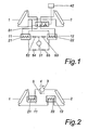
- FIG. 1 schematically shows the basic concept of the present invention.
- a first ambient heat exchanger 1 is designed for example as a solar collector.
- a second ambient heat exchanger 2 is a geothermal collector, wherein it is meaningless for the present invention, whether it is a deep collector, which is arranged in a borehole to a depth of 100 m or more, or a flat collector, in a Depth of about 1 m to 2 m large buried in the ground.
- a first high pressure vessel 11 and a second high pressure vessel 12 are provided which have a first heat exchanger 21 and a second heat exchanger 22, respectively.
- a multi-way valve 51 ensures that the first ambient heat exchanger 1 is optionally connected to the first heat exchanger 21 or the second heat exchanger 22. At the same time, the second ambient heat exchanger 2 is connected to the respective other heat exchanger 22, 21. Not shown circulation pumps provide for the transport of a working fluid in the heat transfer fluid circuits of the first and second ambient heat exchanger 1, 2.
- a control device 42 provides for each optimal switching of the multi-way valve 51. By heating one of the high-pressure vessels 11, 12 through the respective heat exchanger 21, 22, the internal pressure in this high pressure container 11, 12 increases, so that there is a pressure difference to the other high pressure container 12, 11. This pressure difference can be converted by a working machine 31, which is designed for example as a turbine, into mechanical work.
- the multi-way valve 51 is reversed, so that now the other high-pressure vessel 12, 11 is heated and the relaxation by the working machine 31 takes place in the reverse direction.
- the working machine 31 may be reversible, or valves 52, 53, 54, 55 are used to ensure the required guidance of the working medium between the high-pressure vessels 11, 12 and the working machine 31.
- a coolant circuit is arranged so that in succession, the first ambient heat exchanger 1, the first heat exchanger 21, the second ambient heat exchanger 2 and the second heat exchanger 22 are connected in a closed circuit.
- a reversible circulating pump 3 is capable of selectively pumping the working fluid of this circuit in either direction. If the circulation pump 3 is driven in the direction of the arrow 4, the heat from the ambient heat exchanger 2 is used via the first heat exchanger 21 to heat the first high-pressure container 11, after which the working medium flows into the colder ambient heat exchanger 2 and then via the second heat exchanger 22 the second High pressure tank 12 cools.
- the working medium flowing out of the first ambient heat exchanger 1 heats the second high-pressure vessel 12 via the second heat exchanger 22 and then flows through the second ambient heat exchanger 2 and then cools over the first heat exchanger 21, the first high pressure tank 11.
- the rest of the circuit largely corresponds to the Fig. 1 , In this embodiment, it is possible to switch without special valves between heating and cooling of the two high-pressure vessels 11, 12.
- Fig. 1, Fig. 2 only schematically show the basic operation of the present invention. Modifications are possible in many ways. For example, it is possible to provide more than two high-pressure vessels 11, 12 and to bring them into contact with the ambient heat exchangers 1, 2 after a predetermined switching cycle and thereby to heat or cool them. Further modifications of the invention are in Fig. 3 shown.
- the first high-pressure vessel 11 is provided with a first heat exchanger 21 and a fifth heat exchanger 25.
- the second high pressure vessel 12 is equipped with a second heat exchanger 22 and a sixth heat exchanger 26.
- the first ambient heat exchanger 1 can be connected via valves 56, 57 optionally to the first heat exchanger 21 and the second heat exchanger 22.
- the second ambient heat exchanger 2 via valves 58, 59 optionally connectable to the fifth heat exchanger 25 and the sixth heat exchanger 26.
- the working machine 31 is connected via valves 52, 53 to the first high-pressure container 11 and the second high-pressure vessel 12 in conjunction.
- the working machine 31 can be driven by the working fluid from the high-pressure vessel 11, 12 with higher pressure in the other high pressure vessel 12, 11 is released at lower pressure.
- the pressure of the working medium moves in the order of about 200 bar, but can be up to 300 bar and more.
- the first and the second high pressure vessels 11, 12 are connected via high pressure lines with valves 61, 62, 63, 64 with a third high pressure vessel 13 and a fourth high pressure vessel 14 in connection.
- the third high pressure vessel 13 has a third heat exchanger 23 and a seventh heat exchanger 27, while the fourth high pressure vessel 14 has a fourth high pressure vessel 24 and an eighth heat exchanger 28.
- the third, the fourth, the seventh and the eighth heat exchangers 23, 24, 27, 28 are connected via valves 65, 66 to a compressor 32, which is driven by the working machine 31.
- a plurality of high-pressure buffer reservoirs 41 are connected via the valves 61, 62, 63, 64 to the high-pressure vessels 11, 12, 13, 14 and are subsequently coupled to the seventh and eighth heat exchangers 27, 28.
- the high-pressure circuit with the seventh and the eighth heat exchanger 27, 28 with another working machine 33 in connection which communicates at its downstream side via valves 67, 68 with the third and the fourth heat exchanger 23, 24 in connection.
- the high-pressure vessels 11, 12 are filled with a working medium having an equal pressure of, for example, 200 bar.
- the working medium may be air, but it may also be a suitable other gas.
- the temperature in this ambient heat exchanger 1 increases, while the temperature in the ambient heat exchanger 2 is low, since it is located in the shade, within a building or in the ground.
- the valves 56 and 59 are opened and the valves 57 and 58 are closed. Therefore, the first high-pressure tank 11 is heated via the first heat exchanger 21 while the second high-pressure tank 12 is cooled via the sixth heat exchanger 26.
- the increased by the increase in temperature pressure in the first high-pressure vessel 11 is processed via the working machine 31, and it is working medium supplied to the second high-pressure vessel 12.
- the working machine 31 is mechanically coupled to the compressor 32, which compresses the working fluid to high pressure and first through the seventh and / or eighth heat exchanger 27, 28 leads, where the heat of compression to the third and / or fourth high-pressure vessel 13, 14 is discharged.
- working fluid is stored under high pressure.
- the present invention makes it possible to convert heat energy with high efficiency and extremely flexible into mechanical work.
Abstract
Description
Die Erfindung betrifft eine Wärmekraftmaschine gemäß dem Oberbegriff von Patentanspruch 1.The invention relates to a heat engine according to the preamble of
Es ist bekannt, dass sich durch Ausnutzung von natürlich vorkommenden Temperaturdifferenzen mechanische Arbeit gewinnen lässt. So kann beispielsweise die Wärme aus Solaranlagen oder aus Erdwärmetauschern zu diesem Zweck herangezogen werden.It is known that mechanical work can be gained by exploiting naturally occurring temperature differences. For example, the heat from solar systems or geothermal heat exchangers can be used for this purpose.
Aus der
Die
Die
Die
Aufgabe der vorliegenden Erfindung ist es, eine Wärmekraftmaschine der oben beschriebenen Art anzugeben, die diese Nachteile vermeidet und die die zur Verfügung stehenden Temperaturniveaus optimal ausnutzt und einen hohen Wirkungsgrad aufweist. Im weiteren soll ein einfacher konstruktiver Aufbau erreicht werden. Eine weitere Aufgabe der Erfindung ist es, ein Verfahren anzugeben, das hohe Wirkungsgrade und eine große Flexibilität ermöglicht.Object of the present invention is to provide a heat engine of the type described above, which avoids these disadvantages and optimally utilizes the available temperature levels and has a high efficiency. In addition, a simple structural design should be achieved. Another object of the invention is to provide a method which enables high efficiencies and great flexibility.
Erfindungsgemäß werden diese Aufgaben durch die Merkmale von Patentanspruch 1 gelöst. Auf diese Weise ist es möglich, ein Arbeitsmedium auf hohen Druck zu bringen, um dieses zu speichern oder nach Bedarf abzuarbeiten.According to the invention, these objects are achieved by the features of
Wesentlich an der Erfindung ist einerseits, dass ein Arbeitsmedium zur Umsetzung der thermischen Energie eingesetzt wird, das unter hohem Druck steht, um hohe Wirkungsgrade zu erreichen. Andererseits kann jedoch durch die räumliche Trennung der Kollektoren, d.h. der Umgebungswärmetauscher, ein wesentlich schnellerer Arbeitszyklus realisiert werden, da direkt zwischen Erwärmung und Abkühlung umgeschalten werden kann. Ein weiterer Vorteil des erfindungsgemäßen Systems besteht in der Tatsache, dass keine Speisepumpe erforderlich ist, um die Hochdruckbehälter mit dem Arbeitsmedium zu befüllen, da diese im Wesentlichen zwischen den Hochdruckbehältern hin und her strömt. Da die Umgebungswärmetauscher nur mit einem Niederdruckmedium durchströmt sind, können handelsübliche Sonnenkollektoren, Erdwärmetauscher oder dgl. verwendet werden, was den konstruktiven Aufbau vereinfacht und die Kosten senkt.Essential to the invention, on the one hand, that a working medium is used to implement the thermal energy, which is under high pressure in order to achieve high efficiencies. On the other hand, however, due to the spatial separation of the collectors, i. the ambient heat exchanger, a much faster duty cycle can be realized, since it can be switched directly between heating and cooling. Another advantage of the system according to the invention resides in the fact that no feed pump is required to fill the high-pressure containers with the working medium, since this essentially flows back and forth between the high-pressure containers. Since the ambient heat exchanger only flows through a low-pressure medium, commercial solar panels, geothermal heat exchangers or the like. Can be used, which simplifies the structural design and reduces costs.
Ein besonderer Vorteil der vorliegenden Erfindung besteht darin, dass durch die Trennung der Komponenten eine große Flexibilität hinsichtlich der Ausnutzung der aktuell zur Verfügung stehenden Temperaturniveaus möglich ist.A particular advantage of the present invention is that by the separation of the components a great flexibility in terms of the utilization of the currently available temperature levels is possible.
Eine konstruktiv besonders günstige Lösung der Erfindung ist gegeben, wenn die Arbeitsmaschine als Turbine ausgebildet ist. Die Arbeitsmaschine kann umsteuerbar, d.h. in beide Richtungen betreibbar ausgeführt sein, wodurch sich der schaltungstechnische Aufwand verringert.A structurally particularly favorable solution of the invention is given if the working machine is designed as a turbine. The working machine can be reversible, that is to say that they can be operated in both directions, which reduces the circuitry complexity.
Eine Steigerung des Wirkungsgrads kann dadurch erreicht werden, dass der erste Hochdruckbehälter neben dem ersten Wärmetauscher einen fünften Wärmetauscher aufweist, und dass der zweite Hochdruckbehälter neben dem zweiten Wärmetauscher einen sechsten Wärmetauscher aufweist. Insbesondere vorteilhaft ist es in diesem Zusammenhang, wenn der erste Umgebungswärmetauscher wahlweise mit dem fünften und dem sechsten Wärmetauscher verbindbar ist und dass der zweite Umgebungswärmetauscher wahlweise mit dem ersten und dem zweiten Wärmetauscher verbindbar ist. Die Schaltung wird dabei bevorzugterweise so ausgeführt, dass der erste Umgebungswärmetauscher mit dem fünften und dem sechsten Wärmetauscher in einem geschlossenen Wärmeträgerkreislauf angeordnet ist und dass der zweite Umgebungswärmetauscher mit dem ersten und dem zweiten Wärmetauscher in einem weiteren geschlossenen Wärmeträgerkreislauf angeordnet ist. Der erste und der zweite Wärmetauscher dienen dabei im Normalbetrieb dazu, abwechselnd dem ersten und dem zweiten Hochdruckbehälter Wärme zuzuführen, während dem anderen der beiden Hochdruckbehälter über den fünften bzw. sechsten Wärmetauscher Wärme entzogen wird. Es ist jedoch festzuhalten, dass unter besonderen Betriebsbedingungen, beispielsweise in der Nacht, über einen Umgebungswärmetauscher, der normalerweise zur Aufnahme von Wärme dient, wie etwa einen Solarkollektor, Wärme abgegeben werden kann, während über einen anderen Umgebungswärmetauscher, der beispielsweise als Erdwärmetauscher ausgebildet ist, Wärme aufgenommen wird. Durch die besondere Flexibilität der erfindungsgemäßen Vorrichtung können auch solche ungewöhnlichen Umweltbedingungen ausgenützt werden, um Wärme in mechanische Arbeit umzuwandeln. Es ist insbesondere auch möglich, einen Umgebungswärmetauscher zur Beheizung oder Kühlung von Gebäuden oder Anlagen zu verwenden.An increase in the efficiency can be achieved in that the first high-pressure vessel has a fifth heat exchanger in addition to the first heat exchanger, and that the second high-pressure vessel in addition to the second heat exchanger has a sixth heat exchanger. In this connection, it is particularly advantageous if the first ambient heat exchanger can be optionally connected to the fifth and the sixth heat exchanger, and that the second ambient heat exchanger can optionally be connected to the first and the second heat exchanger. The circuit is thereby preferably designed so that the first ambient heat exchanger is arranged with the fifth and the sixth heat exchanger in a closed heat transfer circuit and that the second ambient heat exchanger is arranged with the first and the second heat exchanger in a further closed heat transfer circuit. In normal operation, the first and the second heat exchangers serve to supply heat alternately to the first and the second high-pressure vessels, while heat is withdrawn from the other of the two high-pressure vessels via the fifth or sixth heat exchanger. It should be noted, however, that under particular operating conditions, for example at night, heat may be dissipated via an ambient heat exchanger, which normally serves to absorb heat, such as a solar collector, while another ambient heat exchanger is designed, for example, as a geothermal heat exchanger. Heat is absorbed. Due to the particular flexibility of the device according to the invention, even such unusual environmental conditions can be exploited to convert heat into mechanical work. In particular, it is also possible to use an ambient heat exchanger for heating or cooling buildings or installations.
Die Flexibilität im Einsatz kann dadurch gesteigert werden, dass im weiteren ein dritter Hochdruckbehälter und ein vierter Hochdruckbehälter vorgesehen sind, die wahlweise mit der Arbeitsmaschine verbindbar sind. Die Wärmezufuhr und Wärmeabfuhr erfolgt dabei in bevorzugter Weise dadurch, der dritte Hochdruckbehälter einen dritten Wärmetauscher aufweist und dass der vierte Hochdruckbehälter einen vierten Wärmetauscher aufweist.The flexibility in use can be increased by further providing a third high-pressure vessel and a fourth high-pressure vessel, which can be optionally connected to the working machine. The heat supply and heat dissipation takes place in a preferred manner thereby, the third high pressure vessel having a third heat exchanger and that the fourth high pressure vessel has a fourth heat exchanger.
Eine besonders begünstigte Ausführungsvariante der vorliegenden Erfindung sieht vor, dass der dritte Wärmetauscher und der vierte Wärmetauscher wahlweise mit dem Verdichter verbindbar sind. Zusätzlich können der dritte Wärmetauscher und der vierte Wärmetauscher wahlweise mit einer weiteren Arbeitsmaschine verbindbar sein.A particularly favored embodiment variant of the present invention provides that the third heat exchanger and the fourth heat exchanger can optionally be connected to the compressor. In addition, the third heat exchanger and the fourth heat exchanger may optionally be connectable to another work machine.
Eine weitere Ausbaustufe der Erfindung sieht vor, dass der dritte Hochdruckbehälter neben dem dritten Wärmetauscher einen siebenten Wärmetauscher aufweist, und dass der vierte Hochdruckbehälter neben dem vierten Wärmetauscher einen achten Wärmetauscher aufweist, wobei insbesondere der siebente Wärmetauscher und der achte Wärmetauscher in einem Hochdruckwärmeträgerkreislauf mit dem Verdichter und mit einer Arbeitsmaschine verbindbar sind. Auf diese Weise wird eine bisher unerreichte Variabilität im Hinblick auf die Ausnutzung verschiedenster Umgebungsbedingungen erzielt. Kurzfristige Perioden, in denen die Energienachfrage das Angebot übersteigt können bevorzugterweise dadurch überbrückt werden, dass zusätzlich Hochdruckpufferspeicher vorgesehen sind.A further expansion stage of the invention provides that the third high-pressure vessel in addition to the third heat exchanger has a seventh heat exchanger, and that the fourth high-pressure vessel next to the fourth heat exchanger has an eighth heat exchanger, in particular the seventh heat exchanger and the eighth heat exchanger in a high-pressure heat carrier circuit with the compressor and are connectable to a work machine. In this way, a previously unattained variability in terms of exploiting various environmental conditions is achieved. Short-term periods in which the energy demand exceeds the supply can be preferably bridged by the fact that additional high-pressure buffer storage are provided.
Weiters betrifft die vorliegende Erfindung ein Verfahren zur Umwandlung thermischer Energie in mechanische Arbeit, bei dem durch einen ersten Umgebungswärmetauscher Wärme auf einem ersten Temperaturniveau von der Umgebung aufgenommen wird und an ein unter Hochdruck stehendes Arbeitsmedium abgegeben wird, das in einem Hochdruckbehälter vorliegt, und bei dem ein zweiter Umgebungswärmetauscher Wärme auf einem zweiten Temperaturniveau mit der Umgebung austauscht, wobei das unter Hochdruck stehende Arbeitsmedium in einer Arbeitsmaschine entspannt wird.Furthermore, the present invention relates to a method for converting thermal energy into mechanical work, in which heat is taken up by a first ambient heat exchanger at a first temperature level from the environment and delivered to a high-pressure working medium, which is present in a high-pressure vessel, and in which a second ambient heat exchanger exchanges heat at a second temperature level with the environment, wherein the high pressure working medium is relaxed in a work machine.
Erfindungsgemäß ist dieses Verfahren dadurch gekennzeichnet, dass ein erster Hochdruckbehälter abwechselnd thermisch mit dem ersten Umgebungswärmetauscher und mit dem zweiten Umgebungswärmetauscher in Verbindung gebracht wird. Durch kurze Zykluszeiten können hohe Wirkungsrade erreicht werden.According to the invention, this method is characterized in that a first high-pressure container is alternately brought into thermal communication with the first ambient heat exchanger and with the second ambient heat exchanger. Short cycle times allow high levels of efficiency to be achieved.
Eine begünstigte Variante des erfindungsgemäßen Verfahrens sieht vor, dass ein zweiter Hochdruckbehälter abwechselnd thermisch mit dem ersten Umgebungswärmetauscher und mit dem zweiten Umgebungswärmetauscher in Verbindung gebracht wird, so dass jeweils der erste Hochdruckbehälter mit einem Umgebungswärmetauscher und der zweite Hochdruckbehälter mit dem anderen Umgebungswärmetauscher thermisch in Verbindung steht.A favored variant of the method according to the invention provides that a second high pressure vessel is alternately thermally associated with the first ambient heat exchanger and the second ambient heat exchanger, so that each of the first high-pressure vessel with an ambient heat exchanger and the second high-pressure vessel with the other ambient heat exchanger is thermally in communication ,
Das Verfahren wird dabei insbesondere so geführt, dass abwechselnd in einem ersten Arbeitstakt das Arbeitsmedium in dem ersten Hochdruckbehälter über einen ersten Wärmetauscher erwärmt wird, indem der erste Wärmetauscher mit dem ersten Umgebungswärmetauscher in Verbindung gebracht wird, während gleichzeitig der zweite Hochdruckbehälter über einen sechsten Wärmetauscher gekühlt wird, indem der sechste Wärmetauscher mit dem zweiten Umgebungswärmetauscher in Verbindung gebracht wird, und in einem zweiten Arbeitstakt das Arbeitsmedium in dem zweiten Hochdruckbehälter über einen zweiten Wärmetauscher erwärmt wird, indem der zweite Wärmetauscher mit dem ersten Umgebungswärmetauscher in Verbindung gebracht wird, während gleichzeitig der erste Hochdruckbehälter über einen fünften Wärmetauscher gekühlt wird, indem der fünfte Wärmetauscher mit dem zweiten Umgebungswärmetauscher in Verbindung gebracht wird.The method is in particular carried out so that alternately in a first cycle, the working medium is heated in the first high-pressure vessel via a first heat exchanger by the first heat exchanger is brought into communication with the first ambient heat exchanger while simultaneously cooled the second high-pressure vessel via a sixth heat exchanger is brought by the sixth heat exchanger in communication with the second ambient heat exchanger, and in a second power stroke, the working fluid in the second high-pressure vessel via a second heat exchanger is heated by the second heat exchanger is brought into communication with the first ambient heat exchanger, while at the same time the first high pressure vessel is cooled via a fifth heat exchanger by the fifth heat exchanger is brought into communication with the second ambient heat exchanger.
In der Folge wird die Erfindung anhand der in den Figuren dargestellten Ausführungsvarianten näher erläutert. Es zeigen:
- Fig. 1
- ein schematisches Schaltungsdiagramm, das das Grundkonzept der Erfindung erklärt;
- Fig. 2
- eine Variante der Schaltung von
Fig. 1 ; und - Fig. 3
- eine bevorzugte Ausführungsform der Erfindung in einem Schaltungsdiagramm.
- Fig. 1
- a schematic circuit diagram that explains the basic concept of the invention;
- Fig. 2
- a variant of the circuit of
Fig. 1 ; and - Fig. 3
- a preferred embodiment of the invention in a circuit diagram.
Bei der Ausführungsvariante von
Es wird hiermit festgehalten, dass
Bei der Ausführungsvariante von
Der erste und der zweite Hochdruckbehälter 11, 12 stehen über Hochdruckleitungen mit Ventilen 61, 62, 63, 64 mit einem dritten Hochdruckbehälter 13 und einem vierten Hochdruckbehälter 14 in Verbindung. Der dritte Hochdruckbehälter 13 besitzt dabei einen dritten Wärmetauscher 23 und einen siebenten Wärmetauscher 27, während der vierte Hochdruckbehälter 14 einen vierten Hochdruckbehälter 24 und einen achten Wärmetauscher 28 aufweist. Der dritte, der vierte, der siebente und der achte Wärmetauscher 23, 24, 27, 28 stehen über Ventile 65, 66 mit einem Verdichter 32 in Verbindung, der von der Arbeitsmaschine 31 angetrieben wird.The first and the second
Mehrere Hochdruckpufferspeicher 41 stehen über die Ventile 61, 62, 63, 64 mit den Hochdruckbehältern 11, 12, 13, 14 in Verbindung und sind im Weiteren mit dem siebenten und dem achten Wärmetauscher 27, 28 gekoppelt. Daneben ist der Hochdruckkreislauf mit dem siebenten und dem achten Wärmetauscher 27, 28 mit einer weiteren Arbeitsmaschine 33 in Verbindung, die an ihrer stromabwärtigen Seite über Ventile 67, 68 mit dem dritten und dem vierten Wärmetauscher 23, 24 in Verbindung steht.A plurality of high-
In der Folge wird die Arbeitsweise der erfindungsgemäßem Vorrichtung erläutert.In the following, the operation of the device according to the invention will be explained.
Anfänglich sind die Hochdruckbehälter 11, 12 mit einem Arbeitsmedium mit einem gleichen Druck von beispielsweise 200 bar gefüllt. Das Arbeitsmedium kann Luft sein, es kann sich aber auch um ein passendes anderes Gas handeln. Es wird nun angenommen, dass durch Sonneneinstrahlung auf den ersten Umgebungswärmetauscher 1 oder durch sonstige Erwärmung die Temperatur in diesem Umgebungswärmetauscher 1 ansteigt, während die Temperatur im Umgebungswärmetauscher 2 gering ist, da dieser im Schatten, innerhalb eines Gebäudes oder im Erdreich angeordnet ist. In einem ersten Arbeitszyklus sind die Ventile 56 und 59 geöffnet und die Ventile 57 und 58 geschlossen. Daher wird der erste Hochdruckbehälter 11 über den ersten Wärmetauscher 21 erwärmt, während der zweite Hochdruckbehälter 12 über den sechsten Wärmetauscher 26 gekühlt wird. Der durch die Temperaturerhöhung angestiegene Druck im ersten Hochdruckbehälter 11 wird über die Arbeitsmaschine 31 abgearbeitet, und es wird Arbeitsmedium dem zweiten Hochdruckbehälter 12 zugeführt. Die Arbeitsmaschine 31 ist mechanisch mit dem Verdichter 32 gekoppelt, der das Arbeitsmedium auf Hochdruck verdichtet und zunächst durch den siebenten und/oder achten Wärmetauscher 27, 28 führt, wo die Kompressionswärme an den dritten und/oder vierten Hochdruckbehälter 13, 14 abgegeben wird. In den Hochdruckpufferspeichern 41 wird Arbeitsmedium unter hohem Druck gespeichert.Initially, the high-
Der Wechsel zwischen der Erwärmung des ersten und des zweiten Hochdruckbehälters 11, 12 ist oben bereits ausführlich beschrieben worden. Nach mehreren Zyklen ist die Temperatur und damit der Druck in dem dritten und/oder dem vierten Hochdruckbehälter 13, 14 so weit angestiegen, dass das Arbeitsmedium über die weitere Arbeitsmaschine 33 entspannt und abgearbeitet werden kann. Das entspannte und kühle Arbeitsmedium wird durch den dritten und/oder den vierten Wärmetauscher 23, 24 durchgeleitet und kühlt den betreffenden Hochdruckbehälter 13, 14 ab. Bei entsprechender Steuerung kann dabei Kälte erzeugt werden, die zur Kühlung von Gebäuden oder Anlagen verwendet werden kann.The change between the heating of the first and second high-
Die vorliegende Erfindung ermöglicht es, Wärmeenergie mit hohem Wirkungsgrad und äußerst flexibel in mechanische Arbeit umzuwandeln.The present invention makes it possible to convert heat energy with high efficiency and extremely flexible into mechanical work.
Claims (32)
- A heat engine with a first ambient heat exchanger (1) for exchanging heat with the ambient environment at a first temperature level, a second ambient heat exchanger (2) for exchanging heat with the ambient environment at a second temperature level, a first high-pressure tank (11) for receiving a working medium under high pressure, a second high-pressure tank (12) for receiving a working medium under a high pressure, a working machine (31) for gaining mechanical work from the expansion of the working medium from a high-pressure tank (11, 12), and with a control device (42) for controlling the process, characterized in that the first high-pressure tank (11) comprises a first heat exchanger (21) which is spatially separated from the ambient heat exchangers (1, 2) and can be connected with the first ambient heat exchanger (1), and that the second high-pressure tank (12) comprises a second heat exchanger (22) which is spatially separated from the ambient heat exchangers (1, 2) and can be connected with the second heat exchanger (2), and that a compressor (32) is provided which is mechanically coupled with the working machine (31).
- A heat engine according to claim 1, characterized in that the working machine (31) is arranged as a turbine.
- A heat engine according to claim 1 or 2, characterized in that the compressor (32) is arranged as a high-pressure compressor.
- A heat engine according to one of the claims 1 to 3, characterized in that the first ambient heat exchanger (1) is connected in a closed heat carrier cycle with the first heat exchanger (21) and/or the second heat exchanger (22).
- A heat engine according to one of the claims 1 to 4, characterized in that the second ambient heat exchanger (2) is connected in a closed heat carrier cycle with the first heat exchanger (21) and/or the second heat exchanger (22).
- A heat engine according to one of the claims 1 to 5, characterized in that the working machine (31) is reversible.
- A heat engine according to one of the claims 1 to 6, characterized in that the first high-pressure tank (11) comprises a fifth heat exchanger (25) in addition to the first heat exchanger (21), and that the second high-pressure tank (12) comprises a sixth heat exchanger (26) in addition to the second heat exchanger (22).
- A heat engine according to claim 7, characterized in that the first ambient heat exchanger (1) is optionally connectable with the fifth and sixth heat exchanger (25, 26) and that the second ambient heat exchanger (2) is optionally connectable with the first and second heat exchanger (21, 22).
- A heat engine according to claim 8, characterized in that the first ambient heat exchanger (1) with the fifth and sixth heat exchanger (25, 26) is arranged in a closed heat carrier cycle and that the second ambient heat exchanger (2) with the first and second heat exchanger (21, 22) is arranged in a further closed heat carrier cycle.
- A heat engine according to one of the claims 1 to 9, characterized in that the first ambient heat exchanger (1) or the second ambient heat exchanger (2) is arranged as a solar collector.
- A heat engine according to one of the claims 1 to 10, characterized in that the first ambient heat exchanger (1) or the second ambient heat exchanger (2) is arranged as an earth-to-air exchanger.
- A heat engine according to one of the claims 1 to 11, characterized in that the first ambient heat exchanger (1) or the second ambient heat exchanger (2) is arranged as a heat exchanger for heating and/or cooling rooms or installations.
- A heat engine according to one of the claims 1 to 12, characterized in that a third high-pressure tank (13) and a fourth high-pressure tank (14) are further provided which are optionally connectable with the working machine (31).
- A heat engine according to claim 13, characterized in that the third and/or fourth high-pressure tank (13, 14) are insulated against the ambient environment.
- A heat engine according to claim 13 or 14, characterized in that the third high-pressure tank (13) comprises a third heat exchanger (23) and that the fourth high-pressure tank (14) comprises a fourth heat exchanger (24).
- A heat engine according to claim 15, characterized in that the third heat exchanger (23) and the fourth heat exchanger (24) are optionally connectable with the compressor (32).
- A heat engine according to claim 15 or 16, characterized in that the third heat exchanger (23) and the fourth heat exchanger (24) are optionally connectable with a further working machine (33).
- A heat engine according to one of the claims 13 to 17, characterized in that the third high-pressure tank (13) comprises a seventh heat exchanger (27) in addition to the third heat exchanger (23) and that the fourth high-pressure tank (14) comprises an eighth heat exchanger (28) in addition to the fourth heat exchanger (24).
- A heat engine according to claim 18, characterized in that the seventh heat exchanger (27) and the eighth heat exchanger (28) are connectable in a high-pressure heat carrier cycle with the compressor (32) and with a working machine (31, 33).
- A heat engine according to one of the claims 1 to 19, characterized in that high-pressure buffer storage units (41) are additionally provided.
- A method for converting thermal energy into mechanical work in which heat is absorbed from the ambient environment at a first temperature level by a first ambient heat exchanger (1) and is conveyed to a working medium under high pressure present in a high-pressure tank (11, 12), and in which a second ambient heat exchanger (2) exchanges heat at a second temperature level with the ambient environment, with the working medium under high pressure being expanded in a working machine (31), characterized in that a first high-pressure tank (11) is brought into thermal connection in an alternating manner with the first ambient heat exchanger (1) and the second ambient heat exchanger (2), and that a compressor (32) is driven by the working machine (31) which compresses the working medium or a further working medium.
- A method according to claim 21, characterized in that a second high-pressure tank (12) is brought into connection thermally in an alternating manner with the first ambient heat exchanger (1) and with the second ambient heat exchanger (2), so that the first high-pressure tank (11) is thermally in connection with an ambient heat exchanger (1, 2) and the second high-pressure tank (12) is thermally in connection with the other ambient heat exchanger (2, 1).
- A method according to claim 21 or 22, characterized in that the working medium in the first high-pressure tank (11) is heated and cooled via a first heat exchanger (21), such that the first heat exchanger (21) is brought into connection in an alternating manner with the first ambient heat exchanger (1) and with the second ambient heat exchanger (2).
- A method according to one of the claims 21 to 23, characterized in that the working medium is heated and cooled in the first high-pressure tank (11) via a first heat exchanger (21), such that the first heat exchanger (21) is brought into connection in an alternating manner with the first ambient heat exchanger (1) and with the second ambient heat exchanger (2).
- A method according to one of the claims 21 to 24, characterized in that in a first working cycle the working medium is heated in the first high-pressure tank (11) via a first heat exchanger (21) in an alternating manner, such that the first heat exchanger (21) is brought into connection with the first ambient heat exchanger (1), whereas simultaneously the second high-pressure tank (12) is cooled via a sixth heat exchanger (26), such that the sixth heat exchanger (26) is brought into connection with the second ambient heat exchanger (2), and in a second work cycle the working medium in the second high-pressure tank (12) is heated via a second heat exchanger (22), such that the second heat exchanger (22) is brought into connection with the first ambient heat exchanger (1), whereas simultaneously the first high-pressure tank (11) is cooled via a fifth heat exchanger (25), such that the fifth heat exchanger (25) is brought into connection with the second ambient heat exchanger (2).
- A method according to one of the claims 1 to 25, characterized in that the compressor (32) heats a working medium which conveys the heat in an alternating manner via a third and a fourth heat exchanger (23, 24) to a working medium which is present in a third or fourth high-pressure tank (13, 14).
- A method according to one of the claims 21 to 26, characterized in that the working medium from the first and second high-pressure tank (11, 12) and optionally from the third and fourth high-pressure tank (13, 14) is expanded in a further working machine.
- A method according to one of the claims 21 to 27, characterized in that the working medium under high pressure is stored in further high-pressure buffer storage units (41).
- A method according to claim 28, characterized in that compressed air is used as a working medium, which is used for driving further working machines such as pumps, generators, motor vehicles or the like.
- A method according to one of the claims 21 to 29, characterized in that the alternating delivery of the heat exchangers (21, 22) is performed by reversing a conveyor pump (3).
- A method according to one of the claims 21 to 30, characterized in that the heat produced during the compression is used for heating buildings or installations.
- A method according to one of the claims 21 to 31, characterized in that the refrigeration produced during the expansion is used for cooling buildings or installations.
Applications Claiming Priority (2)
| Application Number | Priority Date | Filing Date | Title |
|---|---|---|---|
| AT0099504A AT414268B (en) | 2004-06-08 | 2004-06-08 | HEAT ENGINE |
| PCT/AT2005/000194 WO2005121551A1 (en) | 2004-06-08 | 2005-06-06 | Heat engine |
Publications (2)
| Publication Number | Publication Date |
|---|---|
| EP1759116A1 EP1759116A1 (en) | 2007-03-07 |
| EP1759116B1 true EP1759116B1 (en) | 2008-02-13 |
Family
ID=34981453
Family Applications (1)
| Application Number | Title | Priority Date | Filing Date |
|---|---|---|---|
| EP05747198A Not-in-force EP1759116B1 (en) | 2004-06-08 | 2005-06-06 | Heat engine |
Country Status (14)
| Country | Link |
|---|---|
| US (1) | US20070240418A1 (en) |
| EP (1) | EP1759116B1 (en) |
| JP (1) | JP2008501885A (en) |
| KR (1) | KR20070043772A (en) |
| CN (1) | CN101010507A (en) |
| AT (2) | AT414268B (en) |
| AU (1) | AU2005252257A1 (en) |
| BR (1) | BRPI0511895A (en) |
| CA (1) | CA2569696A1 (en) |
| DE (1) | DE502005002841D1 (en) |
| MX (1) | MXPA06014278A (en) |
| RU (1) | RU2006147231A (en) |
| WO (1) | WO2005121551A1 (en) |
| ZA (1) | ZA200610262B (en) |
Families Citing this family (8)
| Publication number | Priority date | Publication date | Assignee | Title |
|---|---|---|---|---|
| SE533122C2 (en) * | 2008-03-12 | 2010-06-29 | Oerjan Forslund | Converters of solar energy to electricity |
| CN101302945B (en) * | 2008-07-10 | 2011-04-27 | 张中和 | Equipment for generating energy by fluid temperature difference |
| EP2159496A1 (en) * | 2008-08-29 | 2010-03-03 | Vito NV | Controller for energy supply systems |
| JP5593520B2 (en) * | 2010-02-09 | 2014-09-24 | ジボ ナタージー ケミカル インダストリー カンパニー リミテッド | Temperature difference engine device |
| AT511637B1 (en) * | 2011-06-20 | 2013-08-15 | Innova Gebaeudetechnik Gmbh | TECHNICAL SYSTEM FOR GAS COMPRESSION USING TEMPERATURE AND PRINTING DIFFERENCES |
| GB2497088A (en) * | 2011-11-29 | 2013-06-05 | Andrzej Plucinski | Electricity generator powered by environmental heat sources |
| CN104061029B (en) * | 2014-05-16 | 2015-12-30 | 张中和 | A kind of solar energy heating fluid temperature difference supercharging air power generating equipment |
| KR101887141B1 (en) * | 2017-12-18 | 2018-08-09 | 한국건설기술연구원 | Power Generating Method and Apparatus using Moving of Materials in Extreme Atmosphere |
Family Cites Families (11)
| Publication number | Priority date | Publication date | Assignee | Title |
|---|---|---|---|---|
| US4584842A (en) * | 1976-08-02 | 1986-04-29 | Tchernev Dimiter I | Solar refrigeration |
| US4202178A (en) * | 1978-06-23 | 1980-05-13 | Peterman Paul L | Low-boiling liquid apparatus |
| FR2501302A1 (en) * | 1981-03-06 | 1982-09-10 | Anvar | Solar powered pump unit with electric working fluid distributor valve - uses bidirectional solenoid valves to couple working fluid between evaporator and motor unit and motor unit and condenser |
| US4993483A (en) * | 1990-01-22 | 1991-02-19 | Charles Harris | Geothermal heat transfer system |
| US5259363A (en) * | 1991-12-23 | 1993-11-09 | Lolar Logistics, Inc. | Solar roofing system |
| DE19713345A1 (en) * | 1997-03-29 | 1998-10-01 | Reschberger Stefan | Solar powered electrical energy generation device |
| JPH11294316A (en) * | 1998-04-08 | 1999-10-26 | Naohisa Sawada | Method of generating power by utilizing solar heat |
| AT410966B (en) * | 2001-03-16 | 2003-09-25 | Bammer Peter | DEVICE FOR COMPRESSING A GAS BY MEANS OF SOLAR ENERGY AND / OR AMBIENT HEAT |
| US6981377B2 (en) * | 2002-02-25 | 2006-01-03 | Outfitter Energy Inc | System and method for generation of electricity and power from waste heat and solar sources |
| US6615601B1 (en) * | 2002-08-02 | 2003-09-09 | B. Ryland Wiggs | Sealed well direct expansion heating and cooling system |
| US7234314B1 (en) * | 2003-01-14 | 2007-06-26 | Earth To Air Systems, Llc | Geothermal heating and cooling system with solar heating |
-
2004
- 2004-06-08 AT AT0099504A patent/AT414268B/en not_active IP Right Cessation
-
2005
- 2005-06-06 MX MXPA06014278A patent/MXPA06014278A/en not_active Application Discontinuation
- 2005-06-06 US US11/628,979 patent/US20070240418A1/en not_active Abandoned
- 2005-06-06 KR KR1020077000233A patent/KR20070043772A/en not_active Application Discontinuation
- 2005-06-06 DE DE502005002841T patent/DE502005002841D1/en not_active Expired - Fee Related
- 2005-06-06 WO PCT/AT2005/000194 patent/WO2005121551A1/en active IP Right Grant
- 2005-06-06 JP JP2007526100A patent/JP2008501885A/en active Pending
- 2005-06-06 BR BRPI0511895-6A patent/BRPI0511895A/en not_active IP Right Cessation
- 2005-06-06 AT AT05747198T patent/ATE386210T1/en not_active IP Right Cessation
- 2005-06-06 CN CNA2005800187055A patent/CN101010507A/en active Pending
- 2005-06-06 CA CA002569696A patent/CA2569696A1/en not_active Abandoned
- 2005-06-06 AU AU2005252257A patent/AU2005252257A1/en not_active Abandoned
- 2005-06-06 EP EP05747198A patent/EP1759116B1/en not_active Not-in-force
- 2005-06-06 RU RU2006147231/06A patent/RU2006147231A/en not_active Application Discontinuation
-
2006
- 2006-12-08 ZA ZA200610262A patent/ZA200610262B/en unknown
Also Published As
| Publication number | Publication date |
|---|---|
| ATE386210T1 (en) | 2008-03-15 |
| RU2006147231A (en) | 2008-07-20 |
| KR20070043772A (en) | 2007-04-25 |
| AT414268B (en) | 2006-10-15 |
| JP2008501885A (en) | 2008-01-24 |
| CN101010507A (en) | 2007-08-01 |
| AU2005252257A1 (en) | 2005-12-22 |
| ATA9952004A (en) | 2006-01-15 |
| WO2005121551A1 (en) | 2005-12-22 |
| MXPA06014278A (en) | 2007-05-08 |
| DE502005002841D1 (en) | 2008-03-27 |
| CA2569696A1 (en) | 2005-12-22 |
| EP1759116A1 (en) | 2007-03-07 |
| ZA200610262B (en) | 2008-05-28 |
| BRPI0511895A (en) | 2008-03-25 |
| US20070240418A1 (en) | 2007-10-18 |
Similar Documents
| Publication | Publication Date | Title |
|---|---|---|
| EP1759116B1 (en) | Heat engine | |
| AT502402B1 (en) | METHOD FOR CONVERTING THERMAL ENERGY TO MECHANICAL WORK | |
| EP2574739A1 (en) | Assembly for storing thermal energy and method for its operation | |
| EP3362739A1 (en) | Generation of process steam by means of a high-temperature heat pump | |
| WO2014026863A2 (en) | Method for charging and discharging a heat accumulator and system for storing and releasing thermal energy suitable for said method | |
| EP1310644A1 (en) | Method for recovering the energy of gas expansion and a recovery device for carrying out said method | |
| EP2825735A1 (en) | System for storing and outputting thermal energy and method for operating said system | |
| WO2010043469A1 (en) | Method and device for operating a stirling cycle process | |
| DE202005003611U1 (en) | Thermal electric station for producing and storing electrical energy comprises a compressed air storage unit with heat exchangers for thermally coupling the station and the compressed air storage unit | |
| EP2622289A1 (en) | Heat pump | |
| DE102019127431A1 (en) | Thermal power storage with fixed bed heat storage and fixed bed cold storage and method for operating a thermal power storage | |
| WO2013156284A1 (en) | System for storing and outputting thermal energy having a heat accumulator and a cold accumulator and method for the operation thereof | |
| EP1377751A1 (en) | Device for compressing a gas by using solar energy and/or ambient heat | |
| DE102007027725A1 (en) | Method for producing useful heating and cooling energy, involves absorbing ambient air with turbo-heat pump, where compressed and warmed up air is produced in compression impeller of heat pump | |
| EP1980804A2 (en) | Method for generating thermal energy | |
| EP2859196B1 (en) | Energy transformation system | |
| WO2018029371A1 (en) | Heat exchanger for use in a heating part of a liquid-air energy storage power plant, heating part, and method for operating such a heat exchanger in such a heating part | |
| WO2018114468A1 (en) | Method and apparatus for generating process cold and process steam | |
| EP3208512B1 (en) | Method for regasification of deep-frozen liquefied gas | |
| DE102004008093B4 (en) | Operating process for compressed gas engine involves using heat pump unit to circulate fluid for heating and transfer of heat to compressed gas | |
| WO2018127731A1 (en) | Supply container | |
| DE102009030146A1 (en) | Energy storage has a compressor to give compressed air for conversion into mechanical energy to drive an electricity generator | |
| DE2602651C2 (en) | Electric night storage heating | |
| DE4329585A1 (en) | Gas turbine heating/refrigerating unit-type power station | |
| WO2024046598A1 (en) | System for compressing, storing and providing gas and corresponding method |
Legal Events
| Date | Code | Title | Description |
|---|---|---|---|
| PUAI | Public reference made under article 153(3) epc to a published international application that has entered the european phase |
Free format text: ORIGINAL CODE: 0009012 |
|
| 17P | Request for examination filed |
Effective date: 20061228 |
|
| AK | Designated contracting states |
Kind code of ref document: A1 Designated state(s): AT BE BG CH CY CZ DE DK EE ES FI FR GB GR HU IE IS IT LI LT LU MC NL PL PT RO SE SI SK TR |
|
| DAX | Request for extension of the european patent (deleted) | ||
| GRAP | Despatch of communication of intention to grant a patent |
Free format text: ORIGINAL CODE: EPIDOSNIGR1 |
|
| GRAS | Grant fee paid |
Free format text: ORIGINAL CODE: EPIDOSNIGR3 |
|
| GRAA | (expected) grant |
Free format text: ORIGINAL CODE: 0009210 |
|
| AK | Designated contracting states |
Kind code of ref document: B1 Designated state(s): AT BE BG CH CY CZ DE DK EE ES FI FR GB GR HU IE IS IT LI LT LU MC NL PL PT RO SE SI SK TR |
|
| REG | Reference to a national code |
Ref country code: GB Ref legal event code: FG4D Free format text: NOT ENGLISH |
|
| REG | Reference to a national code |
Ref country code: CH Ref legal event code: EP |
|
| REG | Reference to a national code |
Ref country code: IE Ref legal event code: FG4D Free format text: LANGUAGE OF EP DOCUMENT: GERMAN |
|
| REF | Corresponds to: |
Ref document number: 502005002841 Country of ref document: DE Date of ref document: 20080327 Kind code of ref document: P |
|
| PG25 | Lapsed in a contracting state [announced via postgrant information from national office to epo] |
Ref country code: IS Free format text: LAPSE BECAUSE OF FAILURE TO SUBMIT A TRANSLATION OF THE DESCRIPTION OR TO PAY THE FEE WITHIN THE PRESCRIBED TIME-LIMIT Effective date: 20080613 Ref country code: FI Free format text: LAPSE BECAUSE OF FAILURE TO SUBMIT A TRANSLATION OF THE DESCRIPTION OR TO PAY THE FEE WITHIN THE PRESCRIBED TIME-LIMIT Effective date: 20080213 Ref country code: ES Free format text: LAPSE BECAUSE OF FAILURE TO SUBMIT A TRANSLATION OF THE DESCRIPTION OR TO PAY THE FEE WITHIN THE PRESCRIBED TIME-LIMIT Effective date: 20080524 |
|
| NLV1 | Nl: lapsed or annulled due to failure to fulfill the requirements of art. 29p and 29m of the patents act | ||
| PG25 | Lapsed in a contracting state [announced via postgrant information from national office to epo] |
Ref country code: PL Free format text: LAPSE BECAUSE OF FAILURE TO SUBMIT A TRANSLATION OF THE DESCRIPTION OR TO PAY THE FEE WITHIN THE PRESCRIBED TIME-LIMIT Effective date: 20080213 Ref country code: SI Free format text: LAPSE BECAUSE OF FAILURE TO SUBMIT A TRANSLATION OF THE DESCRIPTION OR TO PAY THE FEE WITHIN THE PRESCRIBED TIME-LIMIT Effective date: 20080213 |
|
| REG | Reference to a national code |
Ref country code: IE Ref legal event code: FD4D |
|
| PG25 | Lapsed in a contracting state [announced via postgrant information from national office to epo] |
Ref country code: SK Free format text: LAPSE BECAUSE OF FAILURE TO SUBMIT A TRANSLATION OF THE DESCRIPTION OR TO PAY THE FEE WITHIN THE PRESCRIBED TIME-LIMIT Effective date: 20080213 Ref country code: SE Free format text: LAPSE BECAUSE OF FAILURE TO SUBMIT A TRANSLATION OF THE DESCRIPTION OR TO PAY THE FEE WITHIN THE PRESCRIBED TIME-LIMIT Effective date: 20080513 Ref country code: PT Free format text: LAPSE BECAUSE OF FAILURE TO SUBMIT A TRANSLATION OF THE DESCRIPTION OR TO PAY THE FEE WITHIN THE PRESCRIBED TIME-LIMIT Effective date: 20080714 Ref country code: NL Free format text: LAPSE BECAUSE OF FAILURE TO SUBMIT A TRANSLATION OF THE DESCRIPTION OR TO PAY THE FEE WITHIN THE PRESCRIBED TIME-LIMIT Effective date: 20080213 Ref country code: DK Free format text: LAPSE BECAUSE OF FAILURE TO SUBMIT A TRANSLATION OF THE DESCRIPTION OR TO PAY THE FEE WITHIN THE PRESCRIBED TIME-LIMIT Effective date: 20080213 Ref country code: CZ Free format text: LAPSE BECAUSE OF FAILURE TO SUBMIT A TRANSLATION OF THE DESCRIPTION OR TO PAY THE FEE WITHIN THE PRESCRIBED TIME-LIMIT Effective date: 20080213 Ref country code: IE Free format text: LAPSE BECAUSE OF FAILURE TO SUBMIT A TRANSLATION OF THE DESCRIPTION OR TO PAY THE FEE WITHIN THE PRESCRIBED TIME-LIMIT Effective date: 20080213 |
|
| PG25 | Lapsed in a contracting state [announced via postgrant information from national office to epo] |
Ref country code: RO Free format text: LAPSE BECAUSE OF FAILURE TO SUBMIT A TRANSLATION OF THE DESCRIPTION OR TO PAY THE FEE WITHIN THE PRESCRIBED TIME-LIMIT Effective date: 20080213 |
|
| EN | Fr: translation not filed | ||
| PLBE | No opposition filed within time limit |
Free format text: ORIGINAL CODE: 0009261 |
|
| STAA | Information on the status of an ep patent application or granted ep patent |
Free format text: STATUS: NO OPPOSITION FILED WITHIN TIME LIMIT |
|
| BERE | Be: lapsed |
Owner name: INTERNATIONAL INNOVATIONS LTD Effective date: 20080630 |
|
| 26N | No opposition filed |
Effective date: 20081114 |
|
| PG25 | Lapsed in a contracting state [announced via postgrant information from national office to epo] |
Ref country code: LT Free format text: LAPSE BECAUSE OF FAILURE TO SUBMIT A TRANSLATION OF THE DESCRIPTION OR TO PAY THE FEE WITHIN THE PRESCRIBED TIME-LIMIT Effective date: 20080213 Ref country code: MC Free format text: LAPSE BECAUSE OF NON-PAYMENT OF DUE FEES Effective date: 20080630 |
|
| PG25 | Lapsed in a contracting state [announced via postgrant information from national office to epo] |
Ref country code: BE Free format text: LAPSE BECAUSE OF NON-PAYMENT OF DUE FEES Effective date: 20080630 |
|
| PG25 | Lapsed in a contracting state [announced via postgrant information from national office to epo] |
Ref country code: BG Free format text: LAPSE BECAUSE OF FAILURE TO SUBMIT A TRANSLATION OF THE DESCRIPTION OR TO PAY THE FEE WITHIN THE PRESCRIBED TIME-LIMIT Effective date: 20080513 Ref country code: FR Free format text: LAPSE BECAUSE OF FAILURE TO SUBMIT A TRANSLATION OF THE DESCRIPTION OR TO PAY THE FEE WITHIN THE PRESCRIBED TIME-LIMIT Effective date: 20081205 Ref country code: EE Free format text: LAPSE BECAUSE OF FAILURE TO SUBMIT A TRANSLATION OF THE DESCRIPTION OR TO PAY THE FEE WITHIN THE PRESCRIBED TIME-LIMIT Effective date: 20080213 Ref country code: DE Free format text: LAPSE BECAUSE OF NON-PAYMENT OF DUE FEES Effective date: 20090101 |
|
| PG25 | Lapsed in a contracting state [announced via postgrant information from national office to epo] |
Ref country code: CY Free format text: LAPSE BECAUSE OF FAILURE TO SUBMIT A TRANSLATION OF THE DESCRIPTION OR TO PAY THE FEE WITHIN THE PRESCRIBED TIME-LIMIT Effective date: 20080213 |
|
| PG25 | Lapsed in a contracting state [announced via postgrant information from national office to epo] |
Ref country code: IT Free format text: LAPSE BECAUSE OF FAILURE TO SUBMIT A TRANSLATION OF THE DESCRIPTION OR TO PAY THE FEE WITHIN THE PRESCRIBED TIME-LIMIT Effective date: 20080213 Ref country code: AT Free format text: LAPSE BECAUSE OF NON-PAYMENT OF DUE FEES Effective date: 20080606 |
|
| REG | Reference to a national code |
Ref country code: CH Ref legal event code: PL |
|
| GBPC | Gb: european patent ceased through non-payment of renewal fee |
Effective date: 20090606 |
|
| PG25 | Lapsed in a contracting state [announced via postgrant information from national office to epo] |
Ref country code: LI Free format text: LAPSE BECAUSE OF NON-PAYMENT OF DUE FEES Effective date: 20090630 Ref country code: CH Free format text: LAPSE BECAUSE OF NON-PAYMENT OF DUE FEES Effective date: 20090630 |
|
| PG25 | Lapsed in a contracting state [announced via postgrant information from national office to epo] |
Ref country code: GB Free format text: LAPSE BECAUSE OF NON-PAYMENT OF DUE FEES Effective date: 20090606 |
|
| PG25 | Lapsed in a contracting state [announced via postgrant information from national office to epo] |
Ref country code: HU Free format text: LAPSE BECAUSE OF FAILURE TO SUBMIT A TRANSLATION OF THE DESCRIPTION OR TO PAY THE FEE WITHIN THE PRESCRIBED TIME-LIMIT Effective date: 20080814 Ref country code: LU Free format text: LAPSE BECAUSE OF NON-PAYMENT OF DUE FEES Effective date: 20080606 |
|
| PG25 | Lapsed in a contracting state [announced via postgrant information from national office to epo] |
Ref country code: TR Free format text: LAPSE BECAUSE OF FAILURE TO SUBMIT A TRANSLATION OF THE DESCRIPTION OR TO PAY THE FEE WITHIN THE PRESCRIBED TIME-LIMIT Effective date: 20080213 |
|
| PG25 | Lapsed in a contracting state [announced via postgrant information from national office to epo] |
Ref country code: GR Free format text: LAPSE BECAUSE OF FAILURE TO SUBMIT A TRANSLATION OF THE DESCRIPTION OR TO PAY THE FEE WITHIN THE PRESCRIBED TIME-LIMIT Effective date: 20080514 |